JP4002865B2 - Equipment for manufacturing tubes from metal plates - Google Patents
Equipment for manufacturing tubes from metal plates Download PDFInfo
- Publication number
- JP4002865B2 JP4002865B2 JP2003194865A JP2003194865A JP4002865B2 JP 4002865 B2 JP4002865 B2 JP 4002865B2 JP 2003194865 A JP2003194865 A JP 2003194865A JP 2003194865 A JP2003194865 A JP 2003194865A JP 4002865 B2 JP4002865 B2 JP 4002865B2
- Authority
- JP
- Japan
- Prior art keywords
- forming tool
- bending
- metal plate
- bending board
- board
- Prior art date
- Legal status (The legal status is an assumption and is not a legal conclusion. Google has not performed a legal analysis and makes no representation as to the accuracy of the status listed.)
- Expired - Lifetime
Links
- 239000002184 metal Substances 0.000 title claims description 30
- 238000004519 manufacturing process Methods 0.000 title claims description 7
- 238000005452 bending Methods 0.000 claims abstract description 53
- 238000000034 method Methods 0.000 claims description 17
- 238000000465 moulding Methods 0.000 claims description 4
- 238000007493 shaping process Methods 0.000 abstract 5
- 230000007935 neutral effect Effects 0.000 description 2
- 229910000831 Steel Inorganic materials 0.000 description 1
- 230000015572 biosynthetic process Effects 0.000 description 1
- 239000000314 lubricant Substances 0.000 description 1
- 238000013000 roll bending Methods 0.000 description 1
- 239000010959 steel Substances 0.000 description 1
Images


Classifications
-
- B—PERFORMING OPERATIONS; TRANSPORTING
- B21—MECHANICAL METAL-WORKING WITHOUT ESSENTIALLY REMOVING MATERIAL; PUNCHING METAL
- B21D—WORKING OR PROCESSING OF SHEET METAL OR METAL TUBES, RODS OR PROFILES WITHOUT ESSENTIALLY REMOVING MATERIAL; PUNCHING METAL
- B21D5/00—Bending sheet metal along straight lines, e.g. to form simple curves
- B21D5/01—Bending sheet metal along straight lines, e.g. to form simple curves between rams and anvils or abutments
- B21D5/015—Bending sheet metal along straight lines, e.g. to form simple curves between rams and anvils or abutments for making tubes
-
- B—PERFORMING OPERATIONS; TRANSPORTING
- B21—MECHANICAL METAL-WORKING WITHOUT ESSENTIALLY REMOVING MATERIAL; PUNCHING METAL
- B21C—MANUFACTURE OF METAL SHEETS, WIRE, RODS, TUBES OR PROFILES, OTHERWISE THAN BY ROLLING; AUXILIARY OPERATIONS USED IN CONNECTION WITH METAL-WORKING WITHOUT ESSENTIALLY REMOVING MATERIAL
- B21C37/00—Manufacture of metal sheets, bars, wire, tubes or like semi-manufactured products, not otherwise provided for; Manufacture of tubes of special shape
- B21C37/06—Manufacture of metal sheets, bars, wire, tubes or like semi-manufactured products, not otherwise provided for; Manufacture of tubes of special shape of tubes or metal hoses; Combined procedures for making tubes, e.g. for making multi-wall tubes
- B21C37/08—Making tubes with welded or soldered seams
- B21C37/0815—Making tubes with welded or soldered seams without continuous longitudinal movement of the sheet during the bending operation
Abstract
Description
【0001】
【発明の属する技術分野】
本発明は、予め非対称に曲げられた金属板(たとえば薄鋼板)から管を製造するための装置であって、管成形プレス機を有し、管成形プレス機が、プレス機上部部分に固定される曲げボード(Biegeschwert)と、下部成形工具を備えたプレス機下部部分とを備え、曲げボードの足部に上部成形工具が配置され、曲げボードの上部成形工具を予め非対称に曲げられた金属板の上に偏心して載置して成形過程を行うようにした、前記金属板から管を製造するための装置に関するものである。
【0002】
【従来の技術】
金属板から管を製造する方法としては、UOE方法、3ロール曲げ方法、スパイラル方法、管成形プレス方法が知られている。管成形プレス方法の場合、連続畳み折り方法と連続成形方法とで区別される。
【0003】
連続成形方法に従って管または大型の管を製造するには、連続する複数の作業ステップが必要である。第1のステップで金属板の縦エッジを事前に曲げる。この事前の曲げ工程は、通常別個のエッジ曲げプレス機で行なう。縦エッジを事前に曲げるのは、スリット管を成形する場合、後の継ぎ目の部分(そこでは、折り曲げられて管になる金属板の縦エッジが互いにぶつかる)で管半径が均一に成形されるようにするためである。この時点で、事前に曲げた金属板を管成形プレス機に送って本来の曲げ工程を行なう。管成形プレス機は可動な上部部分と下部部分とから成っている。管成形プレス機の上部部分には、垂直に配置される曲げボードが結合され、曲げボードの足部には上部成形工具が固定されている。
【0004】
下部成形工具は、簡単な実施態様では、互いに可変な間隔で長手方向に配置される2つのリブから成っている。これらのリブは、成形される金属板のための下部受台を成している。
【0005】
長手側を予め曲げられた金属板は、その後のステップで管成形プレス機に挿入され、次にプレス機上部部分を押し下げることにより金属板に対し曲げ力を作用させる。この場合、曲げボードとこれによって担持されている上部成形工具との作用で金属板の成形を行なう。この作業工程は、金属板がスリット管に成形されるまで何度も反復させる。
【0006】
従って、スリット管を成形するための時間は管成形プレス機の行程の回数に依存しており、行程の回数は1回の行程で成形される範囲に依存している。この成形範囲は成形工具の幅によって設定されるものである。
【0007】
曲げボードの足部に取り付けられている成形工具の幅は、曲げボードの横断面の複数倍に相当するもので、そして成形半径は製造される管の内径に依存している。金属板が事前に非対称に成形されているので、この雄型状の、丸みを帯びた成形工具は、鉛直方向に運動する場合金属板上に非対称に載置される。これにより曲げボードに曲げモーメントが生じる。このような非対称の荷重を受けて曲げボードが座屈しないようにするため、この曲げモーメントを考慮して曲げボードの横断面が構成される。
【0008】
【発明が解決しようとする課題】
本発明の課題は、冒頭で述べた種類の装置において、曲げボードの荷重を増大させることなく、成形される金属板の広範囲を曲げることができるように前記装置を構成することである。
【0009】
【課題を解決するための手段】
本発明は、上記課題を解決するため、上部成形工具が可動に支持され、予め非対称に曲げられた金属板の上に載置した場合に自らの水平縦軸線のまわりに回転可能であることを特徴とするものである。
【0010】
本発明に従って、曲げボードの足部に上部成形工具を枢着支持することにより、上部成形工具を金属板上に載置した場合、上部成形工具は自らの水平縦軸線のまわりに回転することができる。
【0011】
曲げボードを、金属板を載置した下部成形工具の方向へ昇降させる場合、足部に固定されている上部成形工具により、成形工具の半径部と金属板との最初の接触が、曲げボードの、金属板の事前に曲げた側とは逆の側において行なわれる。上部成形工具は、水平縦軸で枢着支持されているので、金属板の表面上を転動し、したがって金属板がたとえば下部成形工具の両リブ上に載置されるまで上部成形工具は広い成形範囲を摺接する。この時点から上部成形工具の半径部を介して金属板の成形が始まる。
【0012】
他の実施形態によれば、曲げボードはさらにプレス機上部部分と枢着結合される。2つの回転枢着部を設けるというこの処置により、曲げボードには、回転枢着部での摩擦によって生じる非常に小さなモーメント以外に曲げ時にモーメントが発生しない。
【0013】
上部成形工具と曲げボードとの間、或いは曲げボードとプレス機の上部部分との間の相対運動の摩擦値は、潤滑剤の選定および滑動対の選定により制御することができる。
【0014】
【発明の実施の形態】
次に、本発明の実施形態を添付の図面を用いて詳細に説明する。
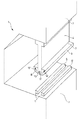
図1には管成形プレス機1が図示されている。管成形プレス機1は、プレス機下部部分2とプレス機上部部分3とから構成されている。管成形プレス機1のプレス機上部部分3には曲げボード4が有利には取り外し可能に固定されている。図示していない駆動部によりプレス機上部部分3を昇降させることにより、対応的に曲げボード4の鉛直方向の運動が行なわれる。
【0015】
プレス機下部部分2には下部成形工具5(ここでは2つの成形リブ6,6’から成る)が配置され、他方曲げボード4は上部成形工具8を備えている。上部成形工具8は、連続成形方式による管製造の場合、曲げボード4の足部7に交換可能に固定される。上部成形工具8は、その下面9において、成形対象である管の内径に整合した半径を有している。
【0016】
上部成形工具8は、曲げボード4の足部7にしっかりと固定されているのではなく、図2の第1実施形態に図示したように、1個の回転枢着部または直列に配置された複数個の回転枢着部10を介して可動に支持されている。回転枢着部10は、上部成形工具8を矢印12または12’の方向で水平縦軸線11のまわりに回転させるのを可能にする。回転枢着部10の回転軸線13は、曲げモーメントを避けるため、管に成形される金属板15の上面14付近にある。すなわち回転軸線13は、成形過程時において曲げボード4に曲げモーメントが作用しないように、曲げボード4の足部7に位置決めされている。正確な姿勢は面圧、軸受サイズ等の考慮すべき諸観点に依存している。上部成形工具8は、非荷重状態では、曲げボード4の両側に取り付けられている弾性要素16,16’により鉛直方向のニュートラルポジションへもたらされる。
【0017】
図3は他の実施形態である。この実施形態では、上部成形工具8の枢着部が拡大されており、すなわち曲げボード4はヘッド端部17において他の回転枢着部18によりプレス機上部部分3と結合されており、その結果曲げボード4の上下において回動運動が伴う一種の二重枢着構成が達成されている。両側に取り付けられた上部弾性要素19,19’により、この固定態様においても、曲げボード4は非荷重状態において鉛直方向のニュートラルポジションへ指向する。
【図面の簡単な説明】
【図1】管成形プレス機(C型プレス機として実施されている)の概略斜視図である。
【図2】第1実施形態による曲げボードの側面図である。
【図3】第2実施形態による曲げボードの側面図である。
【符号の説明】
1 管成形プレス機
2 プレス機下部部分
3 プレス機上部部分
4 曲げボード
5 下部成形工具
6,6’ 成形リブ
7 足部
8 上部成形工具
9 上部成形工具の下面
10 回転枢着部
11 上部成形工具の水平縦軸線
12,12’ 上部成形工具の回転方向
13 回転軸線
14 金属板の表面
15 金属板
16 下部弾性要素
17 ヘッド端部
18 回転枢着部
19,19’ 上部弾性要素[0001]
BACKGROUND OF THE INVENTION
The present invention is an apparatus for manufacturing a tube from a metal plate (for example, a thin steel plate) bent asymmetrically in advance , having a tube forming press machine, and the tube forming press machine is fixed to an upper portion of the press machine. Biegeschwert and press machine lower part with lower forming tool, the upper forming tool is placed on the foot of the bending board, and the upper forming tool of the bending board is bent asymmetrically in advance It is related with the apparatus for manufacturing a pipe | tube from the said metal plate which carried out the eccentric process and carried out the formation process .
[0002]
[Prior art]
As a method for manufacturing a tube from a metal plate, a UOE method, a three-roll bending method, a spiral method, and a tube forming press method are known. In the case of the tube forming press method, a distinction is made between the continuous folding method and the continuous forming method.
[0003]
In order to produce a tube or a large tube according to the continuous forming method, a plurality of successive work steps are required. In the first step, the longitudinal edges of the metal plate are pre-bent. This pre-bending step is usually performed on a separate edge bending press. Pre-bending the vertical edge is the reason that when the slit tube is formed , the tube radius is uniformly formed at the subsequent seam portion (where the vertical edges of the metal plates that are bent into the tube collide with each other). It is to make it. At this point, the metal sheet bent in advance is sent to a tube forming press machine to perform the original bending process. The tube forming press consists of a movable upper part and a lower part. A bending board arranged vertically is coupled to an upper portion of the tube forming press, and an upper forming tool is fixed to a foot portion of the bending board.
[0004]
In a simple embodiment, the lower forming tool consists of two ribs arranged longitudinally at variable intervals. These ribs form a lower cradle for the metal plate to be formed.
[0005]
The metal plate whose longitudinal side is bent in advance is inserted into a tube forming press in a subsequent step, and then a bending force is applied to the metal plate by pushing down the upper portion of the press. In this case, the metal plate is formed by the action of the bending board and the upper forming tool carried thereby. This process is repeated many times until the metal plate is formed into a slit tube.
[0006]
Therefore, the time for forming the slit tube depends on the number of strokes of the tube forming press, and the number of strokes depends on the range formed in one stroke. This forming range is set by the width of the forming tool.
[0007]
The width of the forming tool attached to the foot of the bending board corresponds to several times the cross section of the bending board, and the forming radius depends on the inner diameter of the tube to be produced. Since the metal plate is pre-shaped asymmetrically, this male, rounded forming tool is placed asymmetrically on the metal plate when moving in the vertical direction. This creates a bending moment on the bending board. In order to prevent the bending board from buckling under such an asymmetric load, the bending board has a transverse section taking this bending moment into consideration.
[0008]
[Problems to be solved by the invention]
The object of the present invention is to configure the device in such a manner as to be able to bend a wide range of the metal plate to be formed without increasing the load on the bending board.
[0009]
[Means for Solving the Problems]
In order to solve the above problems, the present invention is such that the upper forming tool is movably supported and can be rotated about its own horizontal longitudinal axis when placed on a metal plate bent asymmetrically in advance. It is a feature.
[0010]
In accordance with the present invention, by supporting bending pivot the upper forming tool to the foot of the board, when the upper forming tool is placed on the metal plate, the upper forming tool is rotatable around its own horizontal longitudinal axis I can .
[0011]
When the bending board is moved up and down in the direction of the lower forming tool on which the metal plate is placed, the first contact between the radius of the forming tool and the metal plate is caused by the upper forming tool fixed to the foot. This is done on the side opposite to the pre-bent side of the metal plate. Since the upper forming tool is pivotally supported on the horizontal longitudinal axis, it rolls on the surface of the metal plate, so that the upper forming tool is wide until the metal plate is placed on both ribs of the lower forming tool, for example. Touch the molding range. From this point, the metal plate starts to be formed through the radius of the upper forming tool.
[0012]
According to another embodiment, the bending board is further pivotally connected to the upper part of the press. With this measure of providing two rotating pivots , the bending board does not generate moments during bending other than a very small moment caused by friction at the rotating pivots .
[0013]
The relative friction value between the upper forming tool and the bending board or between the bending board and the upper part of the press can be controlled by selecting a lubricant and a sliding pair.
[0014]
DETAILED DESCRIPTION OF THE INVENTION
Next, embodiments of the present invention will be described in detail with reference to the accompanying drawings.
FIG. 1 shows a tube forming press 1. The tube forming press 1 includes a press machine lower part 2 and a press machine upper part 3. A bending board 4 is advantageously detachably fixed to the upper part 3 of the press of the tube forming press 1. The vertical movement of the bending board 4 is correspondingly performed by raising and lowering the upper part 3 of the press machine by a drive unit (not shown).
[0015]
A lower forming tool 5 (here consisting of two forming ribs 6, 6 ′) is arranged in the lower part 2 of the press, while the bending board 4 is provided with an upper forming
[0016]
The upper forming
[0017]
FIG. 3 shows another embodiment. In this embodiment, the pivoting part of the upper forming
[Brief description of the drawings]
FIG. 1 is a schematic perspective view of a tube forming press (implemented as a C-type press).
FIG. 2 is a side view of the bending board according to the first embodiment.
FIG. 3 is a side view of a bending board according to a second embodiment.
[Explanation of symbols]
DESCRIPTION OF SYMBOLS 1 Pipe forming press machine 2 Lower part of press machine 3 Upper part of press machine 4
Claims (6)
上部成形工具(8)が可動に支持され、予め非対称に曲げられた金属板(15)の上に載置した場合に自らの水平縦軸線(11)のまわりに回転可能であることを特徴とする装置。An apparatus for manufacturing a pipe from a metal plate (15) bent asymmetrically in advance, comprising a pipe forming press machine (1), the pipe forming press machine (1) being an upper part of the press machine (3) A bending board (4) fixed to the lower part (2) and a lower part (2) of the press machine having a lower forming tool (5). The upper forming tool (8) is attached to the foot (7) of the bending board (4). A tube is formed from the metal plate, wherein the upper forming tool (8) of the bending board (4) is eccentrically placed on the metal plate (15) bent asymmetrically in advance to perform the forming process. In an apparatus for manufacturing,
The upper forming tool (8) is movably supported and is rotatable about its own horizontal longitudinal axis (11) when placed on a metal plate (15) bent asymmetrically in advance. Device to do.
Applications Claiming Priority (1)
| Application Number | Priority Date | Filing Date | Title |
|---|---|---|---|
| DE10232098A DE10232098B4 (en) | 2002-07-15 | 2002-07-15 | Device for producing pipes from sheet metal |
Publications (2)
| Publication Number | Publication Date |
|---|---|
| JP2004082219A JP2004082219A (en) | 2004-03-18 |
| JP4002865B2 true JP4002865B2 (en) | 2007-11-07 |
Family
ID=29761985
Family Applications (1)
| Application Number | Title | Priority Date | Filing Date |
|---|---|---|---|
| JP2003194865A Expired - Lifetime JP4002865B2 (en) | 2002-07-15 | 2003-07-10 | Equipment for manufacturing tubes from metal plates |
Country Status (5)
| Country | Link |
|---|---|
| US (1) | US7004005B2 (en) |
| EP (1) | EP1382402B1 (en) |
| JP (1) | JP4002865B2 (en) |
| AT (1) | ATE340039T1 (en) |
| DE (2) | DE10232098B4 (en) |
Families Citing this family (21)
| Publication number | Priority date | Publication date | Assignee | Title |
|---|---|---|---|---|
| DE202007007517U1 (en) * | 2007-02-16 | 2007-08-09 | Siempelkamp Maschinen- Und Anlagenbau Gmbh & Co. Kg | Press e.g. hydraulic bending press, for use during production of longitudinal seam-welded pipe, has tool carriers arranged on both sides of central support rack of tables so that forces are initiated by opposite sides of support rack |
| WO2009023973A1 (en) * | 2007-08-21 | 2009-02-26 | Soutec Soudronic Ag | Apparatus and process for shaping a tube from a metal sheet |
| DE202008000121U1 (en) * | 2008-01-03 | 2008-04-17 | Eisenbau Krämer mbH | Bending machine |
| JP5393358B2 (en) * | 2009-09-08 | 2014-01-22 | 住友重機械工業株式会社 | Plate bending press |
| DE102011009660B4 (en) | 2011-01-27 | 2013-05-29 | Sms Meer Gmbh | Apparatus and method for forming flat products in slotted tubes or pipe precursors |
| DE102011007396A1 (en) | 2011-04-14 | 2012-10-18 | Ing. Erich Pfeiffer Gmbh | Discharge head for a tube and tube with discharge head |
| DE102011053676B4 (en) | 2011-09-16 | 2016-09-08 | EISENBAU KRäMER GMBH | Tube bending machine |
| CA2880661C (en) * | 2012-08-09 | 2018-05-22 | Jfe Steel Corporation | Method of producing steel pipe |
| EP3006133B1 (en) * | 2013-05-24 | 2017-08-16 | JFE Steel Corporation | Method for producing steel pipe |
| EP3006128B1 (en) * | 2013-05-29 | 2018-10-24 | JFE Steel Corporation | Method of manufacturing a welded steel pipe |
| JP6262166B2 (en) | 2014-03-31 | 2018-01-17 | Jfeスチール株式会社 | Bending press mold |
| DE102014116192A1 (en) * | 2014-11-06 | 2016-05-12 | Siempelkamp Maschinen- Und Anlagenbau Gmbh | Pipe bending machine |
| CN106238520A (en) * | 2016-08-31 | 2016-12-21 | 陈富强 | The improvement folded block of welding bender |
| DE102016219706A1 (en) | 2016-10-11 | 2018-04-12 | Sms Group Gmbh | Forming press with bending rate |
| EP3597322A4 (en) | 2017-03-15 | 2021-01-13 | JFE Steel Corporation | Press mold and method for manufacturing steel pipe |
| CN107855382A (en) * | 2017-11-27 | 2018-03-30 | 安徽东海机床制造有限公司 | A kind of Bending Processing method of round piece |
| CN107803412A (en) * | 2017-11-27 | 2018-03-16 | 安徽东海机床制造有限公司 | A kind of frame bender and its application |
| CN108580621A (en) * | 2018-06-04 | 2018-09-28 | 北京京诚之星科技开发有限公司 | A kind of corrugated plating molding starting the arc machine |
| RU2769596C1 (en) | 2018-09-14 | 2022-04-04 | ДжФЕ СТИЛ КОРПОРЕЙШН | Method of making steel pipe and matrix |
| CN112404164A (en) * | 2020-11-10 | 2021-02-26 | 上海宝冶集团有限公司 | Technological method for pressing and forming square tube |
| CN112872130B (en) * | 2021-01-19 | 2023-05-05 | 安徽泓鞍机械制造有限公司 | Industrial steel pipe bending device |
Family Cites Families (14)
| Publication number | Priority date | Publication date | Assignee | Title |
|---|---|---|---|---|
| US1914979A (en) * | 1931-03-21 | 1933-06-20 | Bendix Brake Co | Riveting mechanism |
| US2562565A (en) * | 1947-03-28 | 1951-07-31 | Albert W Merk | Electro-type straightener with rocking plate sections |
| US2763924A (en) * | 1953-12-29 | 1956-09-25 | Bellometti Ugo | Process and apparatus for manufacturing tubes, tanks and hollow bodies generally from metal in sheet or band form |
| DE1183465B (en) * | 1962-02-01 | 1964-12-17 | Siempelkamp Gmbh & Co | Bending tool for the production of cylindrical or conical tubes from flat sheet metal blanks |
| FI45165C (en) * | 1970-07-21 | 1972-04-10 | Fiskars Ab Oy | Cleaning arrangements for forging machines for damping of the machine's under-directed blows. |
| DE2218419C2 (en) * | 1972-04-13 | 1973-10-25 | Mannesmann-Meer Ag, 4050 Moenchengladbach | Bending press, especially for a plant for the production of large pipes |
| DE2402190C3 (en) * | 1974-01-17 | 1978-03-02 | Mitsubishi Jukogyo K.K., Tokio | Device for bending steel sheets or plates |
| JPS5841621A (en) * | 1981-09-07 | 1983-03-10 | Mitsubishi Heavy Ind Ltd | Attitude holding method of punch head |
| JPS59199116A (en) * | 1983-04-28 | 1984-11-12 | Nippon Kokan Kk <Nkk> | Punching device of u-press used for manufacture of uoe-pipe |
| JPS59209425A (en) * | 1983-05-12 | 1984-11-28 | Nippon Kokan Kk <Nkk> | U press tool for uoe steel tube manufacturing process |
| JPS62142026A (en) * | 1985-12-16 | 1987-06-25 | Kawasaki Steel Corp | Tubular body forming machine |
| NL8600462A (en) * | 1986-02-25 | 1987-09-16 | Philips Nv | DEVICE FOR COMPRESSING A STACK ABOVE LAYERS. |
| DE4138285C2 (en) * | 1991-11-21 | 1994-04-07 | M & S Brugg Ag Brugg | Hydraulic press brake |
| JP2001252722A (en) * | 2000-03-09 | 2001-09-18 | Sumitomo Metal Ind Ltd | U press tool and manufacturing method of uoe steel tube |
-
2002
- 2002-07-15 DE DE10232098A patent/DE10232098B4/en not_active Expired - Fee Related
-
2003
- 2003-07-05 DE DE50305093T patent/DE50305093D1/en not_active Expired - Lifetime
- 2003-07-05 EP EP03015232A patent/EP1382402B1/en not_active Expired - Lifetime
- 2003-07-05 AT AT03015232T patent/ATE340039T1/en not_active IP Right Cessation
- 2003-07-10 JP JP2003194865A patent/JP4002865B2/en not_active Expired - Lifetime
- 2003-07-11 US US10/617,577 patent/US7004005B2/en not_active Expired - Lifetime
Also Published As
| Publication number | Publication date |
|---|---|
| EP1382402B1 (en) | 2006-09-20 |
| ATE340039T1 (en) | 2006-10-15 |
| EP1382402A2 (en) | 2004-01-21 |
| DE10232098B4 (en) | 2004-05-06 |
| DE10232098A1 (en) | 2004-02-05 |
| US20040055356A1 (en) | 2004-03-25 |
| JP2004082219A (en) | 2004-03-18 |
| EP1382402A3 (en) | 2005-03-09 |
| US7004005B2 (en) | 2006-02-28 |
| DE50305093D1 (en) | 2006-11-02 |
Similar Documents
| Publication | Publication Date | Title |
|---|---|---|
| JP4002865B2 (en) | Equipment for manufacturing tubes from metal plates | |
| JP6188282B2 (en) | Method and apparatus for manufacturing slit tube from plate material | |
| JPS6356010B2 (en) | ||
| US9192972B2 (en) | Forming method and forming device | |
| JPH034242B2 (en) | ||
| JP6512665B2 (en) | Roller hemming device, and roller hemming method | |
| KR20040044977A (en) | A method of bending metal roofing sheets and a bending apparatus | |
| CN211247832U (en) | Five metals stamping workpiece bending device | |
| JP2008516771A (en) | Method and edge-bending press apparatus for edge-bending a thin strip strip formed into a grooved tube | |
| CN108213129A (en) | A kind of U-shaped bending equipment | |
| KR101263709B1 (en) | Manufacturing apparatus for wire mesh filter | |
| JP2018187649A (en) | Square steel tube manufacturing equipment and manufacturing method of square steel tube | |
| US3535905A (en) | Rectilinear edge flanging tool for sheet metal workpieces | |
| JP3642020B2 (en) | Roll hemming method | |
| CN210701838U (en) | Metal tube forming machine | |
| CN210435101U (en) | Bending device of tubular product | |
| CN209006455U (en) | A kind of spiral welded pipe steel plate pre-bending device | |
| JP3589257B2 (en) | Form bending method and bending apparatus | |
| JP7462487B2 (en) | Metal bending method and device | |
| JP3399312B2 (en) | Method and apparatus for bending edge of steel plate at the time of forming welded pipe | |
| JPH0261334B2 (en) | ||
| US7004001B2 (en) | Roll forming apparatus for forming sheet material into multiple shapes | |
| EP3243577A2 (en) | A forming unit for a profiling machine line | |
| JPH0333414B2 (en) | ||
| CN217798197U (en) | Straightening device for air conditioner copper pipe production |
Legal Events
| Date | Code | Title | Description |
|---|---|---|---|
| A621 | Written request for application examination |
Free format text: JAPANESE INTERMEDIATE CODE: A621 Effective date: 20040421 |
|
| A131 | Notification of reasons for refusal |
Free format text: JAPANESE INTERMEDIATE CODE: A131 Effective date: 20051220 |
|
| A601 | Written request for extension of time |
Free format text: JAPANESE INTERMEDIATE CODE: A601 Effective date: 20060320 |
|
| A602 | Written permission of extension of time |
Free format text: JAPANESE INTERMEDIATE CODE: A602 Effective date: 20060324 |
|
| A521 | Request for written amendment filed |
Free format text: JAPANESE INTERMEDIATE CODE: A523 Effective date: 20060613 |
|
| A131 | Notification of reasons for refusal |
Free format text: JAPANESE INTERMEDIATE CODE: A131 Effective date: 20061121 |
|
| A601 | Written request for extension of time |
Free format text: JAPANESE INTERMEDIATE CODE: A601 Effective date: 20070220 |
|
| A602 | Written permission of extension of time |
Free format text: JAPANESE INTERMEDIATE CODE: A602 Effective date: 20070226 |
|
| A521 | Request for written amendment filed |
Free format text: JAPANESE INTERMEDIATE CODE: A523 Effective date: 20070521 |
|
| TRDD | Decision of grant or rejection written | ||
| A01 | Written decision to grant a patent or to grant a registration (utility model) |
Free format text: JAPANESE INTERMEDIATE CODE: A01 Effective date: 20070814 |
|
| A61 | First payment of annual fees (during grant procedure) |
Free format text: JAPANESE INTERMEDIATE CODE: A61 Effective date: 20070820 |
|
| FPAY | Renewal fee payment (event date is renewal date of database) |
Free format text: PAYMENT UNTIL: 20100824 Year of fee payment: 3 |
|
| R150 | Certificate of patent or registration of utility model |
Ref document number: 4002865 Country of ref document: JP Free format text: JAPANESE INTERMEDIATE CODE: R150 Free format text: JAPANESE INTERMEDIATE CODE: R150 |
|
| FPAY | Renewal fee payment (event date is renewal date of database) |
Free format text: PAYMENT UNTIL: 20110824 Year of fee payment: 4 |
|
| R250 | Receipt of annual fees |
Free format text: JAPANESE INTERMEDIATE CODE: R250 |
|
| FPAY | Renewal fee payment (event date is renewal date of database) |
Free format text: PAYMENT UNTIL: 20120824 Year of fee payment: 5 |
|
| R250 | Receipt of annual fees |
Free format text: JAPANESE INTERMEDIATE CODE: R250 |
|
| FPAY | Renewal fee payment (event date is renewal date of database) |
Free format text: PAYMENT UNTIL: 20130824 Year of fee payment: 6 |
|
| R250 | Receipt of annual fees |
Free format text: JAPANESE INTERMEDIATE CODE: R250 |
|
| R250 | Receipt of annual fees |
Free format text: JAPANESE INTERMEDIATE CODE: R250 |
|
| R250 | Receipt of annual fees |
Free format text: JAPANESE INTERMEDIATE CODE: R250 |
|
| R250 | Receipt of annual fees |
Free format text: JAPANESE INTERMEDIATE CODE: R250 |
|
| R250 | Receipt of annual fees |
Free format text: JAPANESE INTERMEDIATE CODE: R250 |
|
| R250 | Receipt of annual fees |
Free format text: JAPANESE INTERMEDIATE CODE: R250 |
|
| R250 | Receipt of annual fees |
Free format text: JAPANESE INTERMEDIATE CODE: R250 |
|
| R250 | Receipt of annual fees |
Free format text: JAPANESE INTERMEDIATE CODE: R250 |
|
| R250 | Receipt of annual fees |
Free format text: JAPANESE INTERMEDIATE CODE: R250 |
|
| R250 | Receipt of annual fees |
Free format text: JAPANESE INTERMEDIATE CODE: R250 |
|
| R250 | Receipt of annual fees |
Free format text: JAPANESE INTERMEDIATE CODE: R250 |
|
| EXPY | Cancellation because of completion of term |