JP3978743B2 - Traverse tray hawk mounting structure - Google Patents
Traverse tray hawk mounting structure Download PDFInfo
- Publication number
- JP3978743B2 JP3978743B2 JP2002149850A JP2002149850A JP3978743B2 JP 3978743 B2 JP3978743 B2 JP 3978743B2 JP 2002149850 A JP2002149850 A JP 2002149850A JP 2002149850 A JP2002149850 A JP 2002149850A JP 3978743 B2 JP3978743 B2 JP 3978743B2
- Authority
- JP
- Japan
- Prior art keywords
- tray
- hawk
- support frame
- engagement portion
- fork
- Prior art date
- Legal status (The legal status is an assumption and is not a legal conclusion. Google has not performed a legal analysis and makes no representation as to the accuracy of the status listed.)
- Expired - Fee Related
Links
Images


Description
【0001】
【発明の属する技術分野】
本発明は、駐車室に配置した横行トレイに搭載する車両のタイヤを受ける櫛歯形状のトレイホークの取付け構造に関するものである。
【0002】
【従来の技術】
従来のホーク式の駐車塔50は、昇降空間Eに昇降リフト3を配置して、昇降空間Eに隣接して駐車室X・Yを複数階に亘って設け、駐車室X・Yには横行トレイ51を配置し、横行トレイ51を横行させる横行駆動部8が各階駐車室X・Yと昇降空間Eに面一で水平に設けられている。横行トレイ51は、前後端を断面コ字状のトレイレール16を備え、トレイレール16を支持する横行駆動部8により横行可能にしている。横行駆動部8は、複数の駆動ローラ9を軸着したローラ体であり、ローラフレームにより支持され、駆動ローラ9の駆動回転により横行トレイ51を駐車室X・Yと昇降空間Eとを往復動させている。
【0003】
駆動ローラ9は、水平で一線上に軸着して、横行駆動モータの駆動回転により回転可能にして、複数個を軸着したローラ体とし、各階の駐車室X・Yと、駐車室X・Yに隣接した昇降空間Eとの前後端に一線状に配置し、横行トレイ51のトレイレール16を駆動ローラ9が支持して水平方向に横行移動させる。
横行トレイ51を横行させる駐車室X・Yの横行駆動部8と昇降空間Eの横行駆動部8とは、各階の駐車室X・Yと駐車室X・Yに隣接した昇降空間Eとに、複数階に亘って形成され、横行駆動部8に取付けされた横行駆動モータによって、駆動ローラ9を移動方向に回転させ、横行トレイ51を横行させている。
【0004】
昇降リフト3は、昇降空間Eの4隅に立設したガイドレール6に案内される昇降リフト3が左右一対に前後方向に備えられ、櫛歯形状にリフトホーク4が固定され、互いに内側に向けて突出させている。リフトホーク4は、車両CのタイヤTを搭載して乗込場Sから各階の駐車室X・Yの昇降空間Eに搬送して、横行トレイ51のトレイホーク52とすれ違って移載することで、入出庫させることができる。
【0005】
横行トレイ51は、前後端にトレイレール16を備え、横行駆動部8の駆動ローラ9に支持され、中央に前後のトレイレール16を連結する支持フレーム15が長手方向に備えられ、その支持フレーム15の側面からトレイホーク52を櫛歯形状に左右方向の外側に突出させている。
支持フレーム15に固定されたトレイホーク52は、角パイプ材・半丸材・Tバー材等が採用され支持フレーム15の側面に、リフトホーク4がすれ違う間隔を空けて溶接で櫛歯形状にしている。
【0006】
駐車塔50の高さは、ほとんどが複数階に積重ねた駐車室X・Yにより形成され、横行トレイ51のトレイホーク52上面と支持フレーム15の下面との距離のホーク高L1が無駄な高さになっている。昇降リフト3のリフトホーク4と横行トレイ51のトレイホーク5は、各ホーク間をすれ違い可能に配置してあり、横行トレイ51が駐車室X・Yから昇降空間Eに横行して、昇降リフト3と横行トレイ51がすれ違って車両Cを受け渡しして、乗込場Sから駐車室X・Yに入庫、又は駐車室X・Yから乗込場Sに出庫可能にしている。
【0007】
【発明が解決しようとする課題】
しかし、従来のホーク式の駐車塔では、横行トレイのトレイホーク上面位置とトレイホークを固定する支持フレームの下面とにホーク高がある。ホーク高は、支持フレームにトレイホークを溶接固定して、車両の荷重を支えるために必要とする位置である。ホーク高の距離は、駐車室の高さを高くすることになり、各階の駐車室の高さは階高といい、駐車室を複数階に亘り積重ねて形成するため、駐車塔の高さに大きく影響することになる。
【0008】
駐車塔の高さは規定の高さがあり、その高さを超えると建築基準法により設計及び建築費用が大きく増大することによりコストアップになる。規定の高さ以内に建築するには、駐車塔の階数を減らすことで解決していたが、階数を減らすと駐車容量が少なくなり、駐車台数当たりのコストが大きく上がり高い製品になり、他製品に比べコスト競争力が無くなる問題があった。
【0009】
本発明は、規定の高さ以内により多くの駐車室を配置して、建築コストをさげることで、駐車台数当たりのコストをさげることを目的にした横行トレイのホーク取付け構造である。
本目的を達成するには、駐車室の高さをより低くすることにあり、低くするために横行トレイのトレイホークの固定位置をフレームの下面に近づけ、ホーク高を少なくすることにより、階高を低くすることができ、それにより駐車室を増加させることで安価な駐車塔を提供することにある。
【0010】
【課題を解決するための手段】
請求項1の発明では、車両を搭載する横行トレイは、長手方向に配置して荷重を支持する支持フレームを備え、前記支持フレームの前後端に移動手段を配置して、支持フレームにトレイホークを下方向に係止させる第一係合部を設ける。トレイホークは、横行トレイに搭載する車両のタイヤを支持可能にして、そのトレイホークに第一係合部と当接する第二係合部を設ける。支持フレームの側面には、トレイホークを貫通させる断面形状の透孔を配置した第一係合部を設ける。トレイホークには、第二係合部を設ける。第一係合部と第二係合部は、当接可能にして、互いに逆テーパを有する断面形状に設ける。横行トレイのホークの取付けは、前記透孔にトレイホークを嵌合して形成する構成とする。
【0011】
請求項2の発明では、車両を搭載する横行トレイは、長手方向に配置して荷重を支持する支持フレームを備え、前記支持フレームの前後端に移動手段を配置して、支持フレームにトレイホークを下方向に係止させる第一係合部を設ける。トレイホークは、横行トレイに搭載する車両のタイヤを支持可能にして、そのトレイホークに第一係合部と当接する第二係合部を設ける。当接部は、第一係合部を支持フレームの上面に設け、第二係合部を第一係合部に搭載して、支持フレームに上面から支持フレームの下面に向けて冠状に嵌合させる構成にする。
【0012】
請求項3の発明では、複数本のトレイホークを一体に固定し、櫛歯状のホーク体を形成して、支持フレームの第一係合部にホーク体の第二係合部を嵌合する構成にする。
請求項4の発明では、車両のタイヤを搭載する左右一対のトレイホークを形成した第二係合部を支持フレームの第一係合部に嵌合させる構成とする。
【0013】
次に、上述した請求項以外の技術思想を作用効果共に記載すると、トレイホークは支持フレームの側面から先端方向に向けて断面高をテーパ状に低くして行く構成にする。この構成により、トレイホークが支持フレームの下面に近づけることができ車幅の広い車両ほど階高の高い駐車室になる効果がある。
【0014】
請求項1の構成では、トレイホークを支持フレームの下面に近づけて固定力を強化して脱落防止の作用がある。
請求項2の構成では、フレームの上部に掛け渡してあるために、一段と剛性を強化できる作用がある。
請求項3の構成では、別途にトレイホークを櫛状に形成できるため、組付け作業が早くできる作用がある。
請求項4の構成では、トレイホークを支持フレームの一部としてフレームを強化する作用がある。
【0015】
【発明の実施の形態】
本発明の駐車塔1の駐車室X・Yに配置した横行トレイ2について、具体化した一実施形態を図1〜図7に示し説明する。図1は、地上面GLに立設したホーク式の駐車塔1であり、昇降空間Eの地上面GL位置に乗込場Sを備え、乗込場Sに内蔵されたターン装置が設置してあり車両Cを方向転換することができ、各階の昇降空間Eに隣接させて駐車室X・Yを備えている。駐車室X・Yは、横行トレイ2を備え車両Cを搭載可能にして、横行駆動部8で横行可能にし、昇降空間Eへ往復できるようにしてある。
【0016】
横行駆動部8は、複数個の駆動ローラ9を水平に軸着して、駐車室X・Yと昇降空間Eとの前後端に配置され、駆動ローラ9が横行トレイ2のトレイレール16を支持して昇降空間Eに横行可能に配置している。昇降リフト3は、昇降空間Eを昇降可能に上部の昇降駆動部7から索状体10を介して吊下げられ、昇降空間Eの4隅に立設したガイドレール6に案内されて横行トレイ2とすれ違い可能にしてある。
【0017】
車両Cの乗込場Sは、駐車塔1の地上面GL上にあり、昇降リフト3が位置しているとき乗入れることができ、人の通行もできる平面状の床面にしてある。
昇降リフト3には、複数のリフトホーク4が櫛状に固定してあり、車両CのタイヤTを搭載して昇降駆動部7で昇降させて搬送する。
【0018】
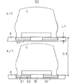
図2は、横行トレイ2の支持フレーム15の第一係合部17に、トレイホーク5の第二係合部18を嵌合させて固定した。横行トレイ2のホーク取付け構造を示している。図2(a)では、断面半円状のトレイホーク5aにして、支持フレーム15にはトレイホーク5aの断面径の透孔11を下面に近づけるために下方を切り捨てて、トレイホーク5aを受け止める第一係合部17の形状にし、断面半円状の第二係合部18として嵌合させて固定してある。図2(b)では、逆テーパの断面台形状にした支持フレーム15の透孔11を第一係合部17と、トレイホーク5bの断面台形状の第二係合部18とによる嵌合で固定する。
【0019】
図2(c)の支持フレーム15の上面には、トレイホーク5cの形状をした第一係合部17として設け、トレイホーク5cを左右のタイヤTを受けるように一対にした一体のものにして、タイヤT位置を下方に来るように曲げて支持フレーム15の下面に近づけている。
【0020】
図3(a)は、支持フレーム15を不等辺鋼にして、トレイホーク5dをコ字形状に成形したもので、支持フレーム15とトレイホーク5dとの嵌合部に別途取付けた逆テーパを有する係合部材12を双方に備えている。係合部材12は、支持フレーム15にトレイホークを下方向に係止させる第一係合部17を備えて、トレイホーク5dに第一係合部と当接する第二係合部18を備え、支持フレームの下面の近傍にトレイホークを位置させる状態を示している。
【0021】
図3(b)は、トレイホーク5を櫛状に一体に形成したものを一体部材13として、逆テーパを備えた第二係合部18を設け、支持フレーム15の側面に第二係合部18のテーパ面を第一係合部17として嵌合させ、ボルト等により螺合することにより横行トレイ2の櫛歯を形成でき、現地工事組付けを容易にすることができるため、分割して搬送すれば重積することができるために運送費を安価にすることができる。
【0022】
図4(a)は、不等辺材の支持フレーム15を2本備え、上面を第一係合部17として、一体部材13にトレイホーク5eを複数本櫛状に形成して第二係合部18として、左右一対のホーク部を支持フレーム15に嵌合させる。2本の支持フレーム15は、左右一対の一体部材13を連結材14で接続されることで、分離した2本の支持フレーム15を一体化し剛性を高めることになる。図4(a)では、連結材14を1本で接続しているが、複数本にしてもよい。トレイホーク5eは、タイヤTを支持フレーム15に近づけている。
【0023】
図4(b)は、横行トレイ2の一部を示すものであり、2本の支持フレーム15にトレイホーク5cを冠状に載置して、支持フレーム15の内側を第一係合部17に、第二係合部18の係合部材12で固定し、支持フレーム15を連結材14で接続して一体にすることで剛性を高めている。
図4(c)は、2本の支持フレーム15の内側からトレイホーク5a・5bの第二係合部18の係合部材12により第一係合部17に固定され、部分的に貫通させて支持フレーム15の剛性を高めている。
【0024】
図5(a)は、2本の支持フレーム15の第一係合部17に上方から連結材14で1本化したトレイホーク5eの第二係合部18を嵌合させることで剛性を高め、タイヤT位置を低くさせている。
図5(b)は、支持フレーム15に第一係合部17とトレイホーク5eに第二係合部18を備え嵌合している。第一係合部17は、支持フレーム15の上面の一部に逆テーパの透孔11を備え、トレイホーク5eには前記透孔11に係合する係合部材12が備えられている。
【0025】
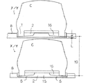
図6は、各階の駐車室X・Yを示し、駐車室X・Yに配置した横行トレイ2に車両Cを搭載している。駐車室X・Yの高さは、階高19として表示され、その階高に入庫される車両Cの高さは階高19より低い車高まで許容高さにある。
車両CのタイヤT底位置とフレーム15下面位置の距離であるホーク高Lがある。駐車塔1の駐車台数は、多いほど台当たり金額が安価なものとなるため、階高19を低くして、ホーク高Lも薄くすることで増加することができる。
【0026】
図7は、横行トレイ2の駆動手段を前後端の異なる2種類を採用することで、他端の横行駆動部8を無くし、駐車室X・Yを広くすることができるので、階高19をより低くすることができる。トレイレール16の一端は、コ字か逆L字形状にして、横行駆動部8を複数個の駆動ローラ9で支持し横行させる。トレイレール16の他端は、横行駆動部8の位置に平面の板状のレールを配置して、回転自在に軸着した車輪20を両端に2輪を対にして設けられ、駆動部を持たないシンプルなものにしている。横行トレイ2の横行は、駆動ローラ9の回転力が支持フレーム15の連結により、他端の車輪20が従動されて移動する。トレイホーク5eは、支持フレーム15の左右方向に接続してあり、剛性を高めている。
【0027】
(入庫処理の説明)
駐車塔1に車両Cを入庫する動作について説明する。車両Cは、地上面GLから乗込場Sに乗入れて図示略の操作盤で駐車室X・Yを指定する。
昇降リフト3は、乗込場Sの床面に待機状態でいたが、操作盤の指令により上昇を始めて、車両CのタイヤTをリフトホーク4が受け、指定階より若干上方位置まで上昇して停止する。
【0028】
横行トレイ2は、駐車室X・Yから昇降空間Eに横行して昇降リフト3の下段に位置すると、昇降リフト3が下降してリフトホーク4とトレイホーク5とすれ違うことで、車両Cを横行トレイ2に移載することになる。昇降リフト3は、下降を続け乗込場Sまで行き床面と一体になり、平坦な通路を形成し次の動作の待機状態になる。
【0029】
前記車両Cを搭載した横行トレイ2は、支持フレーム15と連結材14が剛性を高めた構造体になり、車重に耐えて略水平状態を保持して、もとの駐車室X・Yに移動して入庫を完了する。駐車室X・Yには、横行トレイ2の下面にわずかな間隙を付けて、下段の横行トレイ2に搭載された車両Cの屋根があり、階高19を低いものにしている。
【0030】
(出庫動作の説明)
つぎに、出庫の動作について説明する。出庫車両Cは、操作盤で指令すると、指定された駐車室X・Yから横行トレイ2が、横行駆動部8の駆動ローラ9の回転で昇降空間Eに移動して、昇降空間Eを閉じる状態にする。昇降リフト3は、指定された階の駐車室X・Yより上方まで上昇して、横行トレイ2とすれ違い、車両Cを受け取る。横行トレイ2は、搭載していた車両Cを昇降リフト3に移載すると、空車になりスムースに駐車室X・Yに収納され、昇降空間Eを開口状態にする。昇降リフト3は、車両Cを搭載して下降を始め、乗込場Sで床面と一体の通路を形成する。車両Cは、乗込場Sから乗り出して出庫を完了する。
【0031】
本発明の実施形態については、地上面GL上に設置された駐車塔1で説明しているが、地下にも駐車室X・Yを備えたものでも、本発明の横行トレイ2を採用することができる。更に、駐車塔1に車両Cを直接乗込むのではなく、別途位置に設けた乗込み位置から図示無しの搬送台車で駐車塔1の乗込場Sに乗入れる構成の横行トレイ2に採用してもよい。
【0032】
【発明の効果】
請求項1の発明では、横行トレイに搭載する車両のタイヤが、フレームの下面近くにできるので、フレームの高さだけ車室高を効率よく利用できるため、階高を低く設定することができ、一定高さの駐車塔に車室を増設することも、駐車塔の高さを低くすることもできる。
更に、トレイホークは、係合部で固定できるため軽量にして剛性の高いものにして、製作が容易にでき、断面を逆テーパの透孔により、剛性の高い安価な横行トレイにすることができ、トレイホークをより支持フレームの下面に近づけることができる効果がある。
請求項2の発明では、トレイホークの固定を簡単に確実に固定することができ、安価に横行トレイを製作することができる。
請求項3の発明では、トレイホークを一体に組付けることができるので、現地で簡単に強固に固定することができ少ない工数でよく、現地への搬送に櫛歯部分を別途にすることでより多く運ぶことができる効果がある。
請求項4の発明では、横行トレイのフレームに連結することで、フレームの剛性を高めることができ、軽量な横行トレイを形成することができる。
【図面の簡単な説明】
【図1】地上面に立設した駐車塔の正面断面図。
【図2】(a)横行トレイの支持フレームに円型の第一係合部を備えた透孔と、透孔に嵌合させる半円断面形状のトレイホークの第二係合部を示す斜視図。
(b)逆テーパ状の透孔を備えた第一係合部と、同一断面形状の第二係合部を示す斜視図。
(c)支持フレームに搭載して係合させるトレイホークを示す斜視図。
【図3】(a)支持フレームに設けた第一係合部と、トレイホークに設けた第二係合部の構成を説明する斜視図。
(b)同実施形態の別例を示す斜視図。
【図4】(a)一体に形成したトレイホークを嵌合させた斜視図。
(b)左右一対のトレイホーク示す斜視図。
(c)トレイホークに第二係合部材を設けた斜視図。
【図5】(a)先端方向にテーパ状の断面高さにしたトレイホークの斜視図。
(b)同実施形態の別例を示す斜視図。
【図6】駐車室に設置された横行トレイと、横行トレイに搭載した車両との関係を示す駐車室の正面図。
【図7】横行トレイの横行駆動部を示す説明用の斜視図。
【図8】従来の駐車室に配置された横行トレイと、横行トレイに搭載した車両との関係を示す駐車室の正面図。
【符号の説明】
1 駐車塔
2 横行トレイ
3 昇降リフト
4 リフトホーク
5 トレイホーク
11 透孔
12 係合部材
13 一体部材
14 連結材
15 支持フレーム
17 第一係合部
18 第二係合部
19 階高
L ホーク高[0001]
BACKGROUND OF THE INVENTION
The present invention relates to a mounting structure for a comb-shaped tray hawk that receives a tire of a vehicle mounted on a transverse tray disposed in a parking room.
[0002]
[Prior art]
A conventional hawk-
[0003]
The
The traversing
[0004]
The
[0005]
The traversing
The
[0006]
The height of the
[0007]
[Problems to be solved by the invention]
However, in a conventional hawk-type parking tower, there is a hawk height between the tray hawk upper surface position of the transverse tray and the lower surface of the support frame that fixes the tray hawk. The hawk height is a position required to support the load of the vehicle by welding and fixing the tray hawk to the support frame. The distance of the hawk height is to increase the height of the parking room, the height of the parking room on each floor is called the floor height, and the parking rooms are stacked and formed over multiple floors. It will have a big impact.
[0008]
The height of the parking tower has a prescribed height, and beyond that height, the design and construction costs are greatly increased by the Building Standards Act, resulting in an increase in cost. In order to build within the specified height, the problem was solved by reducing the number of floors in the parking tower. However, if the number of floors is reduced, the parking capacity will be reduced, and the cost per parking lot will be greatly increased, resulting in higher products. There was a problem that cost competitiveness was lost.
[0009]
The present invention is a traverse tray hawk mounting structure aimed at reducing the cost per parking lot by arranging more parking rooms within a specified height and reducing the construction cost.
In order to achieve this purpose, the height of the parking room is to be lowered, and in order to reduce the height, the fixed position of the tray fork of the traverse tray is brought closer to the lower surface of the frame, and the height of the floor is reduced by reducing the height of the fork. It is to provide an inexpensive parking tower by increasing the number of parking rooms.
[0010]
[Means for Solving the Problems]
In the invention according to
[0011]
In the invention of
[0012]
In the invention of
In a fourth aspect of the invention, the second engagement portion formed with a pair of left and right tray forks on which the vehicle tire is mounted is fitted to the first engagement portion of the support frame.
[0013]
Next, when the technical ideas other than the above-mentioned claims are described together with the function and effect, the tray hawk is configured so that the cross-sectional height decreases in a tapered shape from the side surface of the support frame toward the distal end. With this configuration, the tray hawk can be brought close to the lower surface of the support frame, and a vehicle with a wider vehicle width has an effect of becoming a parking room with a higher floor height.
[0014]
According to the first aspect of the present invention , the tray hawk is brought close to the lower surface of the support frame to enhance the fixing force and to prevent the drop-off.
In the second aspect, because that is spanned to the upper portion of the frame, an effect that can further enhance the rigidity.
In the structure of
In the structure of Claim 4, there exists an effect | action which strengthens a flame | frame by using trayhawk as a part of support frame.
[0015]
DETAILED DESCRIPTION OF THE INVENTION
A specific embodiment of the traversing
[0016]
The
[0017]
The boarding place S of the vehicle C is on the ground surface GL of the
A plurality of lift forks 4 are fixed in a comb shape on the
[0018]
In FIG. 2, the
[0019]
The upper surface of the
[0020]
FIG. 3 (a) shows the
[0021]
In FIG. 3B, a
[0022]
4 (a) is two Bei example the
[0023]
FIG. 4 (b) shows a part of the traversing
FIG. 4 (c) shows that the first engaging
[0024]
In FIG. 5A, the rigidity is increased by fitting the second engaging
In FIG. 5B, the
[0025]
FIG. 6 shows the parking rooms X and Y on each floor, and the vehicle C is mounted on the
There is a hawk height L that is the distance between the bottom position of the tire T of the vehicle C and the lower surface position of the
[0026]
In FIG. 7, by adopting two types of driving means for the traversing
[0027]
(Description of goods receipt processing)
An operation of warehousing the vehicle C in the
The
[0028]
When the traversing
[0029]
The traversing
[0030]
(Explanation of shipping operation)
Next, the operation of shipping will be described. When the unloading vehicle C gives a command on the operation panel, the traversing
[0031]
Although the embodiment of the present invention is described with the
[0032]
【The invention's effect】
In the invention of
Furthermore, since the tray hawk can be fixed at the engaging portion, it can be made lighter and more rigid so that it can be easily manufactured, and the cross section can be made into a low-cost transverse tray with high rigidity by using a reverse-tapered through hole. The tray hawk can be brought closer to the lower surface of the support frame .
In the invention of
In the invention of
In the invention of claim 4, by connecting to the frame of the transverse tray, the rigidity of the frame can be increased, and a lightweight transverse tray can be formed.
[Brief description of the drawings]
FIG. 1 is a front sectional view of a parking tower erected on the ground surface.
FIG. 2A is a perspective view showing a through hole provided with a circular first engaging portion on a support frame of a transverse tray and a second engaging portion of a tray fork having a semicircular cross-sectional shape fitted into the through hole. Figure.
(B) The perspective view which shows the 1st engaging part provided with the reverse-tapered through-hole, and the 2nd engaging part of the same cross-sectional shape.
(C) The perspective view which shows the tray hawk which mounts and supports on a support frame.
FIG. 3A is a perspective view illustrating a configuration of a first engagement portion provided on a support frame and a second engagement portion provided on a tray hawk.
(B) The perspective view which shows another example of the same embodiment.
FIG. 4A is a perspective view in which an integrally formed tray hawk is fitted.
(B) The perspective view which shows a pair of left and right tray hawks.
(C) The perspective view which provided the 2nd engagement member in tray hawk.
FIG. 5A is a perspective view of a tray fork having a cross-sectional height tapered in the tip direction.
(B) The perspective view which shows another example of the same embodiment.
FIG. 6 is a front view of a parking room showing a relationship between a transverse tray installed in the parking room and a vehicle mounted on the transverse tray.
FIG. 7 is an explanatory perspective view showing a transverse drive unit of a transverse tray.
FIG. 8 is a front view of a parking room showing a relationship between a transverse tray disposed in a conventional parking room and a vehicle mounted on the transverse tray.
[Explanation of symbols]
DESCRIPTION OF
Claims (4)
横行トレイは前後方向に荷重を支持する支持フレームを備え、
前記支持フレームの前後端に横行トレイの移動手段を配置し、
前記支持フレームに下方向に係止するように側面にトレイホークを貫通させる断面形状の透孔を配置した第一係合部を設けて、
車両のタイヤを支持するトレイホークに第一係合部と当接する第二係合部材を設け、
前記第一係合部と前記第二係合部は、当接可能にして互いに逆テーパを有する断面形状に設け、前記透孔に前記トレイホークを嵌合して形成することを特徴とする横行トレイのホーク取付け構造。Passing the elevating lift having a lift fork comb shape by elevating the lift space, are arranged in a parking chamber adjacent to the lift space, and rampant tray having a comb-like trays Hawk and enables rampant, by the vehicle In the Hawk-type parking tower that can be configured,
The traverse tray has a support frame that supports the load in the front-rear direction,
A traversing tray moving means is disposed at the front and rear ends of the support frame,
A first engagement portion is provided in which a through-hole having a cross-sectional shape penetrating the tray hawk is arranged on the side surface so as to be locked downward in the support frame ,
A tray fork that supports the tire of the vehicle is provided with a second engagement member that contacts the first engagement portion;
The first engaging portion and the second engaging portion are provided so as to be capable of contacting each other and having cross-sectional shapes having opposite tapers, and are formed by fitting the tray hawk into the through hole. Tray hawk mounting structure.
横行トレイは前後方向に荷重を支持する支持フレームを備え、
前記支持フレームの前後端に横行トレイの移動手段を配置し、
前記支持フレームにトレイホークを下方向に係止させる第一係合部を設け、車両のタイヤを支持する前記トレイホークに該第一係合部と当接する第二係合部材を設け、
前記第一係合部は、前記支持フレームの上面に設け、前記第二係合部を該第一係合部に搭載して、該支持フレームの上面から下面方向へ冠状に嵌合させることを特徴とする横行トレイのホーク取付け構造。 Vehicles can be delivered by elevating lifts that move up and down the elevating space and equipped with a comb-shaped lift fork, and traversing trays that are arranged in a parking space adjacent to the elevating space and are capable of traversing and having a comb-shaped tray fork. In the Hawk-type parking tower constructed in
The traverse tray has a support frame that supports the load in the front-rear direction,
A traversing tray moving means is disposed at the front and rear ends of the support frame,
A first engagement part for locking the tray fork downward in the support frame; a second engagement member for contacting the first engagement part for the tray fork for supporting a tire of a vehicle;
The first engagement portion is provided on the upper surface of the support frame, the second engagement portion is mounted on the first engagement portion, and is fitted in a crown shape from the upper surface of the support frame toward the lower surface. Characteristic traverse tray hawk mounting structure.
Priority Applications (1)
| Application Number | Priority Date | Filing Date | Title |
|---|---|---|---|
| JP2002149850A JP3978743B2 (en) | 2002-04-15 | 2002-04-15 | Traverse tray hawk mounting structure |
Applications Claiming Priority (1)
| Application Number | Priority Date | Filing Date | Title |
|---|---|---|---|
| JP2002149850A JP3978743B2 (en) | 2002-04-15 | 2002-04-15 | Traverse tray hawk mounting structure |
Publications (2)
| Publication Number | Publication Date |
|---|---|
| JP2003307041A JP2003307041A (en) | 2003-10-31 |
| JP3978743B2 true JP3978743B2 (en) | 2007-09-19 |
Family
ID=29397937
Family Applications (1)
| Application Number | Title | Priority Date | Filing Date |
|---|---|---|---|
| JP2002149850A Expired - Fee Related JP3978743B2 (en) | 2002-04-15 | 2002-04-15 | Traverse tray hawk mounting structure |
Country Status (1)
| Country | Link |
|---|---|
| JP (1) | JP3978743B2 (en) |
Families Citing this family (1)
| Publication number | Priority date | Publication date | Assignee | Title |
|---|---|---|---|---|
| CN107663965A (en) * | 2017-11-02 | 2018-02-06 | 山东天辰智能停车股份有限公司 | A kind of comb-tooth-type automobile transverse direction intelligent carrier |
-
2002
- 2002-04-15 JP JP2002149850A patent/JP3978743B2/en not_active Expired - Fee Related
Also Published As
| Publication number | Publication date |
|---|---|
| JP2003307041A (en) | 2003-10-31 |
Similar Documents
| Publication | Publication Date | Title |
|---|---|---|
| JP3174553B2 (en) | Elevator parking system | |
| JP3978743B2 (en) | Traverse tray hawk mounting structure | |
| JPH11217950A (en) | Turn table equipment of parking facility | |
| JP3608154B2 (en) | Double row parking system | |
| JP4329091B2 (en) | Parking device traverse drive device | |
| JP3113784U (en) | The traveling rail of the traveling carriage. | |
| JP3062055B2 (en) | Elevator for elevator-type multi-story parking system | |
| JP3840589B2 (en) | Lift lift with passage | |
| JP3959519B2 (en) | Guide rail connection structure | |
| JP2509624Y2 (en) | Displacement-moving forklift of a fork-type car parking tower | |
| JP2620829B2 (en) | Parking equipment | |
| JP4058684B2 (en) | High-rise multilevel parking system | |
| JP4042131B2 (en) | Parking tower frame structure | |
| JP4341567B2 (en) | Boarding floor of parking equipment | |
| JP4329104B2 (en) | Lifting lift structure of parking device | |
| KR200388208Y1 (en) | Pit puzzle parking system | |
| JP2963852B2 (en) | Storage system | |
| JP4379850B2 (en) | 3 column type elevating parking device having a plurality of entrances and exits | |
| KR200414248Y1 (en) | Parking equipment | |
| JP3186525B2 (en) | Multi-tower elevator type multi-story parking device | |
| JP2001140489A (en) | Parking facility equipped with traveling carriage | |
| KR19990038659A (en) | Turntable device of elevator parking facility | |
| JP3889313B2 (en) | Elevator parking facilities | |
| JP3912710B2 (en) | 3 column intermediate entry type lift parking system | |
| JP3014747U (en) | Storage system |
Legal Events
| Date | Code | Title | Description |
|---|---|---|---|
| A621 | Written request for application examination |
Free format text: JAPANESE INTERMEDIATE CODE: A621 Effective date: 20050412 |
|
| A977 | Report on retrieval |
Free format text: JAPANESE INTERMEDIATE CODE: A971007 Effective date: 20061026 |
|
| A131 | Notification of reasons for refusal |
Free format text: JAPANESE INTERMEDIATE CODE: A131 Effective date: 20061107 |
|
| A521 | Written amendment |
Free format text: JAPANESE INTERMEDIATE CODE: A523 Effective date: 20061128 |
|
| A131 | Notification of reasons for refusal |
Free format text: JAPANESE INTERMEDIATE CODE: A131 Effective date: 20070220 |
|
| A521 | Written amendment |
Free format text: JAPANESE INTERMEDIATE CODE: A523 Effective date: 20070410 |
|
| TRDD | Decision of grant or rejection written | ||
| A01 | Written decision to grant a patent or to grant a registration (utility model) |
Free format text: JAPANESE INTERMEDIATE CODE: A01 Effective date: 20070605 |
|
| A61 | First payment of annual fees (during grant procedure) |
Free format text: JAPANESE INTERMEDIATE CODE: A61 Effective date: 20070615 |
|
| R150 | Certificate of patent or registration of utility model |
Free format text: JAPANESE INTERMEDIATE CODE: R150 |
|
| FPAY | Renewal fee payment (event date is renewal date of database) |
Free format text: PAYMENT UNTIL: 20100706 Year of fee payment: 3 |
|
| FPAY | Renewal fee payment (event date is renewal date of database) |
Free format text: PAYMENT UNTIL: 20130706 Year of fee payment: 6 |
|
| LAPS | Cancellation because of no payment of annual fees |