JP3977848B2 - Simple waterproof board using floating body - Google Patents
Simple waterproof board using floating body Download PDFInfo
- Publication number
- JP3977848B2 JP3977848B2 JP2005114060A JP2005114060A JP3977848B2 JP 3977848 B2 JP3977848 B2 JP 3977848B2 JP 2005114060 A JP2005114060 A JP 2005114060A JP 2005114060 A JP2005114060 A JP 2005114060A JP 3977848 B2 JP3977848 B2 JP 3977848B2
- Authority
- JP
- Japan
- Prior art keywords
- waterproof
- floating body
- guide
- pit
- receiving frame
- Prior art date
- Legal status (The legal status is an assumption and is not a legal conclusion. Google has not performed a legal analysis and makes no representation as to the accuracy of the status listed.)
- Active
Links
Images
Landscapes
- Buildings Adapted To Withstand Abnormal External Influences (AREA)
- Special Wing (AREA)
Description
本発明は大雨や異常潮位等による増水の際に構築物の内部へ水が浸入するのを防ぐ防水板に関する。 The present invention relates to a waterproof plate that prevents water from entering the inside of a structure when water increases due to heavy rain or abnormal tide level.
従来よりビル、地下街等の施設に設置する防水板は、その出入り口において両側の壁に垂直軸を介して防水板を左右方向に開閉する機種、または床面に設けた水平軸を介して防水板を垂直方向に回転させて床面から起立させる機構のものがある。 Conventionally, waterproof panels installed in buildings, underground malls, etc. are designed to open and close the waterproof panels in the left and right directions on the walls on both sides through the vertical axis at the entrance, or through the horizontal axis provided on the floor. There is a mechanism for rotating the sword vertically to stand from the floor surface.
しかしながら、いずれの機構も操作人員が必要であるとか電気的エネルギーを使用しているため、深夜や休日、災害時にありがちな停電のため作動しないとかいうことが多い。
そこで、操作人員不要、電気不使用の防水扉というものが提供されている。
例えば、防水扉の起立装置というのがあるが、これは防水扉両側方の摺設板の水密性と摺動性に問題があった。(特許文献1参照。)。
However, since either mechanism requires operating personnel or uses electrical energy, it often does not operate due to a power failure that tends to occur at midnight, holidays, and disasters.
Therefore, a waterproof door that does not require an operator and does not use electricity is provided.
For example, there is a waterproof door standing device, which has a problem with the watertightness and slidability of sliding plates on both sides of the waterproof door. (See Patent Document 1).
又、防水板の自動操作機構というのがあるが、これは心無い人達が投げ込んだタバコの吸殻やガム等のゴミが浸入して挿通路で目詰まりを起こして防水板が浮上しないとか、浮上したとしても挿通路と防水板との隙間や防水板の側方の隙間からの漏水に問題があった。(特許文献2参照。)。 Also, there is an automatic operation mechanism of the waterproof board, but this is because the cigarette butts and gums thrown in by the unsuspecting people entered and caused clogging in the insertion path, so that the waterproof board did not rise or surfaced Even so, there was a problem with water leakage from the gap between the insertion path and the waterproof board or from the gap on the side of the waterproof board. (See Patent Document 2).
本発明は、以上に述べた従来の防水戸の構成が有していた問題点を解決しようとするものであり、作動エネルギーとして押し寄せてくる水を利用し、ゴミの浸入を防止して故障をなくし、深夜や休日でも作動するように操作人員不要とし、増水初期及び増水時の水密性を高めることを目的としたものである。 The present invention is intended to solve the problems of the conventional waterproof door configuration described above, and uses water that rushes as the operating energy to prevent the invasion of dust and cause a failure. The purpose is to eliminate the need for operating personnel to operate even at midnight or on holidays, and to improve the water tightness at the beginning and at the time of water increase.
そこで、本発明の第1の課題解決手段は上記の目的を達成するために、雨水を集めて流す雨水排水桝と、前記雨水排水桝底面よりやや高い位置に底面を有し地中に埋設された箱型のピットと、このピットの底面と前記雨水排水桝とを増水した水が出入りする管で接続し、前記ピットの上部に傾斜誘導材を備え、片側に傾いた傾斜屋根の頂部に防水板を備えた箱型の浮体を前記ピットに載置し、構築物の防水する位置に受け枠を設け、防水板が前記受け枠に案内されて上下動し、浮体の浮力により前記防水板が前記受け枠に押圧される構成としたことを特徴とする浮体利用の簡易防水板としたものである。 Therefore, in order to achieve the above object, the first problem-solving means of the present invention has a rainwater drainage basin that collects and flows rainwater and a bottom surface that is slightly higher than the bottom surface of the rainwater drainage basin and is buried in the ground. A box-shaped pit and the bottom of the pit and the rainwater drainage basin are connected by a pipe into which the increased water enters and exits, and the top of the pit is equipped with a tilting guide, and the top of the tilted roof tilted to one side is waterproof A box-shaped floating body provided with a plate is placed in the pit, a receiving frame is provided at a waterproof position of the structure, the waterproof plate is guided by the receiving frame to move up and down, and the waterproof plate is moved by the buoyancy of the floating body. This is a simple waterproof board using a floating body, characterized in that it is configured to be pressed against a receiving frame .
以上の手段で防水板を立ち上げ、受け枠に押圧するという課題が解決できる。 The problem that the waterproof plate is raised by the above means and pressed against the receiving frame can be solved.
それから、前記受け枠は、左右の縦枠に併設したガイド溝と弾性帯を有し、前記ガイド溝にはガイド溝より深い凹地よりなるストッパ部を有し、前記弾性帯の下端をつなぐ弾性帯を横枠に設け、前記防水板は、前記受け枠のガイド溝を上下に摺動する突起体よりなるガイドと凸状歯とを備え、前記ガイドが前記ストッパ部に係合したときに、前記弾性帯に食い込む前記ガイドより高さの低い凸状歯を備えた構成としたものである。
Then, the receiving frame has a guide groove and an elastic band provided on the left and right vertical frames, and the guide groove has a stopper portion made of a deeper recess than the guide groove, and connects the lower end of the elastic band. Is provided on a horizontal frame, and the waterproof plate includes a guide made of a protrusion that slides up and down the guide groove of the receiving frame and convex teeth, and when the guide is engaged with the stopper portion, It is configured to have convex teeth that are lower in height than the guide that bites into the elastic band.
上記解決手段による作用は次の通りである。すなわち浮体を載置したピットに故障の原因となるゴミが浸入するのを防ぐために、格子蓋を嵌めて泥溜まりを有する雨水排水桝と該ピットとを排水管で接続することにより、心無い人達により雨水桝に投げ込まれたタバコの吸殻やガム等の浮くゴミと沈むゴミとを、水の浮力を利用して雨水排水桝の中で上下に分離し、排水管を通じてピットに流れ込まないようにする。 The operation of the above solution is as follows. In other words, in order to prevent the intrusion of debris that causes failure into the pit on which the floating body is placed, by connecting the rainwater drainage basin with mud pool and the pit with a drain pipe, Floating and sinking garbage such as cigarette butts and gums thrown into the rainwater basin are separated vertically into the rainwater drainage basin using the buoyancy of water so that they do not flow into the pit through the drainage pipe.
又、第2の解決手段による作用は、ピットの上部に傾斜誘導材を備え、防水板を立設した箱型浮体の屋根を傾斜面にすることにより、増加する水の浮力で浮き上がって前記傾斜誘導材に達すると防水板は斜めに浮き上がって行く。 In addition, the action by the second solution means that the slope of the box-type floating body provided with a slope guiding material at the top of the pit and having a waterproof plate upright is lifted by the increasing buoyancy of water and the slope When the guide material is reached, the waterproof board rises diagonally.
そして、第3の解決手段による作用は、防水板に設けたガイドが受け枠のガイド溝を摺り上り、4箇所のガイドがストッパ部にはまり込むと、ガイドはストッパ部の水平な上壁面を滑って奥の方へ押し込まれる。同時に防水板に設けた凸条歯が受け枠に設けた弾性帯に押圧されて食い込み初期水密性が確保される。 Then, the action of the third solution means that the guide provided on the waterproof plate slides up the guide groove of the receiving frame, and when the four guides fit into the stopper portion, the guide slides on the horizontal upper wall surface of the stopper portion. It is pushed into the back. At the same time, the protruding streak provided on the waterproof plate is pressed against the elastic band provided on the receiving frame, and the initial watertightness is secured.
以下、本発明の実施例について図1〜図8に基づいて説明する。 Embodiments of the present invention will be described below with reference to FIGS.
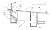
図1において、構築物8の防水する位置に受け枠15を設け、該受け枠と同じ巾の防水板3を立設した箱型の浮体2を載置したピット1を地中に埋設し、近傍に設けた格子蓋5を嵌めて泥溜まり部6を有する雨水排水桝4と、該ピットとを排水管7で接続する。
この構成により、心無い人達により格子蓋より投げ込まれたタバコの吸殻やガム等の浮くゴミ、沈むゴミ等を、増水してきた水により上下に分離して、故障の原因となるゴミがピットに浸入するのを防止出来るものである。
In FIG. 1, a
With this configuration, floating dust such as cigarette butts and gums thrown from lattice lids by heartless people, and sunk garbage are separated up and down by the water that has increased, and the garbage causing the failure enters the pit. Can be prevented.
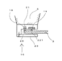
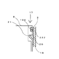
また、図2〜図5において、ピット内の水位の上昇とともに浮体2に立設した防水板3のガイド20がガイド溝18に沿って摺り上がり、浮体2の傾斜屋根11がピット1の上部に備えた傾斜誘導材10に達すると浮体2は斜めに押し上げられる。直後に4箇所のガイド20が受け枠15に設けられたストッパ部21に嵌まり込み、ガイド20はストッパ部21の水平な上壁面を滑って奥の方へ押し込まれる。同時に凸条歯221、222が弾性帯191、192に食い込んで防水板3の初期水密性が確保される。
2 to 5, the
そして、押し寄せてくる水が構築物8に浸入する前の増水初期水位13の段階で防水板3が立ち上がり、水密性も確保されているため、構築物8内の人達はあわてることなく構築物内に居ても良いし、防水板3をまたいで外に出ても良い。
And since the
それから、水位が上昇し、想定増水水位14に達するまでは防水板3に水圧も加わり凸条歯はより強く弾性帯に押圧される。
Then, until the water level rises and reaches the assumed increased
この段階で水が引いたら、ストッパ部21に嵌まり込んでいたガイド20は水位の低下とともに自然にストッパ部21から滑り降りて、浮体2は元のようにピット1の床に載置される。このため深夜、休日等でも操作人員不要で防水板3が作動される。
If water is pulled at this stage, the
それと、大雨洪水注意報等が出た際に、防水板3を前もって立ち上げておくことが可能なように、また、試運転も可能なように、バルブ25を設けて雨水排水桝4へホース等で水を溜めることが出来るようにしておいても良い。この構成により、性能に不安を持つ人は試運転をしてみても良いし、前日の退社前に防水板を立ち上げたままにしておけば、安心して帰宅することも出来る。
In addition, when a heavy rain flood warning is issued, a
それから、想定増水水位14以上に増水しそうな水勢の場合には構築物の内部に居る人が図6の逆L型防水板24を手で持ち上げて対処する。この場合は防水板に凸条歯がないため水密性は少し悪くなる。
Then, in the case of a water flow that is likely to increase above the assumed water increase
なお使用材料としては、防水板や浮体やピットや受け枠は腐食しにくく強度のあるステンレス鋼(SUS304)等とし、弾性帯は耐久性や弾力性に優れたクロロプレンゴムやシリコンゴム、ウレタンゴムや独立気泡の発泡ゴム等が適当であろう。また、ガイド20や傾斜誘導材10等摩擦抵抗の発生する箇所には滑りを良くするためフッ素樹脂等を使用しても良い。
The materials used are waterproof plates, floating bodies, pits and receiving frames, such as stainless steel (SUS304) that is hard to corrode and strong, and the elastic band is chloroprene rubber, silicone rubber, urethane rubber, etc. with excellent durability and elasticity. Closed-cell foamed rubber may be suitable. Further, a fluororesin or the like may be used at a location where frictional resistance is generated, such as the
より安価にするために箱型の浮体は発泡スチロールで作り、出隅部が欠けないようにアングル等で補強しても良い。また、ピットはコンクリート製としても良い。また、ステンレス薄板で製作した浮体に穴があいても中に水を入れないために、または、補強鋼材の代わりに内部を価格の安いウレタンフォームや発泡スチロール等で充填しても良い。 In order to make it cheaper, the box-shaped floating body may be made of foamed polystyrene and reinforced with an angle or the like so that the protruding corner portion is not lost. The pit may be made of concrete. In addition, even if a floating body made of a stainless steel plate has a hole, water may not be filled therein, or the inside may be filled with low-priced urethane foam or polystyrene foam instead of the reinforcing steel material.
浮体の重心が重い防水板の方へ偏心して、浮き上がる際にガイド溝やピットの周壁に防水板や浮体の角が斜めに押圧されて摩擦抵抗が発生するため、2箇所の角にL型鋼よりなるガイドレールを立設し、前記2本のガイド溝と該2本のL型ガイドレールに沿って箱型の浮体がスムーズに上昇するようにしても良い。また、偏心を少なくするように全体の寸法や角度、使用材料等に調整は必要となる。 Since the center of gravity of the floating body is decentered toward the heavy waterproofing board, the corners of the waterproofing board and floating body are pushed diagonally on the peripheral walls of the guide grooves and pits when floating, and friction resistance is generated, so two corners are more than L-shaped steel A guide rail may be erected so that the box-shaped floating body rises smoothly along the two guide grooves and the two L-shaped guide rails. In addition, adjustments are required for the overall dimensions, angles, materials used, etc. so as to reduce eccentricity.
実施の一例を各部の寸法を基に述べてみる。
防水しようとするビルの1階の出入り口の巾を2m、想定増水水位を今までのその地域の経験上1階の床面より例えば0.3mとする。箱型浮体の屋根の傾斜を45度、間口巾を2m、高さを0.7mと0.3m、奥行きを0.4m、防水板の高さを浮体の頂部より0.4m、板厚は1m位までの水圧に耐えるもの、自重を80kgとし、各部の摩擦抵抗を0と想定する。
その際発生する浮力は自重を引くと320kgとなるが、160kgの力で受け枠に押圧されるため充分の水密性が得られる。また、ビルの中の人が防水板をまたいで外へ出る際に、防水板の上に脚を載せたとしても160kgの浮力があるため沈むことはなく安全である。
An example of implementation will be described based on the dimensions of each part.
The width of the first floor entrance and exit of the building to be waterproofed is 2 m, and the assumed water level is set to 0.3 m, for example, from the floor of the first floor based on the experience of the area so far. The slope of the box-type floating roof is 45 degrees, the frontage width is 2 m, the height is 0.7 m and 0.3 m, the depth is 0.4 m, the height of the waterproof board is 0.4 m from the top of the floating body, It is assumed that it can withstand water pressure up to about 1 m, its own weight is 80 kg, and the frictional resistance of each part is 0.
The buoyancy generated at that time is 320 kg when its own weight is pulled, but sufficient water tightness is obtained because it is pressed against the receiving frame by a force of 160 kg. Moreover, even if a person in the building goes outside across the waterproof board, even if he puts his legs on the waterproof board, it is safe because it has 160kg of buoyancy.
1 ピット
2 浮体
3 防水板
4 雨水排水桝
5 格子蓋
6 泥溜まり部
7 排水管
8 構築物床面
9 通路床面
10 傾斜誘導材
11 傾斜屋根
12 点検蓋兼床板(錠付き)
13 増水初期水位
14 想定増水水位
15 受け枠
16 縦枠
17 横枠
18 ガイド溝
191 弾性帯(縦)
192 弾性帯(横)
20 ガイド
21 ストッパ部
221 凸条歯(縦)
222 凸条歯(横)
23 カバー
24 逆L型防水板
25 バルブ
DESCRIPTION OF
13
192 Elastic band (horizontal)
20
222 Convex teeth (horizontal)
23
Claims (2)
Priority Applications (1)
| Application Number | Priority Date | Filing Date | Title |
|---|---|---|---|
| JP2005114060A JP3977848B2 (en) | 2005-04-12 | 2005-04-12 | Simple waterproof board using floating body |
Applications Claiming Priority (1)
| Application Number | Priority Date | Filing Date | Title |
|---|---|---|---|
| JP2005114060A JP3977848B2 (en) | 2005-04-12 | 2005-04-12 | Simple waterproof board using floating body |
Publications (3)
| Publication Number | Publication Date |
|---|---|
| JP2006291580A JP2006291580A (en) | 2006-10-26 |
| JP2006291580A5 JP2006291580A5 (en) | 2006-12-28 |
| JP3977848B2 true JP3977848B2 (en) | 2007-09-19 |
Family
ID=37412429
Family Applications (1)
| Application Number | Title | Priority Date | Filing Date |
|---|---|---|---|
| JP2005114060A Active JP3977848B2 (en) | 2005-04-12 | 2005-04-12 | Simple waterproof board using floating body |
Country Status (1)
| Country | Link |
|---|---|
| JP (1) | JP3977848B2 (en) |
Cited By (6)
| Publication number | Priority date | Publication date | Assignee | Title |
|---|---|---|---|---|
| JP4830054B1 (en) * | 2011-06-08 | 2011-12-07 | 泰則 伊藤 | shutter |
| JP2013060748A (en) * | 2011-09-14 | 2013-04-04 | Yamashita Mitsuo | Waterproof device integrating grating and waterproof plate |
| CN103556930A (en) * | 2013-11-21 | 2014-02-05 | 张建锋 | Sealed bin gate system driven by gears and provided with elastic material at vertical parts |
| CN103556929A (en) * | 2013-11-21 | 2014-02-05 | 黄娟娟 | Sealed bin gate system driven by gears and provided with elastic material in gate plate cavity |
| JP5734489B1 (en) * | 2014-04-04 | 2015-06-17 | 克也 沢田 | Inundation prevention structure |
| JP2015200172A (en) * | 2015-02-23 | 2015-11-12 | 克也 沢田 | Flood preventive structure |
Families Citing this family (6)
| Publication number | Priority date | Publication date | Assignee | Title |
|---|---|---|---|---|
| KR101059553B1 (en) | 2011-02-07 | 2011-08-26 | 범한종합건설 (주) | Apparatus for closing water |
| JP5373951B2 (en) * | 2012-09-03 | 2013-12-18 | 三井造船株式会社 | Evacuation float |
| JP2013047093A (en) * | 2012-09-03 | 2013-03-07 | Mitsui Eng & Shipbuild Co Ltd | Evacuation float |
| CN103603580B (en) * | 2013-11-21 | 2015-05-27 | 陈雪婵 | Sealing bin door system driven by screw and provided with elastic materials on vertical portions |
| JP6176534B2 (en) * | 2014-02-24 | 2017-08-09 | 株式会社 ▲高▼▲橋▼監理 | Flood water stop device |
| JP6895042B2 (en) * | 2019-06-24 | 2021-06-30 | 宗教法人明王寺 | Memorial building and how to lay bones in this memorial building |
-
2005
- 2005-04-12 JP JP2005114060A patent/JP3977848B2/en active Active
Cited By (8)
| Publication number | Priority date | Publication date | Assignee | Title |
|---|---|---|---|---|
| JP4830054B1 (en) * | 2011-06-08 | 2011-12-07 | 泰則 伊藤 | shutter |
| JP2013060748A (en) * | 2011-09-14 | 2013-04-04 | Yamashita Mitsuo | Waterproof device integrating grating and waterproof plate |
| CN103556930A (en) * | 2013-11-21 | 2014-02-05 | 张建锋 | Sealed bin gate system driven by gears and provided with elastic material at vertical parts |
| CN103556929A (en) * | 2013-11-21 | 2014-02-05 | 黄娟娟 | Sealed bin gate system driven by gears and provided with elastic material in gate plate cavity |
| CN103556930B (en) * | 2013-11-21 | 2015-04-08 | 张建锋 | Sealed bin gate system driven by gears and provided with elastic material at vertical parts |
| CN103556929B (en) * | 2013-11-21 | 2015-04-22 | 黄娟娟 | Sealed bin gate system driven by gears and provided with elastic material in gate plate cavity |
| JP5734489B1 (en) * | 2014-04-04 | 2015-06-17 | 克也 沢田 | Inundation prevention structure |
| JP2015200172A (en) * | 2015-02-23 | 2015-11-12 | 克也 沢田 | Flood preventive structure |
Also Published As
| Publication number | Publication date |
|---|---|
| JP2006291580A (en) | 2006-10-26 |
Similar Documents
| Publication | Publication Date | Title |
|---|---|---|
| JP3977848B2 (en) | Simple waterproof board using floating body | |
| US6623209B1 (en) | Automatic flood gate | |
| JP4472749B2 (en) | Tide protection device and tide protection structure | |
| CN202249014U (en) | Flood control board of underground garage | |
| US7744310B2 (en) | Hydrostatically operated variable height bulkhead | |
| JP2003253912A (en) | Water-level follow-up type rise-fall gate device | |
| JP3532462B2 (en) | Buoyancy floor water stop device | |
| JP6187217B2 (en) | Waterproof door device | |
| JP2000319857A (en) | Tide preventing apparatus | |
| KR101402200B1 (en) | Waterproof plate closing device | |
| JP3195948U (en) | Water stop device | |
| JPS6149013A (en) | Floating box type tide gate | |
| JP2619605B2 (en) | Tide prevention device | |
| JP6176534B2 (en) | Flood water stop device | |
| CN110616998A (en) | Flood-proof device and flood-proof system for building entrance | |
| KR100528615B1 (en) | Structure of drainpipe protection flowing backward | |
| JP3717454B2 (en) | Drainage structure of floating type flood control device | |
| JP6516946B1 (en) | Multiple water blocking wall | |
| JP5990370B2 (en) | Waterproof board device | |
| JP2021099011A (en) | Flood disaster resisting facility with flood resisting wall | |
| JP7257720B2 (en) | Water stop unit | |
| JP7203413B2 (en) | Water stop unit | |
| JP7125138B2 (en) | Water stop device | |
| JP3088346U (en) | Floating type flood control device | |
| JP2020143503A (en) | Waterproof door and waterproof method |
Legal Events
| Date | Code | Title | Description |
|---|---|---|---|
| A521 | Written amendment |
Free format text: JAPANESE INTERMEDIATE CODE: A523 Effective date: 20061109 |
|
| A621 | Written request for application examination |
Free format text: JAPANESE INTERMEDIATE CODE: A621 Effective date: 20061109 |
|
| A871 | Explanation of circumstances concerning accelerated examination |
Free format text: JAPANESE INTERMEDIATE CODE: A871 Effective date: 20061109 |
|
| A975 | Report on accelerated examination |
Free format text: JAPANESE INTERMEDIATE CODE: A971005 Effective date: 20061204 |
|
| A131 | Notification of reasons for refusal |
Free format text: JAPANESE INTERMEDIATE CODE: A131 Effective date: 20061212 |
|
| A521 | Written amendment |
Free format text: JAPANESE INTERMEDIATE CODE: A523 Effective date: 20070131 |
|
| A131 | Notification of reasons for refusal |
Free format text: JAPANESE INTERMEDIATE CODE: A131 Effective date: 20070313 |
|
| A521 | Written amendment |
Free format text: JAPANESE INTERMEDIATE CODE: A523 Effective date: 20070322 |
|
| TRDD | Decision of grant or rejection written | ||
| A01 | Written decision to grant a patent or to grant a registration (utility model) |
Free format text: JAPANESE INTERMEDIATE CODE: A01 Effective date: 20070605 |
|
| FPAY | Renewal fee payment (event date is renewal date of database) |
Free format text: PAYMENT UNTIL: 20100629 |
|
| R150 | Certificate of patent or registration of utility model |
Free format text: JAPANESE INTERMEDIATE CODE: R150 |
|
| FPAY | Renewal fee payment (event date is renewal date of database) |
Free format text: PAYMENT UNTIL: 20100629 |
|
| FPAY | Renewal fee payment (event date is renewal date of database) |
Free format text: PAYMENT UNTIL: 20100629 |
|
| FPAY | Renewal fee payment (event date is renewal date of database) |
Free format text: PAYMENT UNTIL: 20100629 |
|
| FPAY | Renewal fee payment (event date is renewal date of database) |
Free format text: PAYMENT UNTIL: 20100629 Year of fee payment: 3 |


