JP3954875B2 - Refrigerant circuit device - Google Patents
Refrigerant circuit device Download PDFInfo
- Publication number
- JP3954875B2 JP3954875B2 JP2002068883A JP2002068883A JP3954875B2 JP 3954875 B2 JP3954875 B2 JP 3954875B2 JP 2002068883 A JP2002068883 A JP 2002068883A JP 2002068883 A JP2002068883 A JP 2002068883A JP 3954875 B2 JP3954875 B2 JP 3954875B2
- Authority
- JP
- Japan
- Prior art keywords
- refrigerant
- pressure
- rotary compression
- compression element
- flow rate
- Prior art date
- Legal status (The legal status is an assumption and is not a legal conclusion. Google has not performed a legal analysis and makes no representation as to the accuracy of the status listed.)
- Expired - Fee Related
Links
Images

Classifications
-
- F—MECHANICAL ENGINEERING; LIGHTING; HEATING; WEAPONS; BLASTING
- F04—POSITIVE - DISPLACEMENT MACHINES FOR LIQUIDS; PUMPS FOR LIQUIDS OR ELASTIC FLUIDS
- F04C—ROTARY-PISTON, OR OSCILLATING-PISTON, POSITIVE-DISPLACEMENT MACHINES FOR LIQUIDS; ROTARY-PISTON, OR OSCILLATING-PISTON, POSITIVE-DISPLACEMENT PUMPS
- F04C18/00—Rotary-piston pumps specially adapted for elastic fluids
- F04C18/30—Rotary-piston pumps specially adapted for elastic fluids having the characteristics covered by two or more of groups F04C18/02, F04C18/08, F04C18/22, F04C18/24, F04C18/48, or having the characteristics covered by one of these groups together with some other type of movement between co-operating members
- F04C18/34—Rotary-piston pumps specially adapted for elastic fluids having the characteristics covered by two or more of groups F04C18/02, F04C18/08, F04C18/22, F04C18/24, F04C18/48, or having the characteristics covered by one of these groups together with some other type of movement between co-operating members having the movement defined in group F04C18/08 or F04C18/22 and relative reciprocation between the co-operating members
- F04C18/356—Rotary-piston pumps specially adapted for elastic fluids having the characteristics covered by two or more of groups F04C18/02, F04C18/08, F04C18/22, F04C18/24, F04C18/48, or having the characteristics covered by one of these groups together with some other type of movement between co-operating members having the movement defined in group F04C18/08 or F04C18/22 and relative reciprocation between the co-operating members with vanes reciprocating with respect to the outer member
- F04C18/3562—Rotary-piston pumps specially adapted for elastic fluids having the characteristics covered by two or more of groups F04C18/02, F04C18/08, F04C18/22, F04C18/24, F04C18/48, or having the characteristics covered by one of these groups together with some other type of movement between co-operating members having the movement defined in group F04C18/08 or F04C18/22 and relative reciprocation between the co-operating members with vanes reciprocating with respect to the outer member the inner and outer member being in contact along one line or continuous surfaces substantially parallel to the axis of rotation
- F04C18/3564—Rotary-piston pumps specially adapted for elastic fluids having the characteristics covered by two or more of groups F04C18/02, F04C18/08, F04C18/22, F04C18/24, F04C18/48, or having the characteristics covered by one of these groups together with some other type of movement between co-operating members having the movement defined in group F04C18/08 or F04C18/22 and relative reciprocation between the co-operating members with vanes reciprocating with respect to the outer member the inner and outer member being in contact along one line or continuous surfaces substantially parallel to the axis of rotation the surfaces of the inner and outer member, forming the working space, being surfaces of revolution
-
- F—MECHANICAL ENGINEERING; LIGHTING; HEATING; WEAPONS; BLASTING
- F04—POSITIVE - DISPLACEMENT MACHINES FOR LIQUIDS; PUMPS FOR LIQUIDS OR ELASTIC FLUIDS
- F04C—ROTARY-PISTON, OR OSCILLATING-PISTON, POSITIVE-DISPLACEMENT MACHINES FOR LIQUIDS; ROTARY-PISTON, OR OSCILLATING-PISTON, POSITIVE-DISPLACEMENT PUMPS
- F04C23/00—Combinations of two or more pumps, each being of rotary-piston or oscillating-piston type, specially adapted for elastic fluids; Pumping installations specially adapted for elastic fluids; Multi-stage pumps specially adapted for elastic fluids
- F04C23/001—Combinations of two or more pumps, each being of rotary-piston or oscillating-piston type, specially adapted for elastic fluids; Pumping installations specially adapted for elastic fluids; Multi-stage pumps specially adapted for elastic fluids of similar working principle
-
- F—MECHANICAL ENGINEERING; LIGHTING; HEATING; WEAPONS; BLASTING
- F04—POSITIVE - DISPLACEMENT MACHINES FOR LIQUIDS; PUMPS FOR LIQUIDS OR ELASTIC FLUIDS
- F04C—ROTARY-PISTON, OR OSCILLATING-PISTON, POSITIVE-DISPLACEMENT MACHINES FOR LIQUIDS; ROTARY-PISTON, OR OSCILLATING-PISTON, POSITIVE-DISPLACEMENT PUMPS
- F04C23/00—Combinations of two or more pumps, each being of rotary-piston or oscillating-piston type, specially adapted for elastic fluids; Pumping installations specially adapted for elastic fluids; Multi-stage pumps specially adapted for elastic fluids
- F04C23/008—Hermetic pumps
Description
【0001】
【発明の属する技術分野】
本発明は、密閉容器内に電動要素と、この電動要素にて駆動される第1及び第2の回転圧縮要素を備え、第1の回転圧縮要素で圧縮された冷媒を第2の回転圧縮要素で圧縮する多段圧縮式ロータリコンプレッサを使用した冷媒回路装置に関するものである。
【0002】
従来のこの種冷媒回路装置、特に内部中間圧型の多段圧縮式ロータリコンプレッサを用いた冷媒回路装置では、多段圧縮式ロータリコンプレッサの第1の回転圧縮要素の吸込ポートから冷媒ガスがシリンダの低圧室側に吸入され、ローラとベーンの動作により圧縮されて中間圧となりシリンダの高圧室側より吐出ポート、吐出消音室を経て密閉容器内に吐出される。そして、この密閉容器内の冷媒ガスは第2の回転圧縮要素の吸込ポートからシリンダの低圧室側に吸入され、ローラとベーンの動作により2段目の圧縮が行われて高温高圧の冷媒ガスとなり、高圧室側より吐出ポート、吐出消音室を経て冷媒回路装置を構成するガスクーラなどの放熱器に流入し、放熱して加熱作用を発揮した後、膨張弁(減圧装置)で絞られて蒸発器に入り、そこで吸熱して蒸発し、その後、第1の回転圧縮要素に吸入されるサイクルを繰り返す。
【0003】
【発明が解決しようとする課題】
係る多段圧縮式ロータリコンプレッサにおいて、高低圧差の大きい冷媒、例えば二酸化炭素(CO2)を冷媒として用いた場合、高圧となる第2の回転圧縮要素の冷媒吐出側で12MPaGに達し、一方、低段側となる第1の回転圧縮要素で8MPaGとなり、これが密閉容器内の中間圧となる。尚、第1の回転圧縮要素の吸込圧力(低圧)は4MPaG程度である。
【0004】
このような多段圧縮式ロータリコンプレッサでは、外気温が高くなって冷媒の蒸発温度が高くなると、第1の回転圧縮要素の吸込圧力も上昇してくる。そのため、第1の回転圧縮要素の冷媒吐出側の圧力(1段目吐出圧力)も高くなってしまい、第2の回転圧縮要素の冷媒吐出側の圧力(2段目吐出圧力)より上昇して、中間圧と高圧との圧力逆転が生じる危険性がある。このような状況となると、第2の回転圧縮要素のベーン飛びが発生し、第2の回転圧縮要素の運転が不安定となる問題が生じる。また、密閉容器内の圧力も高くなるため、密閉容器の許容限界を超えてしまうと云う問題もあった。
【0005】
本発明は、係る技術的課題を解決するために成されたものであり、多段圧縮式ロータリコンプレッサを使用する冷媒回路装置において、第1の回転圧縮要素の冷媒吐出側の圧力の異常上昇を防止することを目的とする。
【0006】
【課題を解決するための手段】
即ち、本発明は、密閉容器内に電動要素と、この電動要素にて駆動される第1及び第2の回転圧縮要素を備え、第1の回転圧縮要素で圧縮された冷媒を第2の回転圧縮要素で圧縮する多段圧縮式ロータリコンプレッサと、この多段圧縮式ロータリコンプレッサの第2の回転圧縮要素から吐出された冷媒が流入するガスクーラと、このガスクーラの出口側に接続された減圧装置と、この減圧装置の出口側に接続された蒸発器とを備えて構成され、この蒸発器から出た冷媒を第1の回転圧縮要素にて圧縮する冷媒回路装置であって、第1の回転圧縮要素から吐出された冷媒を蒸発器に供給するためのバイパス回路と、このバイパス回路を流れる冷媒の流量を制御可能な流量制御弁と、この流量制御弁及び減圧装置を制御する制御手段とを備え、該制御手段は、常には流量制御弁を閉じており、第1の回転圧縮要素の冷媒吐出側の圧力上昇に応じて、当該流量制御弁により前記バイパス回路を流れる冷媒流量を増大させるようにしたので、第1の回転圧縮要素の冷媒吐出側の圧力が上昇した場合には、流量制御弁により第1の回転圧縮要素の吐出冷媒をバイパス回路を介して蒸発器に逃がすことが可能となる。これにより、例えば高外気温時などに第1の回転圧縮要素の冷媒吐出側の圧力が異常に上昇してしまう不都合を未然に回避することができるようになる。
【0007】
また、請求項2の発明では上記に加えて、第1の回転圧縮要素で圧縮された冷媒ガスは密閉容器内に吐出され、第2の回転圧縮要素はこの密閉容器内の冷媒ガスを吸引すると共に、制御手段は、密閉容器内の圧力が所定圧力になった場合に、流量制御弁を開放するので、例えば密閉容器内の圧力が当該密閉容器の許容圧力に近づいた場合に流量制御弁を開放するものとすれば、第1の回転圧縮要素の冷媒吐出側の圧力上昇により、密閉容器内の圧力が密閉容器の圧力の許容限界を超えてしまう不都合も未然に回避することができるようになるものである。
【0008】
更に、請求項3の発明では請求項1の発明に加えて、制御手段は、第1の回転圧縮要素の冷媒吐出側の圧力が第2の回転圧縮要素の冷媒吐出側の圧力より高くなった場合、若しくは第2の回転圧縮要素の冷媒吐出側の圧力に近づいた場合に、流量制御弁を開放するものとしたので、第1の回転圧縮要素の冷媒吐出側と第2の回転圧縮要素の冷媒吐出側との間の圧力逆転を回避し、第2の回転圧縮要素が動作不安定に陥る不都合を未然に回避することができるようになるものである。
【0009】
特に、請求項4の発明では上記に加えて制御手段は、蒸発器の除霜時に減圧装置と流量制御弁を全開とするようにしたので、蒸発器に生じた着霜を第1の回転圧縮要素で圧縮された冷媒ガスと、第2の回転圧縮要素で圧縮された冷媒ガスの双方で除霜することができるようになり、蒸発器に成長した着霜をより効果的に除霜しながら、除霜中における第1の回転圧縮要素の冷媒吐出側と第2の回転圧縮要素の冷媒吐出側との間の圧力逆転も回避することができるようになるものである。
【0010】
【発明の実施の形態】
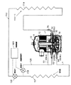
次に、図面に基づき本発明の実施形態を詳述する。図1は本発明に使用する多段圧縮式ロータリコンプレッサの実施例として、第1及び第2の回転圧縮要素32、34を備えた内部中間圧型多段(2段)圧縮式ロータリコンプレッサ10の縦断面図を示している。
【0011】
この図において、10は二酸化炭素(CO2)を冷媒として使用する内部中間圧型の多段圧縮式ロータリコンプレッサで、この多段圧縮式ロータリコンプレッサ10は鋼板からなる円筒状の密閉容器12と、この密閉容器12の内部空間の上側に配置収納された電動要素14、及びこの電動要素14の下側に配置され、電動要素14の回転軸16により駆動される第1の回転圧縮要素32(1段目)、第2の回転圧縮要素34(2段目)からなる回転圧縮機構部18にて構成されている。
【0012】
密閉容器12は、底部をオイル溜めとし、電動要素14と回転圧縮機構部18を収納する容器本体12Aと、この容器本体12Aの上部開口を閉塞する略椀状のエンドキャップ(蓋体)12Bとで構成されている。更に、このエンドキャップ12Bの上面中心には円形状の取付孔12Dが形成されており、この取付孔12Dには電動要素14に電力を供給するためのターミナル(配線を省略)20が溶接固定されている。
【0013】
前記電動要素14は、密閉容器12の上部空間の内周面に沿って環状に取り付けられたステータ22と、このステータ22の内側に若干の隙間を設けて挿入配置されたロータ24とからなり、このロータ24には中心を通り鉛直方向に延びる回転軸16が固定されている。
【0014】
ステータ22は、ドーナッツ状の電磁鋼板を積層した積層体26と、この積層体26の歯部に直巻き(集中巻き)方式により巻装されたステータコイル28とにより構成されている。また、ロータ24は電磁鋼板の積層体30内に永久磁石MGを挿入して構成されている。
【0015】
前記第1の回転圧縮要素32と第2の回転圧縮要素34との間には中間仕切板36が狭持されている。即ち、第1の回転圧縮要素32と第2の回転圧縮要素34は、中間仕切板36と、この中間仕切板36の上下に配置されたシリンダ38、40と、この上下シリンダ38、40内を180度の位相差を有して回転軸16に設けた上下偏心部42、44に嵌合されて偏心回転する上下ローラ46、48と、この上下ローラ46、48に当接して上下シリンダ38、40内をそれぞれ低圧室側と高圧室側に区画する上下ベーン50、52と、上シリンダ38の上側の開口面及び下シリンダ40の下側の開口面を閉塞して回転軸16の軸受けを兼用する支持部材としての上部支持部材54及び下部支持部材56にて構成される。
【0016】
また、上部支持部材54及び下部支持部材56には、図示しない吸込ポートにて上下シリンダ38、40の内部とそれぞれ連通する吸込通路60(上側の吸込通路は図示せず)と、上部支持部材54及び下部支持部材56の凹陥部を壁としてのカバーによって閉塞することにより形成された吐出消音室62、64とが設けられている。即ち、吐出消音室62は吐出消音室62を画成する壁としての上部カバー66、吐出消音室64は吐出消音室64を画成する壁としての下部カバー68にて閉塞される。そして、上部カバー66の上方には、上部カバー66と所定間隔を存して、電動要素14が設けられている。
【0017】
尚、吐出消音室64と密閉容器12内とは、上下シリンダ38、40や中間仕切板36を貫通する図示しない連通路にて連通されており、連通路の上端には中間突出管121が立設され、この中間吐出管121から第1の回転圧縮要素32で圧縮された中間圧の冷媒ガスが密閉容器12内に吐出される。
【0018】
ここで、冷媒としては地球環境にやさしく、可燃性及び毒性等を考慮して自然冷媒である前述した二酸化炭素(CO2)を使用し、潤滑油としてのオイルは、例えば鉱物油(ミネラルオイル)、アルキルベンゼン油、エーテル油、エステル油、PAG(ポリアルキルグリコール)等既存のオイルが使用される。
【0019】
密閉容器12の容器本体12Aの側面には、上部支持部材54と下部支持部材56の吸込通路60(上側の吸込通路は図示せず)、吐出消音室62、上部カバー66の上方(電動要素14の下方に略対応する位置)に対応する位置に、スリーブ141、142、143及び144がそれぞれ溶接固定されている。スリーブ141と142は上下に隣接すると共に、スリーブ143はスリーブ141の略対角線上にある。また、スリーブ144はスリーブ141と略90度ずれた位置にある。
【0020】
そして、スリーブ141内には上シリンダ38に冷媒ガスを導入するための冷媒通路としての冷媒導入管92の一端が挿入接続され、この冷媒導入管92の一端は上シリンダ38の図示しない吸込通路と連通する。この冷媒導入管92は密閉容器12の上方を通過してスリーブ144に至り、他端はスリーブ144内に挿入接続されて密閉容器12内と連通する。
【0021】
また、スリーブ142内には下シリンダ40に冷媒ガスを導入するための冷媒導入管94の一端が挿入接続され、この冷媒導入管94の一端は下シリンダ40の吸込通路60と連通する。この冷媒導入管94の他端は図示しないアキュムレータの下端に接続されている。また、スリーブ143内には冷媒吐出管96が挿入接続され、この冷媒導入管96の一端は吐出消音室62と連通する。
【0022】
前記アキュムレータは吸込冷媒の気液分離を行うタンクであり、密閉容器12の容器本体12Aの上部側面に溶接固定されたブラケット147に図示しないアキュムレータ側のブラケットを介して取り付けられている。
【0023】
次に、図2は本発明を適用した冷媒回路装置の実施例としての給湯装置153の冷媒回路図を示している。上述した多段圧縮式ロータリコンプレッサ10は図2に示す給湯装置153の冷媒回路の一部を構成する。
【0024】
即ち、多段圧縮式ロータリコンプレッサ10の冷媒吐出管96はガスクーラ154の入口に接続しており、このガスクーラ154は水を加熱して温水を生成するため、給湯装置153の図示しない貯湯タンクに設けられている。ガスクーラ154を出た配管は減圧装置としての膨張弁(第1の電子式膨張弁)156を経て蒸発器157の入口に至り、蒸発器157の出口は前記アキュムレータ(図2では示さない)を介して冷媒導入管94に接続される。
【0025】
また、密閉容器12内の冷媒を第2の回転圧縮要素34に導入するための冷媒導入管(冷媒通路)92の途中からは、第1の回転圧縮要素32で圧縮された冷媒ガスを蒸発器157に供給するためのバイパス回路としてのバイパス配管158が分岐して設けられている。そして、このバイパス配管158は、流量制御弁(第2の電子式膨張弁)159を介し、膨張弁156と蒸発器157の間の配管に接続されている。
【0026】
尚、前記流量制御弁159は、バイパス配管158を通って蒸発器157に供給される冷媒の流量を制御するために設けられたものであり、この流量制御弁159の開度は全閉から全開の間で制御手段としての制御装置160により制御される。また、前述した膨張弁156の開度も全開を含めて前記制御装置160により制御される。
【0027】
ここで、第1の回転圧縮要素32と第2の回転圧縮要素34の冷媒吐出側の圧力は外気温による影響を受けて変化する。特に、第1の回転圧縮要素32の吸込圧力は外気温が高くなると上昇するため、第1の回転圧縮要素32の冷媒吐出側の圧力も外気温の上昇に伴って高くなり、最終的には第1の回転圧縮要素32の吐出圧力が第2の回転圧縮要素34の冷媒吐出側の圧力を越えてしまう場合もある。
【0028】
制御装置160は、例えば図示しない外気温度センサー等により外気温を検出する機能を備えると共に、このような外気温と、第1の回転圧縮要素32の吸込圧力(低圧)、第1の回転圧縮要素32の冷媒吐出側の圧力(中間圧)、第2の回転圧縮要素34の冷媒吐出側の圧力(高圧)との相関関係を予め保有しており、外気温に基づいて第1の回転圧縮要素32の冷媒吐出側の圧力(中間圧)及び第2の回転圧縮要素34の冷媒吐出側の圧力を推定することにより、流量制御弁159の開度を制御する。
【0029】
即ち、外気温度センサーの検出により外気温が上昇して第1の回転圧縮要素32の冷媒吐出側の圧力が第2の回転圧縮要素34の冷媒吐出側の圧力に達し、若しくは、近づいたと判断した場合、制御装置160により流量制御弁159は全閉状態から開放し始めると共に、当該外気温から予測された第1の回転圧縮要素32の冷媒吐出側の圧力上昇に応じて徐々に開度を増大させる。
【0030】
流量制御弁159が開放されると、第1の回転圧縮要素32で圧縮され、密閉容器12内に吐出された冷媒ガスの一部は、冷媒導入管92からバイパス配管158を通って、蒸発器157に供給されるようになる。また、前記外気温から推定された第1の回転圧縮要素32の冷媒吐出側の圧力上昇に応じて制御装置160により流量制御弁159は更に開放されるため、バイパス配管158を通って蒸発器157に供給される冷媒の流量は増大する。即ち、外気温の上昇に伴い制御装置160により流量制御弁159を介して蒸発器157に供給する冷媒の流量を増大させることができるようになる。
【0031】
これにより、高外気温時に異常上昇した中間圧の冷媒ガスを蒸発器157に逃がすことで、中間圧の冷媒ガスの圧力を下げることができるようになり、中間圧と高圧の圧力逆転を防ぐことができるようになる。それにより第2の回転圧縮要素34のベーン飛びが生じて動作が不安定となったり、ベーン50の異常摩耗や騒音が発生する不都合を未然に回避することができるようになり、コンプレッサの信頼性の向上を図ることができるようになる。
【0032】
また、除霜運転時になると制御装置160により流量制御弁159及び膨張弁156が全開とされる。これにより、第2の回転圧縮要素34で圧縮され、ガスクーラ154を通過し、制御装置160により全開とされた膨張弁156を通って供給される高圧の冷媒ガスに加えて、第1の回転圧縮要素32で圧縮された中間圧の冷媒ガスも蒸発器157に供給することができるようになるので、蒸発器157に発生した着霜を、より効果的に除霜することことができるようになる。また、除霜中における第2の回転圧縮要素34の冷媒吐出側と第1の回転圧縮要素32の冷媒吐出側との間の圧力逆転も防止されるようになる。
【0033】
以上の構成で次に動作を説明する。尚、通常の加熱運転時において流量制御弁159は制御装置160により閉じられており、膨張弁156は制御装置160により減圧作用を発揮できるように開閉制御される。
【0034】
そして、ターミナル20及び図示されない配線を介して電動要素14のステータコイル28に通電されると、電動要素14が起動してロータ24が回転する。この回転により回転軸16と一体に設けた上下偏心部42、44に嵌合された上下ローラ46、48が上下シリンダ38、40内を偏心回転する。
【0035】
これにより、冷媒導入管94及び下部支持部材56に形成された吸込通路60を経由して、図示しない吸込ポートから下シリンダ40の低圧室側に吸入された低圧の冷媒ガスは、ローラ48とベーン52の動作により圧縮されて中間圧となり、下シリンダ40の高圧室側より図示しない吐出ポート、下部支持部材56に形成された吐出消音室64から図示しない連通路を経て中間吐出管121から密閉容器12内に吐出される。これによって、密閉容器12内は中間圧となる。
【0036】
ここで、外気温が低く第1の回転圧縮要素32の冷媒吐出側の圧力も低い状況では、前述の如く制御装置160により流量制御弁159は閉じられているので、中間圧の冷媒ガスはスリーブ144の冷媒導入管92から出て、上部支持部材54に形成された吸込通路58を経由し、図示しない吸込ポートから上シリンダ38の低圧室側に吸入される。
【0037】
一方、外気温が上昇して制御装置160により第1の回転圧縮要素32の冷媒吐出側の圧力が第2の回転圧縮要素34の冷媒吐出側の圧力に達し、若しくは近づいたと推定されると、流量制御弁159が前述の如く徐々に開かれるので、第1の回転圧縮要素32の冷媒吐出側の冷媒ガスの一部がスリーブ144の冷媒導入管92からバイパス配管158通り、流量制御弁159を介し、蒸発器157に供給される。また、外気温が更に上昇した場合には、制御装置160により流量制御弁159が更に開放されて、バイパス配管158を通過する冷媒ガスの流量が増加する。これにより、密閉容器12内の中間圧の冷媒ガスの圧力は低下するので、第1の回転圧縮要素32と第2の回転圧縮要素34それぞれの冷媒吐出側の圧力における逆転現象は回避される。
【0038】
一方、外気温が例えば所定温度に低下すると、制御装置160により流量制御弁159が閉じられ、密閉容器12内の中間圧の冷媒ガスは全てスリーブ144の冷媒導入管92から出て、上部支持部材54に形成された吸込通路58を経由して図示しない吸込ポートから上シリンダ38の低圧室側に吸入されるようになる。
【0039】
第2の回転圧縮要素34に吸入された中間圧の冷媒ガスは、ローラ46とベーン50の動作により2段目の圧縮が行われて高温高圧の冷媒ガスとなり、高圧室側から図示しない吐出ポートを通り上部支持部材54に構成された吐出消音室62、冷媒吐出管96を経由してガスクーラ154内に流入する。このときの冷媒温度は略+100℃まで上昇しており、係る高温高圧の冷媒ガスはガスクーラ154から放熱し、貯湯タンク内の水を加熱して約+90℃の温水を生成する。
【0040】
このガスクーラ154において冷媒自体は冷却され、ガスクーラ154を出る。そして、膨張弁156で減圧された後、蒸発器157に流入して蒸発し(このときに周囲から吸熱する)、図示しないアキュムレータを経て冷媒導入管94から第1の回転圧縮要素32内に吸い込まれるサイクルを繰り返す。
【0041】
また、このような加熱運転で蒸発器157に着霜が生成すると、制御装置160は定期的に或いは任意の指示操作に基づいて膨張弁156及び流量制御弁159を全開として蒸発器157の除霜運転を実行する。これにより、第2の回転圧縮要素34から吐出された高温高圧の冷媒ガスは冷媒導入管96、ガスクーラ154、膨張弁156(全開状態)を経て流れるものと、第1の回転圧縮要素32から吐出された密閉容器12内の冷媒ガスは冷媒導入管92、バイパス配管158、流量制御弁159(全開状態)を経て、膨張弁156の下流側に流れるものとの両方の流れにより、何れも減圧されること無く直接蒸発器157に流入する。係る高温冷媒ガスの流入によって蒸発器157は加熱され、着霜は融解除去されていく。
【0042】
係る除霜運転は、例えば蒸発器157の所定の除霜終了温度、時間などにより終了する。制御装置160は除霜が終了すると、流量制御弁159を閉じると共に、膨張弁156も通常の減圧作用が発揮できるように制御し、通常の加熱運転に復帰することになる。
【0043】
このように、第1の回転圧縮要素32から吐出された冷媒を蒸発器157に供給するためのバイパス配管158と、このバイパス配管158を流れる冷媒の流量を制御可能な流量制御弁159と、この流量制御弁159及び減圧装置としての膨張弁156を制御する制御装置160とを備え、この制御装置160は、常には流量制御弁159を閉じており、第1の回転圧縮要素32の冷媒吐出側の圧力上昇に応じて、当該流量制御弁159によりバイパス配管158を流れる冷媒流量を増大させるようにしたので、中間圧と高圧の圧力逆転を回避することができるようになり、第2の回転圧縮要素34の不安定な運転状況を回避することができるようになるため、コンプレッサの信頼性の向上を図ることができるようになる。
【0044】
即ち、制御装置160は、第1の回転圧縮要素32の冷媒吐出側の圧力が第2の回転圧縮要素34の冷媒吐出側の圧力に近づいた場合に、流量制御弁159を開放するものとしたので、中間圧と高圧の圧力逆転をより確実に回避することができるようになるものである。
【0045】
特に、制御装置160は、蒸発器157の除霜時に膨張弁156と流量制御弁159を全開とするようにしたので、蒸発器157に生じた着霜を中間圧の冷媒ガスと第2の回転圧縮要素34で圧縮された冷媒ガスとの両方で除霜することができるようになり、蒸発器157に発生した着霜をより効果的に除霜することができるようになると共に、第2の回転圧縮要素34における吸込と吐出の間で圧力逆転が発生する不都合も回避できるようになる。
【0046】
尚、実施例で制御装置160が図示しない外気温度センサーにより外気温を検出することによって第1の回転圧縮要素32の冷媒吐出側の圧力及び第2の回転圧縮要素34の冷媒吐出側の圧力を推定したが、第1の回転圧縮要素32の冷媒吸入側に圧力センサーを設けて、当該圧力センサーにより第1の回転圧縮要素32の冷媒吸入側の圧力を検出して第1の回転圧縮要素32の冷媒吐出側の圧力及び第2の回転圧縮要素34の冷媒吐出側の圧力を推定するものであっても差し支えない。また、各圧縮要素32、34の冷媒吐出側の圧力を直接検出して制御するものであってもよい。
【0047】
また、第1の回転圧縮要素32の冷媒吐出側の圧力が第2の回転圧縮要素34の冷媒吐出側の圧力に達した場合、若しくは、第2の回転圧縮要素34の冷媒吐出側の圧力に近づいた場合に流量制御弁159の開閉を制御するものとしたが、それに限らず、制御装置160が所定圧力になった場合、例えば密閉容器12内の圧力が当該密閉容器12の許容圧力に達した場合、若しくは、当該許容圧力に近づいた場合に、流量制御弁159を開放するようにしてもよい。係る場合には、第1の回転圧縮要素32の冷媒吐出側の圧力上昇により、密閉容器12内の圧力が密閉容器12の圧力の許容限界を超えてしまう不都合も未然に回避することができるようになるので、中間圧の上昇により密閉容器12の破壊やガスリークが発生する不都合を回避可能となる。
【0048】
尚、実施例では冷媒として二酸化炭素を使用したが、これに限らず二酸化炭素のような高低圧差の大きい冷媒を用いても本発明は有効である。
【0049】
更に、実施例では多段圧縮式ロータリコンプレッサ10を給湯装置153の冷媒回路装置に用いたが、これに限らず、室内の暖房用などに用いても本発明は有効である。
【0050】
【発明の効果】
以上詳述した如く本発明によれば、密閉容器内に電動要素と、この電動要素にて駆動される第1及び第2の回転圧縮要素を備え、第1の回転圧縮要素で圧縮された冷媒を第2の回転圧縮要素で圧縮する多段圧縮式ロータリコンプレッサと、この多段圧縮式ロータリコンプレッサの第2の回転圧縮要素から吐出された冷媒が流入するガスクーラと、このガスクーラの出口側に接続された減圧装置と、この減圧装置の出口側に接続された蒸発器とを備えて構成され、この蒸発器から出た冷媒を第1の回転圧縮要素にて圧縮する冷媒回路装置において、第1の回転圧縮要素から吐出された冷媒を蒸発器に供給するためのバイパス回路と、このバイパス回路を流れる冷媒の流量を制御可能な流量制御弁と、この流量制御弁及び減圧装置を制御する制御手段とを備え、該制御手段は、常には流量制御弁を閉じており、第1の回転圧縮要素の冷媒吐出側の圧力上昇に応じて、当該流量制御弁により前記バイパス回路を流れる冷媒流量を増大させるようにしたので、第1の回転圧縮要素の冷媒吐出側の圧力が上昇した場合には、流量制御弁により第1の回転圧縮要素の吐出冷媒をバイパス回路を介して蒸発器に逃がすことが可能となる。これにより、例えば高外気温時などに第1の回転圧縮要素の冷媒吐出側の圧力が異常に上昇してしまう不都合を未然に回避することができるようになる。
【0051】
また、請求項2の発明によれば上記に加えて、第1の回転圧縮要素で圧縮された冷媒ガスは密閉容器内に吐出され、第2の回転圧縮要素はこの密閉容器内の冷媒ガスを吸引すると共に、制御手段は、密閉容器内の圧力が所定圧力になった場合に、流量制御弁を開放するので、例えば密閉容器内の圧力が当該密閉容器の許容圧力に近づいた場合に流量制御弁を開放するものとすれば、第1の回転圧縮要素の冷媒吐出側の圧力上昇により、密閉容器内の圧力が密閉容器の圧力の許容限界を超えてしまう不都合も未然に回避することができるようになるものである。
【0052】
更に、請求項3の発明によれば請求項1の発明に加えて、制御手段は、第1の回転圧縮要素の冷媒吐出側の圧力が第2の回転圧縮要素の冷媒吐出側の圧力より高くなった場合、若しくは第2の回転圧縮要素の冷媒吐出側の圧力に近づいた場合に、流量制御弁を開放するものとしたので、第1の回転圧縮要素の冷媒吐出側と第2の回転圧縮要素の冷媒吐出側との間の圧力逆転を回避し、第2の回転圧縮要素が動作不安定に陥る不都合を未然に回避することができるようになるものである。
【0053】
特に、請求項4の発明によれば上記に加えて制御手段は、蒸発器の除霜時に減圧装置と流量制御弁を全開とするようにしたので、蒸発器に生じた着霜を第1の回転圧縮要素で圧縮された冷媒ガスと、第2の回転圧縮要素で圧縮された冷媒ガスの双方で除霜することができるようになり、蒸発器に成長した着霜をより効果的に除霜しながら、除霜中における第1の回転圧縮要素の冷媒吐出側と第2の回転圧縮要素の冷媒吐出側との間の圧力逆転も回避することができるようになるものである。
【図面の簡単な説明】
【図1】本発明に適応する実施例の多段圧縮式ロータリコンプレッサの縦断面図である。
【図2】本発明を適応した冷媒回路装置の実施例としての給湯装置の冷媒回路図である。
【符号の説明】
10 多段圧縮式ロータリコンプレッサ
12 密閉容器
18 回転圧縮機構部
32 第1の回転圧縮要素
34 第2の回転圧縮要素
92 冷媒導入管
94 冷媒導入管
96 冷媒吐出管
153 給湯装置(冷媒回路装置)
154 ガスクーラ
156 膨張弁
157 蒸発器
158 バイパス配管(バイパス回路)
159 流量制御弁
160 制御装置(制御手段)[0001]
BACKGROUND OF THE INVENTION
The present invention includes an electric element in a hermetic container and first and second rotary compression elements driven by the electric element, and the refrigerant compressed by the first rotary compression element is used as the second rotary compression element. The present invention relates to a refrigerant circuit device that uses a multi-stage compression rotary compressor that compresses at the same time.
[0002]
In this type of conventional refrigerant circuit device, particularly a refrigerant circuit device using an internal intermediate pressure type multi-stage compression rotary compressor, the refrigerant gas flows from the suction port of the first rotary compression element of the multi-stage compression rotary compressor to the low pressure chamber side of the cylinder And is compressed by the operation of the roller and the vane to become an intermediate pressure, and is discharged from the high pressure chamber side of the cylinder into the sealed container through the discharge port and the discharge silencer chamber. Then, the refrigerant gas in the sealed container is sucked from the suction port of the second rotary compression element to the low pressure chamber side of the cylinder, and the second stage compression is performed by the operation of the roller and the vane to become a high temperature and high pressure refrigerant gas. From the high-pressure chamber side, after passing through the discharge port and discharge silencer chamber, it flows into a heat radiator such as a gas cooler constituting the refrigerant circuit device, radiates heat and exerts a heating action, and is then throttled by an expansion valve (decompression device). And then absorbs heat and evaporates, and then repeats the cycle of being drawn into the first rotary compression element.
[0003]
[Problems to be solved by the invention]
In such a multistage compression rotary compressor, a refrigerant having a large high-low pressure difference, such as carbon dioxide (CO 2 ) Is used as a refrigerant, the pressure reaches 12 MPaG on the refrigerant discharge side of the second rotary compression element, which is at a high pressure, and 8 MPaG on the first rotary compression element on the low stage side, which is the intermediate pressure in the sealed container. It becomes. The suction pressure (low pressure) of the first rotary compression element is about 4 MPaG.
[0004]
In such a multistage compression rotary compressor, when the outside air temperature increases and the refrigerant evaporation temperature increases, the suction pressure of the first rotary compression element also increases. For this reason, the pressure on the refrigerant discharge side of the first rotary compression element (first-stage discharge pressure) also increases, and rises above the pressure on the refrigerant discharge side of the second rotary compression element (second-stage discharge pressure). There is a risk that a pressure reversal between the intermediate pressure and the high pressure occurs. In such a situation, vane jumping of the second rotary compression element occurs, causing a problem that the operation of the second rotary compression element becomes unstable. Further, since the pressure in the sealed container is increased, there is a problem that the allowable limit of the sealed container is exceeded.
[0005]
The present invention has been made to solve such technical problems, and prevents an abnormal increase in pressure on the refrigerant discharge side of the first rotary compression element in a refrigerant circuit device using a multistage compression rotary compressor. The purpose is to do.
[0006]
[Means for Solving the Problems]
That is, the present invention includes an electric element in a hermetic container and first and second rotary compression elements driven by the electric element, and the refrigerant compressed by the first rotary compression element is second rotated. A multi-stage compression rotary compressor that compresses by a compression element, a gas cooler into which refrigerant discharged from the second rotary compression element of the multi-stage compression rotary compressor flows, a decompression device connected to the outlet side of the gas cooler, and An evaporator connected to the outlet side of the decompression device, and a refrigerant circuit device that compresses the refrigerant discharged from the evaporator by the first rotary compression element, from the first rotary compression element A bypass circuit for supplying the discharged refrigerant to the evaporator, a flow rate control valve capable of controlling the flow rate of the refrigerant flowing through the bypass circuit, and a control means for controlling the flow rate control valve and the pressure reducing device, The control means always closes the flow rate control valve, and according to the pressure increase on the refrigerant discharge side of the first rotary compression element, the flow rate control valve increases the flow rate of the refrigerant flowing through the bypass circuit. When the pressure on the refrigerant discharge side of the first rotary compression element increases, the discharge refrigerant of the first rotary compression element can be released to the evaporator via the bypass circuit by the flow rate control valve. As a result, for example, it is possible to avoid inconvenience that the pressure on the refrigerant discharge side of the first rotary compression element rises abnormally, for example, when the outside air temperature is high.
[0007]
In the invention of claim 2, in addition to the above, the refrigerant gas compressed by the first rotary compression element is discharged into the hermetic container, and the second rotary compression element sucks the refrigerant gas in the hermetic container. At the same time, the control means opens the flow control valve when the pressure in the sealed container reaches a predetermined pressure. For example, when the pressure in the sealed container approaches the allowable pressure of the sealed container, the control means opens the flow control valve. If it is opened, the inconvenience that the pressure in the closed container exceeds the allowable limit of the pressure of the closed container due to the pressure increase on the refrigerant discharge side of the first rotary compression element can be avoided. It will be.
[0008]
Further, in the invention of claim 3, in addition to the invention of claim 1, the control means is configured such that the pressure on the refrigerant discharge side of the first rotary compression element is higher than the pressure on the refrigerant discharge side of the second rotary compression element. In this case, or when the pressure on the refrigerant discharge side of the second rotary compression element is approached, the flow control valve is opened, so that the refrigerant discharge side of the first rotary compression element and the second rotary compression element It is possible to avoid the inversion of the pressure between the refrigerant discharge side and the inconvenience that the second rotary compression element becomes unstable in operation.
[0009]
In particular, in the invention of claim 4, in addition to the above, the control means opens the pressure reducing device and the flow rate control valve at the time of defrosting of the evaporator. It becomes possible to defrost both the refrigerant gas compressed by the element and the refrigerant gas compressed by the second rotary compression element, and more effectively defrosting the frost that has grown on the evaporator In addition, pressure reversal between the refrigerant discharge side of the first rotary compression element and the refrigerant discharge side of the second rotary compression element during defrosting can be avoided.
[0010]
DETAILED DESCRIPTION OF THE INVENTION
Next, embodiments of the present invention will be described in detail with reference to the drawings. FIG. 1 is a longitudinal sectional view of an internal intermediate pressure type multi-stage (two-stage) compression
[0011]
In this figure, 10 is carbon dioxide (CO 2 ) Is used as a refrigerant. The multi-stage compression
[0012]
The sealed
[0013]
The electric element 14 includes a
[0014]
The
[0015]
An
[0016]
The upper support member 54 and the
[0017]
The
[0018]
Here, the above-mentioned carbon dioxide (CO), which is a natural refrigerant in consideration of flammability and toxicity, is friendly to the global environment as the refrigerant. 2 As the lubricating oil, existing oils such as mineral oil (mineral oil), alkylbenzene oil, ether oil, ester oil, and PAG (polyalkyl glycol) are used.
[0019]
On the side surface of the container
[0020]
One end of a
[0021]
In addition, one end of a
[0022]
The accumulator is a tank that performs gas-liquid separation of the suction refrigerant, and is attached to a
[0023]
Next, FIG. 2 shows a refrigerant circuit diagram of a hot
[0024]
That is, the
[0025]
Further, from the middle of the refrigerant introduction pipe (refrigerant passage) 92 for introducing the refrigerant in the
[0026]
The flow
[0027]
Here, the pressure on the refrigerant discharge side of the first
[0028]
The
[0029]
That is, it is determined that the outside air temperature has risen due to the detection of the outside air temperature sensor and the pressure on the refrigerant discharge side of the first
[0030]
When the
[0031]
As a result, the intermediate-pressure refrigerant gas that has risen abnormally at high outside air temperature is allowed to escape to the
[0032]
Further, when the defrosting operation is started, the
[0033]
Next, the operation of the above configuration will be described. During normal heating operation, the
[0034]
When the
[0035]
As a result, the low-pressure refrigerant gas sucked into the low-pressure chamber side of the
[0036]
Here, in a situation where the outside air temperature is low and the pressure on the refrigerant discharge side of the first
[0037]
On the other hand, when the outside air temperature rises and the
[0038]
On the other hand, when the outside air temperature falls to, for example, a predetermined temperature, the flow
[0039]
The intermediate-pressure refrigerant gas sucked into the second
[0040]
In this
[0041]
Further, when frost is generated in the
[0042]
Such a defrosting operation is ended, for example, by a predetermined defrosting end temperature and time of the
[0043]
Thus, the
[0044]
That is, the
[0045]
In particular, since the
[0046]
In the embodiment, when the
[0047]
Further, when the pressure on the refrigerant discharge side of the first
[0048]
In the embodiment, carbon dioxide is used as the refrigerant. However, the present invention is not limited to this, and the present invention is effective even when a refrigerant having a large high-low pressure difference such as carbon dioxide is used.
[0049]
Furthermore, in the embodiment, the multistage
[0050]
【The invention's effect】
As described above in detail, according to the present invention, the refrigerant is provided with the electric element in the hermetic container and the first and second rotary compression elements driven by the electric element, and is compressed by the first rotary compression element. Is connected to the outlet side of the gas cooler, the gas cooler into which the refrigerant discharged from the second rotary compression element of the multistage compression rotary compressor flows, and the gas cooler In a refrigerant circuit device comprising a decompression device and an evaporator connected to the outlet side of the decompression device, and compressing refrigerant discharged from the evaporator by a first rotary compression element, the first rotation A bypass circuit for supplying the refrigerant discharged from the compression element to the evaporator, a flow rate control valve capable of controlling the flow rate of the refrigerant flowing through the bypass circuit, and a control for controlling the flow rate control valve and the pressure reducing device The control means always closes the flow rate control valve, and in response to a rise in pressure on the refrigerant discharge side of the first rotary compression element, the flow rate control valve controls the flow rate of the refrigerant flowing through the bypass circuit. When the pressure on the refrigerant discharge side of the first rotary compression element increases, the refrigerant discharged from the first rotary compression element is released to the evaporator via the bypass circuit by the flow control valve. Is possible. As a result, for example, it is possible to avoid inconvenience that the pressure on the refrigerant discharge side of the first rotary compression element rises abnormally, for example, when the outside air temperature is high.
[0051]
According to the invention of claim 2, in addition to the above, the refrigerant gas compressed by the first rotary compression element is discharged into the sealed container, and the second rotary compression element discharges the refrigerant gas in the closed container. In addition to suction, the control means opens the flow control valve when the pressure in the sealed container reaches a predetermined pressure, so that, for example, the flow control is performed when the pressure in the sealed container approaches the allowable pressure of the sealed container. If the valve is opened, it is possible to avoid the disadvantage that the pressure in the closed container exceeds the allowable limit of the pressure of the closed container due to the pressure increase on the refrigerant discharge side of the first rotary compression element. It will be like that.
[0052]
Further, according to the invention of claim 3, in addition to the invention of claim 1, the control means is configured such that the pressure on the refrigerant discharge side of the first rotary compression element is higher than the pressure on the refrigerant discharge side of the second rotary compression element. In this case, or when the pressure on the refrigerant discharge side of the second rotary compression element is approached, the flow control valve is opened, so the refrigerant discharge side of the first rotary compression element and the second rotary compression The pressure reversal between the element and the refrigerant discharge side can be avoided, and the inconvenience that the second rotary compression element becomes unstable in operation can be avoided.
[0053]
In particular, according to the invention of claim 4, in addition to the above, the control means opens the pressure reducing device and the flow rate control valve at the time of defrosting of the evaporator. It becomes possible to defrost both the refrigerant gas compressed by the rotary compression element and the refrigerant gas compressed by the second rotary compression element, and more effectively defrosts the frost that has grown on the evaporator. However, pressure reversal between the refrigerant discharge side of the first rotary compression element and the refrigerant discharge side of the second rotary compression element during defrosting can be avoided.
[Brief description of the drawings]
FIG. 1 is a longitudinal sectional view of a multi-stage compression rotary compressor according to an embodiment applicable to the present invention.
FIG. 2 is a refrigerant circuit diagram of a hot water supply device as an embodiment of a refrigerant circuit device to which the present invention is applied.
[Explanation of symbols]
10 Multi-stage compression rotary compressor
12 Sealed container
18 Rotary compression mechanism
32 First rotary compression element
34 Second rotational compression element
92 Refrigerant introduction pipe
94 Refrigerant introduction pipe
96 Refrigerant discharge pipe
153 Water heater (refrigerant circuit device)
154 Gas cooler
156 expansion valve
157 evaporator
158 Bypass piping (bypass circuit)
159 Flow control valve
160 Control device (control means)
Claims (4)
前記第1の回転圧縮要素から吐出された冷媒を前記蒸発器に供給するためのバイパス回路と、
該バイパス回路を流れる冷媒の流量を制御可能な流量制御弁と、
該流量制御弁及び前記減圧装置を制御する制御手段とを備え、
該制御手段は、常には前記流量制御弁を閉じており、前記第1の回転圧縮要素の冷媒吐出側の圧力上昇に応じて、前記流量制御弁により前記バイパス回路を流れる冷媒流量を増大させることを特徴とする冷媒回路装置。An airtight container is provided with an electric element and first and second rotary compression elements driven by the electric element, and the refrigerant compressed by the first rotary compression element is compressed by the second rotary compression element. A multistage compression rotary compressor, a gas cooler into which refrigerant discharged from the second rotary compression element of the multistage compression rotary compressor flows, a decompression device connected to an outlet side of the gas cooler, and an outlet of the decompression device A refrigerant circuit device configured to compress the refrigerant discharged from the evaporator with the first rotary compression element;
A bypass circuit for supplying refrigerant discharged from the first rotary compression element to the evaporator;
A flow rate control valve capable of controlling the flow rate of the refrigerant flowing through the bypass circuit;
Control means for controlling the flow rate control valve and the pressure reducing device,
The control means always closes the flow rate control valve, and increases the flow rate of refrigerant flowing through the bypass circuit by the flow rate control valve in response to an increase in pressure on the refrigerant discharge side of the first rotary compression element. A refrigerant circuit device.
前記制御手段は、前記密閉容器内の圧力が所定圧力になった場合に、前記流量制御弁を開放することを特徴とする請求項1の冷媒回路装置。The refrigerant gas compressed by the first rotary compression element is discharged into the sealed container, the second rotary compression element sucks the refrigerant gas in the sealed container,
The refrigerant circuit device according to claim 1, wherein the control means opens the flow rate control valve when the pressure in the sealed container becomes a predetermined pressure.
Priority Applications (11)
| Application Number | Priority Date | Filing Date | Title |
|---|---|---|---|
| JP2002068883A JP3954875B2 (en) | 2002-03-13 | 2002-03-13 | Refrigerant circuit device |
| CNB031051715A CN1318760C (en) | 2002-03-13 | 2003-03-05 | Multi-stage compressive rotary compressor and refrigerant return device |
| KR10-2003-0015288A KR20030074372A (en) | 2002-03-13 | 2003-03-12 | Multistage rotary compressor and refrigerant circuit system using the same |
| TW096141470A TWI323774B (en) | 2002-03-13 | 2003-03-13 | Refrigeration circuit system |
| US10/386,672 US6748754B2 (en) | 2002-03-13 | 2003-03-13 | Multistage rotary compressor and refrigeration circuit system |
| EP03251521A EP1344938B1 (en) | 2002-03-13 | 2003-03-13 | Multistage rotary compressor and refrigeration circuit system |
| DK03251521.5T DK1344938T3 (en) | 2002-03-13 | 2003-03-13 | Rotary multistage compressor and cooling circuit system |
| EP10167954.6A EP2233742B1 (en) | 2002-03-13 | 2003-03-13 | Multistage rotary compressor with pressure relief valve |
| AT03251521T ATE510131T1 (en) | 2002-03-13 | 2003-03-13 | MULTI-STAGE ROTARY COMPRESSOR AND COOLER |
| TW092105429A TWI313729B (en) | 2002-03-13 | 2003-03-13 | Multistage rotary compressor |
| EP10167960.3A EP2241758B1 (en) | 2002-03-13 | 2003-03-13 | Refrigeration circuit system with a multistage rotary compressor |
Applications Claiming Priority (1)
| Application Number | Priority Date | Filing Date | Title |
|---|---|---|---|
| JP2002068883A JP3954875B2 (en) | 2002-03-13 | 2002-03-13 | Refrigerant circuit device |
Publications (2)
| Publication Number | Publication Date |
|---|---|
| JP2003269804A JP2003269804A (en) | 2003-09-25 |
| JP3954875B2 true JP3954875B2 (en) | 2007-08-08 |
Family
ID=29199875
Family Applications (1)
| Application Number | Title | Priority Date | Filing Date |
|---|---|---|---|
| JP2002068883A Expired - Fee Related JP3954875B2 (en) | 2002-03-13 | 2002-03-13 | Refrigerant circuit device |
Country Status (1)
| Country | Link |
|---|---|
| JP (1) | JP3954875B2 (en) |
Families Citing this family (4)
| Publication number | Priority date | Publication date | Assignee | Title |
|---|---|---|---|---|
| JP2006161659A (en) * | 2004-12-07 | 2006-06-22 | Hitachi Ltd | Refrigerating cycle device |
| JP4725592B2 (en) * | 2007-05-25 | 2011-07-13 | 株式会社デンソー | Refrigeration cycle equipment |
| JP4725591B2 (en) * | 2007-05-25 | 2011-07-13 | 株式会社デンソー | Refrigeration cycle equipment |
| JP2013015082A (en) * | 2011-07-04 | 2013-01-24 | Fujitsu General Ltd | Two-stage compression rotary compressor |
Family Cites Families (5)
| Publication number | Priority date | Publication date | Assignee | Title |
|---|---|---|---|---|
| JPH03213679A (en) * | 1990-01-19 | 1991-09-19 | Mitsubishi Electric Corp | Multi-cylinder rotary compressor |
| JPH07318179A (en) * | 1994-05-26 | 1995-12-08 | Toshiba Corp | Sealed compressor, and freezer and air conditioner including the compressor |
| JP2000161276A (en) * | 1998-11-30 | 2000-06-13 | Sanyo Electric Co Ltd | Rotary compressor and refrigeration circuit employing same |
| JP4441965B2 (en) * | 1999-06-11 | 2010-03-31 | ダイキン工業株式会社 | Air conditioner |
| JP2003074997A (en) * | 2001-09-04 | 2003-03-12 | Sanyo Electric Co Ltd | Supercritical refrigeration unit |
-
2002
- 2002-03-13 JP JP2002068883A patent/JP3954875B2/en not_active Expired - Fee Related
Also Published As
| Publication number | Publication date |
|---|---|
| JP2003269804A (en) | 2003-09-25 |
Similar Documents
| Publication | Publication Date | Title |
|---|---|---|
| EP2233742B1 (en) | Multistage rotary compressor with pressure relief valve | |
| US20080199325A1 (en) | Compression system, multicylinder rotary compressor, and refrigeration apparatus using the same | |
| KR101738458B1 (en) | High pressure compressor and refrigerating machine having the same | |
| JP2004293813A (en) | Refrigerant cycle device | |
| JP3995570B2 (en) | Refrigerant circuit device | |
| JP4219198B2 (en) | Refrigerant cycle equipment | |
| JP2005003239A (en) | Refrigerant cycling device | |
| JP2009079820A (en) | Refrigerating cycle device | |
| JP2004116957A (en) | Refrigerant cycle system | |
| JP3954875B2 (en) | Refrigerant circuit device | |
| JP4278402B2 (en) | Refrigerant cycle equipment | |
| JP2007146663A (en) | Sealed compressor and refrigerating cycle device | |
| JP3895976B2 (en) | Multistage rotary compressor | |
| JP3983115B2 (en) | Refrigerant circuit using CO2 refrigerant | |
| JP2006022723A (en) | Compression system and refrigerating apparatus using the same | |
| JP4241127B2 (en) | Transcritical refrigerant cycle equipment | |
| JP2004251492A (en) | Refrigerant cycle device | |
| EP2322804B1 (en) | Multiple-stage compressor | |
| JP2004251514A (en) | Refrigerant cycle device | |
| JP2004308489A (en) | Refrigerant cycle apparatus | |
| JP4404708B2 (en) | Compression system and refrigeration system using the same | |
| JP2011027372A (en) | Refrigerating cycle device and heat pump water heater | |
| JP2006022766A (en) | Multi-cylinder rotary compressor | |
| JP2005147562A (en) | Two-stage compression type rotary compressor, and car air conditioner and heat pump type hot water supply apparatus using it | |
| JP2004170043A (en) | Cooling device |
Legal Events
| Date | Code | Title | Description |
|---|---|---|---|
| A621 | Written request for application examination |
Free format text: JAPANESE INTERMEDIATE CODE: A621 Effective date: 20040507 |
|
| A977 | Report on retrieval |
Free format text: JAPANESE INTERMEDIATE CODE: A971007 Effective date: 20070129 |
|
| TRDD | Decision of grant or rejection written | ||
| A01 | Written decision to grant a patent or to grant a registration (utility model) |
Free format text: JAPANESE INTERMEDIATE CODE: A01 Effective date: 20070402 |
|
| A61 | First payment of annual fees (during grant procedure) |
Free format text: JAPANESE INTERMEDIATE CODE: A61 Effective date: 20070427 |
|
| FPAY | Renewal fee payment (event date is renewal date of database) |
Free format text: PAYMENT UNTIL: 20110511 Year of fee payment: 4 |
|
| FPAY | Renewal fee payment (event date is renewal date of database) |
Free format text: PAYMENT UNTIL: 20120511 Year of fee payment: 5 |
|
| FPAY | Renewal fee payment (event date is renewal date of database) |
Free format text: PAYMENT UNTIL: 20130511 Year of fee payment: 6 |
|
| FPAY | Renewal fee payment (event date is renewal date of database) |
Free format text: PAYMENT UNTIL: 20130511 Year of fee payment: 6 |
|
| FPAY | Renewal fee payment (event date is renewal date of database) |
Free format text: PAYMENT UNTIL: 20140511 Year of fee payment: 7 |
|
| LAPS | Cancellation because of no payment of annual fees |