JP3945872B2 - Pre-plating method - Google Patents
Pre-plating method Download PDFInfo
- Publication number
- JP3945872B2 JP3945872B2 JP26930297A JP26930297A JP3945872B2 JP 3945872 B2 JP3945872 B2 JP 3945872B2 JP 26930297 A JP26930297 A JP 26930297A JP 26930297 A JP26930297 A JP 26930297A JP 3945872 B2 JP3945872 B2 JP 3945872B2
- Authority
- JP
- Japan
- Prior art keywords
- plating
- pressure
- medium
- liquid
- substrate
- Prior art date
- Legal status (The legal status is an assumption and is not a legal conclusion. Google has not performed a legal analysis and makes no representation as to the accuracy of the status listed.)
- Expired - Fee Related
Links
Images


Classifications
-
- H—ELECTRICITY
- H01—ELECTRIC ELEMENTS
- H01L—SEMICONDUCTOR DEVICES NOT COVERED BY CLASS H10
- H01L21/00—Processes or apparatus adapted for the manufacture or treatment of semiconductor or solid state devices or of parts thereof
- H01L21/02—Manufacture or treatment of semiconductor devices or of parts thereof
- H01L21/04—Manufacture or treatment of semiconductor devices or of parts thereof the devices having at least one potential-jump barrier or surface barrier, e.g. PN junction, depletion layer or carrier concentration layer
- H01L21/18—Manufacture or treatment of semiconductor devices or of parts thereof the devices having at least one potential-jump barrier or surface barrier, e.g. PN junction, depletion layer or carrier concentration layer the devices having semiconductor bodies comprising elements of Group IV of the Periodic System or AIIIBV compounds with or without impurities, e.g. doping materials
- H01L21/28—Manufacture of electrodes on semiconductor bodies using processes or apparatus not provided for in groups H01L21/20 - H01L21/268
-
- C—CHEMISTRY; METALLURGY
- C23—COATING METALLIC MATERIAL; COATING MATERIAL WITH METALLIC MATERIAL; CHEMICAL SURFACE TREATMENT; DIFFUSION TREATMENT OF METALLIC MATERIAL; COATING BY VACUUM EVAPORATION, BY SPUTTERING, BY ION IMPLANTATION OR BY CHEMICAL VAPOUR DEPOSITION, IN GENERAL; INHIBITING CORROSION OF METALLIC MATERIAL OR INCRUSTATION IN GENERAL
- C23C—COATING METALLIC MATERIAL; COATING MATERIAL WITH METALLIC MATERIAL; SURFACE TREATMENT OF METALLIC MATERIAL BY DIFFUSION INTO THE SURFACE, BY CHEMICAL CONVERSION OR SUBSTITUTION; COATING BY VACUUM EVAPORATION, BY SPUTTERING, BY ION IMPLANTATION OR BY CHEMICAL VAPOUR DEPOSITION, IN GENERAL
- C23C18/00—Chemical coating by decomposition of either liquid compounds or solutions of the coating forming compounds, without leaving reaction products of surface material in the coating; Contact plating
- C23C18/16—Chemical coating by decomposition of either liquid compounds or solutions of the coating forming compounds, without leaving reaction products of surface material in the coating; Contact plating by reduction or substitution, e.g. electroless plating
- C23C18/1601—Process or apparatus
- C23C18/1633—Process of electroless plating
- C23C18/1675—Process conditions
- C23C18/168—Control of temperature, e.g. temperature of bath, substrate
-
- C—CHEMISTRY; METALLURGY
- C23—COATING METALLIC MATERIAL; COATING MATERIAL WITH METALLIC MATERIAL; CHEMICAL SURFACE TREATMENT; DIFFUSION TREATMENT OF METALLIC MATERIAL; COATING BY VACUUM EVAPORATION, BY SPUTTERING, BY ION IMPLANTATION OR BY CHEMICAL VAPOUR DEPOSITION, IN GENERAL; INHIBITING CORROSION OF METALLIC MATERIAL OR INCRUSTATION IN GENERAL
- C23C—COATING METALLIC MATERIAL; COATING MATERIAL WITH METALLIC MATERIAL; SURFACE TREATMENT OF METALLIC MATERIAL BY DIFFUSION INTO THE SURFACE, BY CHEMICAL CONVERSION OR SUBSTITUTION; COATING BY VACUUM EVAPORATION, BY SPUTTERING, BY ION IMPLANTATION OR BY CHEMICAL VAPOUR DEPOSITION, IN GENERAL
- C23C18/00—Chemical coating by decomposition of either liquid compounds or solutions of the coating forming compounds, without leaving reaction products of surface material in the coating; Contact plating
- C23C18/16—Chemical coating by decomposition of either liquid compounds or solutions of the coating forming compounds, without leaving reaction products of surface material in the coating; Contact plating by reduction or substitution, e.g. electroless plating
- C23C18/1601—Process or apparatus
- C23C18/1619—Apparatus for electroless plating
-
- C—CHEMISTRY; METALLURGY
- C23—COATING METALLIC MATERIAL; COATING MATERIAL WITH METALLIC MATERIAL; CHEMICAL SURFACE TREATMENT; DIFFUSION TREATMENT OF METALLIC MATERIAL; COATING BY VACUUM EVAPORATION, BY SPUTTERING, BY ION IMPLANTATION OR BY CHEMICAL VAPOUR DEPOSITION, IN GENERAL; INHIBITING CORROSION OF METALLIC MATERIAL OR INCRUSTATION IN GENERAL
- C23C—COATING METALLIC MATERIAL; COATING MATERIAL WITH METALLIC MATERIAL; SURFACE TREATMENT OF METALLIC MATERIAL BY DIFFUSION INTO THE SURFACE, BY CHEMICAL CONVERSION OR SUBSTITUTION; COATING BY VACUUM EVAPORATION, BY SPUTTERING, BY ION IMPLANTATION OR BY CHEMICAL VAPOUR DEPOSITION, IN GENERAL
- C23C18/00—Chemical coating by decomposition of either liquid compounds or solutions of the coating forming compounds, without leaving reaction products of surface material in the coating; Contact plating
- C23C18/16—Chemical coating by decomposition of either liquid compounds or solutions of the coating forming compounds, without leaving reaction products of surface material in the coating; Contact plating by reduction or substitution, e.g. electroless plating
- C23C18/1601—Process or apparatus
- C23C18/1633—Process of electroless plating
- C23C18/1635—Composition of the substrate
- C23C18/1644—Composition of the substrate porous substrates
-
- C—CHEMISTRY; METALLURGY
- C23—COATING METALLIC MATERIAL; COATING MATERIAL WITH METALLIC MATERIAL; CHEMICAL SURFACE TREATMENT; DIFFUSION TREATMENT OF METALLIC MATERIAL; COATING BY VACUUM EVAPORATION, BY SPUTTERING, BY ION IMPLANTATION OR BY CHEMICAL VAPOUR DEPOSITION, IN GENERAL; INHIBITING CORROSION OF METALLIC MATERIAL OR INCRUSTATION IN GENERAL
- C23C—COATING METALLIC MATERIAL; COATING MATERIAL WITH METALLIC MATERIAL; SURFACE TREATMENT OF METALLIC MATERIAL BY DIFFUSION INTO THE SURFACE, BY CHEMICAL CONVERSION OR SUBSTITUTION; COATING BY VACUUM EVAPORATION, BY SPUTTERING, BY ION IMPLANTATION OR BY CHEMICAL VAPOUR DEPOSITION, IN GENERAL
- C23C18/00—Chemical coating by decomposition of either liquid compounds or solutions of the coating forming compounds, without leaving reaction products of surface material in the coating; Contact plating
- C23C18/16—Chemical coating by decomposition of either liquid compounds or solutions of the coating forming compounds, without leaving reaction products of surface material in the coating; Contact plating by reduction or substitution, e.g. electroless plating
- C23C18/1601—Process or apparatus
- C23C18/1633—Process of electroless plating
- C23C18/1675—Process conditions
- C23C18/1682—Control of atmosphere
-
- C—CHEMISTRY; METALLURGY
- C23—COATING METALLIC MATERIAL; COATING MATERIAL WITH METALLIC MATERIAL; CHEMICAL SURFACE TREATMENT; DIFFUSION TREATMENT OF METALLIC MATERIAL; COATING BY VACUUM EVAPORATION, BY SPUTTERING, BY ION IMPLANTATION OR BY CHEMICAL VAPOUR DEPOSITION, IN GENERAL; INHIBITING CORROSION OF METALLIC MATERIAL OR INCRUSTATION IN GENERAL
- C23C—COATING METALLIC MATERIAL; COATING MATERIAL WITH METALLIC MATERIAL; SURFACE TREATMENT OF METALLIC MATERIAL BY DIFFUSION INTO THE SURFACE, BY CHEMICAL CONVERSION OR SUBSTITUTION; COATING BY VACUUM EVAPORATION, BY SPUTTERING, BY ION IMPLANTATION OR BY CHEMICAL VAPOUR DEPOSITION, IN GENERAL
- C23C18/00—Chemical coating by decomposition of either liquid compounds or solutions of the coating forming compounds, without leaving reaction products of surface material in the coating; Contact plating
- C23C18/16—Chemical coating by decomposition of either liquid compounds or solutions of the coating forming compounds, without leaving reaction products of surface material in the coating; Contact plating by reduction or substitution, e.g. electroless plating
- C23C18/1601—Process or apparatus
- C23C18/1633—Process of electroless plating
- C23C18/1675—Process conditions
- C23C18/1685—Process conditions with supercritical condition, e.g. chemical fluid deposition
-
- B—PERFORMING OPERATIONS; TRANSPORTING
- B05—SPRAYING OR ATOMISING IN GENERAL; APPLYING FLUENT MATERIALS TO SURFACES, IN GENERAL
- B05D—PROCESSES FOR APPLYING FLUENT MATERIALS TO SURFACES, IN GENERAL
- B05D2401/00—Form of the coating product, e.g. solution, water dispersion, powders or the like
- B05D2401/90—Form of the coating product, e.g. solution, water dispersion, powders or the like at least one component of the composition being in supercritical state or close to supercritical state
-
- H—ELECTRICITY
- H05—ELECTRIC TECHNIQUES NOT OTHERWISE PROVIDED FOR
- H05K—PRINTED CIRCUITS; CASINGS OR CONSTRUCTIONAL DETAILS OF ELECTRIC APPARATUS; MANUFACTURE OF ASSEMBLAGES OF ELECTRICAL COMPONENTS
- H05K3/00—Apparatus or processes for manufacturing printed circuits
- H05K3/0085—Apparatus for treatments of printed circuits with liquids not provided for in groups H05K3/02 - H05K3/46; conveyors and holding means therefor
- H05K3/0088—Apparatus for treatments of printed circuits with liquids not provided for in groups H05K3/02 - H05K3/46; conveyors and holding means therefor for treatment of holes
Description
【0001】
【発明の属する技術分野】
本発明は半導体の次世代配線技術である金属配線形成技術に関し、特に基板上に形成された微細溝にめっきにより金属の埋め込みを行うためのめっき前処理方法に関するものである。
【0002】
【従来の技術】
半導体を用いた集積回路において、回路配線材料にはアルミニウムが多く用いられてきた。アルミニウム配線は、スパッタリング法(Sputtering)により基板にアルミニウム膜を付けた後レジスト形成によりパターニングを行い、エッチングにより配線形成される。回路の高度集積化に伴い、配線幅がより狭く形成されることが要求されるようになってきたが、アルミニウムの材料特性上諸問題が生じる様になってきた。他の金属材料による配線形成には従来の上記回路形成が困難な場合があり、配線用の溝や穴をあらかじめ形成し、化学気相成長法(Chemical Vapor Deposition:以下CVD法)、スパッタリング法やめっき法などの手法により金属を溝の中に埋め込み、その後表面を化学機械研磨(Chemical Mechanical Polishing : 以下CMP)で表面研磨し、回路配線を形成する方法がとられてきた。
【0003】
めっき法は金属の膜付け方法としては広く用いられており、多くの特長をもつ。図7は基本的なめっき装置を示す。めっき槽1内のめっき液9中で被めっき基板2を取り付けたカソード電極3およびアノード電極4が対向して設けられ、めっき操作中にめっき液9を攪拌する攪拌器11が設けられている。めっきの前処理としては被めっき基板の洗浄又はエッチング等が行われていた。
【0004】
【発明が解決しようとする課題】
めっき法は他のプロセスに比べて、プロセスコストが安い、純度の高い材料が得られる、熱的影響の少ない低温プロセスが可能となる等の特長があるが、ウェーハ基板上に形成された微細溝にめっき液が流入しにくいので、アスペクト比の大きい、深い微細溝でへの金属埋め込みはほとんど行われていないのが実状であった。
【0005】
微細溝が形成された被めっき基板をめっき液に浸漬させても、通常その微細溝には空気が残留し、図6のように、完全にはめっき液が流入しない。これは被めっき基板のぬれ性やめっきめっき液の表面張力等の影響によるものと考えられ、微細溝の幅が狭くなるほど、その傾向は強くなる。
【0006】
そこで本発明は、ウェーハ基板上にパターン形成された微細溝への良好な金属埋め込みをめっき法により行うため、めっきプロセスとしてめっき液を確実にその微細溝に流入させることのできるめっき用前処理方法を提供することを目的とする。
【0007】
【課題を解決するための手段】
請求項1に記載の発明は、被めっき基板と常温常圧においてめっき液と置換可能な液体である媒質とを容器中に共存させ、前記容器内部を加温・加圧して該容器内部の前記媒質を亜臨界又は超臨界状態に保持した後、前記容器内部の圧力を調整しつつ温度を下げて、前記媒質を気相状態を介することなく常温常圧まで変化させることを特徴とするめっきめっき前処理方法である。
【0008】
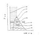
この発明は、物質の超臨界状態を用いるものである。図3に水の飽和蒸気圧を示す。水はこの線上で気液の相変化を起こす。例えば、図4に示すように、シリンダに1kgの水を入れて加熱すると、その温度と圧力との関係で、液相、液と蒸気との混相、そして気相との状態に分かれる。これを、圧力と比容積とのグラフで表すと、図5となる。ある圧力以上では気相と液相とが界面を持った共存状態とはならず、等質な単相で蒸発現象を伴わずに変化する。このような変化を起こす開始点を臨界点といい、これを超える状態を超臨界状態、これに近い状態を亜臨界状態という。
【0009】
液体は温度の上昇と共に表面張力が低下し、臨界点で零になる。そして、臨界点では気液両相に分かれることなく等質な相となる。また例えば、臨界圧以上の圧力を持つ液体を等圧のもとで加熱すると、蒸発の現象を伴わずに気液両相に分かれることなく気体に変化させることができる。また逆に、気体を加熱すると同時に圧力を臨界圧以上にした後、等圧のもとで冷却すると凝縮の現象を伴わずに液化することができる。
【0010】
めっき液もしくはその溶媒である水を22MPa(226kgf/cm2)以上の圧力かつ374℃(647K)以上の温度にすると、臨界状態もしくは超臨界状態になる。この状態では、空気の主成分である窒素および酸素も超臨界状態にあり、水および空気からなる容器内は均一な単相状態となる。このような状態中に、表面に微細溝が形成された被めっき基板を置くと、微細溝内に残留していた空気は容器内に拡散し、微細溝内は実質的に水の流体相で満たされる。
【0011】
その後、例えば、圧力を一定に保ったまま温度を下げると、表面張力の影響を受けることなく、被めっき基板上に形成された微細溝等の窪みに水もしくはめっき液を気泡を生ずることなく流入させることができる。
【0012】
請求項2に記載の発明は、前記媒質は、水又はめっき液であることを特徴とする請求項1に記載のめっき前処理方法である。めっきの前処理工程に使うものとして、一般的でめっき工程にも全く害がない。高温高圧では水、酸素および窒素が単一流体相となる状態を経るため、表面張力の影響を受けることなく、被めっき基板上に形成された微細窪みに水もしくはめっき液を気泡なく注入することができる。
【0013】
請求項3に記載の発明は、前記媒質は、水より臨界圧力又は臨界温度の少なくとも一方が低いものであることを特徴とする請求項1に記載のめっき前処理方法である。これにより、水の臨界点より低い温度と圧力で、基板上の微細溝により簡単な条件で液体を充填させ、その後にめっき液と置換させればよい。従って、媒質としてはめっき液との置換性と、めっき工程における無害性が望まれる。
【0014】
請求項4に記載の発明は、前記媒質は、アルコールであることを特徴とする請求項3に記載のめっき前処理方法である。これにより、低い温度と圧力とで基板上の微細溝に液を注入させることができ、めっき液に本前処理済みめっき基板を浸漬させるのみで前記液とめっき液とを置換させることができる。
【0015】
請求項5に記載の発明は、前記容器に前記媒質を充満させる前に前記容器内を真空にすることを特徴とする請求項1に記載のめっき前処理方法である。これにより、被めっき基板上に形成された微細窪みに存在する空気等の不凝縮ガスを取り出してから上述プロセスを行うことができるため、より完全に、迅速に微細窪みに水もしくはめっき液を気泡なく注入することができる。
【0016】
容器中にめっき基板を収納した後、前記媒質を液体状態で容器内に導入した後、亜臨界又は超臨界状態にするようにしてもよい。
【0017】
容器中にめっき基板を収納した後、前記媒質を気体状態で容器内に導入した後、亜臨界又は超臨界状態にするようにしてもよい。
【0018】
前記容器内に気体状態の媒質を導入する過程において前記容器内の圧力を1又は複数回圧力変動をさせるようにしてもよい。これにより、被めっき基板上に形成された微細窪みに存在する空気等の不凝縮ガスを取り出してから上述プロセスを行うことができるため、より完全に、迅速に微細窪みに液体を気泡なく流入させることができる。
【0019】
請求項6に記載の発明は、請求項1ないし5のいずれかに記載のめっき前処理方法を行った後にめっきを行い、さらに基板に付着した金属の不要部分を化学機械研磨装置により研磨して除去することを特徴とする基板の加工方法である。
【0020】
【発明の実施の形態】
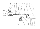
図1は本発明の実施の形態例としてめっき前処理装置の概要を示す図である。この前処理装置は、密閉可能な圧力容器である処理室53と、これに接続された液導入配管55、ガス排出配管57及び液排出配管58とを主な構成要素としている。処理室53には、圧力計7及び圧力スイッチ8が取り付けられ、基板2及び処理室温度調節器78が処理室53に収納されている。
【0021】
液(媒質)導入配管55は、ストレージタンク76、ポンプ74、調整弁71、チェッキ弁75、温度調節器77及び温度検知器6を備えており、処理室53に液を所定の圧力まで加圧して供給することができる。ガス排出配管57は開閉弁23と安全弁36を備えており、処理室53からガスを安全に排出することができる。液排出配管58は、開閉弁24及び調整弁72を備えており、処理室53の液を圧力を管理しながら排出することができる。
【0022】
このような構成の装置を用いて、めっきの前処理工程を行う方法を説明する。図6と同様の微細溝62が形成された基板2を処理室53に収納し、液導入配管55によって処理室53に液を導入すると同時に、ガス排出配管57により空気を排出する。処理室53が液で満たされた後、ガス排出配管57の開閉弁23を閉じ、さらに液導入配管55のポンプ74により処理室53内を加圧して圧力を臨界圧力22MPa(226kgf/cm2)以上にした後、処理室温度調節器78により処理室53内の液温を臨界温度374℃(647K)以上にする。温度上昇に伴う液の体積膨張に対しては液排出配管58の調整弁72を用いて処理室53の液を排出することにより圧力を管理する。
【0023】
このようにして、処理室53内を超臨界状態に保つと、処理室53内の液及び僅かの残留空気は均一の単一相流体となり、基板2上に形成された微細溝62内に液成分を主体とした流体で満たされる。その後、処理室温度調節器78により処理室53内の温度を下げると同時に液導入配管55から液を導入して処理室53の圧力を調節することにより、処理室内の流体を気化させることなく常温常圧の液体にする。以上のようにして、基板2上に形成された微細構62内に液を充填することができる。
【0024】
図2の装置は、本発明の別の実施の形態のめっき前処理装置の概要を示す図である。本装置は、図1に示すめっき前処理装置と略同様であるが、処理室53に高温高圧の蒸気を供給して室内を超臨界状態にするように構成されている点が異なる。すなわち、密閉可能な圧力容器である処理室53には、蒸気(媒質)導入配管91、ガス排出配管57及び液排出配管58が接続されている。処理室53には、圧力計7及び圧力スイッチ8が取り付けられ、基板2及び温度調節器78が処理室53に収納されている。
【0025】
蒸気導入配管91は、ポンプ74、ボイラ79、開閉弁31、調整弁71及び温度調節器80を備えており、処理室53に高温高圧の蒸気及び超臨界状態の蒸気を供給することができる。これにより、処理室53内を気相領域を経て超臨界状態を保持した後、図1の装置と同様に、処理室内の流体を気化することなく常温常圧の液体にすることができる。
【0026】
なお、上記の実施の形態では、媒質の超臨界状態を用いたが、亜臨界状態であってもよい。また、上記では、水又はめっき液を媒質として用いたが、アルコールを用いることにより、より低い温度と圧力で超臨界状態を得ることができる。また、微細溝をアルコールで充填した後、そのままめっき槽のめっき液中に浸漬させれば、めっき液とアルコールが置換されてめっきが行える。
【0027】
また、上記の実施の形態では、1枚の基板を処理するようにしたが、エネルギーの節約や能率の向上の観点からは、複数枚を同時に前処理することが望ましい。その場合は、基板を複数液体中に浸漬した状態で保持できるカセットに収容し、その状態で前処理やめっき槽への移送を行なうとよい。また、連続処理を意識して、前処理室をめっき槽と兼用するようにしてもよい。
【0028】
【発明の効果】
以上説明したように、この発明によれば、媒質の超臨界相の特徴を利用して微細溝にめっき液を浸入させてめっきを行なうことにより、欠陥のない良好な品質で、効率よく行うことができ、従って、ウェーハ基板上にパターン形成された微細溝への良好な金属埋め込みが可能となって、半導体装置の高度の集積化に対応する有用な技術を提供することができる。
【図面の簡単な説明】
【図1】本発明に基づく実施形態のめっき前処理装置の概要図である。
【図2】本発明に基づく実施形態のめっき前処理装置の概要図である。
【図3】水の飽和蒸気圧曲線である。
【図4】相状態の変化を表す概要図である。
【図5】相状態を示すP−v線図である。
【図6】液中にある基板上の微細溝に残留する気泡を示す概要図である。
【図7】一般のめっき装置の概要図である。
【符号の説明】
1 めっき槽
2 被めっき基板
3 カソード電極
4 アノード電極
5 電源
6 温度検知器
7 圧力計
8 圧力スイッチ
9 めっき液
11 撹拌器
23 開閉弁
24 開閉弁
31 開閉弁
36 安全弁
50 蒸気
52 液
53 処理室
55 液導入配管
57 ガス排出配管
58 液排出配管
61 めっき面
62 微細溝
63 気泡
71 調整弁
72 調整弁
73 調整弁
74 ポンプ
75 チェッキ弁
76 ストレージタンク
77 温度調節器
78 処理室温度調節器
79 ボイラ
80 温度調節器
81 シリンダ
82 おもり
83 ピストン
84 液相
85 気液混相
86 気相
87 臨界点
88 最小容積線
89 飽和液線
90 飽和蒸気線
91 蒸気導入配管[0001]
BACKGROUND OF THE INVENTION
The present invention relates to a metal wiring forming technique which is a next-generation wiring technique for semiconductors, and more particularly to a plating pretreatment method for embedding metal in a fine groove formed on a substrate by plating.
[0002]
[Prior art]
In an integrated circuit using a semiconductor, aluminum is often used as a circuit wiring material. Aluminum wiring is formed by etching after forming an aluminum film on a substrate by sputtering and patterning by resist formation. As the circuit is highly integrated, it has been required that the wiring width be made narrower, but various problems have arisen in the material characteristics of aluminum. For wiring formation with other metal materials, the above-mentioned conventional circuit formation may be difficult. Grooves and holes for wiring are formed in advance, chemical vapor deposition (hereinafter referred to as CVD), sputtering, A method has been adopted in which a metal is embedded in a groove by a technique such as plating, and then the surface is polished by chemical mechanical polishing (hereinafter referred to as CMP) to form a circuit wiring.
[0003]
The plating method is widely used as a metal film forming method and has many features. FIG. 7 shows a basic plating apparatus. A cathode electrode 3 and an anode electrode 4 to which the substrate to be plated 2 is attached are provided facing each other in the plating solution 9 in the plating tank 1, and a
[0004]
[Problems to be solved by the invention]
Compared to other processes, the plating method has features such as low process costs, high-purity materials, and low-temperature processes with little thermal influence. However, the fine grooves formed on the wafer substrate Since it is difficult for the plating solution to flow into the metal, the metal is hardly buried in the deep fine grooves having a large aspect ratio.
[0005]
Even if the substrate to be plated on which the fine grooves are formed is immersed in the plating solution, air usually remains in the fine grooves, and the plating solution does not flow completely as shown in FIG. This is considered to be due to the influence of the wettability of the substrate to be plated and the surface tension of the plating solution, and the tendency becomes stronger as the width of the fine groove becomes narrower.
[0006]
Accordingly, the present invention provides a plating pretreatment method capable of reliably flowing a plating solution into a fine groove as a plating process in order to perform good metal embedding in a fine groove patterned on a wafer substrate by a plating method. The purpose is to provide.
[0007]
[Means for Solving the Problems]
In the first aspect of the present invention, a substrate to be plated and a medium that is a liquid that can be replaced with a plating solution at room temperature and normal pressure coexist in a container, and the inside of the container is heated and pressurized to increase the inside of the container. After maintaining the medium in a subcritical or supercritical state, the temperature is lowered while adjusting the pressure inside the container, and the medium is changed to normal temperature and normal pressure without going through the gas phase state. This is a pre-processing method.
[0008]
This invention uses the supercritical state of matter. FIG. 3 shows the saturated vapor pressure of water. Water causes a gas-liquid phase change on this line. For example, as shown in FIG. 4, when 1 kg of water is put into a cylinder and heated, it is divided into a liquid phase, a mixed phase of liquid and vapor, and a gas phase depending on the temperature and pressure. This can be represented by a graph of pressure and specific volume as shown in FIG. Above a certain pressure, the gas phase and the liquid phase do not coexist with an interface, but change in a homogeneous single phase without evaporation. The starting point causing such a change is called a critical point, a state exceeding this is called a supercritical state, and a state close to this is called a subcritical state.
[0009]
As the temperature increases, the surface tension of the liquid decreases and becomes zero at the critical point. And at a critical point, it becomes a homogeneous phase without being separated into both gas-liquid phases. Further, for example, when a liquid having a pressure equal to or higher than the critical pressure is heated under an equal pressure, it can be changed into a gas without being separated into a gas-liquid phase without causing an evaporation phenomenon. Conversely, when the gas is heated and at the same time the pressure is raised above the critical pressure and then cooled under an equal pressure, the gas can be liquefied without the phenomenon of condensation.
[0010]
When the plating solution or water as its solvent is brought to a pressure of 22 MPa (226 kgf / cm 2 ) or higher and a temperature of 374 ° C. (647 K) or higher, it becomes a critical state or a supercritical state. In this state, nitrogen and oxygen, which are the main components of air, are also in a supercritical state, and the inside of the container made of water and air is in a uniform single-phase state. When a substrate to be plated with a fine groove formed on the surface is placed in such a state, the air remaining in the fine groove diffuses into the container, and the fine groove is substantially in a fluid phase of water. It is filled.
[0011]
After that, for example, if the temperature is lowered while keeping the pressure constant, water or the plating solution flows into the depressions such as fine grooves formed on the substrate to be plated without being affected by the surface tension without generating bubbles. Can be made.
[0012]
The invention according to claim 2 is the plating pretreatment method according to claim 1, wherein the medium is water or a plating solution. Generally used as a pre-treatment process for plating, there is no harm in the plating process. Since water, oxygen, and nitrogen pass through a single fluid phase at high temperature and pressure, water or plating solution can be injected without bubbles into the fine depressions formed on the substrate to be plated without being affected by surface tension. Can do.
[0013]
The invention according to claim 3 is the plating pretreatment method according to claim 1, wherein the medium has a critical pressure or a critical temperature lower than that of water. In this way, the liquid is filled in the micro grooves on the substrate under simple conditions at a temperature and pressure lower than the critical point of water, and then replaced with the plating solution. Therefore, the medium is desired to be replaceable with a plating solution and harmless in the plating process.
[0014]
The invention according to claim 4 is the plating pretreatment method according to claim 3, wherein the medium is alcohol. As a result, the liquid can be injected into the fine groove on the substrate at a low temperature and pressure, and the liquid and the plating solution can be replaced only by immersing the pretreated plating substrate in the plating solution.
[0015]
The invention according to
[0016]
After the plated substrate was housed in container, after the medium is introduced into the container in a liquid state, it may be in the subcritical or supercritical state.
[0017]
After the plated substrate was housed in the container, the medium was introduced into the vessel in a gaseous state may be the subcritical or supercritical state.
[0018]
In the course of introducing the medium in a gaseous state the pressure in the vessel may be causing one or more times the pressure fluctuation before Symbol vessel. Thereby, since the above-mentioned process can be performed after taking out the non-condensable gas such as air existing in the fine depression formed on the substrate to be plated, the liquid can flow into the fine depression more completely and quickly without bubbles. be able to.
[0019]
According to a sixth aspect of the present invention, plating is performed after the plating pretreatment method according to any one of the first to fifth aspects of the present invention, and unnecessary portions of the metal adhering to the substrate are polished by a chemical mechanical polishing apparatus. It is a processing method of a board | substrate characterized by removing.
[0020]
DETAILED DESCRIPTION OF THE INVENTION
FIG. 1 is a diagram showing an outline of a plating pretreatment apparatus as an embodiment of the present invention. This pretreatment apparatus includes a
[0021]
The liquid (medium)
[0022]
A method for performing a pretreatment step of plating using the apparatus having such a configuration will be described. The substrate 2 on which the
[0023]
When the inside of the
[0024]
The apparatus of FIG. 2 is a figure which shows the outline | summary of the plating pre-processing apparatus of another embodiment of this invention. This apparatus is substantially the same as the plating pretreatment apparatus shown in FIG. 1 except that the apparatus is configured to supply high-temperature and high-pressure steam to the
[0025]
The
[0026]
In the above embodiment, the supercritical state of the medium is used. However, a subcritical state may be used. In the above, water or a plating solution is used as a medium. However, by using alcohol, a supercritical state can be obtained at a lower temperature and pressure. Further, if the fine groove is filled with alcohol and then immersed in the plating solution in the plating tank as it is, plating can be performed by replacing the plating solution and alcohol.
[0027]
In the above embodiment, one substrate is processed. However, from the viewpoint of saving energy and improving efficiency, it is desirable to pre-process a plurality of substrates simultaneously. In that case, the substrate may be stored in a cassette that can be held in a state of being immersed in a plurality of liquids, and in that state, the substrate may be pretreated or transferred to a plating tank. Further, in consideration of continuous processing, the pretreatment chamber may be used also as a plating tank.
[0028]
【The invention's effect】
As described above, according to the present invention, by performing the plating by infiltrating the plating solution into the fine groove by utilizing the characteristics of the supercritical phase of the medium, it is possible to efficiently perform with good quality without defects. Therefore, it is possible to satisfactorily embed a metal in a fine groove patterned on a wafer substrate, and to provide a useful technique corresponding to a high degree of integration of a semiconductor device.
[Brief description of the drawings]
FIG. 1 is a schematic view of a plating pretreatment apparatus according to an embodiment of the present invention.
FIG. 2 is a schematic diagram of a plating pretreatment apparatus according to an embodiment of the present invention.
FIG. 3 is a saturated vapor pressure curve of water.
FIG. 4 is a schematic diagram showing a change in phase state.
FIG. 5 is a Pv diagram showing a phase state.
FIG. 6 is a schematic view showing bubbles remaining in a fine groove on a substrate in a liquid.
FIG. 7 is a schematic view of a general plating apparatus.
[Explanation of symbols]
DESCRIPTION OF SYMBOLS 1 Plating tank 2 Substrate 3 Cathode electrode 4
Claims (6)
前記容器内部を加温・加圧して該容器内部の前記媒質を亜臨界又は超臨界状態に保持した後、
前記容器内部の圧力を調整しつつ温度を下げて、前記媒質を気相状態を介することなく常温常圧まで変化させることを特徴とするめっき前処理方法。The substrate to be plated and a medium that can be replaced with the plating solution at room temperature and normal pressure coexist in the container,
After holding the medium inside the container in a subcritical or supercritical state by applying heat and pressure inside the container,
A plating pretreatment method characterized by lowering the temperature while adjusting the pressure inside the container to change the medium to normal temperature and normal pressure without going through a gas phase state.
Priority Applications (5)
| Application Number | Priority Date | Filing Date | Title |
|---|---|---|---|
| JP26930297A JP3945872B2 (en) | 1997-09-16 | 1997-09-16 | Pre-plating method |
| KR1019980037903A KR100538301B1 (en) | 1997-09-16 | 1998-09-15 | Substrate Plating Method and Apparatus |
| DE69823952T DE69823952T2 (en) | 1997-09-16 | 1998-09-16 | Method of plating |
| US09/153,895 US6123984A (en) | 1997-09-16 | 1998-09-16 | Method and apparatus for plating a substrate |
| EP98117559A EP0913497B1 (en) | 1997-09-16 | 1998-09-16 | Method for plating a substrate |
Applications Claiming Priority (1)
| Application Number | Priority Date | Filing Date | Title |
|---|---|---|---|
| JP26930297A JP3945872B2 (en) | 1997-09-16 | 1997-09-16 | Pre-plating method |
Publications (2)
| Publication Number | Publication Date |
|---|---|
| JPH1192990A JPH1192990A (en) | 1999-04-06 |
| JP3945872B2 true JP3945872B2 (en) | 2007-07-18 |
Family
ID=17470460
Family Applications (1)
| Application Number | Title | Priority Date | Filing Date |
|---|---|---|---|
| JP26930297A Expired - Fee Related JP3945872B2 (en) | 1997-09-16 | 1997-09-16 | Pre-plating method |
Country Status (5)
| Country | Link |
|---|---|
| US (1) | US6123984A (en) |
| EP (1) | EP0913497B1 (en) |
| JP (1) | JP3945872B2 (en) |
| KR (1) | KR100538301B1 (en) |
| DE (1) | DE69823952T2 (en) |
Families Citing this family (11)
| Publication number | Priority date | Publication date | Assignee | Title |
|---|---|---|---|---|
| US20050205111A1 (en) * | 1999-10-12 | 2005-09-22 | Ritzdorf Thomas L | Method and apparatus for processing a microfeature workpiece with multiple fluid streams |
| WO2001027357A1 (en) * | 1999-10-12 | 2001-04-19 | Semitool, Inc. | Method and apparatus for executing plural processes on a microelectronic workpiece at a single processing station |
| JP4660661B2 (en) * | 2000-02-22 | 2011-03-30 | コスモ石油株式会社 | Plating pretreatment method for plastic, plating method, method for producing plated product, and plating apparatus |
| AU2001275795A1 (en) | 2000-08-24 | 2002-03-04 | Hiroe Asai | Electrochemical treating method such as electroplating and electrochemical reaction device therefor |
| CN101147908A (en) | 2002-05-20 | 2008-03-26 | 松下电器产业株式会社 | Washing method |
| AU2003290858A1 (en) * | 2002-11-12 | 2004-06-03 | The Regents Of The University Of California | Nano-porous fibers and protein membranes |
| US7217749B2 (en) * | 2003-01-20 | 2007-05-15 | Northern Technologies International Corporation | Process for infusing an alkali metal nitrite into a synthetic resinous material |
| US7217750B2 (en) * | 2003-01-20 | 2007-05-15 | Northern Technologies International Corporation | Process for incorporating one or more materials into a polymer composition and products produced thereby |
| JP2004225152A (en) * | 2003-01-27 | 2004-08-12 | Tokyo Electron Ltd | Method for treating substrate and method for manufacturing semiconductor device |
| CN101459050B (en) * | 2007-12-14 | 2013-03-27 | 盛美半导体设备(上海)有限公司 | Method and apparatus for metallic layer front wafer surface presoaking for electrochemical or chemical deposition |
| US10221488B2 (en) * | 2015-09-18 | 2019-03-05 | General Electric Company | Supercritical water method for treating internal passages |
Family Cites Families (6)
| Publication number | Priority date | Publication date | Assignee | Title |
|---|---|---|---|---|
| JP2719782B2 (en) * | 1987-08-19 | 1998-02-25 | イビデン株式会社 | Manufacturing method of multilayer printed wiring board |
| JPH02209729A (en) * | 1989-02-09 | 1990-08-21 | Matsushita Electric Ind Co Ltd | Manufacture of semiconductor device and apparatus for removing foreign substance |
| JPH03127832A (en) * | 1989-10-13 | 1991-05-30 | Matsushita Electric Ind Co Ltd | Manufacture of semiconductor device and drying equipment |
| KR930019861A (en) * | 1991-12-12 | 1993-10-19 | 완다 케이. 덴슨-로우 | Coating method using dense gas |
| JPH07283219A (en) * | 1994-04-13 | 1995-10-27 | Sanyo Electric Co Ltd | Manufacture of semiconductor device |
| JPH09139374A (en) * | 1995-11-15 | 1997-05-27 | Hitachi Ltd | Surface treating method and apparatus and element obtained from them |
-
1997
- 1997-09-16 JP JP26930297A patent/JP3945872B2/en not_active Expired - Fee Related
-
1998
- 1998-09-15 KR KR1019980037903A patent/KR100538301B1/en not_active IP Right Cessation
- 1998-09-16 DE DE69823952T patent/DE69823952T2/en not_active Expired - Fee Related
- 1998-09-16 US US09/153,895 patent/US6123984A/en not_active Expired - Fee Related
- 1998-09-16 EP EP98117559A patent/EP0913497B1/en not_active Expired - Lifetime
Also Published As
| Publication number | Publication date |
|---|---|
| EP0913497A1 (en) | 1999-05-06 |
| DE69823952T2 (en) | 2005-05-12 |
| KR19990029783A (en) | 1999-04-26 |
| JPH1192990A (en) | 1999-04-06 |
| KR100538301B1 (en) | 2006-03-16 |
| DE69823952D1 (en) | 2004-06-24 |
| US6123984A (en) | 2000-09-26 |
| EP0913497B1 (en) | 2004-05-19 |
Similar Documents
| Publication | Publication Date | Title |
|---|---|---|
| US6544585B1 (en) | Method and apparatus for plating a substrate | |
| JP3945872B2 (en) | Pre-plating method | |
| US6286231B1 (en) | Method and apparatus for high-pressure wafer processing and drying | |
| US10199240B2 (en) | Substrate processing method, substrate processing apparatus, and storage medium | |
| WO2003049167A1 (en) | Method of high pressure treatment | |
| JP2003500842A (en) | Temperature controlled gasification of deionized water for megasonic cleaning of semiconductor wafers | |
| US7179000B2 (en) | Method of developing a resist film and a resist development processor | |
| JPH1197409A (en) | Pressure-reduced drying device and drying method for semiconductor device using device thereof | |
| JP3492528B2 (en) | Supercritical drying apparatus and method | |
| JP5066336B2 (en) | High pressure processing apparatus and high pressure processing method | |
| JPH1193000A (en) | Plating method and apparatus therefor | |
| US20220020609A1 (en) | Substrate treating apparatus | |
| JPH11152597A (en) | Plating pretreatment | |
| JPH11181574A (en) | Pretreatment for plating | |
| KR101116644B1 (en) | Method of drying a substrate and apparatus for drying a substrate | |
| KR100626363B1 (en) | wafer drying apparatus | |
| KR20060129790A (en) | Apparatus for substrate cleaning dry | |
| US20220013372A1 (en) | Substrate treating apparatus and substrate treating method | |
| JPH1180990A (en) | Pretreatment apparatus for plating | |
| JPH11200058A (en) | Plating apparatus | |
| TW200822195A (en) | Method for cleaning a substrate | |
| CN109300802A (en) | For drying the device and method of chip | |
| JP2008016548A (en) | High-pressure processing method | |
| KR20110082307A (en) | Apparatus for drying a substrate and method of drying a substrate | |
| JP2001102348A (en) | Substrate treating method and system |
Legal Events
| Date | Code | Title | Description |
|---|---|---|---|
| A977 | Report on retrieval |
Free format text: JAPANESE INTERMEDIATE CODE: A971007 Effective date: 20040623 |
|
| A131 | Notification of reasons for refusal |
Free format text: JAPANESE INTERMEDIATE CODE: A131 Effective date: 20040831 |
|
| A521 | Request for written amendment filed |
Free format text: JAPANESE INTERMEDIATE CODE: A523 Effective date: 20041101 |
|
| A02 | Decision of refusal |
Free format text: JAPANESE INTERMEDIATE CODE: A02 Effective date: 20041130 |
|
| A521 | Request for written amendment filed |
Free format text: JAPANESE INTERMEDIATE CODE: A523 Effective date: 20041228 |
|
| A521 | Request for written amendment filed |
Free format text: JAPANESE INTERMEDIATE CODE: A523 Effective date: 20050127 |
|
| A911 | Transfer to examiner for re-examination before appeal (zenchi) |
Free format text: JAPANESE INTERMEDIATE CODE: A911 Effective date: 20050315 |
|
| A912 | Re-examination (zenchi) completed and case transferred to appeal board |
Free format text: JAPANESE INTERMEDIATE CODE: A912 Effective date: 20050408 |
|
| A61 | First payment of annual fees (during grant procedure) |
Free format text: JAPANESE INTERMEDIATE CODE: A61 Effective date: 20070410 |
|
| R150 | Certificate of patent or registration of utility model |
Free format text: JAPANESE INTERMEDIATE CODE: R150 |
|
| LAPS | Cancellation because of no payment of annual fees |