JP3940084B2 - Plate factory for printing rolls for gravure printing - Google Patents
Plate factory for printing rolls for gravure printing Download PDFInfo
- Publication number
- JP3940084B2 JP3940084B2 JP2003014773A JP2003014773A JP3940084B2 JP 3940084 B2 JP3940084 B2 JP 3940084B2 JP 2003014773 A JP2003014773 A JP 2003014773A JP 2003014773 A JP2003014773 A JP 2003014773A JP 3940084 B2 JP3940084 B2 JP 3940084B2
- Authority
- JP
- Japan
- Prior art keywords
- roll
- plate
- plating
- stock
- making
- Prior art date
- Legal status (The legal status is an assumption and is not a legal conclusion. Google has not performed a legal analysis and makes no representation as to the accuracy of the status listed.)
- Expired - Lifetime
Links
Images


Description
【0001】
【発明の属する技術分野】
本願発明は、夜間に無人で全自動でグラビア印刷用被製版ロールに対して一連のメッキ工程、さらにはセルの形成ができる、グラビア印刷用被製版ロールのメッキ工場及びグラビア製版工場に関する。
【0002】
【従来の技術】
従来において、直版タイプの被製版ロールのグラビア製版工程は、搬入−クロム剥離−補正研磨・落版研磨−脱脂−水洗−酸洗い−水洗−硫酸銅メッキ−砥石研磨−ネガ型感光膜塗布形成−レーザー露光装置による画像焼付−現像−食刻−レジスト剥離−クロムメッキ−ペーパー研磨−搬出の工程となっている。
又は、搬入−クロム剥離−補正研磨・落版研磨−脱脂−水洗−酸洗い−水洗−硫酸銅メッキ−砥石研磨−アブレーション型感光膜塗布形成−レーザー露光装置による画像焼付(アブレーション)−食刻−レジスト剥離−クロムメッキ−ペーパー研磨−搬出の工程となっている。
さらには、搬入−クロム剥離−補正研磨・落版研磨−脱脂−水洗−酸洗い−水洗−硫酸銅メッキ−砥石研磨−電子彫刻機による彫刻−クロムメッキ−ペーパー研磨−搬出の工程となっている。
【0003】
グラビア製版工程が開示されている技術文献としては、特願平10−193551、特願平10−193552、特開2000−062342、特開2000−062343、特開2000−062344、特開2001−179923、特開2001−179924、特開2001−187440、特開2001−187441、特開2001−191475、特開2001−191476、特開2001−260304、特開2002−127369、特開2002−187249、特開2002−187250、特開2002−200728、特開2002−200729、特開2002−307640、特開2002−307641を挙げることが出来る。
【0004】
【発明が解決しようとする課題】
夜間に無人で全自動で多数本の被製版ロールを処理するには、多数本の被製版ロールがメッキラインに迅速に投入される必要がある。又、メッキが完了した被製版ロールを短いタクトで製版装置に受け渡す必要がある。他方、顧客は安い設備の導入を欲しているので、コンパクトな装置の提供が求められている。
夜間に少なくても30本前後を無人で全自動でメッキ処理、さらにはメッキ・製版処理を希望する顧客があり、又、60本前後を無人で全自動でメッキ処理、さらにはメッキ・製版処理を希望する顧客があり、90本前後を無人で全自動でメッキ処理、さらにはメッキ・製版処理を希望する顧客がある。これらの顧客に全て対応できる工場設備の構築が課題になっている。
【0005】
他方、直版タイプグラビア印刷ロールのリサイクル製版の落版工程に、砥石研磨に替えてNC旋盤による真円加工を採用することができれば、ロールが多数回反復使用されてもロールがいびつの度合いが大きくならず、オーバーホールの真円加工とは異なり、削り代を小さく抑えられるので、ロール母材が露出しない限度にNC旋盤による真円加工を行なうことができ、もって、鉄ロールにあっては脱脂処理してからニッケルメッキを付けてから硫酸銅メッキを付け、又、アルミロールにあっては、ジンケート法又はアノダール法のメッキ前処理を行なってから硫酸銅メッキを付けるという製版工程のニッケルメッキやジンケート法又はアノダール法のメッキ前処理を行なわなくて済むので望ましい。
又、直版タイプグラビア印刷ロールのリサイクル製版の落版工程に、砥石研磨に替えてNC旋盤による真円加工を採用することができれば、従来行なってきたNC旋盤によるオーバーホールの真円加工は不要になりNC旋盤による真円加工では対処できないほどいびつなロールだけがオーバーホールに回すか、又は廃棄ロールとすることができ、圧倒的な割合でリサイクル可能なロールとして適合化できるので望ましい。
【0006】
本願発明は、昼間の作業者が居るときの全自動稼動は勿論のこと、夕方に作業者全員が帰宅し工場内が無人になる前に夜間に処理すべき被製版ロールの全本数をストックして、その際にそれぞれに異なるメッキ工程、メッキ-製版工程を制御装置に入力しておくと、夜間に無人で全自動でメッキラインへの被製版ロールの投入を一本ずつ順番に行って、多数本の被製版ロールをついてそれぞれに異なるメッキ工程、メッキ-製版工程で処理を実行して、メッキ済み又は製版済みのロールを全本数ストックしておくことができ、翌朝には全本数のロールを取り出すことができて稼働率が非常に高い、グラビア印刷用被製版ロールのメッキ工場及びグラビア製版工場を提供することを目的としている。
本願発明は、旋回形産業用ロボットを採用することにより、設備コストの大幅な低減と小スペース化と装置全体の高い稼動効率が達成できる、グラビア印刷用被製版ロールのメッキ工場及びグラビア製版工場を提供することを目的としている。
本願発明は、大きさがさまざまに異なる多数本の被製版ロールを極めて小スペースにストックしておくことができ回転しても外方へ転倒する惧れがないターンテーブル式のロールストック装置及び旋回形産業用ロボットを採用することにより、小スペース化が達成でき、ストック装置を複数基設置した場合にも産業用ロボットによりストック装置間のロールの移し変え移送を容易に行うことができ、ストック装置のどの位置にストックしたロールでも産業用ロボットが迅速に取り出してメッキラインへの投入位置へ移送することができ、産業用ロボットが関与するあらゆるロールの移送タクト、具体的には、メッキ済みのロール、製版途中のロール及び製版済みのロールをストック装置又はロボットの周辺の装置に移送する移送タクトを短縮できて装置全体の稼動効率が高めることができる、グラビア印刷用被製版ロールのメッキ工場及びグラビア製版工場を提供することを目的としている。
本願発明は、アウトラインで旋盤による落版円筒加工した被製版ロールを対象にすると、ロールストック時にそれぞれに異なるメッキ工程、メッキ-製版工程を制御装置に入力しておくことができ、処理が完了したロールにメッキが良好に付いていなくて、製品にならないロールの輩出を回避でき、特に夜間に多数本の被製版ロールを無人で全自動で高い信頼性を有して処理ができる、グラビア印刷用被製版ロールのメッキ工場及びグラビア製版工場を提供することを目的としている。
【0007】
【課題を解決するための手段】
請求項1に記載の発明は、少なくとも硫酸銅メッキ装置を有しているメッキライン設備を備え、さらにメッキライン設備のライン方向の一端に隣接して、被製版ロールを両端チャックしてハンドリングできるロボットハンドを有する往復旋回自在な産業用ロボットを備え、該産業用ロボットのハンドリングエリア内に、ストック用ロールパレットを多数有し該ストック用ロールパレットに任意の積み重ね方式でストックされる被製版ロールを産業用ロボットとの間で授受するロールストック装置を備えるとともに、入出用ロールパレットを単数又は複数有し該揺動自在である入出用ロールパレットを水平な状態と急勾配の傾斜状態に揺動自在であり該入出用ロールパレットに被製版ロールを斜めに立て掛けて入出できかつ水平状態で被製版ロールを産業用ロボットとの間で授受するロール入出装置を備え、
さらに、産業用ロボットのハンドリングエリア内に位置しかつ前記メッキライン設備のライン方向の一端に位置して砥石研磨装置を備え、
産業用ロボットが、ロール入出装置とロールストック装置と砥石研磨装置との間の被製版ロールの受け渡しを行うように構成され、
さらに、前記メッキライン設備として、産業用ロボットとメッキライン設備のロールハンドリング手段との間の被製版ロールの受け渡しの中継を行う中継台装置を産業用ロボットのハンドリングエリア内に位置するように備えてなることを特徴とするグラビア印刷用被製版ロールのメッキ工場を提供することにある。
請求項2に記載の発明は、前記ロールストック装置は、円錐面の母線に被製版ロールの面長方向が一致するように多数本の被製版ロールをストック用ロールパレットに斜めに円周配列に一段又は二段に立て掛けることができかつストック用ロールパレットに対して被製版ロールのストック又は取り出しのために任意のストック用ロールパレットを所定に位置で停止し得るターンテーブル式のロールストック装置であることを特徴とする請求項1に記載のグラビア印刷用被製版ロールのメッキ工場を提供することにある。
請求項3に記載の発明は、リユースの直版型の被製版ロールを両端チャックして精密円筒加工して落版するNC旋盤をアウトラインで備えたことを特徴とする請求項1又は請求項2に記載のグラビア印刷用被製版ロールのメッキ工場を提供することにある。
請求項4に記載の発明は、少なくとも硫酸銅メッキ装置を有しているメッキライン設備を備え、該メッキライン設備に現像装置とエッチング装置とレジスト剥離装置を備え、さらにメッキライン設備のライン方向の一端に隣接して、被製版ロールを両端チャックしてハンドリングできるロボットハンドを有する往復旋回自在な産業用ロボットを備え、該産業用ロボットのハンドリングエリア内に、入出用ロールパレットを単数又は複数有し該揺動自在である入出用ロールパレットを水平な状態と急勾配の傾斜状態に揺動自在であり該入出用ロールパレットに被製版ロールを斜めに立て掛けて入出できかつ水平状態で被製版ロールを産業用ロボットとの間で授受するロール入出装置を備え、さらに、ポジ型又はネガ型の感光膜を塗布する感光膜塗布装置とレーザ露光装置、及びストック用ロールパレットを多数有し該ストック用ロールパレットに任意の積み重ね方式でストックされる被製版ロールを産業用ロボットとの間で授受するロールストック装置を任意の積み重ね方式で備え、
さらに、産業用ロボットのハンドリングエリア内に位置しかつ前記メッキライン設備のライン方向の一端に位置して砥石研磨装置を備え、
産業用ロボットが、ロール入出装置とロールストック装置と砥石研磨装置との間の被製版ロールの受け渡しを行うように構成され、
さらに、前記メッキライン設備として、産業用ロボットとメッキライン設備のロールハンドリング手段との間の被製版ロールの受け渡しの中継を行う中継台装置を産業用ロボットのハンドリングエリア内に位置するように備えてなり、
硫酸銅メッキ―研磨―感光膜塗布―レーザーによる画像焼付け―現像―エッチングの工程により製版を行うことを特徴とするグラビア製版工場を提供することにある。
請求項5に記載の発明は、少なくとも硫酸銅メッキ装置を有しているメッキライン設備を備え、該メッキライン設備にエッチング装置とレジスト剥離装置を備え、さらにメッキライン設備のライン方向の一端に隣接して、被製版ロールを両端チャックしてハンドリングできるロボットハンドを有する往復旋回自在な産業用ロボットを備え、該産業用ロボットのハンドリングエリア内に、入出用ロールパレットを単数又は複数有し該揺動自在である入出用ロールパレットを水平な状態と急勾配の傾斜状態に揺動自在であり該入出用ロールパレットに被製版ロールを斜めに立て掛けて入出できかつ水平状態で被製版ロールを産業用ロボットとの間で授受するロール入出装置を備え、さらに、レーザーアブレーション膜を塗布するレーザーアブレーション膜塗布装置とレーザーアブレーション用のレーザー露光装置、及びストック用ロールパレットを多数有し該ストック用ロールパレットに任意の積み重ね方式でストックされる被製版ロールを産業用ロボットとの間で授受するロールストック装置を備え、
さらに、産業用ロボットのハンドリングエリア内に位置しかつ前記メッキライン設備のライン方向の一端に位置して砥石研磨装置を備え、
産業用ロボットが、ロール入出装置とロールストック装置と砥石研磨装置との間の被製版ロールの受け渡しを行うように構成され、
さらに、前記メッキライン設備として、産業用ロボットとメッキライン設備のロールハンドリング手段との間の被製版ロールの受け渡しの中継を行う中継台装置を産業用ロボットのハンドリングエリア内に位置するように備えてなり、
硫酸銅メッキ―研磨―レーザーアブレーション膜塗布―レーザーアブレーションによるネガ画像形成―エッチングの工程により製版を行うことを特徴とするグラビア製版工場を提供することにある。
請求項6に記載の発明は、少なくとも硫酸銅メッキ装置を有しているメッキライン設備を備え、該メッキライン設備に電子彫刻装置又はレーザー彫刻装置を備え、さらにメッキライン設備のライン方向の一端に隣接して、被製版ロールを両端チャックしてハンドリングできるロボットハンドを有する往復旋回自在な産業用ロボットを備え、該産業用ロボットのハンドリングエリア内に、入出用ロールパレットを単数又は複数有し該揺動自在である入出用ロールパレットを水平な状態と急勾配の傾斜状態に揺動自在であり該入出用ロールパレットに被製版ロールを斜めに立て掛けて入出できかつ水平状態で被製版ロールを産業用ロボットとの間で授受するロール入出装置を備え、さらに、ストック用ロールパレットを多数有し該ストック用ロールパレットに任意の積み重ね方式でストックされる被製版ロールを産業用ロボットとの間で授受するロールストック装置を備え、
さらに、産業用ロボットのハンドリングエリア内に位置しかつ前記メッキライン設備のライン方向の一端に位置して砥石研磨装置を備え、
産業用ロボットが、ロール入出装置とロールストック装置と砥石研磨装置との間の被製版ロールの受け渡しを行うように構成され、
さらに、前記メッキライン設備として、産業用ロボットとメッキライン設備のロールハンドリング手段との間の被製版ロールの受け渡しの中継を行う中継台装置を産業用ロボットのハンドリングエリア内に位置するように備えてなり、
硫酸銅メッキ―研磨―彫刻により製版を行うことを特徴とするグラビア製版工場を提供することにある。
請求項7に記載の発明は、前記ロールストック装置は、円錐面の母線に被製版ロールの面長方向が一致するように多数本の被製版ロールをストック用ロールパレットに斜めに円周配列に一段又は二段に立て掛けることができかつストック用ロールパレットに対して被製版ロールのストック又は取り出しのために任意のストック用ロールパレットを所定に位置で停止し得るターンテーブル式のロールストック装置であることを特徴とする請求項4〜請求項6のいずれか1項に記載のグラビア製版工場を提供することにある。
請求項8に記載の発明は、リユースの直版型の被製版ロールを両端チャックして精密円筒加工して落版するNC旋盤をアウトラインで備えたことを特徴とする請求項4〜請求項7のいずれか1項に記載のグラビア製版工場を提供することにある。
【0008】
【発明の実施の形態】
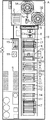
請求項1〜請求項3に記載の発明が含まれた実施の形態のグラビア印刷用被製版ロールのメッキ工場を図1を参照して説明する。
特に、この実施の形態のグラビア印刷用被製版ロールのメッキ工場は、ロボット室Aに、被製版ロールRを両端チャックしてハンドリングできるロボットハンド1aを有する往復旋回自在な産業用ロボット1を備え、該産業用ロボット1のハンドリングエリア内に、ロール入出装置2と二基のターンテーブル式のロールストック装置3A、3Bが設備されており、又、ロボット室Aに隣接するメッキ室Bには、天井に設備されたスタッカクレーン4の走行ラインの下側に中継台装置5と研磨装置6と写真廃液塗布装置7と脱脂(乾燥を含む)装置8とニッケルメッキ装置9と二基の硫酸銅メッキ装置10と二基のクロムメッキ装置11と二基の亜鉛メッキ装置12とペーパー研磨装置13とクロムメッキ溶解除去装置14とカセット組み込み台装置27が設備されている。
アウトラインとして、落版のための精密円筒加工ができるNC旋盤15と、ロール計測装置16が備えられている。ロールストック装置3A、3Bは、24本〜36本の被製版ロールを二段にストックできる大きさに構成できる。
メッキ室における被製版ロールRの搬送手段は、スタッカクレーン4と、例えば特開昭55−164095公報に示すように、被製版ロールRを両端チャックかつチャックコーンの外側を密封できてさらに各装置に載置されたときに回転できて必要に応じてチャックコーンを介してメッキ電流を流すことができる対向一対のチャック手段を備えたカセット形ロールチャック回転搬送ユニット17の共同作用により行われる。スタッカクレーン4とカセット形ロールチャック回転搬送ユニット17に換えて、被製版ロールRを両端チャックしてハンドリングできるロボットハンド1aを有する往復旋回自在な走行形の産業用ロボットを備えかつ各装置7〜14に被製版ロールを両端チャックして回転できて必要に応じてチャックコーンを介してメッキ電流を流すことができる対向一対のチャック手段を設けた設備としても良い。中継台装置5と研磨装置6は産業用ロボット1のハンドリングエリア内に設備されている必要があるので、ロボット室Aに寄って設置されているが、中継台装置5と研磨装置6の並び順は逆であっても良い。さらに、研磨装置6は、三基設備しているターンテーブル式のロールストック装置を一基減らすことで、ロボット室Aに設置しても良い。装置7〜14は、いずれの順に並べてもよい。
【0009】
図1に示す設備構成は、クライアントの多様な注文に応じた各種のメッキ工程が必要な製版会社にとって一ラインで全ての注文に対応できる好ましいライン設備を示している。すなわち、以下の多様なメッキ処理がなし得る。ライン全体の制御装置は、ディスプレイから以下の処理を選択できる。
(1)直版タイプのリユースロールであって、アウトラインでNC旋盤で精密円筒加工して落版してロール母材(鉄)が露出してしまった被製版ロールについては、脱脂処理してニッケルメッキ(下地メッキ)を付けてから硫酸銅メッキを付け、砥石研磨装置で精密円筒加工を行って取り出すことができる。この処理工程は、図2のフローチャートに示す。
(2)直版タイプのリユースロールであって、アウトラインでNC旋盤で精密円筒加工して落版してロール母材(鉄又はアルミニウム)が露出していない被製版ロールについては、脱脂処理して硫酸銅メッキを付け、砥石研磨装置で精密円筒加工を行って取り出すことができる。この処理工程も、図2のフローチャートに示す。
(3)NC旋盤とロール計測装置をアウトラインで備えていない場合には、直版タイプのリユースロールについて、アウトラインでNC旋盤による精密円筒加工して落版すること不可であるから、砥石研磨により落版・補正研磨し脱脂処理して硫酸銅メッキを付け付け、砥石研磨装置で精密円筒加工を行って取り出すことができる。この処理工程は、図3のフローチャートに示す。
(4)バラードメッキタイプのリユースの被製版ロールであってクライアントの要求により直版タイプのロールの扱いとすることができない場合には、脱脂処理してからロール表面性状を写真廃液を塗布して易剥離性とし、次ぎに硫酸銅メッキ(バラードメッキ)を厚く付けることができる。この処理工程は、図4のフローチャートに示す。
(5)硫酸銅メッキの上に亜鉛メッキが例えば30ミクロンの厚さとなるように付けられ電子彫刻装置又は炭酸ガスレーザ等の高出力レーザにより彫刻されその後クロムメッキを付けられてなるリユースロールであって、アウトラインでNC旋盤で精密円筒加工して落版して硫酸銅メッキが露出してなる被製版ロールについては、脱脂処理してから硫酸銅メッキし次いで亜鉛メッキを例えば35ミクロンの厚さとなるように付けて砥石研磨装置で5ミクロン削る精密円筒加工を行って取り出すことができる。この処理工程は、図5のフローチャートに示す。
(6)版(セル)を形成した被製版ロールについては、脱脂処理してクロムメッキを付け、ペーパー研磨により砂目を付けることができる。この処理工程は、図6のフローチャートに示す。
(7)印刷枚数が多くてクロムメッキを付け直したいときは、クロムメッキ溶解除去装置で溶解してから脱脂処理してクロムメッキを付けることができる。この処理工程は、図6のフローチャートに準じる。ただし、(5)の亜鉛メッキロールについては、クロムメッキの溶解と亜鉛メッキの溶解が同時進行するので適用できない。
(8)ロール母材がアルミニウムでありNC旋盤加工でアルミニウムが露出してしまった場合には上記の設備では硫酸銅メッキを付けられないが、ジンケート法によるニッケルメッキが行える前処理設備、又は、アノダール法によるピロ燐酸銅メッキが行える前処理設備をメッキラインに追加すれば適用できる。
【0010】
特に、図1に示すメッキ工場の発明としての特徴は、産業用ロボット1が走行形ではなく、往復旋回形であるという点、産業用ロボット1のハンドリングエリアに、三基のターンテーブル式のロールストック装置3A、3B、3Cと、中継台装置5と研磨装置6が設備されていることであり、その根拠は、以下の点にある。
往復旋回形の産業用ロボット1は、走行形産業用ロボットよりも価格及び設置スペースがそれぞれ約三分の一に抑えられ、そして、ロールを装置から装置に受け渡すタクトを走行形産業用ロボットのタクトよりも大幅に短縮できて稼動効率が上がる利点がある。反面、往復旋回形の産業用ロボットは、ハンドリングエリアが小さいので、ハンドリングエリア内にロールをストックできる本数が少なくなる。そこで、三基のターンテーブル式のロールストック装置3A、3B、3Cが設置されている。一基のターンテーブル式のロールストック装置3Aには、直径200mm×長さ1200mmの標準の大きさの被製版ロールを二段ストック構造のもので例えば20本から40本位ストックできる。
産業用ロボット1と、三基のターンテーブル式のロールストック装置3A、3B、3Cが設備されていなくても、アウトラインに設備されたNC旋盤で精密円筒加工され落版された被製版ロールを、人手により被製版ロールを持ち上げるか又はマニピュレータで被製版ロールを持ち上げて、中継台装置5の上に載置して、制御用コンピュータ(図示しない)においてメッキ処理のメニューを選択すれば、所望のメッキが行われ仕上げ研磨が行われる。しかし、これでは、一本のロールを投入毎に作業者が立ち会わなければならず、特に、夜間に無人で多数本のロールのメッキ処理が行えない。
これに対して、産業用ロボット1と、三基のターンテーブル式のロールストック装置3A、3B、3Cが設備されていると、一基のターンテーブル式のロールストック装置3Aに対して人手により被製版ロールを次々にストックしかつその都度に制御用コンピュータ(図示しない)においてメッキ処理のメニューを選択することができ、そして、ロールストック装置3Aから他の二基のロールストック装置3B,3Cへの移し変えを産業用ロボット1が倉庫管理に準じて行うこと、そして、三基のターンテーブル式のロールストック装置3A、3B、3Cのいずれかにストックされている被製版ロールを産業用ロボット1が中継台装置5の上に載置すること、そして、メッキして仕上げ研磨され中継台装置5の上に載置された被製版ロールを産業用ロボット1が三基のロールストック装置3A、3B、3Cのいずれかに戻すこと、そして、メッキして仕上げ研磨した被製版ロールについてロールストック装置3B,3Cからロールストック装置3Aへの移し変えを産業用ロボット1が行うことの全てを倉庫管理に準じて行うことができ、ロールストック装置3Aにストックされたメッキして仕上げ研磨した被製版ロールについては人手により容易に取り出すことができる。
従って、ロールストック装置3A、3B、3Cにストックできる本数だけ夜間に無人で全自動でメッキ処理・仕上げ研磨が行える。
二基のターンテーブル式のロールストック装置3A、3Bを設備し、研磨装置6をメッキラインから外してロールストック装置3Cを除いた位置に設置することができ、この場合は、メッキラインが短くなるとともに夜間に処理できるロールの本数が少なくなるが、安い設備コストを切望するクライアントに応じられる。ターンテーブル式のロールストック装置3Aを一基のみ設備する場合にはスペースが余るので2倍近い本数をストックできる構成にできる。
ロールストック装置3Aを一基のみ設備する場合にはスペースが余るので、研磨装置6とNC旋盤15をロールストック装置3B、3Cを除いた位置に設置することができ、NC旋盤15をインライン設備とすることができる。しかし、NC旋盤15は、アウトラインとして設備すれば、落版研磨によりロール母材が露出してしまったかどうかを肉眼で確認できて、被製版ロールをロールストック装置3Aにストックして制御用コンピュータ(図示しない)においてメッキ処理のメニューを選択する際に、所望のメッキが行われ仕上げ研磨が行われるシステムとすることがメッキ処理においてエラーを回避できる。
【0011】
続いて、図1中の各装置について簡略に説明する。
産業用ロボット1は、被製版ロールRの両端のチャック孔を避けて端面をチャックして自由な方向にハンドリングできるロボットハンド1aを有し、被製版ロールRをチャックして360度往復旋回できる。ロボットハンド1aは被製版ロールRの両端付近をチャックできれば良い。
【0012】
ロール入出装置2は、図7に示すように、特開平10-291289に示す装置に準ずる構成である。具体的には、エアシリンダ装置2aにより垂直面内に往復揺動される揺動フレーム2bを備え、揺動フレーム2bの上面部に、皿板の上面にゴムカバーが貼られてなるロールパレット2cを複数並べて固定載置し、各ロールパレット2cの端部より傾斜して立ち上がるロール受承板2dを設け、エアシリンダ2aにより揺動フレーム2bを揺動したときにロール受承板2dが床に近接しかつロールパレット2cに載置される被製版ロールRが立ち上がり傾斜状態になる構成である。
全自動無人製版ラインにより夜間に製版処理してストック台にストックして置いた被製版ロールを翌朝に一度に複数本取り出すことができることにより多数本の被製版ロールを短時間に取り出すことができる。特開平10-291289に示す装置のように、二重扉装置の間に設けるか、否かはクライアントの要望に応じてどちらにも対応できる。
【0013】
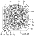
ターンテーブル式のロールストック装置3A、3Bは、図8、図9に示すように、円錐面の母線に被製版ロールRの面長方向が一致するように多数本の被製版ロールRをストック用ロールパレットに斜めに円周配列に二段に立て掛けることができかつストック用ロールパレットに対して被製版ロールのストック又は取り出しのために任意のストック用ロールパレットを所定に位置で停止し得る構造である。
詳述すると、図8に示すように、基盤3aに対してターンテーブル3bが回転可能に設けられ、基盤3aに設けられたサーボモータ3cの回転が減速機3d、スプロケット3e,3fを介してターンテーブル3bに巻き付けられ固定されたエンドレスチェーン3gに伝達されてターンテーブル3bが回転するようになっている。さらに、ターンテーブル3bの周縁部の四箇所の下面がローラー3mで受けられ、該ローラー3mがロールの荷重を担持しているとともに、ターンテーブル3bの周縁部の所要の一箇所が基盤3aに設けられたインデックス係止装置(図示しない)により位置決め固定されるようになっている。
そして、図9に示すように、ターンテーブル3bの上に下段のストック用ロールパレット3hと上段のストック用ロールパレット3iが設けられている。ストック用ロールパレット3h、3iは、一本の任意の長さかつ任意の外径の被製版ロールを斜めに立て掛けるときの該被製版ロールの下端の傾斜側の左右二点を同じ位置において受承する二つの平面を有する下側受承部材3h'、3i'と、該被製版ロールの上端の傾斜側の左右二点を同じ位置において受承する二つの平面を有する上側受承部材3h”、3i”とからなり、下側受承部材3h'、3i'の下端には、被製版ロールRの下端が下側受承部材3h'、3i'のロール受承面から滑り離れることがないように被製版ロールRの下端面を受承するロール下端面受承板3jが張り出して設けられている。下側受承部材3h'は、ターンテーブル3bの上面に固定され、又、下側受承部材3i'と上側受承部材3h”,3i”はターンテーブル3bの上に設けられるフレーム3j支持される。
特に、被製版ロールの上端を係止する上側受承部材3h”、3i”は水平断面が鈍角で縦長の二面体であり、被製版ロールの長さが短くなると傾斜が大きくなって重心とロール下端(支点)との水平方向の距離が大きく変化してターンテーブル3bの回転時に被製版ロールに遠心力が加わっても垂直に起き上がってさらに外側へ転倒することがないように構成されている。
ターンテーブル3bの周縁部のストック用ロールパレットに対応する各位置にアドレスを検出できるように所要数のビットを有するアドレスプレート3nが取付けられ、各アドレスプレートのビットを固定側の所要位置に付設されたセンサ3pが読み取り、コントローラ(図示しない)がセンサが読み取ったアドレスを判別してサーボモータ3cを制御し任意のストック用ロールパレットを所定に位置で停止し得る。
従って、ストック用ロールパレットに対して被製版ロールのストック又は取り出しのために下段又は上段の任意のストック用ロールパレットを所定に位置で停止し得る。
【0014】
スタッカクレーン4はカセット形ロールチャック回転搬送ユニット17を吊り上げて搬送し得る構成である。カセット型ロールチャック装置17は、一対のチャックコーンにより被製版ロールRの両端のチャック孔をチャックし、一対の防水キャップによりチャックコーンの外側を隠蔽して被製版ロールRの両端のチャック孔を防水し、装置フレームの両側の端板が処理装置に載置されたときに駆動側のチャックコーンが処理装置に供えている回転駆動源と接続され被製版ロールRを回転しうるようになっている。カセット形ロールチャック回転搬送ユニット17は、装置フレームの端板がメッキ装置9,10,11,12に載置されたときには一対のチャックコーンの基部が通電ブラシの上に載置されメッキ電流が通電されるようになっている。(特開昭55-164095公報に示す)
【0015】
産業用ロボット1は、被製版ロールRをチャックして中継台装置5の四本の円錐ロールの上に受け渡し、又、四本の円錐ロールの上に載置された被製版ロールRを受け取る。スタッカクレーン4は、カセット形ロールチャック回転搬送ユニット17を吊り上げて中継台装置5の四本の円錐ロールの上に載せられた被製版ロールRの上にセットする。すると、カセット形ロールチャック回転搬送ユニット17が被製版ロールRが両端チャックし、スタッカクレーン4は、カセット形ロールチャック回転搬送ユニット17を吊り上げて装置7〜14間を搬送する。装置5、7〜14は、カセット形ロールチャック回転搬送ユニット17の装置フレームの両側の端板を湾部に受け入れて該カセット形ロールチャック回転搬送ユニット17を載置した状態となり、この状態で被製版ロールRに対して着脱、洗浄・乾燥、脱脂処理、硫酸銅メッキ処理、クロムメッキ処理、亜鉛メッキ処理、ペーパー研磨処理、又はクロムメッキ溶解除去処理ができる構成である。
【0016】
研磨装置6は、落版用の粗仕上げ砥石と中仕上げ砥石と上仕上げ砥石と鏡面研磨用砥石の四ヘッド研磨装置の採用が好ましい。研磨装置6は、産業用ロボット1との間で被製版ロールRの授受を行う。
【0017】
NC旋盤15は、図10及び図11に示すように、コンピュータディスプレイから所要寸法を入力すると、複式刃物台に設けられている測定用のプローブが、水平に両端チャックした被製版ロールRに対して自動的に多点計測して削り代を決定して精密円筒加工を行なうようになっている。NC旋盤加工終了時の直径値とクロムメッキ前の仕上げ寸法として要求する直径値との差の半分に精密円筒研磨される研磨代を加えた値が、NC旋盤加工後に版深を確保するメッキの厚みとなるように精密円筒加工を行なう。
【0018】
ロール計測装置16は、被製版ロールの全長、外径、孔径、ロールの一端から他端まで一定ピッチ毎に直径を計測する直径計測を行なう。NC旋盤15がロール計測を有しているときは、ロール計測装置16は不要である。
【0019】
請求項1〜請求項3に記載の発明が含まれた実施の形態のグラビア印刷用被製版ロールのメッキ工場を図12を参照して説明する。
特に、この実施の形態のグラビア印刷用被製版ロールのメッキ工場は、ロボット室Aに、被製版ロールRを両端チャックしてハンドリングできるロボットハンド1aを有する往復旋回自在な産業用ロボット1を備え、該産業用ロボット1のハンドリングエリア内に、ロール入出装置2とロールストック装置3Dが設備されており、又、ロボット室Aに隣接するメッキ室Bには、天井に設備されたスタッカクレーン4の走行ラインの下側に中継台装置5と研磨装置6と写真廃液塗布装置7と脱脂(乾燥を含む)装置8とニッケルメッキ装置9と二基の硫酸銅メッキ装置10と二基のクロムメッキ装置11と二基の亜鉛メッキ装置12とペーパー研磨装置13とクロムメッキ溶解除去装置14とカセット組み込み台装置27が設備されている。特に、この実施の形態は、図1に示すロールストック装置3A、3Bに替えてロールストック装置3Dを設備した点が相違する。すなわち、ターンテーブル式に限定されるものではないことを示している。
発明としての要点は、産業用ロボット1のハンドリングエリア内に、ストック用ロールパレットを多数有し該ストック用ロールパレットにストックする被製版ロールを産業用ロボットとの間で授受するロールストック装置3Dと、ロール入出装置2と、中継台装置5と、砥石研磨装置6を備えて、産業用ロボット1が被製版ロールRの受け渡しを行えること、中継台装置5と、砥石研磨装置6はメッキラインに設備されていることにより、産業用ロボット1が往復旋回形であるのに多数の装置との間で被製版ロールの受け渡しができてかつメッキラインとの被製版ロールの受け渡しができる構成である。ロールストック装置3Dは、20本〜30本位の被製版ロールを立て掛けてかつ扇状配置に一段にストックできる大きさに構成できる。
【0020】
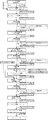
続いて、請求項4、請求項7及び請求項8に記載の発明が含まれた実施の形態のグラビア製版工場を図13を参照して説明する。
この実施の形態のグラビア製版工場は、ロボット室Aに、被製版ロールRを両端チャックしてハンドリングできるロボットハンド1aを有する往復旋回自在な産業用ロボット1を備え、該産業用ロボット1のハンドリングエリア内に、ロール入出装置2とターンテーブル式のロールストック装置3Aが設備されているとともに、ポジ型又はネガ型の感光膜を塗布する感光膜塗布装置18とレーザ露光装置19が二段積みに設備されており、又、ロボット室Aに隣接するメッキ室Bには、天井に設備されたスタッカクレーン4の走行ラインの下側に中継台装置5と研磨装置6と写真廃液塗布装置7と脱脂(乾燥を含む)装置8と現像装置20と腐食装置21とレジスト剥離装置22とニッケルメッキ装置9と二基の硫酸銅メッキ装置10と二基のクロムメッキ装置11とペーパー研磨装置13とクロムメッキ溶解除去装置14とカセット組み込み台装置27が設備されている。
さらに、アウトラインとして、落版のための精密円筒加工ができるNC旋盤15と、ロール計測装置16と校正刷り印刷機23が備えられている。ロールストック装置3Aは、24本〜36本の被製版ロールを二段にストックできる大きさに構成できる。なお、感光膜塗布装置18とレーザ露光装置19を二段積みとはせずに別々に設置し、各装置18,19の上に、一段ストック構造のロールストック装置を設置しても良い。
メッキ室Bにおける被製版ロールRの搬送手段は、スタッカクレーン4と、カセット形ロールチャック回転搬送ユニット17の共同作用により行われる。三基設備しているターンテーブル式のロールストック装置を一基減らすことで、研磨装置6又はNC旋盤15をロボット室Aに設置しても良い。装置7〜14は、いずれの順に並べてもよい。
【0021】
図14は、感光膜塗布装置18を示す。この感光膜塗布装置18は、塗布膜の形成を行なう被製版ロールRを両端チャックして回転するロールチャック回転手段18aと、被製版ロールRに沿って移動する移動台18bと、移動台18bに設けられた昇降テーブル18cに可動ブラケットを介して設けられた拭浄ヘッド18dと昇降テーブル18cに設けられている塗布ヘッド18eを備えてなり、拭浄ヘッド18dと塗布ヘッド18eが被製版ロールRの軸心方向に並び、移動台18bが被製版ロールRの一端に対応する位置から他端に対応する位置まで移動して、拭浄ヘッド18cが回転する被製版ロールRの一端から他端まで拭浄を行ない、塗布ヘッド18eが拭浄ヘッド18dの後を追って感光膜塗布を行ない、感光膜が乾燥するまで被製版ロールRの回転を続行する構成である。塗布ヘッド18eはワイピングクロムTを繰り出して被製版ロールRを拭浄する。塗布ヘッド18eは、必要な塗布に必要な量よりも僅かに多くなるようにパイプの上端から湧き出すようにして被製版ロールにパイプが非接触に近接して感光膜を塗布する。
【0022】
図13に示す設備構成は、クライアントの多様な注文に応じた各種のメッキ工程が必要な製版会社にとって一ラインで全ての注文に対応できる好ましいライン設備を示している。すなわち、以下の多様なグラビア製版がなし得る。ライン全体の制御装置は、ディスプレイから以下の処理を選択できる。
(1)直版タイプのリユースロールであって、アウトラインでNC旋盤で精密円筒加工して落版してロール母材(鉄)が露出してしまった被製版ロールについては、脱脂処理してニッケルメッキ(下地メッキ)を付けてから硫酸銅メッキを付け、砥石研磨装置で精密円筒加工を行ってから、感光膜塗布し、レーザー露光により画像を焼き付け、現像し、腐食してセルを形成し、レジスト剥離し、クロムメッキを付け、ペーパー研磨により砂目を立てて取り出すことができる。この処理工程は、図15のフローチャートに示す。
(2)直版タイプのリユースロールであって、アウトラインでNC旋盤で精密円筒加工して落版してロール母材(鉄又はアルミニウム)が露出していない被製版ロールについては、脱脂処理して硫酸銅メッキを付け、砥石研磨装置で精密円筒加工を行ってから、感光膜を塗布形成し、レーザー露光により画像を焼き付け、現像し、腐食してセルを形成し、レジスト剥離し、クロムメッキを付け、ペーパー研磨により砂目を立てて取り出すことができる。この処理工程も、図15のフローチャートに示す。
(3)NC旋盤とロール計測装置をアウトラインで備えていない場合には、直版タイプのリユースロールについて、アウトラインでNC旋盤による精密円筒加工して落版すること不可であるから、砥石研磨により落版・補正研磨し脱脂処理してニッケルメッキ(下地メッキ)を付けてから硫酸銅メッキを付け、砥石研磨装置で精密円筒加工を行ってから、感光膜塗布し、レーザー露光により画像を焼き付け、現像し、腐食してセルを形成し、レジスト剥離し、クロムメッキを付け、ペーパー研磨により砂目を立てて取り出すことができる。フローチャートは示していない。
(4)バラードメッキタイプのリユースの被製版ロールであってクライアントの要求により直版タイプのロールの扱いとすることができない場合には、脱脂処理してからロール表面性状を写真廃液を塗布して易剥離性とし、次ぎに硫酸銅メッキ(バラードメッキ)を厚く付け、砥石研磨装置で精密円筒加工を行ってから、感光膜塗布し、レーザー露光により画像を焼き付け、現像し、腐食してセルを形成し、レジスト剥離し、クロムメッキを付け、ペーパー研磨により砂目を付けて取り出すことができる。フローチャートは示していない。
【0023】
続いて、請求項5、請求項7及び請求項8に記載の発明が含まれた実施の形態のグラビア製版工場を図16を参照して説明する。
特に、この実施の形態のグラビア製版工場は、ロボット室Aに、被製版ロールRを両端チャックしてハンドリングできるロボットハンド1aを有する往復旋回自在な産業用ロボット1を備え、該産業用ロボット1のハンドリングエリア内に、ロール入出装置2とターンテーブル式のロールストック装置3Aが設備されているとともに、レーザーアブレーション膜を塗布するレーザーアブレーション膜塗布装置24と、レーザーアブレーション用のレーザ露光装置25が備えられているとともに、装置24、25の上にターンテーブル式のロールストック装置3E、3Fが備えられており、又、ロボット室Aに隣接するメッキ室Bには、天井に設備されたスタッカクレーン4の走行ラインの下側に中継台装置5と研磨装置6と写真廃液塗布装置7と脱脂装置8と腐食装置21とレジスト剥離装置22とニッケルメッキ装置9と二基の硫酸銅メッキ装置10と二基のクロムメッキ装置11とペーパー研磨装置13とクロムメッキ溶解除去装置14とが設備されている。なお、レーザーアブレーション膜塗布装置24とレーザ露光装置25を二段積みとして、二段ストック構造のロールストック装置を設置しても良い。
アウトラインとして、落版のための精密円筒加工ができるNC旋盤15と、ロール計測装置16、校正刷り印刷機23が備えられる。ロールストック装置3E、3Fは、25本〜35本の被製版ロールを一段にストックできる大きさに構成できる。
メッキ室における被製版ロールRの搬送手段は、スタッカクレーン4と、カセット形ロールチャック回転搬送ユニット17の共同作用により行われる。三基設備しているターンテーブル式のロールストック装置を一基減らすことで、研磨装置6又はNC旋盤15をロボット室Aに設置しても良い。装置7〜14は、いずれの順に並べてもよい。
【0024】
図16に示す設備構成は、クライアントの多様な注文に応じた各種のメッキ工程が必要な製版会社にとって一ラインで全ての注文に対応できる好ましいライン設備を示している。すなわち、以下の多様なグラビア製版がなし得る。ライン全体の制御装置は、ディスプレイから以下の処理を選択できる。
(1)直版タイプのリユースロールであって、アウトラインでNC旋盤で精密円筒加工して落版してロール母材(鉄)が露出してしまった被製版ロールについては、脱脂処理してニッケルメッキ(下地メッキ)を付けてから硫酸銅メッキを付け、砥石研磨装置で精密円筒加工を行ってから、レーザーアブレーション膜を塗布形成し、レーザーアブレーションを行いネガ画像を形成し、腐食してセルを形成し、レジスト剥離し、クロムメッキを付け、ペーパー研磨により砂目を立てて取り出すことができる。この処理工程は、図17のフローチャートに示す。
(2)直版タイプのリユースロールであって、アウトラインでNC旋盤で精密円筒加工して落版してロール母材(鉄又はアルミニウム)が露出していない被製版ロールについては、脱脂処理して硫酸銅メッキを付け、砥石研磨装置で精密円筒加工を行ってから、感光膜塗布し、レーザーアブレーション膜を塗布形成し、レーザーアブレーションを行いネガ画像を形成し、腐食してセルを形成し、レジスト剥離し、クロムメッキを付け、ペーパー研磨により砂目を立てて取り出すことができる。この処理工程も、図17のフローチャートに示す。
(3)NC旋盤とロール計測装置をアウトラインで備えていない場合には、直版タイプのリユースロールについて、アウトラインでNC旋盤による精密円筒加工して落版すること不可であるから、砥石研磨により落版・補正研磨し脱脂処理してニッケルメッキ(下地メッキ)を付けてから硫酸銅メッキを付け、砥石研磨装置で精密円筒加工を行ってから、レーザーアブレーション膜を塗布形成し、レーザーアブレーションを行いネガ画像を形成し、腐食してセルを形成し、レジスト剥離し、クロムメッキを付け、ペーパー研磨により砂目を付けて取り出すことができる。
(4)バラードメッキタイプのリユースの被製版ロールであってクライアントの要求により直版タイプのロールの扱いとすることができない場合には、脱脂処理してからロール表面性状を写真廃液を塗布して易剥離性とし、次ぎに硫酸銅メッキ(バラードメッキ)を厚く付け、砥石研磨装置で精密円筒加工を行ってから、レーザーアブレーション膜を塗布形成し、レーザーアブレーションを行いネガ画像を形成し、腐食してセルを形成し、レジスト剥離し、クロムメッキを付け、ペーパー研磨により砂目を付けて取り出すことができる。
【0025】
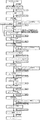
続いて、請求項6、請求項7及び請求項8に記載の発明が含まれた実施の形態のグラビア製版工場を図18を参照して説明する。
特に、この実施の形態のグラビア製版工場は、ロボット室Aに、被製版ロールRを両端チャックしてハンドリングできるロボットハンド1aを有する往復旋回自在な産業用ロボット1を備え、該産業用ロボット1のハンドリングエリア内に、ロール入出装置2とターンテーブル式のロールストック装置3Aが設備されているとともに、符号26で示す電子彫刻装置又は高出力のレーザー彫刻装置が設備されており、又、ロボット室Aに隣接するメッキ室Bには、天井に設備されたスタッカクレーン4の走行ラインの下側に中継台装置5と研磨装置6と写真廃液塗布装置7と脱脂装置8とニッケルメッキ装置9と二基の硫酸銅メッキ装置10とクロムメッキ装置11と亜鉛メッキ装置12とペーパー研磨装置13とクロムメッキ溶解除去装置14とカセット組み込み台装置27が設備されている。なお、電子彫刻装置又は高出力のレーザー彫刻装置26の上にも一段ストック構造のロールストック装置を設置しても良い。
アウトラインとして、落版のための精密円筒加工ができるNC旋盤15と、ロール計測装置16が備えられる。
メッキ室における被製版ロールRの搬送手段は、スタッカクレーン4と、カセット形ロールチャック回転搬送ユニット17の共同作用により行われる。三基設備しているターンテーブル式のロールストック装置を一基減らすことで、研磨装置6又はNC旋盤15をロボット室Aに設置しても良い。装置7〜14は、いずれの順に並べてもよい。
【0026】
図18に示す設備構成は、クライアントの多様な注文に応じた各種のメッキ工程が必要な製版会社にとって一ラインで全ての注文に対応できる好ましいライン設備を示している。すなわち、以下の多様なグラビア製版がなし得る。ライン全体の制御装置は、ディスプレイから以下の処理を選択できる。
(1)直版タイプのリユースロールであって、アウトラインでNC旋盤で精密円筒加工して落版してロール母材(鉄)が露出してしまった被製版ロールについては、脱脂処理してニッケルメッキ(下地メッキ)を付けてから硫酸銅メッキを付け、砥石研磨装置で精密円筒加工を行ってから、符号26で示す電子彫刻装置によりセルを形成し、脱脂処理して、クロムメッキを付け、ペーパー研磨により砂目を付けて取り出すことができる。この処理工程は、図19のフローチャートに示す。
(2)直版タイプのリユースロールであって、アウトラインでNC旋盤で精密円筒加工して落版してロール母材(鉄又はアルミニウム)が露出していない被製版ロールについては、脱脂処理して硫酸銅メッキを付け、砥石研磨装置で精密円筒加工を行ってから、符号26で示す電子彫刻装置によりセルを形成し、脱脂処理して、クロムメッキを付け、ペーパー研磨により砂目を付けて取り出すことができる。この処理工程も、図19のフローチャートに示す。
(3)NC旋盤とロール計測装置をアウトラインで備えていない場合には、直版タイプのリユースロールについて、アウトラインでNC旋盤による精密円筒加工して落版すること不可であるから、砥石研磨により落版・補正研磨し脱脂処理してニッケルメッキ(下地メッキ)を付けてから硫酸銅メッキを付け、砥石研磨装置で精密円筒加工を行ってから、符号26で示す電子彫刻装置によりセルを形成し、脱脂処理して、クロムメッキを付け、ペーパー研磨により砂目を付けて取り出すことができる。
(4)バラードメッキタイプのリユースの被製版ロールであってクライアントの要求により直版タイプのロールの扱いとすることができない場合には、脱脂処理してからロール表面性状を写真廃液を塗布して易剥離性とし、次ぎに硫酸銅メッキ(バラードメッキ)を厚く付け、砥石研磨装置で精密円筒加工を行ってから、符号26で示す電子彫刻装置によりセルを形成し、脱脂処理して、クロムメッキを付け、ペーパー研磨により砂目を付けて取り出すことができる。
(5)硫酸銅メッキの上に亜鉛メッキが例えば30ミクロンの厚さとなるように付けられ電子彫刻装置又は炭酸ガスレーザ等の高出力レーザにより彫刻されその後クロムメッキを付けられてなるリユースロールであって、アウトラインでNC旋盤で精密円筒加工して落版してなる被製版ロールについては、脱脂処理してから硫酸銅メッキして精密円筒研磨した亜鉛メッキを例えば35ミクロンの厚さとなるように付けて砥石研磨装置で5ミクロン削る精密円筒加工を行ってから、符号26で示す電子彫刻装置又は高出力のレーザー彫刻装置によりセルを形成し、脱脂処理して、クロムメッキを付け、ペーパー研磨により砂目を付けて取り出すことができる。
【0027】
【発明の効果】
以上説明してきたように、本願発明のグラビア印刷用被製版ロールのメッキ工場は、往復旋回形の産業用ロボットのハンドリングエリア内に、ロール入出装置と、多数本の被製版ロールをストックできるロールストック装置と、中継台装置と、砥石研磨装置を備え、特に、中継台装置と砥石研磨装置をメッキラインに設備したことにより、これら装置が産業用ロボットのハンドリングエリア内に収まり、これら装置との間で産業用ロボットが被製版ロールの受け渡しを行える構成であること、そして、ロールストック装置は、20本〜30本位、あるいは60本〜70本位の被製版ロールをストックできる大きさに構成でき、
又、本願発明のグラビア製版工場は、往復旋回形の産業用ロボットのハンドリングエリア内に、ロール入出装置と、多数本の被製版ロールをストックできるロールストック装置と、中継台装置と、砥石研磨装置を備え、特に、中継台装置と砥石研磨装置をメッキラインに設備したことと、及び膜塗布装置とレーザー露光装置とロールストック装置を任意の二段積みとしたことにより、これら装置が産業用ロボットのハンドリングエリア内に収まり、これら装置との間で産業用ロボットが被製版ロールの受け渡しを行える構成であること、そして、ロールストック装置は、20本〜30本位、或いは60本〜70本位の被製版ロールをストックできる大きさに構成できるから、以下の効果を有する。
(1)昼間の作業者が居るときの全自動稼動は勿論のこと、夕方に作業者全員が帰宅し工場内が無人になる前に夜間に処理すべき被製版ロールの全本数をストックして、その際にそれぞれに異なるメッキ工程、メッキ-製版工程を制御装置に入力しておくと、夜間に無人で全自動でメッキラインへの被製版ロールの投入を一本ずつ順番に行って、多数本の被製版ロールをついてそれぞれに異なるメッキ工程、メッキ-製版工程で処理を実行して、メッキ済み又は製版済みのロールを全本数ストックしておくことができ、翌朝には全本数のロールを取り出すことができて稼働率が非常に高い、グラビア印刷用被製版ロールのメッキ工場及びグラビア製版工場を提供できる。
(2)旋回形産業用ロボットを採用することにより、設備コストの大幅な低減と小スペース化と装置全体の高い稼動効率が達成できる、グラビア印刷用被製版ロールのメッキ工場及びグラビア製版工場を提供できる。
(3)大きさがさまざまに異なる多数本の被製版ロールを極めて小スペースにストックしておくことができ回転しても外方へ転倒する惧れがないターンテーブル式のロールストック装置及び旋回形産業用ロボットを採用することにより、小スペース化が達成でき、ストック装置を複数基設置した場合にも産業用ロボットによりストック装置間のロールの移し変え移送を容易に行うことができ、ストック装置のどの位置にストックしたロールでも産業用ロボットが迅速に取り出してメッキラインへの投入位置へ移送することができ、産業用ロボットが関与するあらゆるロールの移送タクト、具体的には、メッキ済みのロール、製版途中のロール及び製版済みのロールをストック装置又はロボットの周辺の装置に移送する移送タクトを短縮できて装置全体の稼動効率が高めることができる、グラビア印刷用被製版ロールのメッキ工場及びグラビア製版工場を提供できる。
(4)アウトラインで旋盤による落版円筒加工した被製版ロールを対象にすると、ロールストック時にそれぞれに異なるメッキ工程、メッキ-製版工程を制御装置に入力しておくことができ、処理が完了したロールにメッキが良好に付いていなくて、製品にならないロールの輩出を回避でき、特に夜間に多数本の被製版ロールを無人で全自動で高い信頼性を有して処理ができる、グラビア印刷用被製版ロールのメッキ工場及びグラビア製版工場を提供できる。
【図面の簡単な説明】
【図1】請求項1、請求項2及び請求項8に記載の発明が含まれた実施の形態のグラビア印刷用被製版ロールのメッキ工場の概略平面図。
【図2】図1に示すメッキ工場で実施できるメッキ工程のフローチャート。
【図3】図1に示すメッキ工場で実施できる別のメッキ工程のフローチャート。
【図4】図1に示すメッキ工場で実施できる別のメッキ工程のフローチャート。
【図5】図1に示すメッキ工場で実施できる別のメッキ工程のフローチャート。
【図6】図1に示すメッキ工場で実施できる別のメッキ工程のフローチャート。
【図7】図1に示すメッキ工場の要部のロール入出装置の概略縦断面図。
【図8】図1に示すメッキ工場の要部のロールストック装置の概略平面図。
【図9】図1に示すメッキ工場の要部のロールストック装置の概略縦断面図。
【図10】NC旋盤の精密円筒加工を行なうための入力値や計測値及び削り代等の計算値を表すディスプレイ表示画面。
【図11】NC旋盤の精密円筒加工を行なうための入力値や計測値及び削り代等の計算値の関係をロール断面に表した図。
【図12】請求項1、請求項2及び請求項3に記載の発明が含まれた他の実施の形態のグラビア印刷用被製版ロールのメッキ工場の概略平面図。
【図13】請求項4、請求項7及び請求項8に記載の発明が含まれた実施の形態のグラビア製版工場の概略平面図。
【図14】図13に示すグラビア製版工場に設備される感光膜塗布装置の概略正面図。
【図15】図13に示すグラビア製版工場で実施できるメッキ・製版工程のフローチャート。
【図16】請求項5、請求項7及び請求項8に記載の発明が含まれた実施の形態のグラビア製版工場の概略平面図。
【図17】図16に示すグラビア製版工場で実施できるメッキ・製版工程のフローチャート。
【図18】請求項6、請求項7及び請求項8に記載の発明が含まれた実施の形態のグラビア製版工場の概略平面図。
【図19】図18に示すグラビア製版工場で実施できるメッキ・製版工程のフローチャート。[0001]
BACKGROUND OF THE INVENTION
The present invention relates to a plating factory for a gravure printing roll and a gravure printing factory capable of forming a series of plating processes and cells on a gravure printing roll unattended and unattended at night.
[0002]
[Prior art]
Conventionally, the gravure plate making process of the direct plate type plate making roll is carried-in-chromium peeling-correction polishing / plate printing polishing-degreasing-water washing-acid washing-water washing-copper sulfate plating-grinding stone polishing-negative photosensitive film coating formation. -Image printing with a laser exposure device-Development-Etching-Resist peeling-Chrome plating-Paper polishing-Unloading process.
Or carry-in-chromium peeling-correction polishing / depressing plate polishing-degreasing-water washing-acid washing-water washing-copper sulfate plating-grinding stone polishing-ablation type photosensitive film coating formation-image printing (ablation) -etching by laser exposure apparatus- It is a process of resist peeling-chromium plating-paper polishing-carrying out.
Furthermore, it is a process of carrying-in-chromium peeling-correction polishing / plate printing polishing-degreasing-water washing-acid washing-water washing-copper sulfate plating-grinding stone polishing-engraving with an electronic engraving machine-chromium plating-paper polishing-unloading. .
[0003]
As technical literatures that disclose the gravure plate making process, Japanese Patent Application Nos. 10-193551, 10-193552, JP 2000-062342, JP 2000-062343, JP 2000-062344, JP 2001-179923 , JP 2001-179924, JP 2001-187440, JP 2001-187441, JP 2001-191475, JP 2001-191476, JP 2001-260304, JP 2002-127369, JP 2002-187249, JP 2002-187250, JP 2002-200728, JP 2002-200729, JP 2002-307640, and JP 2002-307641.
[0004]
[Problems to be solved by the invention]
In order to process a large number of plate-making rolls unattended at night and fully automatically, a large number of plate-making rolls need to be quickly put into the plating line. In addition, it is necessary to transfer the plate making roll after plating to the plate making apparatus with a short tact. On the other hand, since customers want to introduce cheap facilities, provision of compact devices is required.
At night, there are customers who wish to have at least about 30 unattended, fully automatic plating, and plating / engraving, and about 60 unattended, unattended, fully automatic, plating / engraving. There are customers who desire about 90, unattended, fully automatic plating processing, and further, plating / plate making processing. Building factory facilities that can handle all of these customers is an issue.
[0005]
On the other hand, if round processing using an NC lathe can be adopted instead of grinding wheel polishing in the plate-making process of the recycle plate making of direct type gravure printing rolls, the degree of distorting of the roll will be improved even if the roll is used many times. Unlike rounding with overhaul, the machining allowance can be kept small, so that rounding can be performed with an NC lathe to the extent that the roll base material is not exposed. Nickel plating after the treatment, and then copper sulfate plating, and for aluminum rolls, nickel plating in the plate making process where copper sulfate plating is applied after the zincate or anodal plating pretreatment is applied. This is desirable because it is not necessary to perform a pre-plating process of the zincate method or the anodal method.
Moreover, if round processing by NC lathe can be adopted instead of grinding wheel polishing in the plate making process of recycling plate making of straight type gravure printing roll, the conventional round processing of overhaul by NC lathe is unnecessary. Only rolls that are so distorted that they cannot be dealt with by round machining with an NC lathe can be turned overhaul or used as waste rolls, which is desirable because they can be adapted as recyclable rolls at an overwhelming rate.
[0006]
The present invention stocks the total number of plate rolls to be processed at night before all workers return home in the evening and the factory is unattended, as well as fully automatic operation when there are daytime workers. In this case, if different plating processes and plating-plate making processes are input to the control device at that time, the plate making rolls are put into the plating line one by one unattended at night. A large number of plate-making rolls can be processed in different plating processes and plating-plate-making processes, and all the plated or pre-rolled rolls can be stocked. It is an object of the present invention to provide a gravure printing plate plating factory and a gravure printing factory, which can take out the ink and have a very high operation rate.
The invention of the present application provides a gravure printing roll plate plating factory and a gravure printing factory that can achieve a significant reduction in equipment cost, a small space, and a high operating efficiency of the entire apparatus by adopting a swivel type industrial robot. It is intended to provide.
The present invention relates to a turntable roll stock apparatus and a swivel that can stock a large number of plate-making rolls of various sizes in a very small space and do not fall over even if rotated. By adopting an industrial robot, the space can be reduced, and even when multiple stock devices are installed, the industrial robot can easily transfer and transfer rolls between stock devices. Any roll stocked at any position can be quickly taken out by the industrial robot and transferred to the input position to the plating line. Any roll transfer tact involving the industrial robot, specifically, a plated roll Shortens the transfer tact for transferring the pre-rolling roll and the pre-rolled roll to the stock equipment or the equipment around the robot Can be increased is operating efficiency of the entire apparatus can, and its object is to provide a plating factory and gravure engraving plant of the plate-making roll for gravure printing.
The invention of this application is intended for plate making rolls that have been subjected to cylinder printing with a lathe in outline, so that different plating processes and plating-plate making processes can be input to the control device at the time of roll stock, and the processing is completed. For the gravure printing, which can avoid the production of rolls that do not become products because the plating is not well applied to the rolls, and can process a large number of plate-making rolls unattended and fully automatically and with high reliability, especially at night. The purpose is to provide a plate-making roll plating factory and a gravure plate-making factory.
[0007]
[Means for Solving the Problems]
ClaimThe invention described in 1 is provided with a robot hand that includes a plating line facility having at least a copper sulfate plating apparatus, and that is adjacent to one end in the line direction of the plating line facility and can be handled by chucking a plate-making roll at both ends. A reciprocating industrial robot having a large number of stock roll pallets in the handling area of the industrial robot.In any stacking systemstockIsA roll stock device for transferring the plate-making roll to and from an industrial robot, and having a single or a plurality of input / output roll pallets, the swingable input / output roll pallets in a horizontal state and a steep slope A roll loading / unloading device that is swingable in a state and is capable of entering and exiting the plate making roll obliquely leaning on the loading and unloading roll pallet and transferring the plate making roll with an industrial robot in a horizontal state;
Furthermore, the grindstone polishing apparatus is located in the handling area of the industrial robot and located at one end in the line direction of the plating line equipment,
An industrial robot is configured to deliver a plate-making roll between a roll loading / unloading device, a roll stock device, and a grindstone polishing device,
Further, as the plating line equipment, a relay stand device for relaying the delivery of the plate making roll between the industrial robot and the roll handling means of the plating line equipment is provided so as to be located in the handling area of the industrial robot. An object of the present invention is to provide a plating factory for a plate roll for gravure printing, which is characterized in that.
ClaimIn the invention described in No. 2, the roll stock apparatus has a plurality of plate-making rolls arranged on a stock roll pallet obliquely in a circumferential arrangement so that the surface length direction of the plate-making roll coincides with a conical surface bus. It is a turntable type roll stock device that can stand in two stages and can stop any stock roll pallet at a predetermined position for stocking or taking out the plate making roll from the stock roll pallet. An object of the present invention is to provide a plating factory for a gravure printing roll according to
ClaimThe invention described in No. 3 is characterized in that an NC lathe is provided with an outline that performs plate release by chucking both ends of a reusable straight plate-type pre-rolled roll and precision cylinder processing.Claim1 orClaimAn object of the present invention is to provide a plating factory for the plate-making roll for gravure printing described in 2.
Claim 4The invention described in (1) includes a plating line facility having at least a copper sulfate plating device, the plating line facility is provided with a developing device, an etching device, and a resist stripping device, and further adjacent to one end of the plating line facility in the line direction. And a reciprocating industrial robot having a robot hand that can be handled by chucking the plate-making roll at both ends, and having one or a plurality of input / output roll pallets in the handling area of the industrial robot. An in-and-out roll pallet that can be freely swung between a horizontal state and a steeply inclined state, and a plate-making roll can be placed on and out of the loading-and-unloading roll pallet at an angle, and the plate-making roll can be put in and out in a horizontal state. Photosensitive film coating apparatus for applying a positive type or negative type photosensitive film Laser exposure device, and has a number of stock rolls pallets to the stock roll palletIn any stacking systemstockIsEquipped with a roll stock device that sends and receives pre-made rolls with industrial robots in any stacking system,
Furthermore, the grindstone polishing apparatus is located in the handling area of the industrial robot and located at one end in the line direction of the plating line equipment,
An industrial robot is configured to deliver a plate-making roll between a roll loading / unloading device, a roll stock device, and a grindstone polishing device,
Further, as the plating line equipment, a relay stand device for relaying the delivery of the plate making roll between the industrial robot and the roll handling means of the plating line equipment is provided so as to be located in the handling area of the industrial robot. Become
An object of the present invention is to provide a gravure plate making factory characterized in that plate making is performed by copper sulfate plating-polishing-photosensitive film coating-laser image printing-development-etching processes.
Claim 5The invention described in includes a plating line facility having at least a copper sulfate plating device, the plating line facility includes an etching device and a resist stripping device, and further adjacent to one end in the line direction of the plating line facility, A reciprocating industrial robot having a robot hand that can be handled by chucking the plate-making roll at both ends, and having one or a plurality of input / output roll pallets in the handling area of the industrial robot, is swingable. The input / output roll pallet can be swung between a horizontal state and a steeply inclined state, and the plate-making roll can be placed in and out of the input / output roll pallet diagonally, and the plate-making roll can be placed between the industrial robot and the horizontal state. A laser ablation film that is equipped with a roll entry / exit device that delivers and receives a laser ablation and further applies a laser ablation film Cloth device and laser exposure apparatus for laser ablation, and has a number of stock rolls pallets to the stock roll palletIn any stacking systemstockIsEquipped with a roll stock device that sends and receives plate rolls to and from industrial robots,
Furthermore, the grindstone polishing apparatus is located in the handling area of the industrial robot and located at one end in the line direction of the plating line equipment,
An industrial robot is configured to deliver a plate-making roll between a roll loading / unloading device, a roll stock device, and a grindstone polishing device,
Further, as the plating line equipment, a relay stand device for relaying the delivery of the plate making roll between the industrial robot and the roll handling means of the plating line equipment is provided so as to be located in the handling area of the industrial robot. Become
An object of the present invention is to provide a gravure plate making factory characterized in that plate making is performed by the steps of copper sulfate plating, polishing, laser ablation film coating, negative image formation by laser ablation, and etching.
Claim 6The invention described in (1) includes a plating line facility having at least a copper sulfate plating device, the plating line facility is provided with an electronic engraving device or a laser engraving device, and further adjacent to one end in the line direction of the plating line facility. A reciprocating industrial robot having a robot hand that can be handled by chucking the plate-making roll at both ends, and having a single or a plurality of input / output roll pallets in the handling area of the industrial robot. A certain input / output roll pallet can be swung between a horizontal state and a steeply inclined state. And a stock roll pallet that has a large number of stock roll pallets. ToIn any stacking systemstockIsEquipped with a roll stock device that sends and receives plate rolls to and from industrial robots,
Furthermore, the grindstone polishing apparatus is located in the handling area of the industrial robot and located at one end in the line direction of the plating line equipment,
An industrial robot is configured to deliver a plate-making roll between a roll loading / unloading device, a roll stock device, and a grindstone polishing device,
Further, as the plating line equipment, a relay stand device for relaying the delivery of the plate making roll between the industrial robot and the roll handling means of the plating line equipment is provided so as to be located in the handling area of the industrial robot. Become
An object of the present invention is to provide a gravure plate making factory characterized by performing plate making by copper sulfate plating-polishing-engraving.
ClaimAccording to the invention described in No. 7, the roll stock device has a plurality of plate-making rolls arranged on a stock roll pallet diagonally in a circumferential arrangement so that a surface length direction of the plate-making roll coincides with a conical surface bus. It is a turntable type roll stock device that can stand in two stages and can stop any stock roll pallet at a predetermined position for stocking or taking out the plate making roll from the stock roll pallet. CharacterizeAny one of Claims 4-6.It is to provide a gravure plate making factory described in 1.
ClaimThe invention described in No. 8 is characterized in that an NC lathe is provided in outline which performs plate-clamping by carrying out precision cylinder processing by chucking both ends of a reusable straight plate-type plate making roll.Any one of Claims 4-7.It is to provide a gravure plate making factory described in 1.
[0008]
DETAILED DESCRIPTION OF THE INVENTION
In particular, the plating factory for the gravure printing plate making roll of this embodiment includes a reciprocating
As outlines, an
The conveying means for the plate-making roll R in the plating chamber is a
[0009]
The equipment configuration shown in FIG. 1 shows a preferred line equipment that can handle all orders in one line for a plate making company that requires various plating processes according to various orders of clients. That is, the following various plating processes can be performed. The control device for the entire line can select the following processing from the display.
(1) Direct-use type reuse rolls, which are made of precision cylinders with an NC lathe and dropped, and the pre-made rolls exposed to the roll base material (iron) are degreased and nickel After applying plating (base plating), copper sulfate plating can be applied, and precision cylinder processing can be performed with a grindstone polishing apparatus. This processing step is shown in the flowchart of FIG.
(2) A straight plate type reuse roll that has been subjected to a degreasing process on a pre-rolled roll that has been subjected to precision cylinder processing with an NC lathe in the outline and released, and the roll base material (iron or aluminum) is not exposed. It can be taken out with copper sulfate plating and precision cylinder processing with a grindstone polishing machine. This processing step is also shown in the flowchart of FIG.
(3) If the NC lathe and roll measuring device are not provided in outline, it is not possible to release the plate by directly using the NC lathe for precision plate reuse rolls. Plate, corrective polishing, degreasing treatment, copper sulfate plating can be applied, and precision cylinder processing can be performed with a grindstone polishing device. This processing step is shown in the flowchart of FIG.
(4) If it is a reuse plate-making roll of ballad plating type and cannot be handled as a direct type roll due to the client's request, apply a photo waste liquid on the surface of the roll after degreasing. It is easy to peel, and then copper sulfate plating (ballad plating) can be applied thickly. This processing step is shown in the flowchart of FIG.
(5) A reuse roll in which a zinc plating is attached on a copper sulfate plating so as to have a thickness of, for example, 30 microns, and is engraved by a high-power laser such as an electronic engraving apparatus or a carbon dioxide gas laser, and then chrome-plated. In the outline, the plate-making roll in which the copper cylinder plating is exposed by precision cylinder processing with an NC lathe is degreased and then copper sulfate plated, and then galvanized to a thickness of 35 microns, for example. In addition, it can be taken out by carrying out precision cylinder machining with a grindstone polishing machine for grinding 5 microns. This processing step is shown in the flowchart of FIG.
(6) The plate making roll on which the plate (cell) is formed can be degreased and chrome-plated, and grained by paper polishing. This processing step is shown in the flowchart of FIG.
(7) When the number of printed sheets is large and it is desired to reapply chrome plating, the chrome plating can be applied by degreasing and then degreasing with a chrome plating dissolution and removal device. This processing step is in accordance with the flowchart of FIG. However, the galvanized roll (5) cannot be applied because dissolution of chrome plating and dissolution of galvanization proceed simultaneously.
(8) If the roll base material is aluminum and aluminum is exposed by NC lathe processing, copper sulfate plating cannot be applied with the above equipment, but pretreatment equipment that can perform nickel plating by the zincate method, or It can be applied by adding a pretreatment facility capable of copper pyrophosphate plating by the Anodal method to the plating line.
[0010]
In particular, the invention of the plating factory shown in FIG. 1 is that the
The reciprocating swivel type
Even if the
On the other hand, when the
Therefore, as many as can be stocked in the
Two turntable
When only one
[0011]
Next, each device in FIG. 1 will be briefly described.
The
[0012]
As shown in FIG. 7, the roll loading /
Since a plurality of plate-making rolls that have been subjected to plate-making processing at night by a fully automatic unmanned plate-making line and stocked on a stock table can be taken out at a time in the next morning, a large number of plate-making rolls can be taken out in a short time. As in the device disclosed in Japanese Patent Laid-Open No. 10-291289, whether or not it is provided between the double door devices can correspond to either according to the client's request.
[0013]
As shown in FIGS. 8 and 9, the turntable
More specifically, as shown in FIG. 8, a
As shown in FIG. 9, a lower
In particular, the
An
Therefore, any stock roll pallet in the lower stage or the upper stage can be stopped at a predetermined position for stocking or taking out the plate making roll from the stock roll pallet.
[0014]
The
[0015]
The
[0016]
As the
[0017]
As shown in FIGS. 10 and 11, when the
[0018]
The
[0019]
In particular, the plating factory for the gravure printing plate making roll of this embodiment includes a reciprocating
The main point of the invention is that a
[0020]
continue,Claim4,Claim7 andClaimA gravure plate making factory according to an embodiment including the invention described in FIG. 8 will be described with reference to FIG.
The gravure plate making factory of this embodiment includes a reciprocating
Further, as an outline, an
The means for transporting the plate-making roll R in the plating chamber B is performed by the cooperative action of the
[0021]
FIG. 14 shows the photosensitive
[0022]
The equipment configuration shown in FIG. 13 shows a preferred line equipment that can handle all orders in one line for a plate making company that requires various plating processes according to various orders of clients. That is, the following various gravure plates can be made. The control device for the entire line can select the following processing from the display.
(1) Direct-use type reuse rolls, which are made of precision cylinders with an NC lathe and dropped, and the pre-made rolls exposed to the roll base material (iron) are degreased and nickel After plating (base plating), copper sulfate plating, precision cylinder processing with a grindstone polishing machine, photosensitive film coating, image exposure by laser exposure, development, corrosion to form cells, The resist can be peeled off, chrome-plated, and ground and removed by paper polishing. This processing step is shown in the flowchart of FIG.
(2) A straight plate type reuse roll that has been subjected to a degreasing process on a pre-rolled roll that has been subjected to precision cylinder processing with an NC lathe in the outline and released, and the roll base material (iron or aluminum) is not exposed. Apply copper sulfate plating, perform precision cylinder processing with a grindstone polishing machine, apply and form a photosensitive film, print images by laser exposure, develop, corrode to form cells, strip resist, and chrome plating It can be taken out with a grain by paper polishing. This processing step is also shown in the flowchart of FIG.
(3) If the NC lathe and roll measuring device are not provided in outline, it is not possible to release the plate by directly using the NC lathe for precision plate reuse rolls. Plate, corrective polishing, degreasing, nickel plating (base plating), copper sulfate plating, precision cylinder processing with a grindstone polishing machine, photosensitive film coating, image exposure by laser exposure, development Then, it corrodes to form a cell, removes the resist, attaches chrome plating, and can be taken out with a grain by paper polishing. The flowchart is not shown.
(4) If it is a reuse plate-making roll of ballad plating type and cannot be handled as a direct type roll due to the client's request, apply a photo waste liquid on the surface of the roll after degreasing. It is easy to peel off, and then copper sulfate plating (ballad plating) is thickened, precision cylinder processing is performed with a grindstone polishing machine, a photosensitive film is applied, an image is printed by laser exposure, developed, and corroded to form a cell. It can be formed, resist stripped, chrome plated, and grained by paper polishing. The flowchart is not shown.
[0023]
continue,
In particular, the gravure plate making factory of this embodiment comprises a robot room A having a reciprocating
As an outline, an
The means for transporting the plate-making roll R in the plating chamber is performed by the cooperative action of the
[0024]
The equipment configuration shown in FIG. 16 shows a preferred line equipment that can handle all orders in one line for a plate making company that requires various plating processes according to various orders of clients. That is, the following various gravure plates can be made. The control device for the entire line can select the following processing from the display.
(1) Direct-use type reuse rolls, which are made of precision cylinders with an NC lathe and dropped, and the pre-made rolls exposed to the roll base material (iron) are degreased and nickel After plating (base plating), copper sulfate plating, precision cylinder processing with a grindstone polishing machine, coating and forming of laser ablation film, laser ablation to form negative image, corroding the cell It can be formed, stripped of resist, chrome-plated, and ground and removed by paper polishing. This processing step is shown in the flowchart of FIG.
(2) A straight plate type reuse roll that has been subjected to a degreasing process on a pre-rolled roll that has been subjected to precision cylinder processing with an NC lathe in the outline and released, and the roll base material (iron or aluminum) is not exposed. Apply copper sulfate plating, perform precision cylinder processing with a grindstone polishing device, apply photosensitive film, apply laser ablation film, perform laser ablation to form negative image, corrode to form cells, resist It can be peeled off, chrome-plated, and taken out by sanding with paper. This processing step is also shown in the flowchart of FIG.
(3) If the NC lathe and roll measuring device are not provided in outline, it is not possible to release the plate by directly using the NC lathe for precision plate reuse rolls. Plate / correction polishing, degreasing, nickel plating (base plating), copper sulfate plating, precision cylinder processing with a grindstone polishing machine, laser ablation film coating, laser ablation, negative Images can be formed, corroded to form cells, resist stripped, chrome plated, and grained by paper polishing.
(4) If it is a reuse plate-making roll of ballad plating type and cannot be handled as a direct type roll due to the client's request, apply a photo waste liquid on the surface of the roll after degreasing. It is easy to peel off, and then copper sulfate plating (ballad plating) is applied thickly, precision cylinder processing is performed with a grindstone polishing device, laser ablation film is applied, laser ablation is performed, negative image is formed, and corrosion occurs Then, the cell can be formed, the resist is peeled off, chrome plating is applied, and the paper is polished to be taken out.
[0025]
continue,Claim6.Claim7 andClaimA gravure plate making factory according to an embodiment including the invention described in FIG. 8 will be described with reference to FIG.
In particular, the gravure plate making factory of this embodiment comprises a robot room A having a reciprocating
As an outline, an
The means for transporting the plate-making roll R in the plating chamber is performed by the cooperative action of the
[0026]
The equipment configuration shown in FIG. 18 shows a preferred line equipment that can handle all orders in one line for a plate making company that requires various plating processes according to various orders of clients. That is, the following various gravure plates can be made. The control device for the entire line can select the following processing from the display.
(1) Direct-use type reuse rolls, which are made of precision cylinders with an NC lathe and dropped, and the pre-made rolls exposed to the roll base material (iron) are degreased and nickel After applying plating (base plating), applying copper sulfate plating, performing precision cylinder processing with a grindstone polishing apparatus, forming a cell with an electronic engraving apparatus indicated by
(2) A straight plate type reuse roll that has been subjected to a degreasing process on a pre-rolled roll that has been subjected to precision cylinder processing with an NC lathe in the outline and released, and the roll base material (iron or aluminum) is not exposed. After copper sulfate plating is applied and precision cylinder processing is performed with a grindstone polishing apparatus, cells are formed by an electronic engraving apparatus indicated by
(3) If the NC lathe and roll measuring device are not provided in outline, it is not possible to release the plate by directly using the NC lathe for precision plate reuse rolls. Plate, corrective polishing, degreasing, nickel plating (base plating), copper sulfate plating, precision cylinder processing with a grindstone polishing device, then forming a cell with an electronic engraving device indicated by
(4) If it is a reuse plate-making roll of ballad plating type and cannot be handled as a direct type roll due to the client's request, apply a photo waste liquid on the surface of the roll after degreasing. It is easy to peel off, and then copper sulfate plating (ballad plating) is applied thickly, precision cylinder processing is performed with a grindstone polishing device, cells are formed with an electronic engraving device indicated by
(5) A reuse roll in which a zinc plating is attached on a copper sulfate plating so as to have a thickness of, for example, 30 microns, and is engraved by a high-power laser such as an electronic engraving apparatus or a carbon dioxide gas laser, and then chrome-plated. In the outline, the plate making roll formed by precision cylinder processing with an NC lathe in the outline is subjected to degreasing treatment, copper sulfate plating and precision cylinder polishing galvanization so as to have a thickness of 35 microns, for example. After performing precision cylinder machining with a grinding wheel polishing device of 5 microns, cells are formed by an electronic engraving device or high-power laser engraving device indicated by
[0027]
【The invention's effect】
As described above, the plating factory for the gravure printing plate making roll of the present invention is a roll stock capable of stocking a roll loading / unloading device and a large number of plate making rolls in the handling area of a reciprocating swivel type industrial robot. Equipment, relay stand device, and grinding wheel polishing device. Especially, since the relay stand device and the grinding wheel polishing device are installed on the plating line, these devices fit within the handling area of the industrial robot. The industrial robot can deliver the plate making roll, and the roll stock device can be configured to have a size capable of stocking 20 to 30 or 60 to 70 plate making rolls,
In addition, the gravure plate making factory of the present invention includes a roll loading / unloading device, a roll stock device capable of stocking a large number of plate making rolls, a relay table device, and a grindstone polishing device in the handling area of a reciprocating swivel type industrial robot. In particular, the relay table device and the grindstone polishing device are installed on the plating line, and the film coating device, the laser exposure device, and the roll stock device are arbitrarily stacked, so that these devices are industrial robots. And the industrial robot can transfer the plate-making roll to and from these devices, and the roll stock device has 20 to 30 or 60 to 70 rolls. Since it can be comprised in the magnitude | size which can stock a plate-making roll, it has the following effects.
(1) Fully automatic operation when there are workers in the daytime, as well as stocking the total number of plate rolls to be processed at night before all workers come home in the evening and the factory is unattended In this case, if different plating processes and plating-plate making processes are input to the control device at each time, the plate making rolls are put into the plating line one by one unattended at night, and one by one. Each plate-making roll can be processed in a different plating process and plating-plate making process, and all the plated or pre-rolled rolls can be stocked. It is possible to provide a gravure printing roll plating factory and a gravure printing factory that can be taken out and have a very high operation rate.
(2) By using a swivel type industrial robot, a plating mill for gravure printing rolls and a gravure printing factory that can achieve a significant reduction in equipment costs, a small space, and high operating efficiency of the entire system are provided. it can.
(3) A turntable roll stock device and a swivel type that can stock a large number of pre-made rolls of different sizes in a very small space and do not fall over even if rotated. By adopting an industrial robot, it is possible to reduce the space, and even when multiple stock devices are installed, the industrial robot can easily transfer and transfer rolls between stock devices. The roll stocked at any position can be quickly taken out by the industrial robot and transferred to the input position to the plating line, and the transfer tact of any roll involving the industrial robot, specifically, the plated roll, Transfer tact for transferring rolls in the middle of plate making and pre-rolled rolls to the stock equipment or the equipment around the robot can be shortened. Can be increased is operating efficiency of 置全 body can provide a plating factory and gravure engraving plant of the plate-making roll for gravure printing.
(4) If the plate-making roll processed by the lathe in the outline with a lathe is used as a target, it is possible to input different plating processes and plating-plate making processes to the control device at the time of roll stock, and the roll is processed. Can prevent the production of rolls that do not become products because the plating is not well applied, and can be used for gravure printing, which can process a large number of plate-making rolls unattended and fully automatically and with high reliability, especially at night. A plate making roll plating factory and a gravure plate making factory can be provided.
[Brief description of the drawings]
[Figure 1]Claim1,Claim 2as well asClaim8 is a schematic plan view of a plating factory for a gravure printing roll according to an embodiment including the invention described in FIG..
FIG. 2 is a flowchart of a plating process that can be performed in the plating factory shown in FIG.
FIG. 3 is a flowchart of another plating process that can be performed in the plating factory shown in FIG. 1;
FIG. 4 is a flowchart of another plating process that can be performed in the plating factory shown in FIG. 1;
FIG. 5 is a flowchart of another plating process that can be performed in the plating factory shown in FIG. 1;
FIG. 6 is a flowchart of another plating process that can be performed in the plating factory shown in FIG. 1;
7 is a schematic longitudinal sectional view of a roll loading / unloading device of the main part of the plating factory shown in FIG.
FIG. 8 is a schematic plan view of a roll stock device of the main part of the plating factory shown in FIG. 1;
FIG. 9 is a schematic longitudinal sectional view of a roll stock apparatus in a main part of the plating factory shown in FIG.
FIG. 10 is a display display screen showing calculated values such as input values, measured values, and machining allowances for precision cylindrical machining of NC lathes..
FIG. 11 is a diagram showing the relationship between input values, measured values, and calculated values such as machining allowance for precision cylinder machining of an NC lathe on a roll cross section..
FIG.Claim1,Claim2 andClaim3 is a schematic plan view of a plating factory for a plate-making roll for gravure printing according to another embodiment including the invention described in 3..
FIG. 13Claim4,Claim7 andClaimThe schematic plan view of the gravure plate-making factory of embodiment in which the invention of 8 was included.
14 is a schematic front view of a photosensitive film coating apparatus installed in the gravure plate making factory shown in FIG.
15 is a flowchart of a plating / plate making process that can be performed at the gravure plate making factory shown in FIG. 13;
FIG. 16Claim5,Claim7 andClaimThe schematic plan view of the gravure plate-making factory of embodiment in which the invention of 8 was included.
FIG. 17 is a flowchart of a plating / plate making process that can be performed in the gravure plate making factory shown in FIG. 16;
FIG. 18Claim6.Claim7 andClaimThe schematic plan view of the gravure plate-making factory of embodiment in which the invention of 8 was included.
FIG. 19 is a flowchart of a plating / plate making process that can be performed in the gravure plate making factory shown in FIG. 18;
Claims (8)
Priority Applications (1)
| Application Number | Priority Date | Filing Date | Title |
|---|---|---|---|
| JP2003014773A JP3940084B2 (en) | 2003-01-23 | 2003-01-23 | Plate factory for printing rolls for gravure printing |
Applications Claiming Priority (1)
| Application Number | Priority Date | Filing Date | Title |
|---|---|---|---|
| JP2003014773A JP3940084B2 (en) | 2003-01-23 | 2003-01-23 | Plate factory for printing rolls for gravure printing |
Publications (2)
| Publication Number | Publication Date |
|---|---|
| JP2004225111A JP2004225111A (en) | 2004-08-12 |
| JP3940084B2 true JP3940084B2 (en) | 2007-07-04 |
Family
ID=32902716
Family Applications (1)
| Application Number | Title | Priority Date | Filing Date |
|---|---|---|---|
| JP2003014773A Expired - Lifetime JP3940084B2 (en) | 2003-01-23 | 2003-01-23 | Plate factory for printing rolls for gravure printing |
Country Status (1)
| Country | Link |
|---|---|
| JP (1) | JP3940084B2 (en) |
Families Citing this family (7)
| Publication number | Priority date | Publication date | Assignee | Title |
|---|---|---|---|---|
| JP4716579B2 (en) * | 2001-01-04 | 2011-07-06 | 株式会社シンク・ラボラトリー | A method of multi-production, recycling processing, and plate making of rolls for gravure printing |
| JP4716583B2 (en) * | 2001-02-14 | 2011-07-06 | 株式会社シンク・ラボラトリー | Processing factory for printing rolls for gravure printing |
| JP5004362B2 (en) * | 2006-05-23 | 2012-08-22 | 株式会社シンク・ラボラトリー | Fully automatic production system for gravure printing roll |
| ES2651587T3 (en) | 2010-04-06 | 2018-01-29 | Think Laboratory Co., Ltd. | Processing system to prepare a gravure plate completely automatically |
| US10696082B2 (en) | 2010-10-01 | 2020-06-30 | Think Laboratory Co., Ltd. | Full-automatic gravure plate-making processing system |
| KR101173495B1 (en) | 2012-06-14 | 2012-08-14 | 김문선 | Method for surface treatment of internal |
| JP6042029B2 (en) * | 2014-03-11 | 2016-12-14 | 株式会社シンク・ラボラトリー | Modular processing unit and fully automatic production system of gravure cylinder using it |
-
2003
- 2003-01-23 JP JP2003014773A patent/JP3940084B2/en not_active Expired - Lifetime
Also Published As
| Publication number | Publication date |
|---|---|
| JP2004225111A (en) | 2004-08-12 |
Similar Documents
| Publication | Publication Date | Title |
|---|---|---|
| EP2623320B1 (en) | Full-automatic gravure plate-making processing system | |
| JP3940084B2 (en) | Plate factory for printing rolls for gravure printing | |
| JP4029055B2 (en) | Turntable roll stock equipment | |
| JP3781388B2 (en) | Gravure plate making factory | |
| JP4029051B2 (en) | Plate factory for gravure printing plate roll and gravure plate factory | |
| JP2004223751A (en) | Plating works for made-up roll for gravure printing and gravure printing plate making works | |
| JPH10193552A (en) | Gravure plate making factory | |
| WO2020124578A1 (en) | Automatic production line and process for laminar roller manufacturing | |
| WO2007135899A1 (en) | Fully automatic manufacturing system for gravure engraving roll | |
| JP2004230730A (en) | Plating shop for gravure printing roll used in plate making | |
| JP4716579B2 (en) | A method of multi-production, recycling processing, and plate making of rolls for gravure printing | |
| JP4587560B2 (en) | Multi-use production, recycling and engraving of rolls for gravure printing | |
| JP4606602B2 (en) | Processing method of plate roll for gravure printing | |
| JP4272277B2 (en) | Printing factory | |
| JP2002187249A (en) | Method for integrating manufacturing, recycling and plate-making of roll to be set up for gravure printing | |
| JP4376394B2 (en) | Gravure plate making equipment | |
| JP4716583B2 (en) | Processing factory for printing rolls for gravure printing | |
| JP4530393B2 (en) | Gravure plate making factory | |
| JP2002307640A (en) | Method for automatically receiving order and manufacturing gravure printing roll | |
| JP2002200729A (en) | Method for treating handling of roll to be platemade for gravure print | |
| JPS5934771B2 (en) | Cooling device for slabs | |
| JP4530395B2 (en) | Gravure plate making factory | |
| JP3953656B2 (en) | Gravure plate making method | |
| JP2002307641A (en) | Method for automatically receiving order and manufacturing gravure printing roll | |
| JP4530394B2 (en) | Gravure plate making factory |
Legal Events
| Date | Code | Title | Description |
|---|---|---|---|
| RD02 | Notification of acceptance of power of attorney |
Free format text: JAPANESE INTERMEDIATE CODE: A7422 Effective date: 20041105 |
|
| RD05 | Notification of revocation of power of attorney |
Free format text: JAPANESE INTERMEDIATE CODE: A7425 Effective date: 20041125 |
|
| A621 | Written request for application examination |
Free format text: JAPANESE INTERMEDIATE CODE: A621 Effective date: 20051018 |
|
| A977 | Report on retrieval |
Free format text: JAPANESE INTERMEDIATE CODE: A971007 Effective date: 20061227 |
|
| A131 | Notification of reasons for refusal |
Free format text: JAPANESE INTERMEDIATE CODE: A131 Effective date: 20070105 |
|
| A521 | Request for written amendment filed |
Free format text: JAPANESE INTERMEDIATE CODE: A523 Effective date: 20070228 |
|
| TRDD | Decision of grant or rejection written | ||
| A01 | Written decision to grant a patent or to grant a registration (utility model) |
Free format text: JAPANESE INTERMEDIATE CODE: A01 Effective date: 20070323 |
|
| A61 | First payment of annual fees (during grant procedure) |
Free format text: JAPANESE INTERMEDIATE CODE: A61 Effective date: 20070329 |
|
| R150 | Certificate of patent or registration of utility model |
Ref document number: 3940084 Country of ref document: JP Free format text: JAPANESE INTERMEDIATE CODE: R150 Free format text: JAPANESE INTERMEDIATE CODE: R150 |
|
| FPAY | Renewal fee payment (event date is renewal date of database) |
Free format text: PAYMENT UNTIL: 20100406 Year of fee payment: 3 |
|
| FPAY | Renewal fee payment (event date is renewal date of database) |
Free format text: PAYMENT UNTIL: 20110406 Year of fee payment: 4 |
|
| R250 | Receipt of annual fees |
Free format text: JAPANESE INTERMEDIATE CODE: R250 |
|
| FPAY | Renewal fee payment (event date is renewal date of database) |
Free format text: PAYMENT UNTIL: 20120406 Year of fee payment: 5 |
|
| R250 | Receipt of annual fees |
Free format text: JAPANESE INTERMEDIATE CODE: R250 |
|
| FPAY | Renewal fee payment (event date is renewal date of database) |
Free format text: PAYMENT UNTIL: 20120406 Year of fee payment: 5 |
|
| FPAY | Renewal fee payment (event date is renewal date of database) |
Free format text: PAYMENT UNTIL: 20130406 Year of fee payment: 6 |
|
| R250 | Receipt of annual fees |
Free format text: JAPANESE INTERMEDIATE CODE: R250 |
|
| FPAY | Renewal fee payment (event date is renewal date of database) |
Free format text: PAYMENT UNTIL: 20130406 Year of fee payment: 6 |
|
| FPAY | Renewal fee payment (event date is renewal date of database) |
Free format text: PAYMENT UNTIL: 20140406 Year of fee payment: 7 |
|
| R250 | Receipt of annual fees |
Free format text: JAPANESE INTERMEDIATE CODE: R250 |
|
| R250 | Receipt of annual fees |
Free format text: JAPANESE INTERMEDIATE CODE: R250 |
|
| R250 | Receipt of annual fees |
Free format text: JAPANESE INTERMEDIATE CODE: R250 |
|
| R250 | Receipt of annual fees |
Free format text: JAPANESE INTERMEDIATE CODE: R250 |
|
| R250 | Receipt of annual fees |
Free format text: JAPANESE INTERMEDIATE CODE: R250 |
|
| R250 | Receipt of annual fees |
Free format text: JAPANESE INTERMEDIATE CODE: R250 |
|
| R250 | Receipt of annual fees |
Free format text: JAPANESE INTERMEDIATE CODE: R250 |
|
| R250 | Receipt of annual fees |
Free format text: JAPANESE INTERMEDIATE CODE: R250 |
|
| R250 | Receipt of annual fees |
Free format text: JAPANESE INTERMEDIATE CODE: R250 |
|
| R250 | Receipt of annual fees |
Free format text: JAPANESE INTERMEDIATE CODE: R250 |
|
| EXPY | Cancellation because of completion of term |