JP3918158B2 - Trauma treatment tool for skin application - Google Patents
Trauma treatment tool for skin application Download PDFInfo
- Publication number
- JP3918158B2 JP3918158B2 JP51705496A JP51705496A JP3918158B2 JP 3918158 B2 JP3918158 B2 JP 3918158B2 JP 51705496 A JP51705496 A JP 51705496A JP 51705496 A JP51705496 A JP 51705496A JP 3918158 B2 JP3918158 B2 JP 3918158B2
- Authority
- JP
- Japan
- Prior art keywords
- wound
- wound treatment
- plane
- trauma
- treatment device
- Prior art date
- Legal status (The legal status is an assumption and is not a legal conclusion. Google has not performed a legal analysis and makes no representation as to the accuracy of the status listed.)
- Expired - Fee Related
Links
- 208000014674 injury Diseases 0.000 title claims description 106
- 230000008733 trauma Effects 0.000 title claims description 103
- 208000027418 Wounds and injury Diseases 0.000 claims abstract description 215
- 206010052428 Wound Diseases 0.000 claims abstract description 212
- 238000010438 heat treatment Methods 0.000 claims abstract description 10
- 239000000853 adhesive Substances 0.000 claims description 49
- 230000001070 adhesive effect Effects 0.000 claims description 48
- 230000002093 peripheral effect Effects 0.000 claims description 25
- 239000006260 foam Substances 0.000 claims description 16
- 230000008602 contraction Effects 0.000 claims description 15
- 239000000463 material Substances 0.000 claims description 15
- 238000000034 method Methods 0.000 claims description 6
- MWUXSHHQAYIFBG-UHFFFAOYSA-N Nitric oxide Chemical compound O=[N] MWUXSHHQAYIFBG-UHFFFAOYSA-N 0.000 claims description 5
- 230000008569 process Effects 0.000 claims description 4
- 239000003242 anti bacterial agent Substances 0.000 claims description 3
- 230000006378 damage Effects 0.000 claims description 3
- 239000012528 membrane Substances 0.000 claims description 3
- 238000003825 pressing Methods 0.000 claims description 3
- 239000002781 deodorant agent Substances 0.000 claims description 2
- 239000011347 resin Substances 0.000 claims 12
- 229920005989 resin Polymers 0.000 claims 12
- 238000005452 bending Methods 0.000 claims 5
- 239000003814 drug Substances 0.000 claims 5
- 229940079593 drug Drugs 0.000 claims 5
- 238000007598 dipping method Methods 0.000 claims 3
- 239000004615 ingredient Substances 0.000 claims 2
- 229920002635 polyurethane Polymers 0.000 claims 2
- 239000004814 polyurethane Substances 0.000 claims 2
- 239000000126 substance Substances 0.000 claims 2
- 230000000844 anti-bacterial effect Effects 0.000 claims 1
- 230000003115 biocidal effect Effects 0.000 claims 1
- 208000002847 Surgical Wound Diseases 0.000 abstract description 2
- 206010040882 skin lesion Diseases 0.000 abstract 1
- 231100000444 skin lesion Toxicity 0.000 abstract 1
- 238000010586 diagram Methods 0.000 description 11
- 230000033001 locomotion Effects 0.000 description 11
- 239000002131 composite material Substances 0.000 description 10
- 230000008859 change Effects 0.000 description 4
- 239000004698 Polyethylene Substances 0.000 description 3
- -1 polyethylene Polymers 0.000 description 3
- 229920000573 polyethylene Polymers 0.000 description 3
- 230000009471 action Effects 0.000 description 2
- 239000002390 adhesive tape Substances 0.000 description 2
- 230000005540 biological transmission Effects 0.000 description 2
- 239000007789 gas Substances 0.000 description 2
- 230000029663 wound healing Effects 0.000 description 2
- 241001143500 Aceraceae Species 0.000 description 1
- 241000894006 Bacteria Species 0.000 description 1
- 241000233866 Fungi Species 0.000 description 1
- 229920005830 Polyurethane Foam Polymers 0.000 description 1
- 206010072170 Skin wound Diseases 0.000 description 1
- 230000002411 adverse Effects 0.000 description 1
- 230000001775 anti-pathogenic effect Effects 0.000 description 1
- 229940088710 antibiotic agent Drugs 0.000 description 1
- 230000037237 body shape Effects 0.000 description 1
- 239000003795 chemical substances by application Substances 0.000 description 1
- 238000007796 conventional method Methods 0.000 description 1
- 230000000694 effects Effects 0.000 description 1
- 239000006261 foam material Substances 0.000 description 1
- 230000007794 irritation Effects 0.000 description 1
- 230000014759 maintenance of location Effects 0.000 description 1
- 238000004519 manufacturing process Methods 0.000 description 1
- 238000013507 mapping Methods 0.000 description 1
- 230000007246 mechanism Effects 0.000 description 1
- 230000000704 physical effect Effects 0.000 description 1
- 239000004033 plastic Substances 0.000 description 1
- 229920003023 plastic Polymers 0.000 description 1
- 229920000098 polyolefin Polymers 0.000 description 1
- 239000011496 polyurethane foam Substances 0.000 description 1
- 239000011148 porous material Substances 0.000 description 1
- 238000002360 preparation method Methods 0.000 description 1
- 230000001225 therapeutic effect Effects 0.000 description 1
Images


Classifications
-
- A—HUMAN NECESSITIES
- A61—MEDICAL OR VETERINARY SCIENCE; HYGIENE
- A61F—FILTERS IMPLANTABLE INTO BLOOD VESSELS; PROSTHESES; DEVICES PROVIDING PATENCY TO, OR PREVENTING COLLAPSING OF, TUBULAR STRUCTURES OF THE BODY, e.g. STENTS; ORTHOPAEDIC, NURSING OR CONTRACEPTIVE DEVICES; FOMENTATION; TREATMENT OR PROTECTION OF EYES OR EARS; BANDAGES, DRESSINGS OR ABSORBENT PADS; FIRST-AID KITS
- A61F7/00—Heating or cooling appliances for medical or therapeutic treatment of the human body
- A61F7/007—Heating or cooling appliances for medical or therapeutic treatment of the human body characterised by electric heating
-
- A—HUMAN NECESSITIES
- A61—MEDICAL OR VETERINARY SCIENCE; HYGIENE
- A61F—FILTERS IMPLANTABLE INTO BLOOD VESSELS; PROSTHESES; DEVICES PROVIDING PATENCY TO, OR PREVENTING COLLAPSING OF, TUBULAR STRUCTURES OF THE BODY, e.g. STENTS; ORTHOPAEDIC, NURSING OR CONTRACEPTIVE DEVICES; FOMENTATION; TREATMENT OR PROTECTION OF EYES OR EARS; BANDAGES, DRESSINGS OR ABSORBENT PADS; FIRST-AID KITS
- A61F13/00—Bandages or dressings; Absorbent pads
- A61F13/02—Adhesive plasters or dressings
- A61F13/0203—Adhesive plasters or dressings having a fluid handling member
-
- A—HUMAN NECESSITIES
- A61—MEDICAL OR VETERINARY SCIENCE; HYGIENE
- A61F—FILTERS IMPLANTABLE INTO BLOOD VESSELS; PROSTHESES; DEVICES PROVIDING PATENCY TO, OR PREVENTING COLLAPSING OF, TUBULAR STRUCTURES OF THE BODY, e.g. STENTS; ORTHOPAEDIC, NURSING OR CONTRACEPTIVE DEVICES; FOMENTATION; TREATMENT OR PROTECTION OF EYES OR EARS; BANDAGES, DRESSINGS OR ABSORBENT PADS; FIRST-AID KITS
- A61F15/00—Auxiliary appliances for wound dressings; Dispensing containers for dressings or bandages
- A61F15/008—Appliances for wound protecting, e.g. avoiding contact between wound and bandage
-
- A—HUMAN NECESSITIES
- A61—MEDICAL OR VETERINARY SCIENCE; HYGIENE
- A61F—FILTERS IMPLANTABLE INTO BLOOD VESSELS; PROSTHESES; DEVICES PROVIDING PATENCY TO, OR PREVENTING COLLAPSING OF, TUBULAR STRUCTURES OF THE BODY, e.g. STENTS; ORTHOPAEDIC, NURSING OR CONTRACEPTIVE DEVICES; FOMENTATION; TREATMENT OR PROTECTION OF EYES OR EARS; BANDAGES, DRESSINGS OR ABSORBENT PADS; FIRST-AID KITS
- A61F7/00—Heating or cooling appliances for medical or therapeutic treatment of the human body
- A61F2007/0001—Body part
-
- A—HUMAN NECESSITIES
- A61—MEDICAL OR VETERINARY SCIENCE; HYGIENE
- A61F—FILTERS IMPLANTABLE INTO BLOOD VESSELS; PROSTHESES; DEVICES PROVIDING PATENCY TO, OR PREVENTING COLLAPSING OF, TUBULAR STRUCTURES OF THE BODY, e.g. STENTS; ORTHOPAEDIC, NURSING OR CONTRACEPTIVE DEVICES; FOMENTATION; TREATMENT OR PROTECTION OF EYES OR EARS; BANDAGES, DRESSINGS OR ABSORBENT PADS; FIRST-AID KITS
- A61F7/00—Heating or cooling appliances for medical or therapeutic treatment of the human body
- A61F7/007—Heating or cooling appliances for medical or therapeutic treatment of the human body characterised by electric heating
- A61F2007/0071—Heating or cooling appliances for medical or therapeutic treatment of the human body characterised by electric heating using a resistor, e.g. near the spot to be heated
-
- A—HUMAN NECESSITIES
- A61—MEDICAL OR VETERINARY SCIENCE; HYGIENE
- A61F—FILTERS IMPLANTABLE INTO BLOOD VESSELS; PROSTHESES; DEVICES PROVIDING PATENCY TO, OR PREVENTING COLLAPSING OF, TUBULAR STRUCTURES OF THE BODY, e.g. STENTS; ORTHOPAEDIC, NURSING OR CONTRACEPTIVE DEVICES; FOMENTATION; TREATMENT OR PROTECTION OF EYES OR EARS; BANDAGES, DRESSINGS OR ABSORBENT PADS; FIRST-AID KITS
- A61F7/00—Heating or cooling appliances for medical or therapeutic treatment of the human body
- A61F7/007—Heating or cooling appliances for medical or therapeutic treatment of the human body characterised by electric heating
- A61F2007/0077—Details of power supply
- A61F2007/0078—Details of power supply with a battery
-
- A—HUMAN NECESSITIES
- A61—MEDICAL OR VETERINARY SCIENCE; HYGIENE
- A61F—FILTERS IMPLANTABLE INTO BLOOD VESSELS; PROSTHESES; DEVICES PROVIDING PATENCY TO, OR PREVENTING COLLAPSING OF, TUBULAR STRUCTURES OF THE BODY, e.g. STENTS; ORTHOPAEDIC, NURSING OR CONTRACEPTIVE DEVICES; FOMENTATION; TREATMENT OR PROTECTION OF EYES OR EARS; BANDAGES, DRESSINGS OR ABSORBENT PADS; FIRST-AID KITS
- A61F7/00—Heating or cooling appliances for medical or therapeutic treatment of the human body
- A61F2007/0088—Radiating heat
-
- A—HUMAN NECESSITIES
- A61—MEDICAL OR VETERINARY SCIENCE; HYGIENE
- A61F—FILTERS IMPLANTABLE INTO BLOOD VESSELS; PROSTHESES; DEVICES PROVIDING PATENCY TO, OR PREVENTING COLLAPSING OF, TUBULAR STRUCTURES OF THE BODY, e.g. STENTS; ORTHOPAEDIC, NURSING OR CONTRACEPTIVE DEVICES; FOMENTATION; TREATMENT OR PROTECTION OF EYES OR EARS; BANDAGES, DRESSINGS OR ABSORBENT PADS; FIRST-AID KITS
- A61F7/00—Heating or cooling appliances for medical or therapeutic treatment of the human body
- A61F7/02—Compresses or poultices for effecting heating or cooling
- A61F2007/0225—Compresses or poultices for effecting heating or cooling connected to the body or a part thereof
- A61F2007/0226—Compresses or poultices for effecting heating or cooling connected to the body or a part thereof adhesive, self-sticking
-
- A—HUMAN NECESSITIES
- A61—MEDICAL OR VETERINARY SCIENCE; HYGIENE
- A61F—FILTERS IMPLANTABLE INTO BLOOD VESSELS; PROSTHESES; DEVICES PROVIDING PATENCY TO, OR PREVENTING COLLAPSING OF, TUBULAR STRUCTURES OF THE BODY, e.g. STENTS; ORTHOPAEDIC, NURSING OR CONTRACEPTIVE DEVICES; FOMENTATION; TREATMENT OR PROTECTION OF EYES OR EARS; BANDAGES, DRESSINGS OR ABSORBENT PADS; FIRST-AID KITS
- A61F13/00—Bandages or dressings; Absorbent pads
- A61F2013/00089—Wound bandages
- A61F2013/00165—Wound bandages not touching the wound
-
- A—HUMAN NECESSITIES
- A61—MEDICAL OR VETERINARY SCIENCE; HYGIENE
- A61F—FILTERS IMPLANTABLE INTO BLOOD VESSELS; PROSTHESES; DEVICES PROVIDING PATENCY TO, OR PREVENTING COLLAPSING OF, TUBULAR STRUCTURES OF THE BODY, e.g. STENTS; ORTHOPAEDIC, NURSING OR CONTRACEPTIVE DEVICES; FOMENTATION; TREATMENT OR PROTECTION OF EYES OR EARS; BANDAGES, DRESSINGS OR ABSORBENT PADS; FIRST-AID KITS
- A61F13/00—Bandages or dressings; Absorbent pads
- A61F2013/00089—Wound bandages
- A61F2013/00182—Wound bandages with transparent part
-
- A—HUMAN NECESSITIES
- A61—MEDICAL OR VETERINARY SCIENCE; HYGIENE
- A61F—FILTERS IMPLANTABLE INTO BLOOD VESSELS; PROSTHESES; DEVICES PROVIDING PATENCY TO, OR PREVENTING COLLAPSING OF, TUBULAR STRUCTURES OF THE BODY, e.g. STENTS; ORTHOPAEDIC, NURSING OR CONTRACEPTIVE DEVICES; FOMENTATION; TREATMENT OR PROTECTION OF EYES OR EARS; BANDAGES, DRESSINGS OR ABSORBENT PADS; FIRST-AID KITS
- A61F13/00—Bandages or dressings; Absorbent pads
- A61F2013/00089—Wound bandages
- A61F2013/00187—Wound bandages insulating; warmth or cold applying
- A61F2013/00195—Wound bandages insulating; warmth or cold applying electric warmer
-
- A—HUMAN NECESSITIES
- A61—MEDICAL OR VETERINARY SCIENCE; HYGIENE
- A61F—FILTERS IMPLANTABLE INTO BLOOD VESSELS; PROSTHESES; DEVICES PROVIDING PATENCY TO, OR PREVENTING COLLAPSING OF, TUBULAR STRUCTURES OF THE BODY, e.g. STENTS; ORTHOPAEDIC, NURSING OR CONTRACEPTIVE DEVICES; FOMENTATION; TREATMENT OR PROTECTION OF EYES OR EARS; BANDAGES, DRESSINGS OR ABSORBENT PADS; FIRST-AID KITS
- A61F13/00—Bandages or dressings; Absorbent pads
- A61F2013/00089—Wound bandages
- A61F2013/00187—Wound bandages insulating; warmth or cold applying
- A61F2013/002—Wound bandages insulating; warmth or cold applying with temperature control
-
- A—HUMAN NECESSITIES
- A61—MEDICAL OR VETERINARY SCIENCE; HYGIENE
- A61F—FILTERS IMPLANTABLE INTO BLOOD VESSELS; PROSTHESES; DEVICES PROVIDING PATENCY TO, OR PREVENTING COLLAPSING OF, TUBULAR STRUCTURES OF THE BODY, e.g. STENTS; ORTHOPAEDIC, NURSING OR CONTRACEPTIVE DEVICES; FOMENTATION; TREATMENT OR PROTECTION OF EYES OR EARS; BANDAGES, DRESSINGS OR ABSORBENT PADS; FIRST-AID KITS
- A61F13/00—Bandages or dressings; Absorbent pads
- A61F2013/00089—Wound bandages
- A61F2013/00187—Wound bandages insulating; warmth or cold applying
- A61F2013/00204—Wound bandages insulating; warmth or cold applying insulating
- A61F2013/00212—Wound bandages insulating; warmth or cold applying insulating infrared absorbing or reflecting
-
- A—HUMAN NECESSITIES
- A61—MEDICAL OR VETERINARY SCIENCE; HYGIENE
- A61F—FILTERS IMPLANTABLE INTO BLOOD VESSELS; PROSTHESES; DEVICES PROVIDING PATENCY TO, OR PREVENTING COLLAPSING OF, TUBULAR STRUCTURES OF THE BODY, e.g. STENTS; ORTHOPAEDIC, NURSING OR CONTRACEPTIVE DEVICES; FOMENTATION; TREATMENT OR PROTECTION OF EYES OR EARS; BANDAGES, DRESSINGS OR ABSORBENT PADS; FIRST-AID KITS
- A61F13/00—Bandages or dressings; Absorbent pads
- A61F2013/00361—Plasters
- A61F2013/00365—Plasters use
- A61F2013/00387—Plasters use skin protection
-
- A—HUMAN NECESSITIES
- A61—MEDICAL OR VETERINARY SCIENCE; HYGIENE
- A61F—FILTERS IMPLANTABLE INTO BLOOD VESSELS; PROSTHESES; DEVICES PROVIDING PATENCY TO, OR PREVENTING COLLAPSING OF, TUBULAR STRUCTURES OF THE BODY, e.g. STENTS; ORTHOPAEDIC, NURSING OR CONTRACEPTIVE DEVICES; FOMENTATION; TREATMENT OR PROTECTION OF EYES OR EARS; BANDAGES, DRESSINGS OR ABSORBENT PADS; FIRST-AID KITS
- A61F13/00—Bandages or dressings; Absorbent pads
- A61F2013/00361—Plasters
- A61F2013/00544—Plasters form or structure
- A61F2013/00553—Plasters form or structure with detachable parts
- A61F2013/00561—Plasters form or structure with detachable parts with adhesive connecting means
-
- A—HUMAN NECESSITIES
- A61—MEDICAL OR VETERINARY SCIENCE; HYGIENE
- A61F—FILTERS IMPLANTABLE INTO BLOOD VESSELS; PROSTHESES; DEVICES PROVIDING PATENCY TO, OR PREVENTING COLLAPSING OF, TUBULAR STRUCTURES OF THE BODY, e.g. STENTS; ORTHOPAEDIC, NURSING OR CONTRACEPTIVE DEVICES; FOMENTATION; TREATMENT OR PROTECTION OF EYES OR EARS; BANDAGES, DRESSINGS OR ABSORBENT PADS; FIRST-AID KITS
- A61F13/00—Bandages or dressings; Absorbent pads
- A61F2013/00361—Plasters
- A61F2013/00544—Plasters form or structure
- A61F2013/00553—Plasters form or structure with detachable parts
- A61F2013/00565—Plasters form or structure with detachable parts with hook and loop-type fastener connecting means
-
- A—HUMAN NECESSITIES
- A61—MEDICAL OR VETERINARY SCIENCE; HYGIENE
- A61F—FILTERS IMPLANTABLE INTO BLOOD VESSELS; PROSTHESES; DEVICES PROVIDING PATENCY TO, OR PREVENTING COLLAPSING OF, TUBULAR STRUCTURES OF THE BODY, e.g. STENTS; ORTHOPAEDIC, NURSING OR CONTRACEPTIVE DEVICES; FOMENTATION; TREATMENT OR PROTECTION OF EYES OR EARS; BANDAGES, DRESSINGS OR ABSORBENT PADS; FIRST-AID KITS
- A61F13/00—Bandages or dressings; Absorbent pads
- A61F2013/00361—Plasters
- A61F2013/00544—Plasters form or structure
- A61F2013/0057—Plasters form or structure with openable cover
-
- A—HUMAN NECESSITIES
- A61—MEDICAL OR VETERINARY SCIENCE; HYGIENE
- A61F—FILTERS IMPLANTABLE INTO BLOOD VESSELS; PROSTHESES; DEVICES PROVIDING PATENCY TO, OR PREVENTING COLLAPSING OF, TUBULAR STRUCTURES OF THE BODY, e.g. STENTS; ORTHOPAEDIC, NURSING OR CONTRACEPTIVE DEVICES; FOMENTATION; TREATMENT OR PROTECTION OF EYES OR EARS; BANDAGES, DRESSINGS OR ABSORBENT PADS; FIRST-AID KITS
- A61F13/00—Bandages or dressings; Absorbent pads
- A61F2013/00361—Plasters
- A61F2013/00727—Plasters means for wound humidity control
- A61F2013/00731—Plasters means for wound humidity control with absorbing pads
- A61F2013/0074—Plasters means for wound humidity control with absorbing pads containing foams
-
- A—HUMAN NECESSITIES
- A61—MEDICAL OR VETERINARY SCIENCE; HYGIENE
- A61F—FILTERS IMPLANTABLE INTO BLOOD VESSELS; PROSTHESES; DEVICES PROVIDING PATENCY TO, OR PREVENTING COLLAPSING OF, TUBULAR STRUCTURES OF THE BODY, e.g. STENTS; ORTHOPAEDIC, NURSING OR CONTRACEPTIVE DEVICES; FOMENTATION; TREATMENT OR PROTECTION OF EYES OR EARS; BANDAGES, DRESSINGS OR ABSORBENT PADS; FIRST-AID KITS
- A61F13/00—Bandages or dressings; Absorbent pads
- A61F2013/00361—Plasters
- A61F2013/00795—Plasters special helping devices
- A61F2013/00817—Plasters special helping devices handles or handling tabs
-
- A—HUMAN NECESSITIES
- A61—MEDICAL OR VETERINARY SCIENCE; HYGIENE
- A61F—FILTERS IMPLANTABLE INTO BLOOD VESSELS; PROSTHESES; DEVICES PROVIDING PATENCY TO, OR PREVENTING COLLAPSING OF, TUBULAR STRUCTURES OF THE BODY, e.g. STENTS; ORTHOPAEDIC, NURSING OR CONTRACEPTIVE DEVICES; FOMENTATION; TREATMENT OR PROTECTION OF EYES OR EARS; BANDAGES, DRESSINGS OR ABSORBENT PADS; FIRST-AID KITS
- A61F13/00—Bandages or dressings; Absorbent pads
- A61F2013/00361—Plasters
- A61F2013/00846—Plasters with transparent or translucent part
-
- A—HUMAN NECESSITIES
- A61—MEDICAL OR VETERINARY SCIENCE; HYGIENE
- A61F—FILTERS IMPLANTABLE INTO BLOOD VESSELS; PROSTHESES; DEVICES PROVIDING PATENCY TO, OR PREVENTING COLLAPSING OF, TUBULAR STRUCTURES OF THE BODY, e.g. STENTS; ORTHOPAEDIC, NURSING OR CONTRACEPTIVE DEVICES; FOMENTATION; TREATMENT OR PROTECTION OF EYES OR EARS; BANDAGES, DRESSINGS OR ABSORBENT PADS; FIRST-AID KITS
- A61F13/00—Bandages or dressings; Absorbent pads
- A61F2013/00361—Plasters
- A61F2013/00902—Plasters containing means
- A61F2013/0091—Plasters containing means with disinfecting or anaesthetics means, e.g. anti-mycrobic
-
- A—HUMAN NECESSITIES
- A61—MEDICAL OR VETERINARY SCIENCE; HYGIENE
- A61F—FILTERS IMPLANTABLE INTO BLOOD VESSELS; PROSTHESES; DEVICES PROVIDING PATENCY TO, OR PREVENTING COLLAPSING OF, TUBULAR STRUCTURES OF THE BODY, e.g. STENTS; ORTHOPAEDIC, NURSING OR CONTRACEPTIVE DEVICES; FOMENTATION; TREATMENT OR PROTECTION OF EYES OR EARS; BANDAGES, DRESSINGS OR ABSORBENT PADS; FIRST-AID KITS
- A61F13/00—Bandages or dressings; Absorbent pads
- A61F2013/00361—Plasters
- A61F2013/00902—Plasters containing means
- A61F2013/00914—Plasters containing means with deodorising or perfuming means
-
- A—HUMAN NECESSITIES
- A61—MEDICAL OR VETERINARY SCIENCE; HYGIENE
- A61F—FILTERS IMPLANTABLE INTO BLOOD VESSELS; PROSTHESES; DEVICES PROVIDING PATENCY TO, OR PREVENTING COLLAPSING OF, TUBULAR STRUCTURES OF THE BODY, e.g. STENTS; ORTHOPAEDIC, NURSING OR CONTRACEPTIVE DEVICES; FOMENTATION; TREATMENT OR PROTECTION OF EYES OR EARS; BANDAGES, DRESSINGS OR ABSORBENT PADS; FIRST-AID KITS
- A61F13/00—Bandages or dressings; Absorbent pads
- A61F2013/00361—Plasters
- A61F2013/00902—Plasters containing means
- A61F2013/00919—Plasters containing means for physical therapy, e.g. cold or magnetic
Abstract
Description
関連出願
米国国内段階に対しては、本願は係属中である米国特許願第08/342,741号の一部継続出願である。
技術分野
本発明は皮膚の外傷や手術傷等を被覆し、必要に応じてそれら傷口に加熱治療を施す外傷治療具に関する。
本外傷治療具は傷口カバーを含み、さらにオプションとして着脱式傷口ヒーターを含んでおり、傷口部位上に非接触式の傷口治療構造体を提供する。
本発明はこの外傷治療具の製造法及び使用法にも関する。
発明の背景
外傷を治療する従来方法の1つは、傷口を殺菌ガーゼで覆い、粘着テープでそのガーゼを固定するものである。このタイプの外傷治療具は多数の欠点を有している。傷口は外気から充分に遮断されず、細菌に侵入を許す。ガーゼは傷口に癒着しやすく、傷の治療を妨げる。このような従来式治療具は治療効果に悪影響を及ぼす傷口の熱制御を行うことができない。
ヴェイルハン(Veilhan)のフランス国特許第1,527,887号(1969年)に開示されているような形態の傷口ヒーターと非接触式傷口カバーの存在は知られているが、いくつかの理由によって一般的に利用されるには至っていない。例えば、傷口に被せる凹部を提供する硬質囲体を含んだ傷口カバーは、比較的に硬質な接着材料で患者の皮膚に固定されることが普通である。その結果、その治療具は患者の動作に対応することができず、患者の動作によって患者の皮膚から容易に剥がれた。この問題に対する従来の対処法は、傷口カバーを患者の皮膚にさらに堅牢に接着させておくため、さらに強力な粘着テープを使用することであった。この解決策は傷口カバーの不快な装着感の原因となっていた。
さらに、従来の傷口カバーでは傷口部位の温度の厳密な管理ができなかった。
非接触式の囲体を利用した従来の加熱式外傷治療具に点熱源タイプのヒーターを利用しても、その囲体内のヒーター位置による影響で放射熱の制御ができない。
よって、傷口の環境の制御ができるとともに、容易に剥がれることなく、皮膚に快適に固定できる非接触式外傷治療具の出現が待ち望まれていた。
発明の概要
本発明の外傷治療具10は、患者の皮膚から離れて配置される上部傷口カバー面と、一般的に患者の皮膚面に配置される接着面とを備えている。これら両面で傷口治療領域をカバーする囲状非接触構造体が定義される。
本発明の説明を目的として、本外傷治療具10を3部分に分離する。すなわち、接着部12、傷口治療部14、並びに伸縮部16である。各部分はそれぞれの機能を発揮するようにデザインされている。
接着部12は外傷治療具10を患者の皮膚に接着固定させる役目を果たす。接着部12は通常においては囲状縁部として提供される。この接着縁部には通常は粘着剤が塗布されており、外傷治療具10を患者の皮膚に接着させる。接着部12は患者皮膚に接して配置され、本明細書にて定義する第1平面を提供する。
外傷治療具10の傷口治療部14は、患者皮膚面から張り出した張出囲部15と、張出囲部15の開口部を覆う傷口カバー20とを含んだ構造体である。張出囲部15は外傷治療具10の垂直延長部を定義しており、本明細書にて外傷治療具10の立体形状の解説に使用する第2平面の位置の定義に利用される。すなわち、傷口治療部14は張出囲部15と傷口カバー20とを含んでおり、それらは共同で傷口治療構造体24と傷口治療領域26とを定義する。
傷口治療構造体24は傷口の上方に配置される。この傷口治療構造体24内の空気環境は外傷治療具10によって制御が可能である。
傷口治療領域26は傷口治療部14の下側の患者表面上に定義され、典型的には外傷面の中央にセンタリングされる。
伸縮部16は接着部12と傷口治療部14とを接続している。この伸縮部16は、患者が動作し、外傷治療具10を伸張させるときに伸び、外傷治療具10の装着快適性と利用性とを向上させる。伸縮部16が伸びると、外傷治療具10の総投影領域(projected area)は増加し、外傷治療具10の形状は変化する。すなわち、患者の動きの大部分は伸縮部16の伸縮によって吸収され、伸縮部の投影領域17は増大する。傷口治療部14の張出囲部15は患者の皮膚上に非固定状態で置かれているため、患者の動作に伴って変形して患者の皮膚面の立体形状の変化に対応することもあろうが、通常では張出囲部15は患者の皮膚に沿ってスライドするため、患者の動作による傷口治療領域の実質的な形状変化は生じない。患者が動作中、接着部12は患者の皮膚表面に固定された状態にあり、その全面積が比較的に小さいため容易に変形する。接着部12は下方の皮膚と共に動き、接着部12の投影領域40は少々その面積が増加するであろう。この全動作を通じて、形状変化後の接着部12の第2形状面は患者の皮膚表面上に接着状態に残り、外傷面を加熱する着脱式ヒーター32を堅固に保持する。本外傷治療具10が外圧により変形して傷口と接触する場合に備えて、外傷治療具に供給される電力を減少させるためのスイッチを取り付けることもできる。
【図面の簡単な説明】
本外傷治療具10の実施例を解説するため、多様な図面を添付する。図面を通じて同番号は同部材を表している。
図1は、本発明の外傷治療具の1実施例の斜視図である。
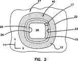
図2は、その投影領域を表す概略図である。
図3は、その投影領域を表す別概略図である。
図4は、前記実施例の外傷治療具と組み合せて使用する着脱式ヒーターの1例を示す斜視図である。
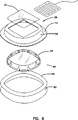
図5は、前記実施例の外傷治療具の分解図である。
図6は、本発明の外傷治療具の別実施例の分解図である。
図7は、ヒーターシステムの1例を示す斜視図である。
図8は、ヒーターシステム用の感圧スイッチの1例を示す電気構造図である。
図9Aは、本発明の外傷治療具に内蔵された状態の感圧スイッチの1例を示す分解図である。
図9Bは、前記の感圧スイッチの部分図である。
図10は、前記の外傷治療具用のパッシブヒーターの1実施例を示す斜視図である。
図11Aは、伸縮部の立体形状の1実施例を示す概略図である。
図11Bは、伸縮部の立体形状の別実施例を示す概略図である。
図11Cは、伸縮部の立体形状の別実施例を示す概略図である。
図11Dは、伸縮部の立体形状の別実施例を示す概略図である。
図12Aは、本発明の複数要素間の機能的関係を示す概略図である。
図12Bは、本発明の複数要素間の変形状態を示す概略図である。
図13Aは、本発明の複数要素間の機能的関係を示す別概略図である。
図13Bは、本発明の複数要素間の変形状態を示す概略図である。
図14Aは、本発明の複数要素間の機能的関係を示す別概略図である。
図14Bは、本発明の複数要素間の変形状態を示す概略図である。
図15は、本発明の外傷治療具の別例の斜視図である。
図16は、本発明の外傷治療具の別例の斜視図である。
図17Aは、ヒーターを備えた外傷治療具の別例の斜視図である。
図17Bは、ヒーターを備えた外傷治療具の別例の斜視図である。
図17Cは、外傷治療具の別例の斜視図である。
図18は、ヒーターを備えた外傷治療具の別例の斜視図である。
図19Aは、ヒーターを備えた外傷治療具の別例の斜視図である。
図19Bは、ヒーターを設置した外傷治療具の斜視図である。
図20Aは、ヒーターを備えた外傷治療具の別例の斜視図である。
図20Bは、ヒーターを設置した外傷治療具の斜視図である。
図21Aは、ヒーターを備えた外傷治療具の別例の斜視図である。
図21Bは、ヒーターを設置した外傷治療具の斜視図である。
図22Aは、ヒーターを備えた外傷治療具の別例の斜視図である。
図22Bは、ヒーターを設置した外傷治療具の斜視図である。
発明の詳細な説明
図1は患者の皮膚表面18に貼付された状態の外傷治療具10の斜視図である。
座標系11は患者の皮膚表面18に提供されており、X軸、Y軸、及びZ軸の方向を定義している。接着部12は平面状囲体あるいはフランジとして提供されている。接着部12は粘着剤によって患者の皮膚18に接着され、第1X−Y平面に配置される。この外傷治療具10の実施例においては、伸縮部16は接着部12と一体的に成型されている。伸縮部16はZ軸方向に皮膚表面から垂直に延び出ており、傷口治療部14と接続している。この実施例においては、傷治療部14は透明な平面傷口カバー20を有しており、傷口治療領域28を透視させる。
傷口カバー20はフォーム体の張出囲部15によって第1X−Y平面上方の別な第2X−Y平面にて支持されている。傷口カバー20と張出囲部15とは傷口治療部14を形成している。傷口治療面28上方の領域を傷口治療構造部24と呼称する。
この図においては、外傷治療具10は患者の皮膚に弛緩状態で貼付されている。
このような弛緩状態においては、接着部12の外側縁部22は明瞭に現れる。
内側縁部23は伸縮部16との折り目によって現れる。
図2と図3は連続図であり、外傷治療具10に対する患者の動作の影響を示している。図2と図3は図1の外傷治療具10の平面図であり、外傷治療具10の多様な部分が第1X−Y平面に投影されている。
図2において、傷口カバー部は弛緩状態で示されており、伸びていない状態の総投影領域27を有している。投影された傷口治療面28は外傷治療具10の中央に示されている。張出囲部15はその外縁部25と内縁部26とで囲まれた斜線領域で表されている。伸縮部の投影領域17は接着部12の内縁部23と、張出囲部15の内縁部26とで囲まれた部分として示されている。接着部の投影領域40は接着部12の外縁部22と内縁部23とで囲まれた斜線領域として示されている。
図3は、患者の動きによってX軸方向に伸ばされた状態の外傷治療具10を示している。図2と比較すると、外傷治療具10の総投影領域27は増大している。
接着部の投影領域40は、接着部12が下側の皮膚と共に移動するに従って少々増大する。投影された傷口治療面28の面積は本質的には増加しない。この実施例においては、張出囲部15は皮膚に対して自由に動けるからである。最大面積変化は伸縮部の投影領域17で発生する。患者の動きに伴って外傷治療具10が変形するとき、伸縮部は対応的に伸びる材料を提供し、増大した総投影領域27の大部分を主として伸縮部の投影領域17が担うからである。
図4はポケットカバー21によって形成されたポケット内へ挿入される着脱式ヒーター32を示している。ポケットカバー21は傷口カバー20に接着固定されており、ヒーター32を保持する大きさで提供されている。張出囲部15と傷口カバー20は外傷治療具10の形状安定に貢献しており、一方、伸縮部16は患者の動きに対処する。従って、ヒーター32は傷口面上で安定して固定される。
一般的に、単位面積あたりに一定の熱出力を提供する平型ヒーター32を使用することが望ましい。この形状のヒーターは傷口に対してほぼ均等な放射熱エネルギーを提供する。傷口領域に供給される熱量は、傷口面上からのヒーター32の高さにはほとんど無関係である。
図5は外傷治療具10の前述実施例の分解図である。接着部12と伸縮部壁膜36は一体型複合部材38として成型されている。複合部材38はボララ−6AS(Volara-6AS)のごとき閉孔ポリオレフィンフォーム材で真空成型が可能である。この材料はミネソタ州メープルズ市のイルブルック社(Illbruck Inc.)によって販売されているポリエチレン材料である。本発明においては多くの他材料でも代用は可能である。張出囲部15は網状ポリウレタンフォームのフォームシートから切出加工することが可能である。このフォーム体の吸収性と物性は、適用される特定の治療形態に合わせて随意に決定することができる。例えば、このフォーム製張出囲部を抗生物質、抗菌剤、あるいは抗病原菌剤等の薬剤で浸加工することができる。この張出囲部から消臭ガスや酸化窒素ガスを放出させることも望ましいであろう。傷口カバー20と傷口ポケット21はポリエチレンフィルムで加工することが可能である。一般的に、複合部材38にはある程度の剛性を提供し、外傷治療具10が引き剥されても、傷口治療部14が伸縮壁膜36の成型された屈曲接合部の形状を保って支持されるようにし、複合部材38を反転させるのにはある程度の力を必要とさせる。この特徴により複合部材の形状保持特性が提供され、たとえ、外傷治療具10が上下反対であっても張出囲部15は皮膚に対して刺激なく設置させる。大型傷口カバーの場合には、張出囲部の皮膚接触面に高粘着性の粘着剤を塗布することが望ましい。
図6は外傷治療具10の別実施例の分解図である。接着部12と伸縮壁膜36は一体型複合部材38として成型されている。この実施例においては、傷口治療構造体は鋸刃状張出囲部34によって提供されている。壁膜36はポリエチレン等のさらに剛性が高いプラスチック材料で製造するとよい。鋸刃形状44で示すような鋸刃形状は鋸刃状囲部をフレキシブルにしており、患者の動きに柔軟に対処する。この実施例では接着剤46で複合部材38の接着部12に接着された剥用ライナー体42が提供されている。ポケットカバー21は複合部材38に接着されている。
図7は外傷治療具10の加熱部の携帯用電力源を図示している。複数の小型電池を結束させて電力源48とし、ベルト49に取り付けるのが便利であろう。適当なケーブル50を使用してヒーター32に電力を提供する。傷口面を過度に加熱させないよう、外傷治療具10が変形したときにはヒーター32に対する電力供給を停止させることが望ましい。
図8は着脱式ヒーター32内に内蔵が可能なタッチスイッチを示す概略図である。ヒーター32には連続式抵抗型加熱コイル51が含まれている。導電膜52をコイル51に隣接させて配置し、コイル51を”ショートカット(short out)”させることができる。コイル52への電力はタッチセンサー53に対する押圧によってカットされる。
図9Aは図8に概略的に説明されているタイプのタッチスイッチを内蔵するヒーター32を示す分解図である。スイッチカバー45は加熱コイル51の導電回路パターン上に配置された導電膜52を有している。導電膜は接着帯体54で保持されている。図9Bはスイッチカバー45の裏側を示しており、導電膜52を加熱コイル51と間隔を保って保持するように隆起体47のごとき分離して提供された多数の絶縁隆起体を示している。スイッチカバー45に加えられた押圧は加熱コイル51の作用を停止させる。
図10は装着体(カバー)55を示している。これは傷口に面した反射面(reflective surface)を有したパッシブヒーターであってもよい。この装着体55をマッピンググリッド(mapping grid)とし、グリッドを透明カード上に配して傷治癒過程を観察させることもできる。
図11Aから図11Dは連続図である。これらの図面は本発明の要素の接続構造の説明をするためのものであり、いくつかの実施例による接続構造を示している。一般的に、患者の動作に対処するには、伸縮部が伸びる材料を提供して伸縮部の投影領域を増大させる。これら図面のそれぞれは、X−Z平面での外傷治療具10の概略断面図である。各図において、傷口カバーは弛緩状態にある。
図11Aは第1平面56から第2平面58へと延びている張出囲部15の断面を示す。伸縮部16は、接着部12と伸縮部16との交差部にて形成された第1フレキシブル接合部62を介して接着部12に接続された伸縮壁膜60を有している。伸縮壁膜60は、伸縮部16と傷口治療部14との交差部で形成された第2フレキシブル接合部64を介して傷口治療部14に接続されている。傷口治療部14は一般的に筒状構造であり、患者皮膚面の傷口治療領域を定義している。
最小相互間距離66は第1フレキシブル接合部62から第2フレキシブル接合部64に延びている破線で表されている。この最小距離66は伸縮壁膜60の最小壁長である。本発明の多数の実施例においては、第1フレキシブル接合部62と第2フレキシブル接合部64との間の伸縮部16の壁長は、これらの両接合部間の直線よりも長い。この関係は、弛緩状態で引っ張られていない状態の外傷治療具10において常に真である。第1平面56と第2平面58との垂直距離が、相互間距離66の最低値を表すことはもちろんである。X−Y平面において、フレキシブル接合部62と64はそれぞれ第1周縁部61と第2周縁部63とを定義する。図11Aに示す実施例においては、第1周縁部61は第2周縁部63よりも大きい。
図11Bは、別例の接続構造を有した外傷治療具10の概略断面図である。この実施例では、傷口カバー20は傷口治療構造体24を越えて放射状に延びており、第2周縁部68は第1周縁部71よりも大きい。この構造によりフレキシブルな伸縮部74が提供され、壁長が長いので伸縮性に富む。
図11Cは、第1周縁部76と第2周縁部78とがほぼ同じ大きさで、軸90に対して同心状態である接続構造を示している。この構造により波型伸縮部77が提供される。この場合も、伸縮部77の壁長は第1周縁部76と第2周縁部78との間の直線65よりも長い。
図11Dは傷口治療部14としての半球部材70を示している。この実施例においては、第2周縁部80は単一の接続点である。この実施例においては、第1周縁部81は第2周縁部80よりも大幅に長い。この構造により半球型伸縮部79が提供され、第2周縁部80と第1周縁部81との間の直線距離85を越える壁長を有している。
多様な立体構造のそれぞれの特徴により細部では異なるが、一般的には充分な剛性を備えているが充分にフレキシブルであって、形状の変化に対応できる変形機構を提供する弾力材料で伸縮部を形成することが好ましい。この柔軟性によって、外傷治療具10の傷口治療部14と接着部12との間でのせん断力の伝達が防止される。図11Aから図11Dにかけて示されるような立体構造により、外傷治療具10の伸縮部は、そのプリーツ形状、渦巻形状、あるいは蛇腹形状の壁膜で”材料”を収容保存することができる湾曲結合を提供する。このような構造は接着部12から傷口治療部14への力の伝達を最小とするような伸縮部の変形を可能にする。
図12Aから図14Bはそれぞれ連続図である。これらの実施例においては、張出囲部15は高さが減少しており、傷口治療具10の伸展時に伸縮部の伸展作用を促す。
図12Aは弛緩状態にある張出囲部15を有した外傷治療具10の一部を示している。この場合、伸縮部の投影領域17は距離88に比例する。図12Bにおいては、外傷治療具10は引き伸ばされており、張出囲部15はZ軸方向に縮小されている。伸縮部の投影領域の増大は距離91で示されている。
図13Aは弛緩状態にある鋸刃状囲部34を有した外傷治療具10の一部を示している。この場合、伸縮部の投影領域17は距離98に比例する。図13Bにおいて、外傷治療具は引き伸ばされており、鋸刃状囲部34の高さはZ軸方向に縮小されている。この鋸刃状壁部は引き広げられ、距離99で表されるように伸縮部の投影領域が増大している。
図14Aは弛緩状態にある張出囲部15を有した外傷治療具10の一部を示している。この構造においては、接着部12と伸縮壁膜96とは両方とも第1平面56に存在する。この場合、伸縮部の投影領域17は距離94に比例する。図14Bにおいては、外傷治療具10は引き伸ばされており、張出囲部15はZ軸方向に縮んでいる。この高さの減少は伸縮部の投影領域の増加をもたらし、距離92がこの関係を表している。
図15はドーム形状あるいは半球状の傷口カバー19を含んだ外傷治療具10を示している。この傷口カバーの少なくとも一部は第2X−Y平面58に存在している。
図16は着脱式傷口カバー20を含んだ外傷治療具10を示している。傷口にアクセスできるよう、傷口カバー20の周縁部に引出部29を提供することもできる。一般的に、何度も使用することが可能な粘着剤30を傷口カバー20の周辺部に塗布し、カバー20を張出囲部15または複合部材38に対して引き剥し可能に粘着させることもできる。
図17Aは加熱ポケットカバー21を採用した着脱式傷口カバー20を示している。傷口カバー20とポケットカバー21とはヒーター32設置用のスペースを提供している。
図17Bは、着脱構造の利点の1つが、外傷治療具10を取り去ったり、移動させる必要なくヒーター32を設置させることにあることを示している。
図17Cは斜面体形状の外傷治療具10を示している。X−Y平面11における接着部12の直線31は、張出囲部15の上側面を横断する直線33と交差する。これら直線は図面に示す空間の点35で交差するであろう。
図18は平型ヒーター32を傷口カバー20へ付着させる方法の別例を示している。この実施例においては、ヒーター32の周縁部にはフック型周縁材料39が提供されており、複合部材38の周縁部にはそれに係合する係合フック型周縁材料37が提供されている。この実施例においては、傷口カバー20はヒーターの姿勢調整のためにはアクセス可能である必要はない。粘着剤をヒーターの付着に使用することもできる。
図19Aはヒーターを備えた外傷治療具10の別実施例の斜視図である。この実施例においては、ヒーター83はドーム形状であり、傷口カバー84のドーム形状に合わせてある。相互に係合するフック型周縁材料37と39とを外傷治療具10に提供し、着脱式とすることも可能である。
図19Bは粘着剤等で外傷治療具に取り付けられたヒーターを備えた外傷治療具の斜視図である。この実施例においては、抵抗型ヒーターグリッドがカバー内に提供されており、リード線50を介した電気エネルギーに応じた熱を発生させる。
図20Aはドーム形状ヒーター86を備えた外傷治療具の別例の斜視図である。
この実施例においては、ヒーター86はループ線87のごとき独立して平行状態で接続された抵抗型ループ線の集合体を有している。使用の際にはループ線の抵抗度を選択し、放射熱が傷口面で均一となるようにする。
図20Bは外傷治療具10に搭載されたドーム型ヒーター86を備えた外傷治療具の斜視図である。
図21Aはドーム型ヒーター89を備えた外傷治療具の別例の斜視図である。この実施例では、ヒーターのワイヤーは渦巻形状に巻き付けられてヒーター要素を提供している。
図21Bはドーム型ヒーター89を搭載した外傷治療具の斜視図である。使用に際しては、距離87で示すコイル間隔を調整し、傷口領域に対して均等な温度を提供する。
図22Aは、ヒーター32に提供された引出部83と73と係合するポケット97と95とを有した外傷治療具10の斜視図である。
図22Bは平型ヒーターを配置して保持するようにポケット95とポケット97とにそれぞれ係合した引出部73と83とを示す斜視図である。
以上、図面を基にして本発明を説明してきたが、本請求の範囲に記載された本発明の範囲から逸脱せずに多数の変更を施すことは当然に可能である。Related Application For the US national phase, this application is a continuation-in-part of pending US patent application Ser. No. 08 / 342,741.
TECHNICAL FIELD The present invention relates to a trauma treatment device that covers skin wounds, surgical wounds, and the like and heat-treats those wounds as necessary.
The trauma treatment device includes a wound cover and optionally a removable wound heater to provide a non-contact wound treatment structure on the wound site.
The present invention also relates to a method for manufacturing and using the device for treating trauma.
BACKGROUND OF THE INVENTION One conventional method of treating trauma is to cover a wound with sterilized gauze and fix the gauze with an adhesive tape. This type of trauma treatment device has a number of drawbacks. The wound is not well blocked from the outside air and allows bacteria to enter. Gauze is easy to adhere to the wound and interfere with wound healing. Such conventional treatment tools cannot perform thermal control of wounds that adversely affect the therapeutic effect.
The existence of a wound heater and non-contact wound cover in the form disclosed in French Patent 1,527,887 (1969) by Veilhan is known, but for several reasons It has not been used generally. For example, a wound cover that includes a hard enclosure that provides a recess over the wound is typically secured to the patient's skin with a relatively hard adhesive material. As a result, the treatment device could not respond to the patient's movement and was easily peeled off from the patient's skin by the patient's movement. The traditional approach to this problem has been to use a stronger adhesive tape to keep the wound cover more firmly adhered to the patient's skin. This solution has caused an uncomfortable feeling of wearing the wound cover.
Further, the conventional wound cover cannot strictly control the temperature of the wound site.
Even if a point heat source type heater is used in a conventional heated trauma treatment device using a non-contact type enclosure, the radiant heat cannot be controlled due to the influence of the heater position in the enclosure.
Therefore, there has been a long-awaited appearance of a non-contact type wound treatment device that can control the wound environment and can be comfortably fixed to the skin without being easily peeled off.
SUMMARY OF THE INVENTION The
For the purpose of explaining the present invention, the
The bonding
The
The
A
The
[Brief description of the drawings]
In order to explain an embodiment of the present
FIG. 1 is a perspective view of one embodiment of the trauma treatment device of the present invention.
FIG. 2 is a schematic diagram showing the projection area.
FIG. 3 is another schematic diagram showing the projection area.
FIG. 4 is a perspective view showing an example of a detachable heater used in combination with the injury treatment device of the above embodiment.
FIG. 5 is an exploded view of the injury treatment device of the above embodiment.
FIG. 6 is an exploded view of another embodiment of the trauma treatment device of the present invention.
FIG. 7 is a perspective view showing an example of a heater system.
FIG. 8 is an electrical structural diagram showing an example of a pressure sensitive switch for a heater system.
FIG. 9A is an exploded view showing an example of a pressure-sensitive switch in a state of being incorporated in the wound treatment device of the present invention.
FIG. 9B is a partial view of the pressure sensitive switch.
FIG. 10 is a perspective view showing one embodiment of the passive heater for the above-mentioned trauma treatment tool.
FIG. 11A is a schematic diagram illustrating an example of the three-dimensional shape of the stretchable portion.
FIG. 11B is a schematic view showing another embodiment of the three-dimensional shape of the stretchable part.
FIG. 11C is a schematic view showing another embodiment of the three-dimensional shape of the expansion / contraction part.
FIG. 11D is a schematic diagram illustrating another example of the three-dimensional shape of the stretchable portion.
FIG. 12A is a schematic diagram showing a functional relationship between multiple elements of the present invention.
FIG. 12B is a schematic diagram showing a deformed state between a plurality of elements of the present invention.
FIG. 13A is another schematic diagram showing the functional relationship between multiple elements of the present invention.
FIG. 13B is a schematic view showing a deformed state between a plurality of elements of the present invention.
FIG. 14A is another schematic diagram illustrating the functional relationship between multiple elements of the present invention.
FIG. 14B is a schematic view showing a deformed state between a plurality of elements of the present invention.
FIG. 15 is a perspective view of another example of the trauma treatment device of the present invention.
FIG. 16 is a perspective view of another example of the trauma treatment device of the present invention.
FIG. 17A is a perspective view of another example of a trauma treatment device including a heater.
FIG. 17B is a perspective view of another example of a trauma treatment device including a heater.
FIG. 17C is a perspective view of another example of the trauma treatment tool.
FIG. 18 is a perspective view of another example of a trauma treatment device including a heater.
FIG. 19A is a perspective view of another example of a trauma treatment device including a heater.
FIG. 19B is a perspective view of a trauma treatment device provided with a heater.
FIG. 20A is a perspective view of another example of a trauma treatment device including a heater.
FIG. 20B is a perspective view of a trauma treatment device provided with a heater.
FIG. 21A is a perspective view of another example of a trauma treatment device including a heater.
FIG. 21B is a perspective view of a trauma treatment device provided with a heater.
FIG. 22A is a perspective view of another example of a trauma treatment device including a heater.
FIG. 22B is a perspective view of a trauma treatment device provided with a heater.
DETAILED DESCRIPTION OF THE INVENTION FIG. 1 is a perspective view of a
A coordinate
The wound cover 20 is supported by another extended XY plane above the first XY plane by the overhanging
In this figure, the
In such a relaxed state, the
The
2 and 3 are continuous views showing the effect of patient movement on the
In FIG. 2, the wound cover portion is shown in a relaxed state, and has a
FIG. 3 shows the
The projected
FIG. 4 shows a
In general, it is desirable to use a
FIG. 5 is an exploded view of the aforementioned embodiment of the
FIG. 6 is an exploded view of another embodiment of the
FIG. 7 illustrates a portable power source for the heating unit of the
FIG. 8 is a schematic view showing a touch switch that can be incorporated in the
9A is an exploded view showing a
FIG. 10 shows a mounting body (cover) 55. This may be a passive heater with a reflective surface facing the wound. The mounting
11A to 11D are continuous diagrams. These drawings are for explaining the connection structure of the elements of the present invention, and show the connection structure according to some embodiments. In general, to cope with patient motion, a material from which the stretchable part extends is provided to increase the projection area of the stretchable part. Each of these drawings is a schematic cross-sectional view of the
FIG. 11A shows a cross section of the overhanging
The
FIG. 11B is a schematic cross-sectional view of a
FIG. 11C shows a connection structure in which the first
FIG. 11D shows a
Although the details differ depending on the characteristics of various three-dimensional structures, in general, the elastic part has sufficient rigidity but is flexible enough to provide a deformation mechanism that can respond to changes in shape. It is preferable to form. Due to this flexibility, transmission of shear force between the
12A to 14B are continuous diagrams. In these embodiments, the overhanging
FIG. 12A shows a part of the
FIG. 13A shows a part of the
FIG. 14A shows a part of the
FIG. 15 shows the
FIG. 16 shows the
FIG. 17A shows a detachable wound cover 20 that employs a
FIG. 17B shows that one of the advantages of the detachable structure is that the
FIG. 17C shows the
FIG. 18 shows another example of a method for attaching the
FIG. 19A is a perspective view of another embodiment of the
FIG. 19B is a perspective view of a trauma treatment device including a heater attached to the trauma treatment device with an adhesive or the like. In this embodiment, a resistive heater grid is provided in the cover and generates heat according to the electrical energy through the
FIG. 20A is a perspective view of another example of a trauma treatment device provided with a dome-shaped
In this embodiment, the
FIG. 20B is a perspective view of a trauma treatment device including a
FIG. 21A is a perspective view of another example of a trauma treatment device provided with a dome-shaped
FIG. 21B is a perspective view of a wound treatment device equipped with a dome-shaped
FIG. 22A is a perspective view of the
FIG. 22B is a perspective view showing the
While the invention has been described with reference to the drawings, it will be appreciated that numerous changes can be made without departing from the scope of the invention as set forth in the claims.
Claims (56)
前記患者皮膚面上に傷口治療領域を定義し、該傷口治療領域上方の非接触型傷口治療構造体を定義している傷口治療部と、
該傷口治療部は前記第1平面から第2平面まで延びる張出囲部を含んだものであり、前記張出囲部は着脱式電気ヒーターを保持する大きさで提供され、本外傷治療具は、前記接着部と前記傷口治療部とを連結しており、前記第1平面に隣接して前記接着部に接合され、さらに前記張出囲部に接合された壁膜を含んだ伸縮部をさらに含んでおり、
前記患者皮膚表面に投影された前記接着部は投影接着領域を定義し、前記患者皮膚表面に投影された前記傷口治療部は投影傷口治療領域を定義し、前記患者皮膚表面に投影された前記伸縮部は投影伸縮領域を定義しており、
前記傷口治療構造体は前記第1弛緩状態に対応する第1総投影領域と、前記第2伸張状態に対応する増大した第2総投影領域とを有しており、該第2総投影領域は前記第1総投影領域よりも広いものであり、
前記第2総投影領域は前記伸縮部の形状変動の結果として提供されるものであることを特徴とする外傷治療具。A trauma treatment tool that is applied to a skin surface of a patient and adapted to a stretching operation of the patient skin surface from a first relaxed state to a second stretched state, the patient skin surface defining a first plane; The wound adhesive part present in contact;
Defining a wound treatment area on the patient's skin surface, and defining a non-contact type wound treatment structure above the wound treatment area;
The wound treatment unit includes an overhanging portion extending from the first plane to the second plane, and the overhanging portion is provided in a size for holding a detachable electric heater. The adhesive part and the wound treatment part are connected to each other, and a stretchable part including a wall film joined to the adhesive part adjacent to the first plane and further joined to the overhanging part is further provided. Including
The adhesion part projected onto the patient skin surface defines a projected adhesion area, the wound treatment part projected onto the patient skin surface defines a projection wound treatment area, and the expansion and contraction projected onto the patient skin surface Part defines the projected stretch area,
The wound treatment structure has a first total projection region corresponding to the first relaxed state and an increased second total projection region corresponding to the second stretched state, the second total projection region being Wider than the first total projected area,
The trauma treatment tool, wherein the second total projection region is provided as a result of a shape variation of the stretchable part.
前記第1接合部と前記第2接合部との直線距離は相互間の最少接続距離を定義しており、
前記成型屈曲接合膜は前記第1接合部と前記第2接合部との間に延び広がって提供されており、本外傷治療具が前記弛緩状態にあるとき、前記最小接続距離より長い曲線長を有しており、
前記伸縮部の前記投影領域の増大は、前記成型屈曲接合膜の前記曲線長の伸張により提供されることを特徴とする請求項1記載の外傷治療具。The stretchable part is connected to the adhesive part at a first joint adjacent to the first plane, and is connected to the overhanging part at a second joint adjacent to the second plane. Including a molded bending bonding membrane,
The linear distance between the first joint and the second joint defines a minimum connection distance between each other,
The molded bending bonding film is provided to extend between the first bonding portion and the second bonding portion, and when the trauma treatment device is in the relaxed state, a curve length longer than the minimum connection distance is provided. Have
The trauma treatment device according to claim 1, wherein an increase in the projection area of the stretchable part is provided by extension of the curved length of the molded bending bonding film.
前記第1接合部と前記第2接合部との直線距離は相互間の最少接続距離を定義しており、
前記成型屈曲接合膜は前記第1接合部と前記第2接合部との間に延び広がって提供されており、前記最小接続距離より長い曲線長を有しており、
前記伸縮部の前記投影領域の増大は、前記成型屈曲接合膜の前記曲線長の伸張と、前記張出囲部の高さの減少とにより提供されることを特徴とする請求項5記載の外傷治療具。The stretchable part is connected to the adhesive part at a first joint adjacent to the first plane, and is connected to the overhanging part at a second joint adjacent to the second plane. Including a molded bending bonding membrane,
The linear distance between the first joint and the second joint defines a minimum connection distance between each other,
The molded bending bonding film is provided to extend between the first bonding portion and the second bonding portion, and has a curve length longer than the minimum connection distance,
6. The trauma according to claim 5, wherein an increase in the projection area of the stretchable part is provided by an extension of the curved length of the molded bent joint film and a decrease in the height of the overhanging part. Treatment tool.
前記伸縮部の前記投影領域の増大は主として前記張出囲部の高さの減少により提供されることを特徴とする請求項5記載の外傷治療具。The expansion / contraction part includes a relatively hard wall film that is connected to the overhanging part adjacent to the second plane and connected to the adhesive part adjacent to the first plane. And
6. The trauma treatment tool according to claim 5, wherein an increase in the projection area of the stretchable part is mainly provided by a decrease in the height of the overhanging part.
前記伸縮部の前記投影領域の増大は主として前記張出囲部の高さの減少により提供されることを特徴とする請求項6記載の外傷治療具。The expansion / contraction part includes a relatively hard wall film that is connected to the overhanging part adjacent to the second plane and connected to the adhesive part adjacent to the first plane. And
The trauma treatment tool according to claim 6, wherein an increase in the projection area of the stretchable part is mainly provided by a decrease in the height of the overhanging part.
前記第2平面に少なくともその一部を存在させ、閉囲された傷口治療構造体を提供するように少なくとも前記内壁をカバーする大きさの傷口カバーとを含んでいることを特徴とする請求項1記載の外傷治療具。The wound treatment unit is a resin foam cylinder having an inner wall and an outer wall provided extending from the first plane to the second plane, respectively,
2. A wound cover sized to cover at least the inner wall so as to provide at least a portion thereof in the second plane and to provide a closed wound treatment structure. The described trauma treatment tool.
前記第2平面に実質的に存在し、閉囲された傷口治療構造体を提供するように少なくとも前記内壁をカバーする大きさの傷口カバーとを含んでいることを特徴とする請求項1記載の外傷治療具。The wound treatment unit is a resin foam cylinder having an inner wall and an outer wall provided extending from the first plane to the second plane, respectively,
A wound cover sized to cover at least the inner wall so as to provide a closed wound treatment structure substantially in the second plane. Trauma treatment tool.
該樹脂製筒体は前記第2平面に少なくとも部分的に存在する単一カバー部材を有しており、閉囲された傷口治療構造体を提供していることを特徴とする請求項1記載の外傷治療具。The wound treatment part includes a resin cylinder having a wall part that defines an overhanging part provided to extend from the first plane to the second plane,
The said resin cylinder has a single cover member which exists at least partially in the said 2nd plane, The closed wound treatment structure is provided of Claim 1 characterized by the above-mentioned. Trauma treatment tool.
該第1平面から第2平面にまで延び広がって提供されており、該第1平面に存在する傷口治療領域の上方にて傷口治療構造体を定義している張出囲部と、該張出囲部の上方に前記傷口治療領域に対して実質的に均等な放射熱を提供する電気ヒーターを有していることを特徴とする外傷治療具。A wound treatment tool to be applied to a patient's skin surface, the wound adhesive part existing in contact with the patient's skin surface defining a first plane;
A bulge that extends from the first plane to the second plane and that defines a wound treatment structure above the wound treatment area in the first plane; and An injury treatment device comprising an electric heater for providing substantially uniform radiant heat to the wound treatment area above the enclosure.
樹脂フォーム筒体を有しており、前記第1平面から第2平面にまで延び広がって提供され、該第1平面に存在する傷口治療領域の上方にて傷口治療構造体を定義している張出囲部と、
該張出囲部に近接して設置され、前記傷口治療領域に放射熱を提供する電気ヒーターとを含んでいることを特徴とする外傷治療具。A wound treatment tool to be applied to a patient's skin surface, the wound adhesive part existing in contact with the patient's skin surface defining a first plane;
A stretch having a resin foam cylinder and extending from the first plane to the second plane and defining a wound treatment structure above the wound treatment area in the first plane The surrounding area,
A trauma treatment tool, comprising: an electric heater which is installed in the vicinity of the overhanging portion and provides radiant heat to the wound treatment area.
前記第1平面から第2平面にまで延び広がって提供され、傷口治療領域の上方にて傷口治療構造体を定義している張出囲部と、
該張出囲部と前記接着部とに連結されている伸縮部と、
前記傷口治療領域に対して反射熱を提供するために前記張出囲部に隣接して提供されている熱反射器とを含んでいることを特徴とする外傷治療具。A wound treatment tool to be applied to a patient's skin surface, the wound adhesive part existing in contact with the patient's skin surface defining a first plane;
An overhang provided to extend from the first plane to the second plane and defining a wound treatment structure above the wound treatment area;
A telescopic part connected to the overhanging part and the adhesive part;
A wound treatment device comprising: a heat reflector provided adjacent to the overhanging portion to provide reflected heat to the wound treatment area.
Applications Claiming Priority (3)
| Application Number | Priority Date | Filing Date | Title |
|---|---|---|---|
| US08/342,741 | 1994-11-21 | ||
| US08/342,741 US5817145A (en) | 1994-11-21 | 1994-11-21 | Wound treatment device |
| PCT/US1995/015197 WO1996015745A2 (en) | 1994-11-21 | 1995-11-21 | Wound treatment device for attachment to skin |
Publications (2)
| Publication Number | Publication Date |
|---|---|
| JPH10509886A JPH10509886A (en) | 1998-09-29 |
| JP3918158B2 true JP3918158B2 (en) | 2007-05-23 |
Family
ID=23343082
Family Applications (1)
| Application Number | Title | Priority Date | Filing Date |
|---|---|---|---|
| JP51705496A Expired - Fee Related JP3918158B2 (en) | 1994-11-21 | 1995-11-21 | Trauma treatment tool for skin application |
Country Status (7)
| Country | Link |
|---|---|
| US (8) | US5817145A (en) |
| EP (2) | EP0793467B1 (en) |
| JP (1) | JP3918158B2 (en) |
| AT (2) | ATE288244T1 (en) |
| CA (1) | CA2204159C (en) |
| DE (2) | DE69535208T2 (en) |
| WO (1) | WO1996015745A2 (en) |
Families Citing this family (201)
| Publication number | Priority date | Publication date | Assignee | Title |
|---|---|---|---|---|
| US6406448B1 (en) | 1992-06-19 | 2002-06-18 | Augustine Medical, Inc. | Normothermic heater covering for tissue treatment |
| US5947914A (en) * | 1995-02-21 | 1999-09-07 | Augustine Medical, Inc. | Wound covering |
| US5954680A (en) | 1992-06-19 | 1999-09-21 | Augustine Medical, Inc. | Near hyperthermic heater wound covering |
| US5986163A (en) * | 1992-06-19 | 1999-11-16 | Augustine Medical, Inc. | Normothermic heater wound covering |
| US5964723A (en) | 1992-06-19 | 1999-10-12 | Augustine Medical, Inc. | Normothermic tissue heating wound covering |
| US6465708B1 (en) | 1992-06-19 | 2002-10-15 | Augustine Medical, Inc. | Covering |
| US7928281B2 (en) | 1992-06-19 | 2011-04-19 | Arizant Technologies Llc | Wound covering |
| US7537605B2 (en) * | 1993-10-04 | 2009-05-26 | Huan-Chen Li | Medical device for treating skin itch and rash |
| US6110197A (en) | 1994-11-21 | 2000-08-29 | Augustine Medical, Inc. | Flexible non-contact wound treatment device with a single joint |
| US5817145A (en) * | 1994-11-21 | 1998-10-06 | Augustine Medical, Inc. | Wound treatment device |
| US6093160A (en) | 1994-11-21 | 2000-07-25 | Augustine Medical, Inc. | Flexible non-contact wound treatment device |
| AU5711698A (en) * | 1996-12-18 | 1998-07-15 | Vidacare International, Inc. | Surgical healing mesh |
| IL120910A (en) | 1997-05-26 | 2004-01-04 | Lrr & D Ltd | Multipurpose dynamic occlusive dressing |
| US6143945A (en) * | 1998-04-06 | 2000-11-07 | Augustine Medical, Inc. | Bandage for autolytic wound debridement |
| US6420623B2 (en) | 1998-04-06 | 2002-07-16 | Augustine Medical, Inc. | Bandage for autolytic wound debridement |
| US6071304A (en) * | 1998-04-06 | 2000-06-06 | Augustine Medical, Inc. | Wound treatment apparatus with a heater adhesively joined to a bandage |
| US6213965B1 (en) * | 1998-04-06 | 2001-04-10 | Augustine Medical, Inc. | Wound treatment apparatus with infrared absorptive wound cover |
| US6095992A (en) * | 1998-04-06 | 2000-08-01 | Augustine Medical, Inc. | Wound treatment apparatus for normothermic treatment of wounds |
| US6235047B1 (en) * | 1998-04-06 | 2001-05-22 | Augustine Medical, Inc. | Wound treatment apparatus with a heater, a heat conductive bandage, and heat-spreading means acting between the heater and bandage |
| TW406018B (en) * | 1998-05-21 | 2000-09-21 | Elan Corp Plc | Improved adhesive system for medical devices |
| US6527979B2 (en) | 1999-08-27 | 2003-03-04 | Corazon Technologies, Inc. | Catheter systems and methods for their use in the treatment of calcified vascular occlusions |
| US6458109B1 (en) | 1998-08-07 | 2002-10-01 | Hill-Rom Services, Inc. | Wound treatment apparatus |
| EP1092404A1 (en) | 1999-10-11 | 2001-04-18 | Eurovita AG | Wound covering |
| US7087807B2 (en) * | 1999-11-10 | 2006-08-08 | Arizant Technologies, Llc | Tissue treatment device for an extremity |
| US6824533B2 (en) | 2000-11-29 | 2004-11-30 | Hill-Rom Services, Inc. | Wound treatment apparatus |
| ATE400315T1 (en) | 1999-11-29 | 2008-07-15 | Hill Rom Services Inc | DEVICE FOR TREATING A WOUND |
| US6764462B2 (en) | 2000-11-29 | 2004-07-20 | Hill-Rom Services Inc. | Wound treatment apparatus |
| US6528696B1 (en) * | 2000-01-11 | 2003-03-04 | Christine M. Ireland | Pliable contact bandage |
| US20010049546A1 (en) * | 2000-02-08 | 2001-12-06 | Israel Dvoretzky | Multi-purpose drug and heat therapy treatment system |
| EP1294325B1 (en) | 2000-05-22 | 2008-09-10 | Arthur C. Coffey | Combination sis and vacuum bandage |
| EP2248543A1 (en) * | 2000-08-24 | 2010-11-10 | Cordis Corporation | Fluid delivery systems for delivering fluids to multi-lumen catheters |
| US6416534B1 (en) | 2000-10-10 | 2002-07-09 | Sunbeam Products, Inc. | Portable heating pad with removable heat pad, removable gel pack and pressure bladder |
| US6685681B2 (en) | 2000-11-29 | 2004-02-03 | Hill-Rom Services, Inc. | Vacuum therapy and cleansing dressing for wounds |
| US6855135B2 (en) * | 2000-11-29 | 2005-02-15 | Hill-Rom Services, Inc. | Vacuum therapy and cleansing dressing for wounds |
| US6432077B1 (en) | 2000-12-26 | 2002-08-13 | Sensormedics Corporation | Device and method for treatment of surface infections with nitric oxide |
| EP1397096B1 (en) * | 2001-05-10 | 2005-07-27 | Arizant Healthcare Inc. | Minimal contact wound treatment device |
| EP2204213B2 (en) * | 2001-07-12 | 2020-04-01 | KCI Licensing, Inc. | Control of vacuum level rate of change |
| CA2462877A1 (en) | 2001-10-11 | 2003-04-17 | Hill-Rom Services, Inc. | Waste container for negative pressure therapy |
| US6699266B2 (en) | 2001-12-08 | 2004-03-02 | Charles A. Lachenbruch | Support surface with phase change material or heat tubes |
| WO2003057070A2 (en) * | 2001-12-26 | 2003-07-17 | Hill-Rom Services Inc. | Vented vacuum bandage and method |
| CA2468309A1 (en) | 2001-12-26 | 2003-07-17 | Robert Petrosenko | Wound vacuum therapy dressing kit |
| ATE387919T1 (en) * | 2001-12-26 | 2008-03-15 | Hill Rom Services Inc | VACUUM BAND PACKAGING |
| EP1487389B1 (en) * | 2002-02-28 | 2011-10-05 | KCI Medical Resources | External catheter access to vacuum bandage |
| CA2481016C (en) | 2002-04-10 | 2012-04-03 | Hill-Rom Services, Inc. | Access openings in vacuum bandage |
| US7083818B2 (en) * | 2002-08-16 | 2006-08-01 | Apio, Inc. | Party tray |
| AU2002359833A1 (en) | 2002-08-21 | 2004-03-11 | Hill-Rom Services, Inc. | Wound packing for preventing wound closure |
| US7846141B2 (en) | 2002-09-03 | 2010-12-07 | Bluesky Medical Group Incorporated | Reduced pressure treatment system |
| GB0224986D0 (en) | 2002-10-28 | 2002-12-04 | Smith & Nephew | Apparatus |
| US6772825B2 (en) | 2002-11-04 | 2004-08-10 | Charles A. Lachenbruch | Heat exchange support surface |
| CN1708265A (en) * | 2002-11-06 | 2005-12-14 | 宝洁公司 | Kits comprising body compress and releasably attached thermic cells |
| US7265256B2 (en) | 2003-01-17 | 2007-09-04 | Ther Memorial Hospital | Bandaging device for sequestering a wound or inoculation site |
| DE50300084D1 (en) * | 2003-02-18 | 2004-11-04 | Knoglinger Johann | Device for generating concentric temperature waves on the surface of the skin |
| US7169151B1 (en) * | 2003-04-10 | 2007-01-30 | Kci Licensing, Inc. | Bone regeneration device for long bones, and method of use |
| US7137979B2 (en) * | 2003-05-31 | 2006-11-21 | Tyrell, Inc. | Methods and devices for the treatment of skin lesions |
| US7160316B2 (en) * | 2003-09-24 | 2007-01-09 | Dynatherm Medical, Inc. | Methods and apparatus for adjusting body core temperature |
| US8182521B2 (en) | 2003-09-24 | 2012-05-22 | Dynatherm Medical Inc. | Methods and apparatus for increasing blood circulation |
| US20050085757A1 (en) * | 2003-10-15 | 2005-04-21 | Steven Santanello | Expandable temporary abdominal closure |
| GB0325129D0 (en) | 2003-10-28 | 2003-12-03 | Smith & Nephew | Apparatus in situ |
| US7238196B2 (en) * | 2003-10-31 | 2007-07-03 | Avery Dennison Corporation | Skin-contacting heatable dressing |
| US20050131501A1 (en) * | 2003-12-15 | 2005-06-16 | Rowland Robert A.Iii | Apparatus and method for prevention and treatment of infection |
| US7909805B2 (en) | 2004-04-05 | 2011-03-22 | Bluesky Medical Group Incorporated | Flexible reduced pressure treatment appliance |
| US10058642B2 (en) | 2004-04-05 | 2018-08-28 | Bluesky Medical Group Incorporated | Reduced pressure treatment system |
| US8062272B2 (en) | 2004-05-21 | 2011-11-22 | Bluesky Medical Group Incorporated | Flexible reduced pressure treatment appliance |
| GB0409446D0 (en) | 2004-04-28 | 2004-06-02 | Smith & Nephew | Apparatus |
| US7938122B2 (en) * | 2004-11-17 | 2011-05-10 | Asteame Medical Devices Inc. | Device and method for nipple reconstruction |
| WO2006086513A2 (en) * | 2005-02-08 | 2006-08-17 | Carewave, Inc. | Apparatus and method for using a portable thermal device to reduce accommodation of nerve receptors |
| US8067662B2 (en) * | 2009-04-01 | 2011-11-29 | Aalnex, Inc. | Systems and methods for wound protection and exudate management |
| US7745683B2 (en) * | 2005-04-16 | 2010-06-29 | Aalnex, Inc. | Deformable and conformable wound protecting apparatus and its method of application |
| US8415523B2 (en) | 2005-04-16 | 2013-04-09 | Aalnex, Inc. | Secondary wound dressings for securing primary dressings and managing fluid from wounds, and methods of using same |
| KR20080039340A (en) * | 2005-05-18 | 2008-05-07 | 타이렐, 인코포레이티드 | Treatment device and method for treating skin lesions through application of heat |
| CA2619929A1 (en) | 2005-09-06 | 2007-03-15 | Tyco Healthcare Group Lp | Self contained wound dressing with micropump |
| US20070068916A1 (en) * | 2005-09-29 | 2007-03-29 | Augustine Scott D | Heating blanket cover construction and methods of manufacture |
| AU2006299636A1 (en) * | 2005-09-29 | 2007-04-12 | Augustine Biomedical And Design Llc | Heating blanket and pads |
| US7543344B2 (en) * | 2005-09-29 | 2009-06-09 | Augustine Biomedical And Design Llc | Cover for a heating blanket |
| US7851729B2 (en) * | 2005-09-29 | 2010-12-14 | Augustine Temperature Management LLC | Electric warming blanket having optimized temperature zones |
| US8586818B2 (en) * | 2005-12-15 | 2013-11-19 | Aalnex, Inc. | Wound shield |
| US7622629B2 (en) | 2005-12-15 | 2009-11-24 | Aalnex, Inc. | Wound shield for exudate management |
| US7863495B2 (en) | 2006-01-12 | 2011-01-04 | Aalnex, Inc. | Dressing substrate |
| US7601129B2 (en) | 2005-12-15 | 2009-10-13 | Aalnex, Inc. | Wound shield and warming apparatus and method |
| US7816577B2 (en) * | 2006-02-13 | 2010-10-19 | Aalnex, Inc. | Wound shield |
| US7779625B2 (en) | 2006-05-11 | 2010-08-24 | Kalypto Medical, Inc. | Device and method for wound therapy |
| US9132031B2 (en) | 2006-09-26 | 2015-09-15 | Zeltiq Aesthetics, Inc. | Cooling device having a plurality of controllable cooling elements to provide a predetermined cooling profile |
| CA2964674A1 (en) | 2006-09-28 | 2008-03-28 | Smith & Nephew, Inc. | Portable wound therapy system |
| US8062343B2 (en) * | 2006-10-13 | 2011-11-22 | Augustine Temperature Management LLC | Heating blanket |
| US7931651B2 (en) | 2006-11-17 | 2011-04-26 | Wake Lake University Health Sciences | External fixation assembly and method of use |
| US8603150B2 (en) | 2006-12-04 | 2013-12-10 | Carefusion 2200, Inc. | Methods and apparatus for adjusting blood circulation |
| US9308148B2 (en) | 2006-12-04 | 2016-04-12 | Thermatx, Inc. | Methods and apparatus for adjusting blood circulation |
| US7862598B2 (en) | 2007-10-30 | 2011-01-04 | The Invention Science Fund I, Llc | Devices and systems that deliver nitric oxide |
| US20090112197A1 (en) * | 2007-10-30 | 2009-04-30 | Searete Llc | Devices configured to facilitate release of nitric oxide |
| US8642093B2 (en) | 2007-10-30 | 2014-02-04 | The Invention Science Fund I, Llc | Methods and systems for use of photolyzable nitric oxide donors |
| US8221690B2 (en) | 2007-10-30 | 2012-07-17 | The Invention Science Fund I, Llc | Systems and devices that utilize photolyzable nitric oxide donors |
| US8377016B2 (en) | 2007-01-10 | 2013-02-19 | Wake Forest University Health Sciences | Apparatus and method for wound treatment employing periodic sub-atmospheric pressure |
| US8624164B2 (en) * | 2007-01-18 | 2014-01-07 | Augustine Temperature Management LLC | Shut-off timer for a heating blanket |
| EP2129409B2 (en) | 2007-03-14 | 2021-11-24 | The Board of Trustees of the Leland Stanford Junior University | Devices for application of reduced pressure therapy |
| US8283602B2 (en) | 2007-03-19 | 2012-10-09 | Augustine Temperature Management LLC | Heating blanket |
| US10201935B2 (en) | 2007-03-19 | 2019-02-12 | Augustine Temperature Management LLC | Electric heating pad |
| US20150366367A1 (en) | 2007-03-19 | 2015-12-24 | Augustine Temperature Management LLC | Electric heating pad with electrosurgical grounding |
| MX2009009965A (en) * | 2007-03-20 | 2009-10-08 | Wyeth Corp | Thermal device. |
| US9107753B2 (en) | 2007-05-24 | 2015-08-18 | Ziivaa Ip, Llc | Method to relieve menstrual pain |
| US10149780B2 (en) * | 2007-05-24 | 2018-12-11 | Ziivaa Ip, Llc | Compression undergarment for relief of menstrual pain and related method of use |
| US20080289623A1 (en) * | 2007-05-24 | 2008-11-27 | Lee Stephen D | Therapeutic compression belt |
| US8191550B2 (en) * | 2007-05-24 | 2012-06-05 | Embrace, Llc | Method and apparatus to relieve menstrual pain |
| GB0712763D0 (en) | 2007-07-02 | 2007-08-08 | Smith & Nephew | Apparatus |
| BRPI0817544A2 (en) | 2007-10-10 | 2017-05-02 | Univ Wake Forest Health Sciences | apparatus for treating damaged spinal cord tissue |
| US20090099630A1 (en) * | 2007-10-12 | 2009-04-16 | Augustine Biomedical And Design Llc | Tuckable electric warming blanket for patient warming |
| US7846400B2 (en) | 2007-10-30 | 2010-12-07 | The Invention Science Fund I, Llc | Substrates for nitric oxide releasing devices |
| US8877508B2 (en) | 2007-10-30 | 2014-11-04 | The Invention Science Fund I, Llc | Devices and systems that deliver nitric oxide |
| US10080823B2 (en) | 2007-10-30 | 2018-09-25 | Gearbox Llc | Substrates for nitric oxide releasing devices |
| US7897399B2 (en) * | 2007-10-30 | 2011-03-01 | The Invention Science Fund I, Llc | Nitric oxide sensors and systems |
| US8980332B2 (en) | 2007-10-30 | 2015-03-17 | The Invention Science Fund I, Llc | Methods and systems for use of photolyzable nitric oxide donors |
| EP3254650B1 (en) | 2007-11-21 | 2020-01-08 | Smith & Nephew plc | Wound dressing |
| EP2217298B1 (en) | 2007-11-21 | 2015-11-11 | T.J. Smith & Nephew Limited | Suction device and dressing |
| GB0722820D0 (en) | 2007-11-21 | 2008-01-02 | Smith & Nephew | Vacuum assisted wound dressing |
| US8808274B2 (en) | 2007-11-21 | 2014-08-19 | Smith & Nephew Plc | Wound dressing |
| GB0723872D0 (en) | 2007-12-06 | 2008-01-16 | Smith & Nephew | Apparatus for topical negative pressure therapy |
| US8579953B1 (en) | 2007-12-07 | 2013-11-12 | Peter J. Dunbar | Devices and methods for therapeutic heat treatment |
| WO2009089435A1 (en) | 2008-01-09 | 2009-07-16 | Wake Forest University Health Sciences | Device and method for treating central nervous system pathology |
| WO2009093169A1 (en) * | 2008-01-22 | 2009-07-30 | Koninklijke Philips Electronics N.V. | Device for the topical delivery of nitric oxide to a skin surface |
| EP2586471B1 (en) | 2008-02-14 | 2019-04-24 | KCI Licensing, Inc. | Devices and methods for treatment of damaged tissue |
| GB0803564D0 (en) | 2008-02-27 | 2008-04-02 | Smith & Nephew | Fluid collection |
| US8021347B2 (en) | 2008-07-21 | 2011-09-20 | Tyco Healthcare Group Lp | Thin film wound dressing |
| US9033942B2 (en) | 2008-03-07 | 2015-05-19 | Smith & Nephew, Inc. | Wound dressing port and associated wound dressing |
| US8298200B2 (en) | 2009-06-01 | 2012-10-30 | Tyco Healthcare Group Lp | System for providing continual drainage in negative pressure wound therapy |
| US7825289B2 (en) * | 2008-05-16 | 2010-11-02 | Tyco Healthcare Group Lp | Wound dressing adhesive compression device |
| US8414519B2 (en) | 2008-05-21 | 2013-04-09 | Covidien Lp | Wound therapy system with portable container apparatus |
| US10912869B2 (en) | 2008-05-21 | 2021-02-09 | Smith & Nephew, Inc. | Wound therapy system with related methods therefor |
| US8177763B2 (en) | 2008-09-05 | 2012-05-15 | Tyco Healthcare Group Lp | Canister membrane for wound therapy system |
| RU2544093C2 (en) | 2008-07-18 | 2015-03-10 | Уэйк Форест Юниверсити Хелс Сайенсиз | Device and method for cardiac tissue modulation by local application of pressure below atmospheric for minimising cell death and injury |
| NO2309961T3 (en) | 2008-08-08 | 2018-05-05 | ||
| US8827983B2 (en) | 2008-08-21 | 2014-09-09 | Smith & Nephew, Inc. | Sensor with electrical contact protection for use in fluid collection canister and negative pressure wound therapy systems including same |
| DE102008041785B4 (en) | 2008-09-03 | 2011-07-21 | Pistor, Gert, Priv.-Doz. Dr., 10709 | Wound protection and its use |
| EP2161011B2 (en) | 2008-09-03 | 2015-05-20 | Gert Pistor | Wound protection |
| US20100100090A1 (en) | 2008-10-17 | 2010-04-22 | Medicold Limited | Thermotherapy application and control system |
| JP5680544B2 (en) | 2008-11-25 | 2015-03-04 | スパイラキュア インコーポレイテッド | Device for delivering reduced pressure to the body surface |
| US20100161016A1 (en) * | 2008-12-19 | 2010-06-24 | Augustine Biomedical And Design, Llc | Apparatus and method for effectively warming a patient |
| WO2010080907A1 (en) | 2009-01-07 | 2010-07-15 | Spiracur Inc. | Reduced pressure therapy of the sacral region |
| US8162907B2 (en) | 2009-01-20 | 2012-04-24 | Tyco Healthcare Group Lp | Method and apparatus for bridging from a dressing in negative pressure wound therapy |
| US20100210984A1 (en) * | 2009-02-19 | 2010-08-19 | Chien-Chou Chen | Electro-thermal protecting device for heat treatment |
| US8702774B2 (en) | 2009-04-30 | 2014-04-22 | Zeltiq Aesthetics, Inc. | Device, system and method of removing heat from subcutaneous lipid-rich cells |
| CN104095709B (en) | 2009-06-16 | 2017-06-13 | 3M创新有限公司 | Conformable Medical with self-supporting substrate |
| US20100324516A1 (en) | 2009-06-18 | 2010-12-23 | Tyco Healthcare Group Lp | Apparatus for Vacuum Bridging and/or Exudate Collection |
| US8252971B2 (en) | 2009-07-16 | 2012-08-28 | Aalnex, Inc. | Systems and methods for protecting incisions |
| EP3520830B1 (en) | 2009-12-22 | 2023-10-18 | Smith & Nephew, Inc. | Apparatuses for negative pressure wound therapy |
| CN102917674A (en) | 2010-01-08 | 2013-02-06 | 康尔福盛2200公司 | Methods and apparatus for enhancing vascular access in an appendage to enhance therapeutic and interventional procedures |
| GB201006323D0 (en) | 2010-04-15 | 2010-06-02 | Systagenix Wound Man Ip Co Bv | Leakage-reducing dressing |
| US9061095B2 (en) | 2010-04-27 | 2015-06-23 | Smith & Nephew Plc | Wound dressing and method of use |
| USRE48117E1 (en) | 2010-05-07 | 2020-07-28 | Smith & Nephew, Inc. | Apparatuses and methods for negative pressure wound therapy |
| US8591447B2 (en) | 2010-06-29 | 2013-11-26 | Jennifer DiGrazia | Wound and bandage protection system and method |
| US8721700B2 (en) * | 2010-08-20 | 2014-05-13 | Gene Stuffel | Therapeutic heated pocket |
| CA140188S (en) | 2010-10-15 | 2011-11-07 | Smith & Nephew | Medical dressing |
| CA140189S (en) | 2010-10-15 | 2011-11-07 | Smith & Nephew | Medical dressing |
| USD714433S1 (en) | 2010-12-22 | 2014-09-30 | Smith & Nephew, Inc. | Suction adapter |
| WO2012087376A1 (en) | 2010-12-22 | 2012-06-28 | Smith & Nephew, Inc. | Apparatuses and methods for negative pressure wound therapy |
| US9050175B2 (en) * | 2011-01-20 | 2015-06-09 | Scott Stephan | Therapeutic treatment pad |
| ES2744701T3 (en) | 2011-01-21 | 2020-02-26 | Carewave Medical Inc | Modular stimulation application system |
| US8715210B2 (en) * | 2011-06-01 | 2014-05-06 | Dominic Orlando | Self-heating massage stone |
| RU2615075C2 (en) | 2011-07-14 | 2017-04-03 | СМИТ ЭНД НЕФЬЮ ПиЭлСи | Wound dressing and methods |
| CN107260399B (en) | 2012-03-12 | 2022-02-22 | 史密夫及内修公开有限公司 | Wound dressing apparatus for reduced pressure wound therapy |
| US10265219B2 (en) | 2012-04-12 | 2019-04-23 | Elwha Llc | Wound dressing monitoring systems including appurtenances for wound dressings |
| US10158928B2 (en) | 2012-04-12 | 2018-12-18 | Elwha Llc | Appurtenances for reporting information regarding wound dressings |
| US10130518B2 (en) | 2012-04-12 | 2018-11-20 | Elwha Llc | Appurtenances including sensors for reporting information regarding wound dressings |
| US10226212B2 (en) * | 2012-04-12 | 2019-03-12 | Elwha Llc | Appurtenances to cavity wound dressings |
| RU2014151468A (en) | 2012-05-23 | 2016-07-20 | СМИТ ЭНД НЕФЬЮ ПиЭлСи | DEVICES AND METHODS OF TREATING RAS WITH APPLICATION OF NEGATIVE PRESSURE |
| CN104884008B (en) | 2012-08-01 | 2020-02-28 | 史密夫及内修公开有限公司 | Wound dressing |
| US10076449B2 (en) | 2012-08-01 | 2018-09-18 | Smith & Nephew Plc | Wound dressing and method of treatment |
| US9655623B2 (en) | 2013-02-15 | 2017-05-23 | Alan E. Nash | System for closing a wound |
| USD764654S1 (en) | 2014-03-13 | 2016-08-23 | Smith & Nephew, Inc. | Canister for collecting wound exudate |
| US9687388B2 (en) | 2013-04-15 | 2017-06-27 | Joseph Raniere | Method, system, and apparatus for protecting mammalian tissue regions |
| BR112015027696A2 (en) | 2013-05-10 | 2017-08-29 | Smith & Nephew | FLUID CONNECTOR FOR IRRIGATION AND ASPIRATION OF WOUNDS |
| EP3099259A1 (en) | 2014-01-31 | 2016-12-07 | Zeltiq Aesthetics, Inc. | Treatment systems and methods for affecting glands and other targeted structures |
| US9662112B2 (en) | 2014-02-10 | 2017-05-30 | Alan E. Nash | System for closing a wound |
| WO2015157674A2 (en) | 2014-04-10 | 2015-10-15 | Augustine Biomedical And Design, Llc | Underbody warming systems |
| USD764047S1 (en) | 2014-05-28 | 2016-08-16 | Smith & Nephew, Inc. | Therapy unit assembly |
| USD764048S1 (en) | 2014-05-28 | 2016-08-16 | Smith & Nephew, Inc. | Device for applying negative pressure to a wound |
| USD764653S1 (en) | 2014-05-28 | 2016-08-23 | Smith & Nephew, Inc. | Canister for collecting wound exudate |
| USD765830S1 (en) | 2014-06-02 | 2016-09-06 | Smith & Nephew, Inc. | Therapy unit assembly |
| USD770173S1 (en) | 2014-06-02 | 2016-11-01 | Smith & Nephew, Inc. | Bag |
| JP6644764B2 (en) | 2014-07-31 | 2020-02-12 | スミス アンド ネフュー インコーポレイテッド | Systems and methods for delivering decompression therapy |
| US10596041B2 (en) | 2014-08-28 | 2020-03-24 | Ascension Texas | Apparatuses and methods for minimizing wound dehiscence, scar spread, and/or the like |
| WO2016077742A1 (en) | 2014-11-13 | 2016-05-19 | Augustine Temperature Management, Llc | Heated underbody warming systems with electrosurgical grounding |
| US10076594B2 (en) | 2015-05-18 | 2018-09-18 | Smith & Nephew Plc | Fluidic connector for negative pressure wound therapy |
| US11559421B2 (en) | 2015-06-25 | 2023-01-24 | Hill-Rom Services, Inc. | Protective dressing with reusable phase-change material cooling insert |
| US10583228B2 (en) | 2015-07-28 | 2020-03-10 | J&M Shuler Medical, Inc. | Sub-atmospheric wound therapy systems and methods |
| USD820994S1 (en) * | 2016-08-04 | 2018-06-19 | Sandra Trapp | Vibratory massage device |
| USD821571S1 (en) * | 2016-02-10 | 2018-06-26 | Amgen Inc. | On-body injector for drug delivery |
| US20170273821A1 (en) * | 2016-03-22 | 2017-09-28 | Elc Management Llc | Array Of Cutaneous Patches For Delivery And Heating Of Personal Care Products |
| US11311231B2 (en) * | 2016-03-29 | 2022-04-26 | Walgreen Health Solutions, Llc | Dressing assembly |
| GB2555584B (en) | 2016-10-28 | 2020-05-27 | Smith & Nephew | Multi-layered wound dressing and method of manufacture |
| US10159549B1 (en) * | 2016-11-25 | 2018-12-25 | Richard P Horrigan | Pet bandage featuring resistance against chewing or tearing by pet |
| US20180263677A1 (en) * | 2017-03-16 | 2018-09-20 | Zeltiq Aesthetics, Inc. | Adhesive liners for cryotherapy |
| EP3612242A1 (en) | 2017-04-19 | 2020-02-26 | Smith & Nephew, Inc | Negative pressure wound therapy canisters |
| USD852370S1 (en) * | 2017-07-14 | 2019-06-25 | Hyper Ice, Inc. | Vibration and heat generation apparatus |
| GB201718014D0 (en) | 2017-11-01 | 2017-12-13 | Smith & Nephew | Dressing for negative pressure wound therapy with filter |
| US11583437B2 (en) | 2018-02-06 | 2023-02-21 | Aspen Surgical Products, Inc. | Reusable warming blanket with phase change material |
| CN108113802A (en) * | 2018-02-10 | 2018-06-05 | 孙秀琴 | A kind of separable wound and newborn's care device |
| US11504268B2 (en) | 2018-06-27 | 2022-11-22 | Ethicon, Inc. | Wound treatment system |
| GB201811449D0 (en) | 2018-07-12 | 2018-08-29 | Smith & Nephew | Apparatuses and methods for negative pressure wound therapy |
| US10765580B1 (en) | 2019-03-27 | 2020-09-08 | Augustine Biomedical And Design, Llc | Patient securement system for the surgical trendelenburg position |
| US11160917B2 (en) | 2020-01-22 | 2021-11-02 | J&M Shuler Medical Inc. | Negative pressure wound therapy barrier |
| USD1023324S1 (en) * | 2021-10-29 | 2024-04-16 | Hyperice Ip Subco, Llc | Combined module and pad |
| US11844733B1 (en) | 2022-06-23 | 2023-12-19 | Augustine Biomedical And Design, Llc | Patient securement system for the surgical Trendelenburg position |
Family Cites Families (101)
| Publication number | Priority date | Publication date | Assignee | Title |
|---|---|---|---|---|
| US222690A (en) * | 1879-12-16 | Improvement in surgical bandages | ||
| US720812A (en) * | 1901-01-12 | 1903-02-17 | Robert W Johnson | Vaccination-shield. |
| US697637A (en) * | 1901-11-12 | 1902-04-15 | John Ellwood Lee | Shield for vaccinations, &c. |
| GB190203090A (en) * | 1902-02-07 | 1902-06-25 | William Hugh Alexander | Improvements in Shields for Protecting Corns, Bunions, or Vaccination Spots. |
| US1399095A (en) * | 1919-12-02 | 1921-12-06 | Sr Jean F Webb | Vacuo-thermic-body-treatment appliance |
| US1384467A (en) * | 1920-01-27 | 1921-07-12 | Electrothermal Company | Bandage |
| GB288220A (en) * | 1927-04-09 | 1928-08-23 | David Sarason | Dressing-ring |
| US1777982A (en) * | 1928-02-20 | 1930-10-07 | Popp Karl | Hot-air mat |
| US1920808A (en) * | 1929-05-10 | 1933-08-01 | Sander Eugen | Surgical bandaging |
| US1979082A (en) * | 1932-04-21 | 1934-10-30 | Gen Electric | Electric heater |
| US2221758A (en) * | 1937-05-12 | 1940-11-19 | Elmquist Francis | Surgical dressing |
| US2443481A (en) * | 1942-10-19 | 1948-06-15 | Sene Leon Paul | Device for the treatment of wounds and the like lesions |
| CH269938A (en) * | 1944-12-11 | 1950-07-31 | Serra Balaguer Jose | Insulating device for abscesses, vaccines and other skin conditions or lesions. |
| US2573791A (en) * | 1947-04-19 | 1951-11-06 | John N M Howells | Heat applying bandage |
| US2577945A (en) * | 1947-12-06 | 1951-12-11 | Atherton Harold Starr | Plaster or bandage for skin application |
| US2632443A (en) * | 1949-04-18 | 1953-03-24 | Eleanor P Lesher | Surgical dressing |
| US2599523A (en) * | 1949-07-27 | 1952-06-03 | Dorr Emma Ashton | Shield for bunions and corns |
| US2601189A (en) * | 1949-08-22 | 1952-06-17 | Theodore Backer | Air comforter bed covering |
| US2706988A (en) * | 1951-11-19 | 1955-04-26 | Jarolux A G | Human body heat treating apparatus |
| US2769892A (en) * | 1953-05-04 | 1956-11-06 | Donald F Collins | Electrical heating device |
| US2918062A (en) * | 1958-07-30 | 1959-12-22 | William M Scholl | Medicinal plaster or bandage |
| US3026874A (en) * | 1959-11-06 | 1962-03-27 | Robert C Stevens | Wound shield |
| US3026974A (en) * | 1960-03-14 | 1962-03-27 | John W Gouker | Vehicle brakes |
| FR1303238A (en) * | 1961-09-07 | 1962-09-07 | Pad | |
| FR1489127A (en) * | 1966-06-06 | 1967-07-21 | Anne Marie Janny | Advanced dressing |
| FR1527887A (en) * | 1967-03-14 | 1968-06-07 | Improvements to Protective Dressings and Dressing Protectors | |
| US3528416A (en) * | 1967-11-06 | 1970-09-15 | Lawrence J Chamberlain | Protective bandage |
| GB1258567A (en) * | 1968-07-25 | 1971-12-30 | ||
| US3596657A (en) * | 1969-02-14 | 1971-08-03 | William Eidus | Thermally conductive surgical dressing |
| DE1956683C3 (en) * | 1969-11-11 | 1973-12-20 | Schneeberger Kork Ag, Dulliken (Schweiz) | Elastic pressure bandage for heat treatment of body parts and process for their manufacture |
| US3608549A (en) * | 1970-01-15 | 1971-09-28 | Merrill Edward Wilson | Method of administering drugs and capsule therefor |
| US3610238A (en) * | 1970-04-28 | 1971-10-05 | Us Health Education & Welfare | Wound infection prevention device |
| US3691646A (en) * | 1971-01-22 | 1972-09-19 | Hector Michael Ruffolo | Hair dryer |
| US3782377A (en) * | 1971-09-07 | 1974-01-01 | Illinois Tool Works | Sterile plastic shield |
| US3814095A (en) * | 1972-03-24 | 1974-06-04 | H Lubens | Occlusively applied anesthetic patch |
| US3867939A (en) * | 1972-05-18 | 1975-02-25 | Moore Perk Corp | Disposable, sterile temperature control applicator pad for medical application |
| US3881477A (en) * | 1973-08-07 | 1975-05-06 | Nichols Henry E | Fluid discharge appliance for maintaining a sterile enclosure |
| US4080971A (en) * | 1976-07-30 | 1978-03-28 | Rory Ann Leeper | Battery powered foot warming insole |
| US4134399A (en) * | 1977-06-13 | 1979-01-16 | Alfred Halderson | Skin protective device |
| US4172495A (en) * | 1977-08-03 | 1979-10-30 | Energy Systems Corporation | Slurry cooling of helmets |
| US4212296A (en) * | 1978-04-20 | 1980-07-15 | The Kendall Company | Bandage with protective member |
| BR7908937A (en) * | 1978-12-06 | 1981-06-30 | Svedman Paul | DEVICE FOR TREATING FABRICS, FOR EXAMPLE, SKIN |
| US4226232A (en) * | 1979-04-09 | 1980-10-07 | Spenco Medical Corporation | Wound dressing |
| US4279255A (en) * | 1980-02-26 | 1981-07-21 | John F. Taylor | Localized body heat applicator device |
| US4399816A (en) * | 1980-03-17 | 1983-08-23 | Spangler George M | Wound protector with transparent cover |
| GB2082919A (en) * | 1980-09-04 | 1982-03-17 | Jones Leslie Bernard | Wound dressings |
| US4341209A (en) * | 1981-01-12 | 1982-07-27 | The Kendall Company | Adhesive bandage with foam backing |
| DE3102674A1 (en) * | 1981-01-28 | 1982-09-02 | Walter Dr.-Ing. 5100 Aachen Jürgens | Bandaging material |
| DE3118232A1 (en) * | 1981-05-08 | 1982-11-18 | Hestia Pharma GmbH, 6800 Mannheim | Skin dressing |
| US4517972A (en) * | 1983-01-11 | 1985-05-21 | Finch Jr Robert E | Method and apparatus for applying a therapeutic article to a body |
| SU1174028A1 (en) * | 1983-04-15 | 1985-08-23 | Институт Хирургии Им.А.В.Вишневского | Method and apparatus for curing burns of the second and third degree (its versions) |
| US4540412A (en) * | 1983-07-14 | 1985-09-10 | The Kendall Company | Device for moist heat therapy |
| US4484574A (en) * | 1984-01-25 | 1984-11-27 | Keene Corporation | Self-rolled foam tape without release layer and method of making same |
| US4572188A (en) * | 1984-03-05 | 1986-02-25 | Augustine Scott D | Airflow cover for controlling body temperature |
| US4773409A (en) * | 1985-09-20 | 1988-09-27 | E. R. Squibb & Sons, Inc. | Wound dressing |
| GB2176402B (en) * | 1985-06-20 | 1989-04-19 | Craig Med Prod Ltd | Wound management appliance for use on the human skin |
| US4641641A (en) * | 1985-09-13 | 1987-02-10 | Strock Alvin E | Protective appliance for the hip joint area |
| US4633863A (en) * | 1985-09-27 | 1987-01-06 | Filips Chester P | Arterial anchor bandage |
| US4628930A (en) * | 1985-10-24 | 1986-12-16 | Williams Steven N | Soothing comfort girdle |
| DE3539533A1 (en) * | 1985-11-07 | 1987-05-14 | Liedtke Pharmed Gmbh | Plastic plaster |
| US4667666A (en) * | 1986-04-18 | 1987-05-26 | Alice Fryslie | Protective bandaging device |
| US4641643A (en) * | 1986-04-28 | 1987-02-10 | Greer Leland H | Resealing skin bandage |
| GB8700150D0 (en) * | 1987-01-06 | 1987-02-11 | Martin I F | Wound dressings |
| US4962761A (en) * | 1987-02-24 | 1990-10-16 | Golden Theodore A | Thermal bandage |
| US4743499A (en) * | 1987-05-20 | 1988-05-10 | Variseal Corporation | Hydrocolloid laminate |
| IT8748594A0 (en) * | 1987-11-09 | 1987-11-09 | Checconi Pietro E Matteucci Do | DRESSING PATCH WITH BUILT-IN SPACER |
| US5003971A (en) * | 1988-09-02 | 1991-04-02 | Buckley John T | Expansion system for a medical and surgical dressing |
| US4947842A (en) * | 1988-09-22 | 1990-08-14 | Medical Engineering And Development Institute, Inc. | Method and apparatus for treating tissue with first and second modalities |
| US4972829A (en) * | 1988-11-23 | 1990-11-27 | Knerr Richard P | Air cure bandage |
| US5144113A (en) * | 1988-11-30 | 1992-09-01 | Safeway Products, Inc. | Electrically heated deicer for aircraft blades |
| US5106362A (en) * | 1989-04-13 | 1992-04-21 | The Kendall Company | Vented absorbent dressing |
| US5144958A (en) * | 1989-06-28 | 1992-09-08 | Mobil Oil Corporation | Apparatus for conducting mammalian dermatological studies |
| US5106629A (en) * | 1989-10-20 | 1992-04-21 | Ndm Acquisition Corp. | Transparent hydrogel wound dressing |
| US4969881A (en) * | 1989-11-06 | 1990-11-13 | Connecticut Artcraft Corp. | Disposable hyperbaric oxygen dressing |
| US5025777A (en) * | 1989-11-09 | 1991-06-25 | Karen Worchell | Chemically heated blanket |
| US5609619A (en) * | 1990-02-13 | 1997-03-11 | Exergen Corporation | Method and apparatus for heating bodies |
| US5060662A (en) * | 1990-07-06 | 1991-10-29 | Farnswoth Iii Kenneth F | Open air bandage |
| US5086763A (en) * | 1990-08-06 | 1992-02-11 | Hathman Johnnie L | Protective reclosable wound dressing |
| US5135518A (en) * | 1990-08-28 | 1992-08-04 | Barbara Vera | Heat-retentive wet compress |
| EP0485657A1 (en) * | 1990-11-15 | 1992-05-20 | Catalina Biomedical Corporation | Modifiable, semi permeable wound dressing |
| US5190031A (en) * | 1991-03-11 | 1993-03-02 | Raul Guibert | Universal thermotherapy applicator |
| US5107832A (en) * | 1991-03-11 | 1992-04-28 | Raul Guibert | Universal thermotherapy applicator |
| US5230350A (en) * | 1991-05-29 | 1993-07-27 | Tabex Industries, Inc. | Moisture barrier for indwelling catheters and the like |
| US5154706A (en) * | 1991-08-07 | 1992-10-13 | Ndm Acquisition Corp. | Wound dressing for deep wounds |
| AU669486B2 (en) * | 1991-10-23 | 1996-06-13 | Patent Holdings, L.L.C. | Wound dressing system |
| US5170781A (en) * | 1991-11-15 | 1992-12-15 | Loomis Dawn L | Protective bandage having improved impact protection |
| GB9125252D0 (en) * | 1991-11-27 | 1992-01-29 | Infra Therm Limited | Improvements in or relating to covers |
| WO1993013735A1 (en) * | 1992-01-17 | 1993-07-22 | Dobloug, Anette | A heat conserving bandage |
| DK168420B1 (en) * | 1992-03-27 | 1994-03-28 | Coloplast As | A heat dressing |
| US5986163A (en) * | 1992-06-19 | 1999-11-16 | Augustine Medical, Inc. | Normothermic heater wound covering |
| ES2125993T3 (en) * | 1992-06-19 | 1999-03-16 | Scott D Augustine | WOUND COATING. |
| ATE158710T1 (en) * | 1992-08-10 | 1997-10-15 | Okanagan House Inc | THERMAL BANDAGE |
| DE69300149T2 (en) * | 1993-01-09 | 1995-09-21 | Advance Kk | Electrical device for heat treatment to be attached to the skin. |
| EP0607972A1 (en) * | 1993-01-21 | 1994-07-27 | Kanegafuchi Kagaku Kogyo Kabushiki Kaisha | Antistatic nonflammable resin composition |
| US5413587A (en) * | 1993-11-22 | 1995-05-09 | Hochstein; Peter A. | Infrared heating apparatus and methods |
| US5519020A (en) * | 1994-10-28 | 1996-05-21 | The University Of Akron | Polymeric wound healing accelerators |
| US6093160A (en) * | 1994-11-21 | 2000-07-25 | Augustine Medical, Inc. | Flexible non-contact wound treatment device |
| US6110197A (en) * | 1994-11-21 | 2000-08-29 | Augustine Medical, Inc. | Flexible non-contact wound treatment device with a single joint |
| US5817145A (en) * | 1994-11-21 | 1998-10-06 | Augustine Medical, Inc. | Wound treatment device |
| US5580346A (en) * | 1995-02-17 | 1996-12-03 | Spier; I. Martin | Protective covering for body lesions |
| US6134475A (en) | 1997-01-22 | 2000-10-17 | Will; Frank J. | Therapeutic device |
-
1994
- 1994-11-21 US US08/342,741 patent/US5817145A/en not_active Expired - Lifetime
-
1995
- 1995-11-21 AT AT95940794T patent/ATE288244T1/en active
- 1995-11-21 US US08/836,066 patent/US6013097A/en not_active Expired - Lifetime
- 1995-11-21 CA CA002204159A patent/CA2204159C/en not_active Expired - Fee Related
- 1995-11-21 DE DE69535208T patent/DE69535208T2/en not_active Expired - Lifetime
- 1995-11-21 JP JP51705496A patent/JP3918158B2/en not_active Expired - Fee Related
- 1995-11-21 WO PCT/US1995/015197 patent/WO1996015745A2/en active IP Right Grant
- 1995-11-21 DE DE69533989T patent/DE69533989T2/en not_active Expired - Lifetime
- 1995-11-21 AT AT99121265T patent/ATE337767T1/en not_active IP Right Cessation
- 1995-11-21 EP EP95940794A patent/EP0793467B1/en not_active Expired - Lifetime
- 1995-11-21 EP EP99121265A patent/EP0982015B1/en not_active Expired - Lifetime
-
1997
- 1997-11-06 US US08/965,588 patent/US6010527A/en not_active Expired - Lifetime
-
1999
- 1999-11-04 US US09/434,411 patent/US6248084B1/en not_active Expired - Lifetime
- 1999-11-04 US US09/428,952 patent/US6293917B1/en not_active Expired - Lifetime
-
2001
- 2001-03-23 US US09/815,530 patent/US6468295B2/en not_active Expired - Lifetime
- 2001-06-13 US US09/880,373 patent/US20020026133A1/en not_active Abandoned
-
2002
- 2002-09-24 US US10/254,175 patent/US7122046B2/en not_active Expired - Fee Related
Also Published As
| Publication number | Publication date |
|---|---|
| JPH10509886A (en) | 1998-09-29 |
| US7122046B2 (en) | 2006-10-17 |
| EP0793467B1 (en) | 2005-02-02 |
| ATE337767T1 (en) | 2006-09-15 |
| CA2204159A1 (en) | 1996-05-30 |
| CA2204159C (en) | 2002-01-22 |
| DE69535208D1 (en) | 2006-10-12 |
| EP0982015B1 (en) | 2006-08-30 |
| US6013097A (en) | 2000-01-11 |
| US20020026133A1 (en) | 2002-02-28 |
| US20010018602A1 (en) | 2001-08-30 |
| DE69533989D1 (en) | 2005-03-10 |
| US6010527A (en) | 2000-01-04 |
| WO1996015745A3 (en) | 1996-08-08 |
| WO1996015745A2 (en) | 1996-05-30 |
| DE69533989T2 (en) | 2006-02-02 |
| DE69535208T2 (en) | 2007-08-23 |
| US20030023286A1 (en) | 2003-01-30 |
| US5817145A (en) | 1998-10-06 |
| EP0982015A2 (en) | 2000-03-01 |
| US6468295B2 (en) | 2002-10-22 |
| EP0793467A1 (en) | 1997-09-10 |
| US6248084B1 (en) | 2001-06-19 |
| US6293917B1 (en) | 2001-09-25 |
| ATE288244T1 (en) | 2005-02-15 |
| EP0982015A3 (en) | 2000-03-15 |
Similar Documents
| Publication | Publication Date | Title |
|---|---|---|
| JP3918158B2 (en) | Trauma treatment tool for skin application | |
| US6987209B2 (en) | Flexible non-contact wound treatment device | |
| US6528697B1 (en) | Modular bandage | |
| EP0973469B1 (en) | Flexible non-contact wound treatment device with a single joint | |
| US5255979A (en) | Medical temperature probe cover | |
| WO2007081746A2 (en) | Non-strap treatment applicator | |
| CN210990774U (en) | Multifunctional operation patient cap | |
| MXPA99008984A (en) | Flexible non-contact wound treatment device | |
| MXPA99008985A (en) | Flexible non-contact wound treatment device with a single joint |
Legal Events
| Date | Code | Title | Description |
|---|---|---|---|
| A711 | Notification of change in applicant |
Free format text: JAPANESE INTERMEDIATE CODE: A711 Effective date: 20031203 |
|
| A131 | Notification of reasons for refusal |
Free format text: JAPANESE INTERMEDIATE CODE: A131 Effective date: 20040330 |
|
| A521 | Request for written amendment filed |
Free format text: JAPANESE INTERMEDIATE CODE: A523 Effective date: 20040621 |
|
| A131 | Notification of reasons for refusal |
Free format text: JAPANESE INTERMEDIATE CODE: A131 Effective date: 20050927 |
|
| A601 | Written request for extension of time |
Free format text: JAPANESE INTERMEDIATE CODE: A601 Effective date: 20051221 |
|
| A602 | Written permission of extension of time |
Free format text: JAPANESE INTERMEDIATE CODE: A602 Effective date: 20060213 |
|
| A521 | Request for written amendment filed |
Free format text: JAPANESE INTERMEDIATE CODE: A523 Effective date: 20060309 |
|
| A131 | Notification of reasons for refusal |
Free format text: JAPANESE INTERMEDIATE CODE: A131 Effective date: 20060829 |
|
| A521 | Request for written amendment filed |
Free format text: JAPANESE INTERMEDIATE CODE: A523 Effective date: 20061106 |
|
| TRDD | Decision of grant or rejection written | ||
| A01 | Written decision to grant a patent or to grant a registration (utility model) |
Free format text: JAPANESE INTERMEDIATE CODE: A01 Effective date: 20070109 |
|
| A61 | First payment of annual fees (during grant procedure) |
Free format text: JAPANESE INTERMEDIATE CODE: A61 Effective date: 20070202 |
|
| R150 | Certificate of patent or registration of utility model |
Free format text: JAPANESE INTERMEDIATE CODE: R150 |
|
| FPAY | Renewal fee payment (event date is renewal date of database) |
Free format text: PAYMENT UNTIL: 20110223 Year of fee payment: 4 |
|
| FPAY | Renewal fee payment (event date is renewal date of database) |
Free format text: PAYMENT UNTIL: 20120223 Year of fee payment: 5 |
|
| LAPS | Cancellation because of no payment of annual fees |