JP3916035B2 - Banknote handling equipment - Google Patents
Banknote handling equipment Download PDFInfo
- Publication number
- JP3916035B2 JP3916035B2 JP2000358077A JP2000358077A JP3916035B2 JP 3916035 B2 JP3916035 B2 JP 3916035B2 JP 2000358077 A JP2000358077 A JP 2000358077A JP 2000358077 A JP2000358077 A JP 2000358077A JP 3916035 B2 JP3916035 B2 JP 3916035B2
- Authority
- JP
- Japan
- Prior art keywords
- banknote
- unit
- guide
- transport path
- handling apparatus
- Prior art date
- Legal status (The legal status is an assumption and is not a legal conclusion. Google has not performed a legal analysis and makes no representation as to the accuracy of the status listed.)
- Expired - Fee Related
Links
Images


Classifications
-
- B—PERFORMING OPERATIONS; TRANSPORTING
- B65—CONVEYING; PACKING; STORING; HANDLING THIN OR FILAMENTARY MATERIAL
- B65H—HANDLING THIN OR FILAMENTARY MATERIAL, e.g. SHEETS, WEBS, CABLES
- B65H29/00—Delivering or advancing articles from machines; Advancing articles to or into piles
- B65H29/006—Winding articles into rolls
-
- G—PHYSICS
- G07—CHECKING-DEVICES
- G07F—COIN-FREED OR LIKE APPARATUS
- G07F19/00—Complete banking systems; Coded card-freed arrangements adapted for dispensing or receiving monies or the like and posting such transactions to existing accounts, e.g. automatic teller machines
-
- G—PHYSICS
- G07—CHECKING-DEVICES
- G07D—HANDLING OF COINS OR VALUABLE PAPERS, e.g. TESTING, SORTING BY DENOMINATIONS, COUNTING, DISPENSING, CHANGING OR DEPOSITING
- G07D11/00—Devices accepting coins; Devices accepting, dispensing, sorting or counting valuable papers
- G07D11/40—Device architecture, e.g. modular construction
-
- B—PERFORMING OPERATIONS; TRANSPORTING
- B65—CONVEYING; PACKING; STORING; HANDLING THIN OR FILAMENTARY MATERIAL
- B65H—HANDLING THIN OR FILAMENTARY MATERIAL, e.g. SHEETS, WEBS, CABLES
- B65H2301/00—Handling processes for sheets or webs
- B65H2301/40—Type of handling process
- B65H2301/41—Winding, unwinding
- B65H2301/419—Winding, unwinding from or to storage, i.e. the storage integrating winding or unwinding means
- B65H2301/4191—Winding, unwinding from or to storage, i.e. the storage integrating winding or unwinding means for handling articles of limited length, e.g. AO format, arranged at intervals from each other
Landscapes
- Physics & Mathematics (AREA)
- General Physics & Mathematics (AREA)
- Engineering & Computer Science (AREA)
- Mechanical Engineering (AREA)
- Business, Economics & Management (AREA)
- Accounting & Taxation (AREA)
- Finance (AREA)
- Feeding Of Articles By Means Other Than Belts Or Rollers (AREA)
- Sheets, Magazines, And Separation Thereof (AREA)
- Conveyance By Endless Belt Conveyors (AREA)
- Financial Or Insurance-Related Operations Such As Payment And Settlement (AREA)
- Pile Receivers (AREA)
Description
【0001】
【発明の属する技術分野】
本発明は、紙幣を取扱う紙幣取扱装置に関し、特に、分割した搬送手段の一方を含むユニットを引出す際に、残留紙幣を破損したり、搬送路接続手段の構成要素であるガイドを破損することを防止することが可能な紙幣取扱装置に関する。
【0002】
【従来の技術】
従来の紙幣取扱装置、例えば現金自動取扱装置においては、装置内部に保管する取引用となる紙幣は、防犯上の理由から金庫などの強化構造を有する筐体内に保管する必要があった。最も一般的な手段は、前記紙幣の収納部、および取引客に対して紙幣の預入れまたは払出し処理を行う紙幣処理部を含めた紙幣取扱機構の全てを金庫内に据え付け、取引客は該金庫に設けた開口部を通して紙幣の預入れおよび受取りを行うというものである。
【0003】
一方で、前記紙幣取扱機構を、前記紙幣処理部と紙幣の収納部に分割し、紙幣の収納部を前記保護筐体内に備え付ける手段も存在する。例えば、特開2000−172946号公報記載の例では、紙幣入出金機を上下に分割し、下部ユニットを金庫筐体に実装することにより、紙幣収納庫のセキュリティを高めている。
【0004】
【発明が解決しようとする課題】
しかしながら、紙幣取扱機構を保護筐体の内外に分割して備え付け、また分割した搬送手段を相互に接続する搬送路接続手段を設けた紙幣取扱装置において、前記搬送路接続手段付近に、紙幣が残留した場合、これを除去するために前記分割した紙幣搬送手段の一方を含むユニットを引出す際に、当該紙幣を破損したりもしくは前記搬送路接続手段の構成要素である紙幣ガイドを破損する恐れが有った。
【0005】
本発明の目的は、分割した搬送手段の一方を含むユニットを引出す際に、紙幣が破損したり、搬送路接続手段の構成要素であるガイドが破損することを防止することが可能な紙幣取扱装置を提供することである。
【0006】
【課題を解決するための手段】
本発明は、上記目的を達成するために、紙幣搬送手段を保護筐体(金庫筐体)内および保護筐体外に分割し、分割した一方の紙幣搬送手段と他方の紙幣搬送手段との間に搬送路接続手段(540)を設け、一方の紙幣搬送手段を含むユニットを紙幣の搬送方向と垂直な方向に引出す紙幣取扱装置において、搬送路接続手段(540)は、開閉可能なガイドを有し、引き出すユニット(上部紙幣機構1aまたは下部紙幣機構1b)に第1の突起片(602)を設け、バネ力などで開くように付勢されているガイド(開閉ガイド603a,603b)の第1の突起片(602)に当接する位置に第2の突起片(6071,6072)を設け、ユニットを引き出す場合および挿入する場合に、第1の突起片(602)により第2の突起片(607)の位置を規制することによってガイド(603a,603b)の開閉を制御する。
【0007】
ガイド(開閉ガイド603a,603b)をバネなどで開くように付勢するようにし、ガイドの位置を規制することによって該ガイド(開閉ガイド603a,603b)の開閉を制御する。ガイド(開閉ガイド603a,603b)はギア(606)で連結することにより同時に開閉を制御することもできる。
【0008】
また、引き出し方向が装置に対し前方または後方のいずれかによって、第1の突起片(602)を設ける位置と、搬送路接続手段における一対のガイド(開閉ガイド603a,603b)のそれぞれに設けられている第2の突起片(6071,6072)のうちの使用する第2の突起片を変える。これにより、前記一対のガイド(開閉ガイド603a,603b)の開閉操作が適切に行われる。
【0009】
このような構成を採用することにより、搬送路接続手段(540)付近に残留している紙幣や開閉ガイドの破損を防止することが可能となる。
【0010】
【発明の実施の形態】
以下、本発明の一実施例を、図面を参照して詳細に説明する。
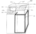
図1は、本発明を適用した現金自動取引装置の一実施例の外観を示す斜視図である。
【0011】
現金自動取引装置101は装置筐体101’で囲われており、その左部内部には、上部正面板101aに設けられたカードスロット102aと連通し利用者のカードを処理し、取引明細票を印字して放出するカード・明細票処理機構102と、取引の内容を表示および入力する顧客操作部105とを備えている。また、現金自動取引装置101の右部内部には、紙幣を処理する紙幣入出金機構1を備えており、上部の傾いた正面板101bに紙幣スロット20aが設けられている。
【0012】
また、紙幣入出金機構1の下部の紙幣収納部は、装置筐体101’とは別の数十mmの厚い鉄板で構成する金庫筐体106で囲まれている。装置筐体101’も堅固な筐体構造であるが、金庫筐体106はさらに堅固な構造で、セキュリティを高める。この現金自動取引装置101は、カード、紙幣、明細票を媒体とし、利用者の紙幣預入れ、支払、振込などの処理を行うことができる。
【0013】
図2は、現金自動取引装置101の一実施例の制御関係を示す制御ブロック図である。前述のように、現金自動取引装置101に納められたカード・明細票処理機構102、紙幣入出金機構1および顧客操作部105は、バス107aを介して本体制御部107と接続されており、本体制御部107の制御の下に必要な動作を行う。
【0014】
本体制御部107は、上記の他に、インタフェース部107b、係員操作部107c、外部記憶装置107dともバス107aを介して接続されており、必要なデータのやりとりを行うが、本発明の特徴には直接関係がないので詳細な説明は省略する。なお、図2に示した108は、上記各機構、構成部分に電力を供給する電源部である。
【0015】
図3は、図1の現金自動取引装置の中で、本発明に関わる紙幣入出金機構1の一実施例の構成を示す側面図である。
紙幣入出金機構1は、利用者が紙幣の投入・取り出しを行う入出金口20と、紙幣の判別を行う紙幣判別部30と、入金した紙幣を取引成立までの間一旦収納する一時保管庫40と、入金時取引が成立した紙幣を収納する1ヶの入金庫60と、出金用の紙幣を収納する1ヶの出金庫70と、入出金兼用の2ヶのリサイクル庫80と、リサイクル庫80に補充する紙幣や、リサイクル庫から回収した紙幣を収納する装填・回収庫81と、紙幣判別部30を通り、入出金口20、一時保管庫40、入金庫60、出金庫70、リサイクル庫80、装填・回収庫81に対し、紙幣を搬送する紙幣搬送路50と、図示せぬ制御部とから構成される。
【0016】
なお、上記例では、紙幣入出金口20は入金口と出金口を兼用した構成であるが、必ずしも一体とする必要はなく、利用者により投入された紙幣を装置内に繰り出す入金口と利用者に放出する紙幣を収納する出金口とを別々に設けてもよい。
【0017】
図4は、紙幣入出金機構1の一実施例の制御関係を説明するための制御ブロック図である。
同図に示すように、紙幣入出金機構1の制御部10は、現金自動取引装置101の本体制御部107とバス107aを介して接続され、本体制御部107からの指令および紙幣入出金機構1の状態検出に応じて紙幣入出金機構1の制御を行い、また、紙幣入出金機構1の状態を、必要に応じてバス107aを介して本体制御部107に送る。紙幣入出金機構1の中では、各ユニット(入出金口20、紙幣判別部30、一時保管庫40、紙幣搬送路50、入金庫60、出金庫70、リサイクル庫80、装填・回収庫81)の駆動モータや電磁ソレノイドやセンサ(図示せず)と接続され、取引に応じて、センサで状態を監視しながら、アクチュエータを駆動制御する。
【0018】
本紙幣入出金機構1は、図3に示すように、入出金口20、紙幣判別部30、一時保管庫40と、紙幣搬送路50から構成される上部紙幣機構1aと、入金庫60、出金庫70、リサイクル庫80、装填・回収庫81および、各収納庫の前面に配する搬送路90から構成される下部紙幣機構1bから構成される。
【0019】
さらに、下部紙幣機構1bは、約50mm程度の厚い鉄板で構成される金庫筐体(保護筐体)106の中に実装されており、上部紙幣機構1aの搬送路(上部搬送路)と下部紙幣機構1bの搬送路(下部搬送路)は、連結搬送路(搬送路接続手段)540によって接続されており、連結搬送路540を介して上部紙幣機構1aと下部紙幣機構1bとの間での紙幣の搬送を行う。
【0020】
さらに詳しくいうと、連結搬送路540は、下部紙幣機構1bを囲う金庫筐体(保護筐体)106の上面鉄板の上部紙幣機構1aの搬送路501iと下部紙幣機構1bの搬送路901aの連結する位置に設けられる。上面鉄板に開けられたスリットは、紙幣が通過するための長さと該スリットに搬送されてきた紙幣を挟持して繰り出すよう取り付けられたに搬送ローラの幅の大きさを有する。
【0021】
搬送路の駆動源(モータ)は、上部紙幣機構1aの搬送路(上部搬送路)と下部紙幣機構1bの搬送路(下部搬送路)とで別々に設けてもよいが、単一の駆動源を用い、駆動力を搬送路501i−540−901a間に設けられたギヤで伝達するようにしてもよい。
【0022】
また、紙幣搬送路50は、紙幣判別部30を双方向に通過し、矢印501a〜501hおよび901a〜901eに示す搬送路を経由して、入出金口20、一時保管庫40、入金庫60、出金庫70、リサイクル庫80、装填・回収庫81を相互に接続している。各矢印のうち片方向矢印は、紙幣がその矢印方向にのみ搬送する一方向紙幣搬送路であることを、両方向の矢印は、紙幣が取引動作毎に双方向のいずれかに切り替えて搬送する双方向搬送路であることを示している。
【0023】
さらに、紙幣搬送路50の各分岐点には、切替えゲート502,503および5ヶ所の902があって、各取引動作毎にそれぞれ記号a,bで示す位置に制御され、紙幣搬送方向を切り替えるようにしている。
以上の構成の紙幣入出金機構1により、利用者による入出金動作、係員による装填・回収動作を行う。
【0024】
まず、入金取引時の動作を説明する。
入金動作時、入出金口20に投入された紙幣は、一枚ずつに分離され、紙幣判別部30で、紙幣の金種、真偽が判定される。紙幣判別部30により判別された紙幣は、切替えゲート503を切り替えて、一時保管庫40に一旦収納される。
【0025】
紙幣判別部30の判定によって判別できなかった紙幣や、傾きを生じている紙幣や、紙幣同志の間隔が異常(例えば、重なっている紙幣)は、リジェクトされるべき紙幣(以下リジェクト紙幣)と判定される。リジェクト紙幣は、一時保管庫40には取り込まれず、切替えゲート503を切り替え、入出金口20に戻されて収納される。入出金口20に戻されたリジェクト紙幣は、利用者に返却される。
【0026】
取引が確定すると、一時保管庫40に一旦収納された紙幣は、収納時の順番と逆の順番で、一時保管のときとは逆方向に送出され、紙幣判別部30を通過する。そして、この判別部30を通過した紙幣は、切替えゲート502を502a方向に切り替え、入金庫60、リサイクル庫80、リジェクト庫90のいずれかの切替えゲート903が図示903b方向に切り替えられることにより、指定の収納庫に収納される。これにより、入金動作は終了する。
【0027】
次に、出金取引時の動作を説明する。
出金処理は、まず、出金庫70、リサイクル庫80の各金種毎の金庫から所定の枚数づつ紙幣が繰り出され、紙幣判別部30に供給される。紙幣判別部30では、金種を判別する。そして、切替えゲート503が紙幣を入出金口側に収納されるように切替えられ、紙幣判別部30を通過した紙幣は、入出金口20に収納され、その後スロット20a上面のシャッタを開いて利用者が紙幣を取ることができるようにする。利用者が入出金口20の収納部内にある紙幣を受取ることにより、出金処理は終了する。
【0028】
次に、紙幣をリサイクル庫80に装填したり、逆にリサイクル庫80内の紙幣を回収する動作について説明する。
装填と回収は、装填・回収庫81、一時保管庫40、リサイクル庫80との間で、紙幣を搬送することで実現できる。
【0029】
まず、装填動作は、装填・回収庫81に一括して紙幣をセットし、装置内で自動的にリサイクル庫80に収納する動作である。また、回収動作は、リサイクル庫80が満杯になった時などに、自動的にリサイクル庫80から所定枚数を装填・回収庫81に回収収納する動作である。回収は、装填動作と逆のルートで移動する動作となる。
以上が、紙幣入出金機構1の基本的な動作である。この紙幣入出金機構1は、図1に示すように、現金自動取引装置101の右側内部に実装される。
【0030】
次に、図5を用いて、紙幣入出金機構1の係員の操作性に関わる構成について説明する。本実施例に係る現金自動取引装置101は、装置前面から保守操作を行う構成(前面操作型)にすることも、後面から保守操作を行う構成(後面操作型)にすることも可能である。
【0031】
係員が前面から保守操作を行う場合(前面操作型)は、図5(a)に示すように、装置前面から、図示せぬロック機構を解除し、傾いた正面板101bを図のように上に持ち上げて開状態にした後、紙幣入出金機構1の上部紙幣機構1aをスライドレール機構151に沿って前方に引き出し、必要な保守操作を行う。
【0032】
さらに、図示せぬロック機構を解除し装置前扉101cを開状態にし、金庫筐体106の前面扉106aを、図示せぬロックを解除して、開状態にした後、紙幣入出金機構1の下部紙幣機構1bをスライドレール機構152に沿って前方に引出し、必要な保守操作を行う。
【0033】
また、同様に現金自動取引装置101で、係員が後面から保守操作を行う場合(後面操作型)は、図5(b)に示すように、装置後面から、図示せぬロック機構を解除し、装置の後扉101dを開状態にする。次に、図5(c)に示すように、紙幣入出金機構1の上部紙幣機構1aをスライドレール機構151に沿って後方に引き出し、必要な保守操作を行う。
【0034】
さらに、金庫筐体106の後面扉106bを、図示せぬロックを解除して、開状態にし、下部紙幣機構1bをスライドレール機構152に沿って後方に引き出し、必要な保守操作を行う。
以上のように、本実施例における紙幣入出金機構1は、装置前面から操作する形態(前面操作型)にすることも、後面からでも保守操作する形態(後面操作型)にすることもできる。
【0035】
図6は、本発明に係る連結搬送路(搬送路接続手段)540の具体的な実施形態を示す図であり、引出されている上部紙幣機構1aを基準位置に戻す場合の動作を示している。同図(a)〜(c)は、保守操作などのために引出された上部紙幣機構1aを後方から矢印601方向にスライドさせて基準位置610に戻す時の状態を説明するための図である。
【0036】
ここで、図8を用いて、まず連結搬送路(搬送路接続手段)540と上部紙幣機構1aの連結部の構造を説明しておく。
同図に示すように、上部紙幣機構1aの連結部分には、上部紙幣機構1aにおける搬送路の左右に設けられる搬送ガイド605の端部がくし型形状に形成されるとともに、第1の突起片602がネジなどで取り付けられている。第1の突起片602の取り付け位置は、上部紙幣機構1aを装置後方に引出すか装置前方に引出すかによって変えられる。前者の場合は図8の実線で示した位置に、後者の場合は同図破線で示した位置に変えられる。
【0037】
一方、連結搬送路(搬送路接続手段)540には、前記左右のくし型形状の搬送ガイド605のそれぞれに噛み合うようなくし型形状の開閉ガイドA603a,開閉ガイドB603bが設けられる。開閉ガイドA603aと開閉ガイドB603bは、軸を中心に回動可能となっており、通常時はバネなどの力で開状態になる方向に付勢されている。
【0038】
また、一方の開閉ガイドA603aには、前記第1の突起片602に当接する位置に第2の突起片6071が設けられている。第2の突起片6071は、上部紙幣機構1aを一方向(例えば装置後方)から挿入する場合に前記第1の突起片602に押され、開閉ガイド603aを軸の回りを反時計方向に回動させる。また、他方の開閉ガイドA603bには、上部紙幣機構1aを他方向(例えば装置前方)から挿入する場合のために、先に述べたように破線の位置に変えられた第1の突起片602に当接する位置に同図破線で示す第2の突起片6072が設けられている。第2の突起片6072は、上部紙幣機構1aを逆の方向(例えば装置前方)から挿入した場合に前記第1の突起片602に押され、開閉ガイド603aを軸の回りを時計方向に回動させる。
【0039】
なお、図8では省略しているが、開閉ガイドA603aと開閉ガイドB603bはバネなどの力により通常は開状態になるように付勢されている。また、必ずしも必須ではないが、開閉ガイドA603aと開閉ガイドB603bはギア(図6の606参照)で連結されていて連動して開閉するように構成されている。
【0040】
次に、図6に戻って、引出されている上部紙幣機構1aを基準位置に戻す場合の動作を説明する。図7(a)〜(c)は、図6(a)〜(c)における第1の突起片602、第2の突起片6071、開閉ガイドA603a、開閉ガイドB603bの動作状態のをわかりやすくするために拡大して示した図である。
【0041】
図6(a)および図7(a)は、後方に引き出されている上部紙幣機構1aを後方から押し込むときの状態を示している(後面操作型)。この場合、上部紙幣機構1aに設けられた第1の突起片602が開閉ガイドA603aの第2の突起片6071を押し込むことにより、開閉ガイドA603aは矢印604a方向に回動される(図6(b)/図7(b)参照)。先に述べたように、開閉ガイドA603aは、ギア606を通じて開閉ガイドB603bに連動しているため、矢印604b方向に回動される(図6(b)/図7(b)参照)。
【0042】
上部紙幣機構1aをさらに押し込むことにより、開閉ガイドA603aは閉じられ、上部紙幣機構1a内の右側の搬送ガイド605に連結される。上記動作によって、開閉ガイドA603aにギア606で連動されている開閉ガイドB603bも同時に上部紙幣機構1aの左側の搬送ガイド605に連結される。図6(c)および図7(c)は、開閉ガイドA603aおよび開閉ガイドB603bが、左右の搬送ガイド605に連結された状態を示している。
【0043】
図6(d)〜(f)は、後方ではなく前方に引き出されている上部紙幣機構1aを前方から押し込むときの状態を示している(前面操作型)。図6(d)〜(f)の動作状態は、押し込む方向が反対であること以外は、図6(a)〜(c)の動作状態に対応しているので説明は省略する。なお、この場合は、第1の突起片602の取り付け位置を前記図6(a)〜(c)の場合の取り付け位置から変える必要がある。また、この場合は、開閉ガイドB603bに取り付けられている第2の突起片6072が使用されることは図に示すとおりである。
【0044】
上記実施例では、上部紙幣機構1aを基準位置610までに押し込む動作を説明したが、連結搬送路(搬送路接続手段)540の下側面にも同様にバネ力などで開くように付勢されている一対の開閉可能な開閉ガイドが設けられており、下部紙幣機構1bを基準位置610まで押し込む動作も同様に行われる。
【0045】
さらに、基準位置610まで押し込まれて収納されている上部紙幣機構1aまたは下部紙幣機構1bを、装置外部に引き出す場合は、「図6(c)または図7(c)」→「図6(b)または図7(b)」→「図6(a)または図7(a)」、あるいは図6(f)→図6(e)→図6(d)の逆順の状態をたどって引き出される。
【0046】
以上のことから明らかなように、上部紙幣機構1aまたは下部紙幣機構1bを装置外部(装置前方または装置後方)に引き出す場合、開閉ガイドA603aおよび開閉ガイドB603bはバネ力などにより開くように付勢されているので、引き出す動作に伴って徐々に開くため、紙幣がジャムなどで連結搬送路(搬送路接続手段)540付近に紙幣が残留している場合であっても、その紙幣を破いたり、開閉ガイドA603aや開閉ガイドB603bを破損したりすることがなくなる。
【0047】
なお、上記実施例では、開閉ガイドA603aおよび開閉ガイドB603bの両方が設けられ、ユニットを引出す時にこれらのガイドが両方とも開状態になる例を示したが、本発明は、上記構成に限らず、単一のガイドを用いたものでも有効である。
【0048】
【発明の効果】
本発明によれば、分割した紙幣搬送手段を接続する搬送路接続手段付近において、紙幣のジャムなどの障害発生し、保守のために前記分割した搬送手段を装置の外へ引き出す場合において、当該媒体が破損したり、もしくは前記搬送路接続手段の構成要素であるガイドが破損するのを防止できる。
【図面の簡単な説明】
【図1】本発明を適用した現金自動取引装置の一実施例の外観を示す斜視図である。
【図2】現金自動取引装置の制御関係の一実施例を示す制御ブロック図である。
【図3】本発明に関わる紙幣入出金機構の一実施例の構成を示す側面図である。
【図4】紙幣入出金機構の一実施例の制御関係を説明するための制御ブロック図である。
【図5】紙幣入出金機構の係員の操作性に関わる構成を説明するための図である。
【図6】本発明に係る連結搬送路(搬送路接続手段)の具体的な実施形態を示す図である。
【図7】図6(a)〜(c)における第1の突起片、第2の突起片、開閉ガイドA、開閉ガイドBの動作状態のをわかりやすくするために拡大して示した図である。
【図8】連結搬送路(搬送路接続手段)と上部紙幣機構の連結部の構造を説明するための図である。
【符号の説明】
1:紙幣入出金機構、1a:上部紙幣機構、1b:下部紙幣機構、10:制御部、20:入出金口、20a:紙幣スロット、30:紙幣判別部、40:一時保管庫、50:紙幣搬送路、60:入金庫、70:出金庫、80:リサイクル庫、81:装填・回収庫、90:開閉搬送路、101:現金自動取引装置、101’:装置筐体、101a:上面正面板、101b:正面板、101c:装置前扉、101d:装置後扉、102:カード・明細票処理機構、102a:カードスロット、105:顧客操作部、106:金庫筐体、106a:前面扉、106b:後面扉、107:本体制御部、107a:バス、107b:インタフェース部、107c:係員操作部、107d:外部記憶装置、108:電源、151,152:スライドレール機構、501a〜501h,901a〜901e:紙幣搬送路、502,503,902a〜902e:切替えゲート、540:搬送路接続手段(連結搬送路)、601,604a,604b:矢印、602:第1の突起片、603a:開閉ガイドA、603b:開閉ガイドB、605:搬送ガイド、606:ギア、6071,6072:第2の突起片、610:基準位置。[0001]
BACKGROUND OF THE INVENTION
The present invention relates to a banknote handling apparatus that handles banknotes, and in particular, when pulling out a unit including one of the divided transporting means, the remaining banknotes are damaged or the guides that are components of the transporting path connecting means are damaged. It is related with the banknote handling apparatus which can be prevented.
[0002]
[Prior art]
In a conventional banknote handling apparatus, for example, an automatic cash handling apparatus, banknotes for transactions to be stored inside the apparatus have to be stored in a casing having a reinforced structure such as a safe for security reasons. The most common means is that all the banknote handling mechanisms including the banknote storage unit and the banknote handling unit for depositing or withdrawing banknotes from the customer are installed in the safe. The banknotes are deposited and received through the opening provided in.
[0003]
On the other hand, there is also means for dividing the banknote handling mechanism into the banknote processing section and banknote storage section, and providing the banknote storage section in the protective housing. For example, in the example described in Japanese Patent Laid-Open No. 2000-172946, the bill depositing / dispensing machine is divided into upper and lower parts, and the lower unit is mounted in a safe housing, thereby enhancing the security of the bill storage.
[0004]
[Problems to be solved by the invention]
However, in the banknote handling apparatus provided with the banknote handling mechanism divided into the inside and outside of the protective housing and provided with the transport path connection means for connecting the divided transport means to each other, the banknote remains in the vicinity of the transport path connection means. In this case, when the unit including one of the divided banknote transporting means is pulled out to remove the banknote, the banknote may be damaged or the banknote guide which is a component of the transport path connecting means may be damaged. It was.
[0005]
An object of the present invention is to enable a banknote handling device capable of preventing a banknote from being damaged or a guide which is a component of a transport path connecting means from being damaged when a unit including one of the divided transporting means is pulled out. Is to provide.
[0006]
[Means for Solving the Problems]
In order to achieve the above object, the present invention divides the banknote transport means into a protective housing (safe box) and outside of the protective housing, and between the divided banknote transport means and the other banknote transport means. In the banknote handling apparatus provided with the transport path connection means (540) and pulling out the unit including one banknote transport means in a direction perpendicular to the banknote transport direction, the transport path connection means (540) has a guide that can be opened and closed. A first projection piece (602) is provided on the drawing unit (upper bill mechanism 1a or
[0007]
The guides (opening and
[0008]
Also, depending on whether the drawing direction is forward or backward with respect to the apparatus, the first projection piece (602) is provided at each position and the pair of guides (opening /
[0009]
By adopting such a configuration, it becomes possible to prevent the banknotes remaining in the vicinity of the transport path connecting means (540) and the breakage of the open / close guide.
[0010]
DETAILED DESCRIPTION OF THE INVENTION
Hereinafter, an embodiment of the present invention will be described in detail with reference to the drawings.
FIG. 1 is a perspective view showing an appearance of an embodiment of an automatic teller machine to which the present invention is applied.
[0011]
The
[0012]
Moreover, the bill storage part at the bottom of the bill depositing /
[0013]
FIG. 2 is a control block diagram showing the control relationship of one embodiment of the
[0014]
In addition to the above, the main
[0015]
FIG. 3 is a side view showing the configuration of an embodiment of the banknote depositing / withdrawing
The banknote deposit /
[0016]
In the above example, the banknote deposit /
[0017]
FIG. 4 is a control block diagram for explaining the control relationship of one embodiment of the banknote deposit /
As shown in the figure, the control unit 10 of the banknote deposit /
[0018]
As shown in FIG. 3, the banknote deposit /
[0019]
Further, the
[0020]
More specifically, the
[0021]
The drive source (motor) for the transport path may be provided separately for the transport path (upper transport path) of the upper banknote mechanism 1a and the transport path (lower transport path) of the
[0022]
Moreover, the
[0023]
Furthermore, at each branch point of the
With the banknote depositing / withdrawing
[0024]
First, the operation at the time of deposit transaction will be described.
During the depositing operation, the bills inserted into the deposit /
[0025]
A banknote that cannot be determined by the determination of the
[0026]
When the transaction is confirmed, the banknotes once stored in the
[0027]
Next, the operation at the time of a withdrawal transaction will be described.
In the withdrawal process, first, a predetermined number of banknotes are fed out from the safes for each denomination of the withdrawal bank 70 and the
[0028]
Next, the operation of loading banknotes into the
Loading and recovery can be realized by transporting banknotes between the loading /
[0029]
First, the loading operation is an operation in which banknotes are collectively set in the loading /
The above is the basic operation of the bill deposit /
[0030]
Next, the structure regarding the operativity of the attendant of the banknote depositing / withdrawing
[0031]
When the clerk performs maintenance operations from the front (front operation type), as shown in FIG. 5A, the lock mechanism (not shown) is released from the front of the device and the tilted
[0032]
Further, the lock mechanism (not shown) is released and the
[0033]
Similarly, in the
[0034]
Further, the
As described above, the banknote depositing /
[0035]
FIG. 6 is a view showing a specific embodiment of the coupled transport path (transport path connecting means) 540 according to the present invention, and shows the operation when returning the drawn upper banknote mechanism 1a to the reference position. . (A)-(c) is a figure for demonstrating the state at the time of sliding the upper banknote mechanism 1a pulled out for maintenance operation etc. from the back to the
[0036]
Here, the structure of the connection part of the connection conveyance path (conveyance path connection means) 540 and the upper banknote mechanism 1a is demonstrated using FIG.
As shown in the figure, at the connection portion of the upper banknote mechanism 1a, the ends of the conveyance guides 605 provided on the left and right of the conveyance path in the upper banknote mechanism 1a are formed in a comb shape, and the first
[0037]
On the other hand, the connection conveyance path (conveyance path connecting means) 540 is provided with comb-shaped opening / closing guides A603a and B603b so as to mesh with the left and right comb-shaped conveyance guides 605, respectively. The opening /
[0038]
One opening /
[0039]
Although not shown in FIG. 8, the opening /
[0040]
Next, returning to FIG. 6, the operation in the case of returning the drawn upper banknote mechanism 1a to the reference position will be described. 7A to 7C make it easy to understand the operation states of the
[0041]
FIG. 6A and FIG. 7A show a state when the upper banknote mechanism 1a drawn backward is pushed from the rear (rear operation type). In this case, the
[0042]
By further pushing the upper banknote mechanism 1a, the opening / closing guide A603a is closed and connected to the
[0043]
FIGS. 6D to 6F show a state when the upper banknote mechanism 1a that is drawn forward rather than backward is pushed from the front (front operation type). The operation states of FIGS. 6 (d) to 6 (f) correspond to the operation states of FIGS. 6 (a) to 6 (c) except that the pushing direction is opposite, and the description thereof will be omitted. In this case, it is necessary to change the mounting position of the first projecting
[0044]
In the above embodiment, the operation of pushing the upper banknote mechanism 1a to the
[0045]
Further, when the upper banknote mechanism 1a or the
[0046]
As is clear from the above, when the upper bill mechanism 1a or the
[0047]
In the above embodiment, both the opening /
[0048]
【The invention's effect】
According to the present invention, when a failure such as a banknote jam occurs in the vicinity of the conveyance path connecting means for connecting the divided bill conveyance means, and the divided conveyance means is pulled out of the apparatus for maintenance, the medium Can be prevented from being damaged, or the guide as a component of the transport path connecting means can be prevented from being damaged.
[Brief description of the drawings]
FIG. 1 is a perspective view showing an appearance of an embodiment of an automatic teller machine to which the present invention is applied.
FIG. 2 is a control block diagram showing an embodiment of the control relationship of the automatic teller machine.
FIG. 3 is a side view showing a configuration of an embodiment of a banknote depositing / withdrawing mechanism according to the present invention.
FIG. 4 is a control block diagram for explaining the control relationship of an embodiment of a bill depositing / withdrawing mechanism.
FIG. 5 is a diagram for explaining a configuration related to the operability of the staff of the banknote deposit and withdrawal mechanism.
FIG. 6 is a diagram showing a specific embodiment of a connected transport path (transport path connecting means) according to the present invention.
7 is an enlarged view for easy understanding of the operation state of the first protrusion piece, the second protrusion piece, the open / close guide A, and the open / close guide B in FIGS. 6 (a) to 6 (c). FIG. is there.
FIG. 8 is a view for explaining the structure of a connecting portion between a connecting transport path (transport path connecting means) and an upper bill mechanism.
[Explanation of symbols]
1: Banknote deposit / withdrawal mechanism, 1a: Upper bill mechanism, 1b: Lower bill mechanism, 10: Control unit, 20: Deposit / withdrawal port, 20a: Bill slot, 30: Bill discriminating unit, 40: Temporary storage, 50: Bill Transport path, 60: Safe deposit box, 70: Safe deposit box, 80: Recycle box, 81: Loading / collecting box, 90: Opening / closing transport path, 101: Automatic cash transaction device, 101 ': Device casing, 101a: Front face plate , 101b: Front plate, 101c: Front door of the apparatus, 101d: Rear door of the apparatus, 102: Card / detail slip processing mechanism, 102a: Card slot, 105: Customer operation unit, 106: Safe case, 106a: Front door, 106b : Rear door 107: main body control unit 107a: bus 107b: interface unit 107c: clerk operation unit 107d: external storage device 108: power supply 151, 152: slide rail mechanism , 501a to 501h, 901a to 901e: bill transport path, 502, 503, 902a to 902e: switching gate, 540: transport path connection means (connected transport path), 601, 604a, 604b: arrow, 602: first protrusion Piece, 603a: Open / close guide A, 603b: Open / close guide B, 605: Conveyance guide, 606: Gear, 6071, 6072: Second protrusion piece, 610: Reference position.
Claims (15)
紙幣を入金または出金する開口を有する第1のユニットと、
紙幣を収納する紙幣収納庫を有する第2のユニットと、
前記開口と前記紙幣収納庫との間で紙幣を搬送する紙幣搬送機構とを備え、
前記第1のユニットおよび前記第2のユニットの少なくとも一つは着脱可能なユニットであり、
前記紙幣搬送機構は、
前記着脱可能なユニット内部に設けられた搬送ガイドを有する第1の搬送機構と、
前記着脱可能なユニットの移動に連動して、前記第1の搬送機構との連結を脱着する連結搬送機構とを備え、
前記第1の搬送機構は、第1の突起部を有し、
前記連結搬送機構は、前記第1の搬送機構の搬送ガイドと噛合して紙幣を案内する開閉可能な開閉ガイドを有し、
前記開閉ガイドは、前記第1の突起部と当接する位置に第2の突起部を有し、
前記着脱可能なユニットが装着される場合に、前記第1の突起部が前記第2の突起部を押動することにより前記第1の搬送機構と連結することを特徴とする紙幣取扱装置。A banknote handling apparatus that executes at least one of banknote depositing and withdrawal processing,
A first unit having an opening for depositing or withdrawing banknotes;
A second unit having a banknote storage for storing banknotes;
A banknote transport mechanism for transporting banknotes between the opening and the banknote storage;
At least one of the first unit and the second unit is a detachable unit,
The bill transport mechanism is
A first transport mechanism having a transport guide provided inside the detachable unit;
In conjunction with the movement of the detachable unit, a connection transport mechanism for detaching the connection with the first transport mechanism ,
The first transport mechanism has a first protrusion,
The connection transport mechanism has an openable open / close guide that meshes with a transport guide of the first transport mechanism to guide a bill.
The open / close guide has a second protrusion at a position in contact with the first protrusion,
When said detachable unit is mounted, the first protrusion banknote handling apparatus characterized that you connected to the first conveyance mechanism by pressing the second projecting portion.
前記第1の突起部は、前記着脱可能なユニットに設け、
前記第2の突起部は、前記開閉ガイドの端部外側に設け、
前記着脱可能なユニットは、前記第2の突起部の側から着脱されることを特徴とする紙幣取扱装置。The bill handling apparatus according to claim 1 ,
The first protrusion is provided on the detachable unit,
The second protrusion is provided outside the end of the opening / closing guide,
The banknote handling apparatus, wherein the detachable unit is detachable from the side of the second protrusion.
前記第1のユニットおよび前記第2のユニットの少なくとも一つは複数の方向に着脱可能なユニットであり、At least one of the first unit and the second unit is a unit detachable in a plurality of directions,
前記第1の突起部及び第2の突起部は、前記ユニットの着脱方向に応じて配置されることを特徴とする紙幣取扱装置。The banknote handling apparatus, wherein the first projecting portion and the second projecting portion are arranged in accordance with an attaching / detaching direction of the unit.
紙幣を入金または出金する開口と紙幣を搬送する搬送路とを有する第1のユニットと、
紙幣を収納する紙幣収納庫と紙幣を搬送する搬送路とを有する第2のユニットと、
前記第1および第2のユニットのうち少なくとも一つのユニットをスライドするスライド機構と、
前記第1のユニットの搬送路と前記第2のユニットの搬送路とに連結する連結搬送機構とを備え、
前記連結搬送機構は、スライドされるユニットが装着される場合にスライドされるユニットが有する紙幣搬送路の搬送ガイドと噛合し、前記スライドされるユニットが脱着する場合に前記紙幣搬送路の搬送ガイドとの噛合を開放する開閉ガイドを有することを特徴とする紙幣取扱装置。A banknote handling apparatus that executes at least one of banknote depositing and withdrawal processing,
A first unit having an opening for depositing or withdrawing banknotes and a transport path for transporting banknotes;
A second unit having a banknote storage for storing banknotes and a transport path for transporting banknotes;
A slide mechanism for sliding at least one of the first and second units;
A connection transport mechanism connected to the transport path of the first unit and the transport path of the second unit;
The connection conveying mechanism conveys guide and meshed paper money transport path unit has to be slid when the unit to be slide is mounted, a conveyance guide of the paper money transport path when the unit is the slide desorbs A bill handling apparatus having an opening / closing guide for releasing the engagement of the bill.
紙幣を入金または出金する開口と紙幣を搬送する紙幣搬送路とを有する第1のユニットと、
紙幣を収納する紙幣収納庫と紙幣を搬送する紙幣搬送路とを有する第2のユニットと、
前記第1および第2のユニットのうち少なくとも一つのユニットをスライドするスライド機構と、
前記第1のユニットの紙幣搬送路と前記第2のユニットの紙幣搬送路とに連結する連結搬送機構とを備え、
前記連結搬送機構は、前記スライド機構による前記第1および第2のユニットの少なくとも一方のユニットのスライドに応じて開閉が制御される開閉ガイドとを備えることを特徴とする紙幣取扱装置。A banknote handling apparatus that executes at least one of banknote depositing and withdrawal processing,
A first unit having an opening for depositing or withdrawing banknotes and a banknote transport path for transporting banknotes;
A second unit having a banknote storage for storing banknotes and a banknote transport path for transporting banknotes;
A slide mechanism for sliding at least one of the first and second units;
A connection transport mechanism connected to the banknote transport path of the first unit and the banknote transport path of the second unit;
The banknote handling apparatus, wherein the connection transport mechanism includes an opening / closing guide that is controlled to open and close in accordance with sliding of at least one of the first and second units by the slide mechanism.
前記第2のユニットを囲む保護筐体をさらに備え、
前記連結搬送機構は、前記保護筐体に設けられていることを特徴とする紙幣取扱装置。It is a banknote handling apparatus in any one of Claim 1 to 5,
A protective housing surrounding the second unit;
The banknote handling apparatus, wherein the connection transport mechanism is provided in the protective housing.
紙幣の入金口と入金された紙幣を搬送する上部紙幣搬送路を有する上部ユニットと、
前記入金口に入金された紙幣を収納する紙幣収納庫と当該紙幣収納庫に収納する紙幣を搬送する下部紙幣搬送路を有する下部ユニットと、
前記上部紙幣搬送路と前記下部紙幣搬送路とを連結する搬送路接続機構と、
前記上部ユニットまたは下部ユニットの少なくとも一つのユニットをスライドするスライド機構とを備え、
前記搬送路接続機構は、スライドされるユニットが装着される場合にスライドされるユニットが有する紙幣搬送路の搬送ガイドと噛合し、前記スライドされるユニットが脱着する場合に前記紙幣搬送路の搬送ガイドとの噛合を開放する開閉ガイドを有することを特徴とする紙幣取扱装置。A banknote handling apparatus for handling banknotes,
An upper unit having a banknote deposit port and an upper banknote transport path for transporting the banknotes deposited;
A lower units having a lower bill transport path for transporting a banknote to be stored in the bill storage and the banknote storage box for storing bills which are deposited into the deposit port,
A transport path connection mechanism that connects the upper banknote transport path and the lower banknote transport path;
A slide mechanism for sliding at least one of the upper unit and the lower unit,
The conveyance path connection mechanism conveys guide and meshed paper money transport path unit has to be slid when the unit to be slide is mounted, conveyance guide of the paper money transport path when the unit is the slide desorbs A bill handling device having an opening and closing guide for releasing the engagement with the bill.
前記開閉ガイドの噛合は、前記スライドされるユニットの動きに連動して制御されることを特徴とする紙幣取扱装置。The banknote handling apparatus according to claim 4 or 7,
The bill handling apparatus is characterized in that the engagement of the opening / closing guide is controlled in conjunction with the movement of the sliding unit.
紙幣の入金口と入金された紙幣を搬送する上部紙幣搬送路とを有する上部ユニットと、
前記入金口に入金された紙幣を収納する紙幣収納庫と当該紙幣収納庫に収納される紙幣を搬送する下部紙幣搬送路を有する下部ユニットと、
前記上部ユニットおよび前記下部ユニットの少なくとも一方のユニットをスライド可能なスライド機構と、
スライド可能なユニットの前記上部紙幣搬送路あるいは前記下部紙幣搬送路に設けられた搬送ガイドと、
前記上部紙幣搬送路と前記下部紙幣搬送路とを連結する搬送路接続機構とを備え、
該搬送路接続機構は、前記スライド機構による前記上部ユニットおよび前記下部ユニットの少なくとも一方のユニットのスライドに応じて前記搬送ガイドと噛合しあるいは開放される開閉ガイドを有することを特徴とする紙幣取扱装置。A banknote handling apparatus for processing banknotes,
An upper unit having a banknote deposit port and an upper banknote transport path for transporting the banknotes deposited;
A lower unit having a banknote storage for storing banknotes deposited in the deposit port and a lower banknote transport path for transporting banknotes stored in the banknote storage;
A slide mechanism capable of sliding at least one of the upper unit and the lower unit;
A conveyance guide provided in the upper bill conveyance path or the lower bill conveyance path of the slidable unit;
A transport path connection mechanism that connects the upper banknote transport path and the lower banknote transport path ;
The transport path connection mechanism has an opening / closing guide that is engaged with or released from the transport guide according to the slide of at least one of the upper unit and the lower unit by the slide mechanism. .
前記下部ユニットを囲む保護筐体をさらに備え、
前記搬送路接続機構は、前記保護筐体に設けられていることを特徴とする紙幣取扱装置。The bill handling apparatus according to claim 7 or 9, wherein
A protective housing surrounding the lower unit;
The banknote handling apparatus, wherein the transport path connection mechanism is provided in the protective housing.
前記スライドされるユニットの前記紙幣搬送路は、第1の突起部を有し、
前記開閉ガイドは、前記開閉ガイドの前記第1の突起部が当接する位置に第2の突起部を有し、
前記スライドされるユニットが装着される場合に、前記第1の突起部が前記第2の突起部を押動することにより、前記紙幣搬送路の搬送ガイドと前記開閉ガイドとが噛合することを特徴とする紙幣取扱装置。A bill handling device according to any one of claims 4, 5 or 7 to 10,
The bill conveyance path of the unit to be slid has a first protrusion,
The open / close guide has a second protrusion at a position where the first protrusion of the open / close guide contacts,
When the unit to be slid is mounted, the first protrusion pushes the second protrusion, so that the conveyance guide of the banknote conveyance path and the opening / closing guide mesh with each other. A bill handling device.
前記開閉ガイドは、連結部材により相互に連結された第1および第2のガイドを含み、前記第1および第2のガイドの少なくとも一方の端部外側に向かって前記第2の突起部が設けられていることを特徴とする紙幣取扱装置。It is a banknote handling apparatus in any one of Claim 1 to 11 ,
The open / close guide includes first and second guides connected to each other by a connecting member, and the second protrusion is provided toward the outer side of at least one end of the first and second guides. The banknote handling apparatus characterized by the above-mentioned.
前記開閉ガイドは、連結部材により相互に連結された第1および第2のガイドを有し、
前記第1のガイドは、前記第2のガイドよりも長いことを特徴とする紙幣取扱装置。It is a banknote handling apparatus in any one of Claim 1 to 11,
The open / close guide has first and second guides connected to each other by a connecting member,
The banknote handling apparatus, wherein the first guide is longer than the second guide.
前記開閉ガイドは、弾性部材により開状態になるよう付勢されている第1および第2のガイドを有することを特徴とする紙幣取扱装置。It is a banknote handling apparatus in any one of Claim 1 to 11,
The banknote handling apparatus, wherein the opening / closing guide includes first and second guides biased to be opened by an elastic member.
前記搬送ガイドおよび前記開閉ガイドは互いに噛合可能なくし型形状部分を有していることを特徴とする紙幣取扱装置。The banknote handling apparatus, wherein the conveyance guide and the opening / closing guide have a die-shaped portion that can mesh with each other.
Priority Applications (6)
| Application Number | Priority Date | Filing Date | Title |
|---|---|---|---|
| JP2000358077A JP3916035B2 (en) | 2000-11-24 | 2000-11-24 | Banknote handling equipment |
| TW090127333A TW505902B (en) | 2000-11-24 | 2001-11-02 | Bill handling machine |
| US09/988,800 US6695307B2 (en) | 2000-11-24 | 2001-11-20 | Bill handling machine |
| EP01127961A EP1209633B1 (en) | 2000-11-24 | 2001-11-23 | Bill handling machine |
| KR10-2001-0073363A KR100417268B1 (en) | 2000-11-24 | 2001-11-23 | Bill handling machine |
| DE60130861T DE60130861T2 (en) | 2000-11-24 | 2001-11-23 | Banknote processing device |
Applications Claiming Priority (1)
| Application Number | Priority Date | Filing Date | Title |
|---|---|---|---|
| JP2000358077A JP3916035B2 (en) | 2000-11-24 | 2000-11-24 | Banknote handling equipment |
Publications (3)
| Publication Number | Publication Date |
|---|---|
| JP2002163704A JP2002163704A (en) | 2002-06-07 |
| JP2002163704A5 JP2002163704A5 (en) | 2004-11-11 |
| JP3916035B2 true JP3916035B2 (en) | 2007-05-16 |
Family
ID=18830043
Family Applications (1)
| Application Number | Title | Priority Date | Filing Date |
|---|---|---|---|
| JP2000358077A Expired - Fee Related JP3916035B2 (en) | 2000-11-24 | 2000-11-24 | Banknote handling equipment |
Country Status (6)
| Country | Link |
|---|---|
| US (1) | US6695307B2 (en) |
| EP (1) | EP1209633B1 (en) |
| JP (1) | JP3916035B2 (en) |
| KR (1) | KR100417268B1 (en) |
| DE (1) | DE60130861T2 (en) |
| TW (1) | TW505902B (en) |
Families Citing this family (45)
| Publication number | Priority date | Publication date | Assignee | Title |
|---|---|---|---|---|
| CA2680866C (en) * | 2002-10-18 | 2011-04-12 | Diebold, Incorporated | Automated banking machine which dispenses, receives and stores notes and other financial instrument sheets |
| ITMI20030454A1 (en) * | 2003-03-11 | 2004-09-12 | Razzaboni Cima Spa | MACHINE FOR ORDERED STORAGE AND BANKNOTE ISSUE. |
| JP2006209603A (en) * | 2005-01-31 | 2006-08-10 | Hitachi Omron Terminal Solutions Corp | Paper sheet handling device |
| US7322517B1 (en) * | 2005-06-03 | 2008-01-29 | Diebold Self-Service Systems Division Of Diebold, Incorporated | Enclosure for automated banking machine |
| US7367493B1 (en) * | 2005-06-03 | 2008-05-06 | Diebold Self-Serice Systems Division Of Diebold, Incorporated | Enclosure for automated banking machine |
| JP4730946B2 (en) * | 2005-06-17 | 2011-07-20 | 株式会社ユニバーサルエンターテインメント | Banknote processing apparatus and control system for banknote processing apparatus |
| JP2007034602A (en) * | 2005-07-26 | 2007-02-08 | Hitachi Omron Terminal Solutions Corp | Paper sheet discrimination device |
| JP4942330B2 (en) * | 2005-11-21 | 2012-05-30 | 日立オムロンターミナルソリューションズ株式会社 | Paper sheet handling equipment |
| US8662490B2 (en) * | 2006-09-05 | 2014-03-04 | Mei, Inc. | Bulk document feeder with removable cartridge |
| JP4368888B2 (en) * | 2006-12-15 | 2009-11-18 | 日立オムロンターミナルソリューションズ株式会社 | Paper sheet storage and paper sheet handling device |
| GB0702191D0 (en) * | 2007-02-05 | 2007-03-14 | Innovative Technology Ltd | Improvements Relating to Banknote Validation |
| EP2015259A1 (en) * | 2007-07-12 | 2009-01-14 | MEI, Inc. | Banknote handling apparatus |
| JP5220385B2 (en) * | 2007-11-02 | 2013-06-26 | 日立オムロンターミナルソリューションズ株式会社 | Banknote deposit and withdrawal mechanism and automatic cash transaction equipment |
| DE102007060803A1 (en) * | 2007-12-18 | 2009-06-25 | Wincor Nixdorf International Gmbh | Apparatus and method for storing banknotes |
| JP5122325B2 (en) * | 2008-02-26 | 2013-01-16 | 日立オムロンターミナルソリューションズ株式会社 | Paper sheet transport mechanism and paper sheet handling device |
| US8025214B1 (en) | 2008-07-31 | 2011-09-27 | Bank Of America Corporation | Cash handling device having integrated controller |
| JP5156532B2 (en) * | 2008-08-06 | 2013-03-06 | 日立オムロンターミナルソリューションズ株式会社 | Banknote handling equipment |
| US8181856B1 (en) | 2008-11-25 | 2012-05-22 | Bank Of America Corporation | Cash handling device having alert system |
| JP5268667B2 (en) | 2009-01-16 | 2013-08-21 | ローレル機械株式会社 | Banknote handling machine |
| JP5205292B2 (en) * | 2009-01-16 | 2013-06-05 | ローレル機械株式会社 | Banknote handling machine |
| DE102009038175A1 (en) | 2009-08-20 | 2011-02-24 | Wincor Nixdorf International Gmbh | Device and method for handling notes of value |
| JP5216805B2 (en) * | 2010-04-30 | 2013-06-19 | 日立オムロンターミナルソリューションズ株式会社 | Paper sheet processing equipment |
| JP5633451B2 (en) * | 2011-03-29 | 2014-12-03 | 沖電気工業株式会社 | Banknote handling device and delivery unit used for the banknote handling device |
| TWI456529B (en) * | 2011-07-26 | 2014-10-11 | 日立歐姆龍金融系統有限公司 | Paper sheet processing device |
| JP5845996B2 (en) * | 2012-03-26 | 2016-01-20 | 沖電気工業株式会社 | Media processing device |
| JP5511109B2 (en) * | 2013-03-04 | 2014-06-04 | 日立オムロンターミナルソリューションズ株式会社 | Paper sheet processing equipment |
| JP6146080B2 (en) * | 2013-03-26 | 2017-06-14 | セイコーエプソン株式会社 | Recording device |
| JP6291948B2 (en) * | 2014-03-25 | 2018-03-14 | 沖電気工業株式会社 | Banknote handling equipment |
| JP6216685B2 (en) * | 2014-05-30 | 2017-10-18 | 日立オムロンターミナルソリューションズ株式会社 | Banknote handling equipment |
| JP2016099677A (en) * | 2014-11-18 | 2016-05-30 | グローリー株式会社 | Banknote handling device |
| KR101719765B1 (en) * | 2015-02-13 | 2017-04-04 | 노틸러스효성 주식회사 | Automatic teller machine and gate apparatus for guiding bills thereof |
| TWI602158B (en) | 2016-08-05 | 2017-10-11 | 鴻發國際科技股份有限公司 | Bill handling apparatus and engaging module |
| GB2560315A (en) * | 2017-03-06 | 2018-09-12 | Innovative Tech Ltd | A safe conduit device |
| EP3598402B1 (en) | 2017-03-15 | 2023-06-14 | Glory Ltd. | Banknote processing apparatus |
| WO2018195683A1 (en) * | 2017-04-24 | 2018-11-01 | 深圳怡化电脑股份有限公司 | Automatic deposit and withdrawal machine |
| EP3509042B1 (en) * | 2018-01-03 | 2021-09-15 | Wincor Nixdorf International GmbH | Device for handling notes of value |
| CN110288756B (en) * | 2018-03-13 | 2021-12-21 | 山东新北洋信息技术股份有限公司 | Sheet-like medium conveying device and cash recycling device |
| JP7275479B2 (en) * | 2018-05-22 | 2023-05-18 | 沖電気工業株式会社 | Banknote processing device and banknote transaction device |
| US10977889B1 (en) * | 2018-07-18 | 2021-04-13 | G4S Retail Solutions (USA) Inc. | Cloud-based cash inventory management for on-premises cash handling devices |
| US11315379B1 (en) | 2018-11-30 | 2022-04-26 | G4S Retail Solutions (USA) Inc. | Systems and methods for cash-till optimization |
| US11669912B1 (en) | 2019-07-15 | 2023-06-06 | G4S Retail Solutions (USA) Inc. | Cash loss exception and reconciliation system and method |
| EP3985626A1 (en) * | 2020-10-16 | 2022-04-20 | Wincor Nixdorf International GmbH | Arrangement for securing access to a device for handling banknotes |
| US11915540B1 (en) | 2021-03-19 | 2024-02-27 | Wells Fargo Bank, N.A. | Systems and methods for two-way cash recycler |
| WO2023161978A1 (en) * | 2022-02-22 | 2023-08-31 | 富士通フロンテック株式会社 | Paper sheet handling device |
| US11688249B1 (en) * | 2022-06-21 | 2023-06-27 | Ncr Corporation | Media item transport |
Family Cites Families (12)
| Publication number | Priority date | Publication date | Assignee | Title |
|---|---|---|---|---|
| GB2046975A (en) * | 1979-04-11 | 1980-11-19 | De La Rue Syst | Cash dispensing apparatus |
| JPS5810265A (en) * | 1981-07-10 | 1983-01-20 | Toshiba Corp | Automatic transaction device for currency |
| JPS59205693A (en) * | 1983-05-06 | 1984-11-21 | オムロン株式会社 | Paper money processor |
| FR2587012B1 (en) * | 1985-09-11 | 1987-10-23 | Dassault Electronique | AUTOMATIC BANK NOTES DISTRIBUTOR |
| JPS62230546A (en) * | 1986-03-31 | 1987-10-09 | Oki Electric Ind Co Ltd | Medium insertional guide device |
| JPH03243548A (en) * | 1990-02-21 | 1991-10-30 | Fujitsu Ltd | Paper jamming removal method for paper feeder |
| US5326092A (en) * | 1992-01-10 | 1994-07-05 | Kabushiki Kaisha Toshiba | Apparatus for conveying a paper along with a paper conveying path |
| JPH05201561A (en) * | 1992-01-23 | 1993-08-10 | Casio Electron Mfg Co Ltd | Image forming device |
| JP2947461B2 (en) * | 1994-01-13 | 1999-09-13 | 沖電気工業株式会社 | Automatic machine group management device |
| DE19609866C2 (en) * | 1996-03-13 | 1998-07-30 | Siemens Nixdorf Inf Syst | ATM |
| JP4135238B2 (en) | 1998-12-08 | 2008-08-20 | 日立オムロンターミナルソリューションズ株式会社 | Banknote deposit and withdrawal machine |
| JP2000318862A (en) * | 1999-05-10 | 2000-11-21 | Ricoh Co Ltd | Paper feeding device |
-
2000
- 2000-11-24 JP JP2000358077A patent/JP3916035B2/en not_active Expired - Fee Related
-
2001
- 2001-11-02 TW TW090127333A patent/TW505902B/en not_active IP Right Cessation
- 2001-11-20 US US09/988,800 patent/US6695307B2/en not_active Expired - Lifetime
- 2001-11-23 DE DE60130861T patent/DE60130861T2/en not_active Expired - Lifetime
- 2001-11-23 KR KR10-2001-0073363A patent/KR100417268B1/en not_active IP Right Cessation
- 2001-11-23 EP EP01127961A patent/EP1209633B1/en not_active Expired - Lifetime
Also Published As
| Publication number | Publication date |
|---|---|
| KR100417268B1 (en) | 2004-02-05 |
| DE60130861T2 (en) | 2008-05-15 |
| EP1209633A2 (en) | 2002-05-29 |
| EP1209633B1 (en) | 2007-10-10 |
| US6695307B2 (en) | 2004-02-24 |
| JP2002163704A (en) | 2002-06-07 |
| EP1209633A3 (en) | 2004-03-10 |
| DE60130861D1 (en) | 2007-11-22 |
| KR20020040640A (en) | 2002-05-30 |
| TW505902B (en) | 2002-10-11 |
| US20020074709A1 (en) | 2002-06-20 |
Similar Documents
| Publication | Publication Date | Title |
|---|---|---|
| JP3916035B2 (en) | Banknote handling equipment | |
| JP4135238B2 (en) | Banknote deposit and withdrawal machine | |
| EP2128831B1 (en) | Bill receiving and dispensing apparatus | |
| KR100424425B1 (en) | Bill receiving/dispensing machine | |
| WO2013172083A1 (en) | Paper-slip handling device and automated transaction device | |
| JP4325886B2 (en) | Banknote deposit and withdrawal machine | |
| JP3451988B2 (en) | Banknote cassette | |
| JP5153530B2 (en) | Banknote deposit and withdrawal machine | |
| JP2007026014A (en) | Mechanism for feeding paper sheets | |
| JP3799320B2 (en) | Banknote cassette and banknote handling device | |
| JP4838998B2 (en) | Banknote deposit and withdrawal machine | |
| JP2006085736A (en) | Automatic transaction device | |
| JP5498516B2 (en) | Banknote deposit and withdrawal machine | |
| JP3799321B2 (en) | Banknote cassette and automatic transaction device | |
| JP3902980B2 (en) | Automatic transaction equipment | |
| JP2013054772A (en) | Bill deposit/withdrawal device | |
| JP2001093019A (en) | Circulation type currency processor | |
| JP5498549B2 (en) | Banknote deposit and withdrawal machine | |
| JP2772211B2 (en) | Payment device | |
| WO2024135131A1 (en) | Medium handling device | |
| CN108510642B (en) | Automatic cash transaction device | |
| JP2017228251A (en) | Medium processing device and medium transaction device | |
| JP2020194241A (en) | Medium processing device and medium transaction device | |
| JP4866405B2 (en) | Banknote deposit and withdrawal machine | |
| JPH0115907B2 (en) |
Legal Events
| Date | Code | Title | Description |
|---|---|---|---|
| A711 | Notification of change in applicant |
Free format text: JAPANESE INTERMEDIATE CODE: A712 Effective date: 20050117 |
|
| A977 | Report on retrieval |
Free format text: JAPANESE INTERMEDIATE CODE: A971007 Effective date: 20060825 |
|
| A131 | Notification of reasons for refusal |
Free format text: JAPANESE INTERMEDIATE CODE: A131 Effective date: 20060905 |
|
| A521 | Written amendment |
Free format text: JAPANESE INTERMEDIATE CODE: A523 Effective date: 20061106 |
|
| RD12 | Notification of acceptance of power of sub attorney |
Free format text: JAPANESE INTERMEDIATE CODE: A7432 Effective date: 20061106 |
|
| A521 | Written amendment |
Free format text: JAPANESE INTERMEDIATE CODE: A821 Effective date: 20061108 |
|
| TRDD | Decision of grant or rejection written | ||
| A01 | Written decision to grant a patent or to grant a registration (utility model) |
Free format text: JAPANESE INTERMEDIATE CODE: A01 Effective date: 20070119 |
|
| A61 | First payment of annual fees (during grant procedure) |
Free format text: JAPANESE INTERMEDIATE CODE: A61 Effective date: 20070201 |
|
| R150 | Certificate of patent or registration of utility model |
Free format text: JAPANESE INTERMEDIATE CODE: R150 |
|
| FPAY | Renewal fee payment (event date is renewal date of database) |
Free format text: PAYMENT UNTIL: 20100216 Year of fee payment: 3 |
|
| FPAY | Renewal fee payment (event date is renewal date of database) |
Free format text: PAYMENT UNTIL: 20110216 Year of fee payment: 4 |
|
| FPAY | Renewal fee payment (event date is renewal date of database) |
Free format text: PAYMENT UNTIL: 20120216 Year of fee payment: 5 |
|
| FPAY | Renewal fee payment (event date is renewal date of database) |
Free format text: PAYMENT UNTIL: 20120216 Year of fee payment: 5 |
|
| FPAY | Renewal fee payment (event date is renewal date of database) |
Free format text: PAYMENT UNTIL: 20130216 Year of fee payment: 6 |
|
| FPAY | Renewal fee payment (event date is renewal date of database) |
Free format text: PAYMENT UNTIL: 20130216 Year of fee payment: 6 |
|
| FPAY | Renewal fee payment (event date is renewal date of database) |
Free format text: PAYMENT UNTIL: 20140216 Year of fee payment: 7 |
|
| LAPS | Cancellation because of no payment of annual fees |