EP1209633B1 - Bill handling machine - Google Patents
Bill handling machine Download PDFInfo
- Publication number
- EP1209633B1 EP1209633B1 EP01127961A EP01127961A EP1209633B1 EP 1209633 B1 EP1209633 B1 EP 1209633B1 EP 01127961 A EP01127961 A EP 01127961A EP 01127961 A EP01127961 A EP 01127961A EP 1209633 B1 EP1209633 B1 EP 1209633B1
- Authority
- EP
- European Patent Office
- Prior art keywords
- bill
- machine
- bills
- guide
- guides
- Prior art date
- Legal status (The legal status is an assumption and is not a legal conclusion. Google has not performed a legal analysis and makes no representation as to the accuracy of the status listed.)
- Expired - Lifetime
Links
Images


Classifications
-
- B—PERFORMING OPERATIONS; TRANSPORTING
- B65—CONVEYING; PACKING; STORING; HANDLING THIN OR FILAMENTARY MATERIAL
- B65H—HANDLING THIN OR FILAMENTARY MATERIAL, e.g. SHEETS, WEBS, CABLES
- B65H29/00—Delivering or advancing articles from machines; Advancing articles to or into piles
- B65H29/006—Winding articles into rolls
-
- G—PHYSICS
- G07—CHECKING-DEVICES
- G07F—COIN-FREED OR LIKE APPARATUS
- G07F19/00—Complete banking systems; Coded card-freed arrangements adapted for dispensing or receiving monies or the like and posting such transactions to existing accounts, e.g. automatic teller machines
-
- G—PHYSICS
- G07—CHECKING-DEVICES
- G07D—HANDLING OF COINS OR VALUABLE PAPERS, e.g. TESTING, SORTING BY DENOMINATIONS, COUNTING, DISPENSING, CHANGING OR DEPOSITING
- G07D11/00—Devices accepting coins; Devices accepting, dispensing, sorting or counting valuable papers
- G07D11/40—Device architecture, e.g. modular construction
-
- B—PERFORMING OPERATIONS; TRANSPORTING
- B65—CONVEYING; PACKING; STORING; HANDLING THIN OR FILAMENTARY MATERIAL
- B65H—HANDLING THIN OR FILAMENTARY MATERIAL, e.g. SHEETS, WEBS, CABLES
- B65H2301/00—Handling processes for sheets or webs
- B65H2301/40—Type of handling process
- B65H2301/41—Winding, unwinding
- B65H2301/419—Winding, unwinding from or to storage, i.e. the storage integrating winding or unwinding means
- B65H2301/4191—Winding, unwinding from or to storage, i.e. the storage integrating winding or unwinding means for handling articles of limited length, e.g. AO format, arranged at intervals from each other
Definitions
- the present invention relates to a bill handling machine that handles various bills, more particularly a bill handling machine that can protect bills and components therein from damages; concretely, remaining bills, as well as guides that are structural components of transfer path connecting means of the machine are protected from damages when a unit that includes one of divided transfer means is pulled out from the machine.
- any of conventional bill handling machines for example, in an automatic cash handling machine, bills have had to be stacked in such a reinforced structure cabinet as a safe so as to be protected from robberies and other crimes. And, as one of such the general crime-preventive means, all of the bill handling mechanisms including the bill stackers, as well as depositing and withdrawing processors of bills are installed in a safe, so that customers are required to deposit and withdraw bills through an aperture of the safe.
- a bill handling machine into a bill processor block and a bill stacker block so that the bill stacker block is installed in a protective cabinet.
- the JP-A-2000-172946 discloses an example that a bill depositing/withdrawing machine is divided into upper and lower units so that the lower unit is installed in a cassette cabinet so as to improve the security of the bill stackers therein.
- US-A-4,434,359 discloses a bill handling machine with the features included in the first part of claim 1.
- the bill transfer means is divided into two units so that one of the divided units is provided inside a protective cabinet (safe cabinet) and the other is provided outside the protective cabinet.
- Transfer path connecting means are provided between those divided bill transfer means, so that the unit that includes one of the bill transfer means is pulled out vertically to the direction in which bills are transferred.
- the transfer path connecting means is provided with a pair of guides that can be opened and closed respectively.
- the unit to be pulled out is provided with a first projection and the other guide is provided with a second projection, which is located at a position where one guide comes in contact with the first projection of the other guide that is pressed so as to open by a spring or the like.
- the first projection limits the position of the second projection, thereby allowing the opening/closing of the guide to be controlled.
- the guide is pressed by a spring or the like so as to open and the guide is limited in position such way, opening/closing of the guide is controlled.
- the pair of guides when connected to each other via a gear, can also be controlled so as to open/close together.
- Fig. 1 is a perspective view of an appearance of an embodiment of an automatic cash handling machine according to the present invention.
- An automatic cash handling machine 101 is housed in a machine cabinet 101'.
- a card/detail slip processing mechanism 102 communicated with a card slot 102a located at a top front panel 101a and enabled to process customer cards and print out transaction detail slips, then discharge the slips; and a customer panel 105 enabled to display and enter contents of each transaction.
- a bill depositing/withdrawing mechanism 1 that processes bills.
- a bill slot 20a is provided at the top-inclined front board 101b.
- the lower bill stacker of the bill depositing/withdrawing mechanism 1 is housed in a safe cabinet 106 composed of an iron plate of a few tens of millimeters in thickness separately from the machine cabinet 101'.
- a safe cabinet 106 composed of an iron plate of a few tens of millimeters in thickness separately from the machine cabinet 101'.
- the machine cabinet 101' is strong in structure, the safe cabinet 106 is structured more strongly so as to improve the security.
- This automatic cash handling machine 101 enables users to deposit, withdraw, and transfer money with use of cards, bills, and detail slips.
- Fig. 2 shows a block diagram of a control relation of an embodiment of the automatic cash handling machine 101.
- the card/detail slip processing mechanism 102, the bill depositing/withdrawing mechanism 1, and the customer panel 105 housed in the automatic cash handling machine 101 are connected to a main controller 107 via a bus 107a so as to enable the customers to execute necessary operations under the control of the controller 107.
- controller 107 is also connected to an interface unit 107b, an operator panel 107c, and an external memory 107d via the bus 107a so as to send/receive necessary data.
- Reference number 108 in Fig. 2 denotes a power unit that supplies a power to each of the components of the machine 101.
- Fig. 3 is a side view showing a configuration of an embodiment of the bill depositing/withdrawing mechanism 1 in Fig. 1.
- the bill depositing/withdrawing mechanism 1 is composed of a depositing/withdrawing port 20 that enables users to deposit/withdraw bills; a bill checker 30 for checking bills; a temporary stacker 40 for holding deposited bills until the transaction is established; a depositing cassette 60 for holding bills after the depositing transaction is established; a withdrawing cassette 70 for holding bills to be withdrawn; two recycling cassette 80 used for both depositing and withdrawing respectively; a loading/collecting cassette 81 for holding bills to be replenished in the recycling cassette 80 and collected from the two recycling saves; a bill transfer path 50 for transferring bills to the depositing/withdrawing port 20, the temporary stacker 40, the depositing cassette 60, the withdrawing cassette 70, the recycling cassettes 80, and the loading/collecting cassette 81 respectively via the bill checker 30; and a controller (not shown).
- the bill depositing/withdrawing port 20 is composed so as to be used as both a depositing port and a withdrawing port, it is not necessarily composed such way; the depositing port for transferring bills deposited by customers into the machine may be provided separately from the withdrawing port for holding bills to be withdrawn by customers.
- Fig. 4 is a controlling block diagram for explaining a control relation of an embodiment of the bill depositing/withdrawing mechanism 1.
- the controller 10 of the bill depositing/withdrawing mechanism 1 is connected to the main controller 107 of the automatic cash handling machine 101 via the bus 107a, so that the controller 10 controls the bill depositing/withdrawing mechanism 1 according to the instruction from the main controller 107 and the detected state of the bill depositing/withdrawing mechanism 1.
- the controller 10 also sends the state of the bill depositing/withdrawing mechanism 1 to the main controller 107 via the bus 107a as needed.
- the controller 10 is connected to the driving motor, the electromagnetic solenoid, and the sensor (not shown) of each unit (depositing/withdrawing port 20; bill checker 30; temporary stacker 40; bill transfer path 50; depositing cassette 60; withdrawing cassette 70; recycling cassettes 80; and loading/collecting cassette 81), so that the controller 10 controls driving of an actuator for each transaction while monitoring the state of the unit via the sensor.
- the bill depositing/withdrawing mechanism 1, as shown in Fig. 3, is composed of an upper bill mechanism 1a and a lower bill mechanism 1b.
- the upper bill mechanism 1a is composed of a depositing/withdrawing port 20; a bill checker 30; a temporary stacker 40; and a bill transfer path 50.
- the lower bill mechanism 1b is composed of a depositing cassette 60; a withdrawing cassette 70; two recycling cassettes 80; a loading/collecting cassette 81; and a transfer path 90 disposed in front of each bill stacker.
- the lower bill mechanism 1b is housed in a cassette cabinet (protective cabinet) 106 made of an iron plate having a thickness of about 50mm.
- the (upper) transfer path of the upper bill mechanism 1a and the (lower) transfer path of the lower bill mechanism 1b are connected to each other via a connecting transfer path (transfer path connecting means) 540, so that bills are transferred between the upper and lower bill mechanisms 1a and 1b via the connecting transfer path 540.
- the connecting transfer path 540 is built in the top iron plate of the cassette cabinet (protective cabinet) 106 in which the lower bill mechanism 1b is housed at a place where the transfer path 501i of the upper bill mechanism 1a is connected to the transfer path 901a of the lower bill mechanism 1b as shown in Fig. 3.
- the slit opened at the top iron plate is sized enough to pass bills and equally to the width of the transfer roller attached so as to pinch and transfer bills passed through the slit.
- the driving source (motor) of the transfer path may be provided at the (upper) transfer path of the upper bill mechanism 1a and at the (lower) transfer path of the lower bill mechanism 1b separately.
- a single driving source for transmitting a driving power to each of the transfer paths with use of a gear provided in the transfer paths 501i, 540, and 901a respectively.
- the bill transfer path 50 that passes through both sides of the bill checker 30 is connected to the depositing/withdrawing port 20; the temporary stacker 40; the depositing cassette 60; the withdrawing cassette 70; the recycling cassettes 80; and the loading/collecting cassette 81 via the transfer paths denoted by arrows 501a to 501h and arrows 901a to 901e.
- Each one-way arrow denotes a one-way bill transfer path for transferring bills only in that direction and each two-way arrow denotes a two-way transfer path switchable in any of the two directions in which bills are transferred in each transaction.
- all the transfer paths are two-way paths, since the bill handling machine is used for depositing and withdrawing bills. When the bill handling machine is used only for withdrawing bills, however, those transfer paths may be one-way paths.
- each gate is positioned at a or b at each processing so as to select a bill transfer direction.
- a depositing processing for the automatic cash handling machine will be described.
- the bills are separated one by one and each bill is checked for both type and authenticity in the bill checker 30.
- Each bill checked by the bill checker 30 is transferred through the selector gate 503 positioned appropriately to the bill type and held in the temporary stacker 40.
- a bill when it is rejected by the bill checker 30 because of an error (abnormally eccentric, abnormal spacing (bills are stacked on top of one another)), is not transferred into the temporary stacker 40, but it is returned to the depositing/withdrawing port 20 through the selector gate 503 positioned in accordance with the rejection. The user is thus requested to take the rejected bill from the port 20.
- an error abnormally eccentric, abnormal spacing (bills are stacked on top of one another)
- the bills held in the temporary stacker 40 are transferred in the reverse direction in the reverse order they are held there to pass the bill checker 30.
- Each bill, which passes the bill checker 30, goes through the selector gate 502 positioned so as to select the direction 502a into the specified safe through the gate 903 of any of the depositing cassette 60, the recycling cassettes 80, and a rejection cassette.
- the selector gate 903 is positioned so as to select the direction 903b at this time. This completes the depositing processing.
- a withdrawing processing begins first with unloading the predetermined number of bills from the safe of each bill type provided in the withdrawing cassette 70 and the recycle cassettes 80 respectively. The bills are then transferred to the bill checker 30 and checked for bill type respectively. Then, the selector gate 503 is positioned so as to transfer the checked bills towards the depositing/withdrawing port. The bills, when passing the bill checker 30, are held at the depositing/withdrawing port 20 so that the user can take them by opening the upper shutter of the slot 20a. When the user picks up the bills from the port 20, the withdrawing processing is terminated.
- Loading and collecting of bills are done by transferring bills among the loading/collecting cassette 81, the temporary stacker 40, and the recycle cassettes 80.
- loading of bills will be done as follows.
- Bills are set in the loading/collecting cassette 81 at a time, then they are held in the recycle cassettes 80 automatically in the machine.
- a collecting processing is done so as to collect the predetermined number of bills from the recycle cassettes 80, then load them in the loading/collecting cassette 81 automatically, for example, when the recycle cassettes 80 become full. Collecting of bills is thus done in the reverse order of the loading of bills.
- This bill depositing/withdrawing mechanism 1 is installed in the right side in the automatic cash handling machine 101 as shown in Fig. 1.
- the automatic cash handling machine 101 in this embodiment can take any of the configuration for doing maintenance from the front side of the machine 101 (front side operation type) and the configuration for doing maintenance from the rear side (rear side operation type).
- the upper and lower bill mechanisms 1a and 1b can be installed in and removed from the machine 101 as needed with use of an employed sliding mechanism such as a sliding rail or the like. While both of the upper and lower bill mechanisms 1a and 1b are installed and removed such way in this embodiment, this embodiment is not limited to this and the present invention also enables just one of the mechanisms 1a and 1b to be removed.
- a lock mechanism (not shown) is reset from the front side of the machine 101, then the surface-inclined top panel 101b is raised so as to open as shown in Fig. 5A, then the upper bill mechanism 1a is pulled out from the machine 101 towards the front side along the sliding rail mechanism 151.
- the maintenance work is enabled.
- a maintenance work for the lower bill mechanism 1b can be done as follows.
- the lock mechanism (not shown) is reset so as to open the front door 101c of the machine 101.
- the front door 106a of the cassette cabinet 106 is opened by unlocking the lock (not shown).
- the lower bill mechanism 1b is pulled out to this side from the bill depositing/withdrawing mechanism 1 along the sliding rail mechanism 152.
- the maintenance work can be done.
- the lock mechanism (not shown) is reset from the rear side as shown in Fig. 5B, then the rear door 101d of the machine 101 is opened. After this, the upper bill mechanism 1a is pulled out from the bill depositing/withdrawing mechanism 1 along the sliding rail mechanism 151 as shown in Fig. 5C. Now, the maintenance work can be done.
- the lock (not shown) of the rear door 106b of the cassette cabinet 106 is unlocked so as to open it, then the lower bill mechanism 1b is pulled out from the depositing/withdrawing mechanism 1 along the sliding rail mechanism 152. Now, the maintenance work can be done.
- the bill depositing/withdrawing mechanism 1 in this embodiment is enabled for any of the front side operation configuration that enables maintenance from the front side and the rear side operation configuration that enables maintenance from the rear side of the machine 101.
- Figs. 6A to 6F show a concrete example of the connecting transfer path (transfer path connecting means) 540 in this embodiment with respect to an operation for returning the removed upper bill mechanism 1a to the reference position.
- Fig. 6A through Fig. 6C show how the upper bill mechanism 1a, which has been pulled out for a maintenance work, is slid in the direction of the arrow 601 and returned to the reference position 610 from the rear side of the machine 101.
- each transfer guide 605 is formed like a comb at the connecting portion of the upper bill mechanism 1a.
- the transfer guides 605 are provided at both sides of the transfer path in the upper bill mechanism 1a.
- a first projection 602 is fixed to the end portion of each transfer guide 605 with screws, etc. The fixing position of the first projection 602 is varied according to whether the upper bill mechanism 1a is pulled out towards the front side or rear side of the machine 101.
- the first projection 602 is fixed to the position denoted by a solid line in Fig. 8.
- the first projection is fixed to the position denoted by a dotted line in Fig. 8.
- the connecting transfer path (transfer path connecting means) 540 is provided with comb-like opening/closing guides A 603a and B 603b to be engaged with the right and left comb-like transfer guides 605 respectively.
- the opening/closing guides A 603a and B 603b are enabled to rotate around an axis respectively.
- each of the guides A 603a and B 603b is pressed to open by such an elastic mechanism as a spring.
- the guide A 603a is provided with a second projection 6071 at a place where the guide A 603a comes in contact with the first projection 602.
- the guide B 603b is provided with a second projection 6072 denoted by a dotted line in Fig. 8 at a place where the guide B 603b comes in contact with the first projection 602 whose position is changed to a position denoted by a dotted line as described above so as to enable the upper bill mechanism 1a to be inserted from the other direction (for example, from the front side of the machine 101).
- the first projection 602 presses the second projection 6071 to come in contact with a guide.
- the first projection 602 located this side in Fig. 8 is pressed against the transfer path by the second projection 6071 provided at the opening/closing guide 603a located at the rear side of the machine 101, thereby the projection 602 rotates counter-clockwise around the axis.
- the second projection 6072 provided at the opening/closing guide 603b located at the front side of the machine 101 is pressed against the transfer path by the first projection 602 located at the other side in Fig. 8, thereby the projection 6072 rotates clockwise around the axis.
- the opening/closing guides 603a and 603b, against the spring elastic powers, come to be engaged with the transfer guides 605 of the upper bill mechanism.
- the guides A 603a and B 603b are connected to each other via a gear (see 606 in Figs. 6A to 6F) so as to open together in this embodiment. Consequently, due to this configuration, when one opening/closing guide (603a or 603b) is pressed, two opening/closing guides 603a and 603b can be engaged together with the transfer guides 605 of the upper bill mechanism.
- Fig. 7A through Fig. 7C are expanded views of the first projection 602, the second projection 6071, the opening/closing guide A 603a, and the opening/closing guide B 603b shown in Fig. 6A through Fig. 6C so as to make it easier to understand the above operation.
- the opening/closing guides A 603a and B 603b are different from each other in length. This is because the transfer guides 605 of the upper bill mechanism 1a, to be engaged with them respectively, are also different from each other in length.
- the transfer guide 605 to be engaged with the guide B 603b is provided with the function of a selector gate for selecting a direction of the two-way transfer described above. The transfer guide 605 thus rotates to a position denoted by a dotted line in Fig. 6A according to the selected transfer direction.
- one of the transfer guides 605 is formed shorter than the other so as not to come in contact with other peripheral members when the transfer guide 605 rotates.
- Fig. 6A and Fig. 7A show how the upper bill mechanism 1a, which is pulled out to the rear side of the machine 101, is pushed into the machine 101 (rear side operation type).
- the first projection 602 of the upper bill mechanism 1a presses the second projection 6071 of the opening/closing guide A 603a, thereby the opening/closing guide A 603a is rotated in the direction of the arrow 604a (see Fig. 6B/Fig. 7B).
- the opening/closing guide A 603a is connected to the opening/closing guide B 603b via the gear 606, so that the guide A 603a is rotated in the direction of the arrow 604b (see Fig. 6B/Fig. 7B).
- the opening/closing guide A 603a is closed and connected to the right transfer guide 605 provided in the upper bill mechanism 1a. Then, the opening/closing guide B 603b ganged with the opening/closing guide A 603a via the gear 606 is also connected to the left transfer guide 605 provided in the upper bill mechanism 1a.
- Fig. 6C and Fig. 7C show how the opening/closing guides A 603a and B 603b are connected to the right and left transfer guides 605. Because the upper bill mechanism 1a is connected to the connecting transfer path such way, loaded bills are transferred along a transfer belt 611.
- Fig. 6D through Fig. 6F show how the upper bill mechanism 1a, which is pulled out to the front side of the machine 101, is pushed into the machine 101 from the front side (front side operation type).
- the operation states as shown in Fig. 6D through Fig. 6F are the same as those shown in Fig. 6A through Fig. 6C except that the upper bill mechanism 1a is pushed into the machine from the front side. The description for the operation states will thus be omitted here.
- the fixing position of the first projection 602 must be changed from that shown in Fig. 6A through Fig. 6C.
- the second projection 6072 fixed to the opening/closing guide B 603b is used as shown in Fig. 6D through Fig. 6F.
- the lower bill mechanism 1b can also be pushed up to the reference position 610 in the same way, since a pair of guides to be opened/closed by the springs are also provided at the bottom face of the connecting transfer path (transfer path connecting means) 540.
- the present invention is not limited only to that configuration; it is also possible to use only one guide.
- those guides A and B may be equal in length, for example, when the transfer path is not two-way, when none of the transfer guides has a selector gate function, and when there is provided a space enough for enabling the selector gate to rotate.
- the present invention can apply even to such the case, of course.
- the unit when a transfer guide to be engaged with an opening/closing guide A 603a/B 603b is protruded from the unit, only one of the opening/closing guides A 603a and B 603b may be opened so as to remove/install the unit.
- the unit is installed while only the longer opening/closing guides A 603a is opened and the shorter opening/closing guide B 603b is closed. This is because no problem arises from the sliding of the unit even when the shorter opening/closing guide B 603b is closed in the case where the transfer guides are protruded from the unit.
- the unit is removed/installed only from the side where the longer opening/closing guide A 603a is located, that is, the guide to be opened is located.
- the gear used to connect opening/closing guides A and B to each other in the above embodiment may be omissible.
- any of the guides A and B may be closed, of course.
Description
- The present invention relates to a bill handling machine that handles various bills, more particularly a bill handling machine that can protect bills and components therein from damages; concretely, remaining bills, as well as guides that are structural components of transfer path connecting means of the machine are protected from damages when a unit that includes one of divided transfer means is pulled out from the machine.
- In any of conventional bill handling machines, for example, in an automatic cash handling machine, bills have had to be stacked in such a reinforced structure cabinet as a safe so as to be protected from robberies and other crimes. And, as one of such the general crime-preventive means, all of the bill handling mechanisms including the bill stackers, as well as depositing and withdrawing processors of bills are installed in a safe, so that customers are required to deposit and withdraw bills through an aperture of the safe.
- On the other hand, there is also another means that divides a bill handling machine into a bill processor block and a bill stacker block so that the bill stacker block is installed in a protective cabinet. For example, the
JP-A-2000-172946 - However, in the case where a bill handling machine is provided with transfer path connecting means enabled to dispose divided bill handling mechanisms inside and outside a protective cabinet and connect the divided transfer means to each other, bills remain around the transfer path connecting means sometimes. In such a case, the remaining bills or a bill guide, which is a part of the transfer path connecting means, is often damaged when the unit that includes one of the divided bill transfer means is pulled out from the machine so as to remove any jammed bill.
-
US-A-4,434,359 discloses a bill handling machine with the features included in the first part ofclaim 1. - It is an object of the present invention to provide a bill handling machine that can protect bills and bill guides, which are structural components of the transfer path connecting means, from damages when the unit that includes one of the divided transfer means is pulled out from the machine.
- This object is attained by the bill handling machine characterised in
claim 1. - In an embodiment, the bill transfer means is divided into two units so that one of the divided units is provided inside a protective cabinet (safe cabinet) and the other is provided outside the protective cabinet. Transfer path connecting means are provided between those divided bill transfer means, so that the unit that includes one of the bill transfer means is pulled out vertically to the direction in which bills are transferred. The transfer path connecting means is provided with a pair of guides that can be opened and closed respectively. The unit to be pulled out is provided with a first projection and the other guide is provided with a second projection, which is located at a position where one guide comes in contact with the first projection of the other guide that is pressed so as to open by a spring or the like. When the unit is pulled out/inserted from/into the machine, the first projection limits the position of the second projection, thereby allowing the opening/closing of the guide to be controlled.
- Because the guide is pressed by a spring or the like so as to open and the guide is limited in position such way, opening/closing of the guide is controlled. The pair of guides, when connected to each other via a gear, can also be controlled so as to open/close together.
- In addition, depending on whether the unit is pulled out to the front or the rear of the machine, it is possible to change the position where the first projection is to be provided and one of the second projections provided at the pair of guides in the transfer path connecting means and used at that time. Consequently, the pair of guides can be opened/closed properly.
- Because the machine is composed in such way, it is possible to prevent bills remaining around the transfer path connecting means and the opening/closing guides from damages.
-
- Fig. 1 is a perspective view of an appearance of an embodiment of an automatic cash handling machine to which the present invention is applied;
- Fig. 2 is a block diagram of an embodiment of a control system of a control system of a bill depositing/withdrawing mechanism;
- Fig. 3 is a side view of the structure according to an embodiment of the bill depositing/ withdrawing mechanism in accordance with the present invention;
- Fig. 4 is a block diagram for explaining a control relation of an embodiment of the bill depositing/withdrawing mechanism;
- Figs. 5A to 5C are illustrations of structures concerning the operator's controllability of the bill depositing/withdrawing mechanism;
- Figs. 6A to 6F are views of concrete embodiments for a connecting transfer path (transfer path connecting means) according to the present invention;
- Figs. 7A to 7C are expanded views for easier understanding of the actions of the first and second projections and the opening/closing guides A and B shown in Fig. 6A through Fig. 6C; and
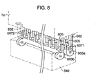
- Fig. 8 is a schematic view of a structure of a connecting portion where the connecting transfer path (transfer path connecting means) is connected to an upper bill transfer mechanism.
- Hereunder, a preferred embodiment of the present invention will be described with reference to the accompanying drawings.
- Fig. 1 is a perspective view of an appearance of an embodiment of an automatic cash handling machine according to the present invention.
- An automatic
cash handling machine 101 is housed in a machine cabinet 101'. In a left side inside the case 101' are provided a card/detailslip processing mechanism 102 communicated with acard slot 102a located at atop front panel 101a and enabled to process customer cards and print out transaction detail slips, then discharge the slips; and acustomer panel 105 enabled to display and enter contents of each transaction. In the right side inside the machine is provided a bill depositing/withdrawingmechanism 1 that processes bills. And, abill slot 20a is provided at the top-inclinedfront board 101b. - The lower bill stacker of the bill depositing/withdrawing
mechanism 1 is housed in asafe cabinet 106 composed of an iron plate of a few tens of millimeters in thickness separately from the machine cabinet 101'. Although the machine cabinet 101' is strong in structure, thesafe cabinet 106 is structured more strongly so as to improve the security. This automaticcash handling machine 101 enables users to deposit, withdraw, and transfer money with use of cards, bills, and detail slips. - Fig. 2 shows a block diagram of a control relation of an embodiment of the automatic
cash handling machine 101. As described above, the card/detailslip processing mechanism 102, the bill depositing/withdrawingmechanism 1, and thecustomer panel 105 housed in the automaticcash handling machine 101 are connected to amain controller 107 via abus 107a so as to enable the customers to execute necessary operations under the control of thecontroller 107. - In addition to the above items, the
controller 107 is also connected to aninterface unit 107b, anoperator panel 107c, and anexternal memory 107d via thebus 107a so as to send/receive necessary data.Reference number 108 in Fig. 2 denotes a power unit that supplies a power to each of the components of themachine 101. - Fig. 3 is a side view showing a configuration of an embodiment of the bill depositing/withdrawing
mechanism 1 in Fig. 1. The bill depositing/withdrawingmechanism 1 is composed of a depositing/withdrawingport 20 that enables users to deposit/withdraw bills; abill checker 30 for checking bills; atemporary stacker 40 for holding deposited bills until the transaction is established; a depositingcassette 60 for holding bills after the depositing transaction is established; a withdrawingcassette 70 for holding bills to be withdrawn; tworecycling cassette 80 used for both depositing and withdrawing respectively; a loading/collectingcassette 81 for holding bills to be replenished in therecycling cassette 80 and collected from the two recycling saves; abill transfer path 50 for transferring bills to the depositing/withdrawingport 20, thetemporary stacker 40, the depositingcassette 60, the withdrawingcassette 70, therecycling cassettes 80, and the loading/collectingcassette 81 respectively via thebill checker 30; and a controller (not shown). - In the above example, while the bill depositing/withdrawing
port 20 is composed so as to be used as both a depositing port and a withdrawing port, it is not necessarily composed such way; the depositing port for transferring bills deposited by customers into the machine may be provided separately from the withdrawing port for holding bills to be withdrawn by customers. - Fig. 4 is a controlling block diagram for explaining a control relation of an embodiment of the bill depositing/withdrawing
mechanism 1. As shown in Fig. 4, thecontroller 10 of the bill depositing/withdrawingmechanism 1 is connected to themain controller 107 of the automaticcash handling machine 101 via thebus 107a, so that thecontroller 10 controls the bill depositing/withdrawingmechanism 1 according to the instruction from themain controller 107 and the detected state of the bill depositing/withdrawingmechanism 1. Thecontroller 10 also sends the state of the bill depositing/withdrawingmechanism 1 to themain controller 107 via thebus 107a as needed. In addition, in the bill depositing/withdrawingmechanism 1, thecontroller 10 is connected to the driving motor, the electromagnetic solenoid, and the sensor (not shown) of each unit (depositing/withdrawingport 20;bill checker 30;temporary stacker 40;bill transfer path 50; depositingcassette 60; withdrawingcassette 70;recycling cassettes 80; and loading/collecting cassette 81), so that thecontroller 10 controls driving of an actuator for each transaction while monitoring the state of the unit via the sensor. - The bill depositing/withdrawing
mechanism 1, as shown in Fig. 3, is composed of anupper bill mechanism 1a and alower bill mechanism 1b. Theupper bill mechanism 1a is composed of a depositing/withdrawingport 20; abill checker 30; atemporary stacker 40; and abill transfer path 50. Thelower bill mechanism 1b is composed of a depositingcassette 60; a withdrawingcassette 70; tworecycling cassettes 80; a loading/collectingcassette 81; and atransfer path 90 disposed in front of each bill stacker. - Furthermore, the
lower bill mechanism 1b is housed in a cassette cabinet (protective cabinet) 106 made of an iron plate having a thickness of about 50mm. The (upper) transfer path of theupper bill mechanism 1a and the (lower) transfer path of thelower bill mechanism 1b are connected to each other via a connecting transfer path (transfer path connecting means) 540, so that bills are transferred between the upper andlower bill mechanisms transfer path 540. - More concretely, the connecting
transfer path 540 is built in the top iron plate of the cassette cabinet (protective cabinet) 106 in which thelower bill mechanism 1b is housed at a place where thetransfer path 501i of theupper bill mechanism 1a is connected to thetransfer path 901a of thelower bill mechanism 1b as shown in Fig. 3. The slit opened at the top iron plate is sized enough to pass bills and equally to the width of the transfer roller attached so as to pinch and transfer bills passed through the slit. - The driving source (motor) of the transfer path may be provided at the (upper) transfer path of the
upper bill mechanism 1a and at the (lower) transfer path of thelower bill mechanism 1b separately. However, it is also possible to use a single driving source for transmitting a driving power to each of the transfer paths with use of a gear provided in thetransfer paths - The
bill transfer path 50 that passes through both sides of thebill checker 30 is connected to the depositing/withdrawingport 20; thetemporary stacker 40; the depositingcassette 60; the withdrawingcassette 70; therecycling cassettes 80; and the loading/collectingcassette 81 via the transfer paths denoted byarrows 501a to 501h andarrows 901a to 901e. Each one-way arrow denotes a one-way bill transfer path for transferring bills only in that direction and each two-way arrow denotes a two-way transfer path switchable in any of the two directions in which bills are transferred in each transaction. In this embodiment, all the transfer paths are two-way paths, since the bill handling machine is used for depositing and withdrawing bills. When the bill handling machine is used only for withdrawing bills, however, those transfer paths may be one-way paths. - Furthermore, at each branch of the
bill transfer path 50 are provided twoselector gates 502 and 503, as well as other five selector gates 902. Each gate is positioned at a or b at each processing so as to select a bill transfer direction. With such the configuration employed for the bill depositing/withdrawingmechanism 1, each user is enabled to deposit/withdraw bills while the operator is enabled to load/collect bills. - At first, a depositing processing for the automatic cash handling machine will be described. When a user deposits bills through the depositing/withdrawing
port 20, the bills are separated one by one and each bill is checked for both type and authenticity in thebill checker 30. Each bill checked by thebill checker 30 is transferred through theselector gate 503 positioned appropriately to the bill type and held in thetemporary stacker 40. - A bill, when it is rejected by the
bill checker 30 because of an error (abnormally eccentric, abnormal spacing (bills are stacked on top of one another)), is not transferred into thetemporary stacker 40, but it is returned to the depositing/withdrawingport 20 through theselector gate 503 positioned in accordance with the rejection. The user is thus requested to take the rejected bill from theport 20. - When the depositing processing is established, the bills held in the
temporary stacker 40 are transferred in the reverse direction in the reverse order they are held there to pass thebill checker 30. Each bill, which passes thebill checker 30, goes through the selector gate 502 positioned so as to select thedirection 502a into the specified safe through the gate 903 of any of the depositingcassette 60, therecycling cassettes 80, and a rejection cassette. The selector gate 903 is positioned so as to select thedirection 903b at this time. This completes the depositing processing. - Next, a withdrawing processing will be described. A withdrawing processing begins first with unloading the predetermined number of bills from the safe of each bill type provided in the withdrawing
cassette 70 and therecycle cassettes 80 respectively. The bills are then transferred to thebill checker 30 and checked for bill type respectively. Then, theselector gate 503 is positioned so as to transfer the checked bills towards the depositing/withdrawing port. The bills, when passing thebill checker 30, are held at the depositing/withdrawingport 20 so that the user can take them by opening the upper shutter of theslot 20a. When the user picks up the bills from theport 20, the withdrawing processing is terminated. - Next, processings for loading and collecting bills in/from the
recycling cassettes 80 will be described. Loading and collecting of bills are done by transferring bills among the loading/collectingcassette 81, thetemporary stacker 40, and therecycle cassettes 80. - At first, loading of bills will be done as follows. Bills are set in the loading/collecting
cassette 81 at a time, then they are held in therecycle cassettes 80 automatically in the machine. A collecting processing is done so as to collect the predetermined number of bills from therecycle cassettes 80, then load them in the loading/collectingcassette 81 automatically, for example, when therecycle cassettes 80 become full. Collecting of bills is thus done in the reverse order of the loading of bills. - This completes the description of the basic processings of the bill depositing/withdrawing
mechanism 1. This bill depositing/withdrawingmechanism 1 is installed in the right side in the automaticcash handling machine 101 as shown in Fig. 1. - Next, a configuration of the bill depositing/withdrawing
mechanism 1 will be described with reference to Figs. 5A to 5C with respect to the controllability from the viewpoint of the operator. The automaticcash handling machine 101 in this embodiment can take any of the configuration for doing maintenance from the front side of the machine 101 (front side operation type) and the configuration for doing maintenance from the rear side (rear side operation type). In any configuration, the upper andlower bill mechanisms machine 101 as needed with use of an employed sliding mechanism such as a sliding rail or the like. While both of the upper andlower bill mechanisms mechanisms - When a maintenance work is done for the
upper bill mechanism 1a from the front side of the machine 101 (front side operation type), a lock mechanism (not shown) is reset from the front side of themachine 101, then the surface-inclinedtop panel 101b is raised so as to open as shown in Fig. 5A, then theupper bill mechanism 1a is pulled out from themachine 101 towards the front side along the slidingrail mechanism 151. Thus, the maintenance work is enabled. - A maintenance work for the
lower bill mechanism 1b can be done as follows. The lock mechanism (not shown) is reset so as to open thefront door 101c of themachine 101. Then, thefront door 106a of thecassette cabinet 106 is opened by unlocking the lock (not shown). After this, thelower bill mechanism 1b is pulled out to this side from the bill depositing/withdrawingmechanism 1 along the slidingrail mechanism 152. Now, the maintenance work can be done. - When a maintenance work is done from the rear side of the machine 101 (rear side operation type), the lock mechanism (not shown) is reset from the rear side as shown in Fig. 5B, then the
rear door 101d of themachine 101 is opened. After this, theupper bill mechanism 1a is pulled out from the bill depositing/withdrawingmechanism 1 along the slidingrail mechanism 151 as shown in Fig. 5C. Now, the maintenance work can be done. - Furthermore, the lock (not shown) of the
rear door 106b of thecassette cabinet 106 is unlocked so as to open it, then thelower bill mechanism 1b is pulled out from the depositing/withdrawingmechanism 1 along the slidingrail mechanism 152. Now, the maintenance work can be done. - As described above, the bill depositing/withdrawing
mechanism 1 in this embodiment is enabled for any of the front side operation configuration that enables maintenance from the front side and the rear side operation configuration that enables maintenance from the rear side of themachine 101. - Figs. 6A to 6F show a concrete example of the connecting transfer path (transfer path connecting means) 540 in this embodiment with respect to an operation for returning the removed
upper bill mechanism 1a to the reference position. Fig. 6A through Fig. 6C show how theupper bill mechanism 1a, which has been pulled out for a maintenance work, is slid in the direction of thearrow 601 and returned to thereference position 610 from the rear side of themachine 101. - Here, a description will be made first for the structure of the connecting portion between the connecting transfer path (transfer path connecting means) 540 and the
upper bill mechanism 1a with reference to Fig. 8. As shown in Fig. 8, an end portion of eachtransfer guide 605 is formed like a comb at the connecting portion of theupper bill mechanism 1a. The transfer guides 605 are provided at both sides of the transfer path in theupper bill mechanism 1a. And, afirst projection 602 is fixed to the end portion of eachtransfer guide 605 with screws, etc. The fixing position of thefirst projection 602 is varied according to whether theupper bill mechanism 1a is pulled out towards the front side or rear side of themachine 101. When themechanism 1a is pulled out towards the front side, thefirst projection 602 is fixed to the position denoted by a solid line in Fig. 8. When themechanism 1a is pulled out towards the rear side, the first projection is fixed to the position denoted by a dotted line in Fig. 8. - The connecting transfer path (transfer path connecting means) 540 is provided with comb-like opening/closing guides A 603a and
B 603b to be engaged with the right and left comb-like transfer guides 605 respectively. The opening/closing guides A 603a andB 603b are enabled to rotate around an axis respectively. Usually, each of the guides A 603a andB 603b is pressed to open by such an elastic mechanism as a spring. - The
guide A 603a is provided with asecond projection 6071 at a place where theguide A 603a comes in contact with thefirst projection 602. Theguide B 603b is provided with asecond projection 6072 denoted by a dotted line in Fig. 8 at a place where theguide B 603b comes in contact with thefirst projection 602 whose position is changed to a position denoted by a dotted line as described above so as to enable theupper bill mechanism 1a to be inserted from the other direction (for example, from the front side of the machine 101). - When the
upper bill mechanism 1a is inserted into themachine 101 from one direction, thefirst projection 602 presses thesecond projection 6071 to come in contact with a guide. For example, when theupper bill mechanism 1a is installed from the rear side of themachine 101, thefirst projection 602 located this side in Fig. 8 is pressed against the transfer path by thesecond projection 6071 provided at the opening/closing guide 603a located at the rear side of themachine 101, thereby theprojection 602 rotates counter-clockwise around the axis. On the contrary, when themechanism 1a is installed from the front side of themachine 101, thesecond projection 6072 provided at the opening/closing guide 603b located at the front side of themachine 101 is pressed against the transfer path by thefirst projection 602 located at the other side in Fig. 8, thereby theprojection 6072 rotates clockwise around the axis. When theupper bill mechanism 1a is slid, therefore, the opening/closing guides 603a and 603b, against the spring elastic powers, come to be engaged with the transfer guides 605 of the upper bill mechanism. - Although not shown in Fig. 8, the guides A 603a and
B 603b are connected to each other via a gear (see 606 in Figs. 6A to 6F) so as to open together in this embodiment. Consequently, due to this configuration, when one opening/closing guide (603a or 603b) is pressed, two opening/closing guides 603a and 603b can be engaged together with the transfer guides 605 of the upper bill mechanism. - Next, a description will be made for an operation for returning the pulled-out
upper bill mechanism 1a to the reference position with reference to Figs. 6A to 6F. Fig. 7A through Fig. 7C are expanded views of thefirst projection 602, thesecond projection 6071, the opening/closing guide A 603a, and the opening/closing guide B 603b shown in Fig. 6A through Fig. 6C so as to make it easier to understand the above operation. - In Figs. 6A to 6F or 7A to 7C, the opening/closing guides A 603a and
B 603b are different from each other in length. This is because the transfer guides 605 of theupper bill mechanism 1a, to be engaged with them respectively, are also different from each other in length. Concretely, thetransfer guide 605 to be engaged with theguide B 603b is provided with the function of a selector gate for selecting a direction of the two-way transfer described above. Thetransfer guide 605 thus rotates to a position denoted by a dotted line in Fig. 6A according to the selected transfer direction. And, one of the transfer guides 605 is formed shorter than the other so as not to come in contact with other peripheral members when thetransfer guide 605 rotates. - Fig. 6A and Fig. 7A show how the
upper bill mechanism 1a, which is pulled out to the rear side of themachine 101, is pushed into the machine 101 (rear side operation type). In this case, thefirst projection 602 of theupper bill mechanism 1a presses thesecond projection 6071 of the opening/closing guide A 603a, thereby the opening/closing guide A 603a is rotated in the direction of thearrow 604a (see Fig. 6B/Fig. 7B). As described above, the opening/closing guide A 603a is connected to the opening/closing guide B 603b via thegear 606, so that theguide A 603a is rotated in the direction of thearrow 604b (see Fig. 6B/Fig. 7B). - When the
upper bill mechanism 1a is further pushed in, the opening/closing guide A 603a is closed and connected to theright transfer guide 605 provided in theupper bill mechanism 1a. Then, the opening/closing guide B 603b ganged with the opening/closing guide A 603a via thegear 606 is also connected to theleft transfer guide 605 provided in theupper bill mechanism 1a. Fig. 6C and Fig. 7C show how the opening/closing guides A 603a andB 603b are connected to the right and left transfer guides 605. Because theupper bill mechanism 1a is connected to the connecting transfer path such way, loaded bills are transferred along atransfer belt 611. - Fig. 6D through Fig. 6F show how the
upper bill mechanism 1a, which is pulled out to the front side of themachine 101, is pushed into themachine 101 from the front side (front side operation type). The operation states as shown in Fig. 6D through Fig. 6F are the same as those shown in Fig. 6A through Fig. 6C except that theupper bill mechanism 1a is pushed into the machine from the front side. The description for the operation states will thus be omitted here. In the case of the operations shown in Fig. 6D through Fig. 6F, the fixing position of thefirst projection 602 must be changed from that shown in Fig. 6A through Fig. 6C. And, in this case, thesecond projection 6072 fixed to the opening/closing guide B 603b is used as shown in Fig. 6D through Fig. 6F. - While a description is made for pushing the
upper bill mechanism 1a up to thereference position 610 in the above embodiment, thelower bill mechanism 1b can also be pushed up to thereference position 610 in the same way, since a pair of guides to be opened/closed by the springs are also provided at the bottom face of the connecting transfer path (transfer path connecting means) 540. - Furthermore, the
upper bill mechanism 1a orlower bill mechanism 1b pushed up to thereference position 610 in themachine 101 is pulled out from themachine 101 in the order as shown in "Fig. 6C or Fig. 7C" → "Fig. 6B or Fig. 7B" → "Fig. 6A or Fig. 7A" or Fig. 6F → Fig. 6E → Fig. 6D. - As apparent from the above description, when the
upper bill mechanism 1a orlower bill mechanism 1b is pulled out from the machine 101 (from the front side or rear side of the machine 101), no bill is broken and/or the opening/closing guides A 603a andB 603b are prevented from damages even when a bill remains (jams) around the connecting transfer path (transfer path connecting means) 540, since the opening/closing guides A 603a andB 603b are pressed so as to open by springs, etc., thereby those guides A and B are opened step by step as themechanism 1a/1b is pulled out. - While both of the opening/closing guides A 603a and
B 603b are provided in the above embodiment, so that both of the guides A and B are opened when a unit is pulled out from themachine 101, the present invention is not limited only to that configuration; it is also possible to use only one guide. - Furthermore, while the opening/closing guides A 603a and
B 603b are different from each other in length in the above embodiment, those guides A and B may be equal in length, for example, when the transfer path is not two-way, when none of the transfer guides has a selector gate function, and when there is provided a space enough for enabling the selector gate to rotate. The present invention can apply even to such the case, of course. - Furthermore, when a transfer guide to be engaged with an opening/
closing guide A 603a/B 603b is protruded from the unit, only one of the opening/closing guides A 603a andB 603b may be opened so as to remove/install the unit. Concretely, the unit is installed while only the longer opening/closing guides A 603a is opened and the shorter opening/closing guide B 603b is closed. This is because no problem arises from the sliding of the unit even when the shorter opening/closing guide B 603b is closed in the case where the transfer guides are protruded from the unit. However, the unit is removed/installed only from the side where the longer opening/closing guide A 603a is located, that is, the guide to be opened is located. In this case, the gear used to connect opening/closing guides A and B to each other in the above embodiment may be omissible. And, as described above, when the opening/closing guides A 603a andB 603b are equal in length, any of the guides A and B may be closed, of course. - According to the present invention, therefore, it is possible to prevent bills from jams around the transfer path connecting means used to connect divided bill transfer means, as well as prevent any of the divided transfer means and guides that are members of the transfer path connecting means from damages when any of the divided transfer means is pulled out from the machine for maintenance.
Claims (9)
- A bill handling machine (1) for depositing or/and withdrawing bills, comprising:a first unit (1a) provided with a port (20) for depositing/withdrawing bills;a second unit (1b) provided with a cassette (60, 70, 80, 81) for holding bills; anda bill transfer mechanism (50, 90) for transferring bills between said port (20) and said cassette (60, 70, 80, 81),wherein at least one of said first and second units (1a, 1b) is removable; andsaid bill transfer mechanism (50, 90) includes:a first transfer mechanism (605) provided inside said removable unit (1a), anda connecting transfer mechanism (540) connected to said first transfer mechanism (605) and operable with the removing/installing of said removable unit (1a) so as to control the connection with said first transfer mechanism (605),characterised in that said connecting transfer mechanism (540) is provided with guide means (603a, 603b) adapted to engage said first transfer mechanism (605) to guide bills, the guide means being provided with a second projection (6071, 6072) located at a place where said guide means (603a, 603b) comes into contact with a first projection (602) provided on said removable unit which presses against said second projection (6071, 6072) to bring said connecting transfer mechanism (540) into connection with said first transfer mechanism (605) when said removable unit (1a) is installed in said machine.
- The machine of claim 1, wherein said guide means includes first and second guides (603a, 603b) connected to each other via a connecting member (606).
- The machine of claim 1 or 2, wherein said second projection (6071) is located at the guide (603a, 603b) disposed on that side from which said removable unit (1a) is installed.
- The machine of claim 1, wherein
said guide means includes first and second guides (603a, 603b) connected to each other via a connecting member (606); and
said first guide (603a) is longer, thus capable of protruding further from said connecting transfer mechanism (540), than said second guide (603b). - The machine of claim 4, wherein
said second projection (6071, 6072) is located on an outer side of said first guide (603a); and
said removable unit (1a) is removed/installed from the side of said first guide (603a). - The machine of claim 2 or 4, wherein said first and second guides (603a, 603b) are pressed by elastic members so as to open.
- The machine of claim 1, further comprising a protective cabinet (106) for housing said second unit (1b), wherein said second unit (1b) includes a safe and said connecting transfer mechanism (540) is housed in said protective cabinet (106).
- The machine of claim 1, wherein, when said removable unit (1a) is pulled out, said guide means (603a, 603b) comes into an open state.
- The machine of claim 1, wherein
said guide means includes first and second guides (603a, 603b) connected to each other via a connecting member (606), and
said first and second guides (603a, 603b) are pressed by elastic members so as to open respectively.
Applications Claiming Priority (2)
| Application Number | Priority Date | Filing Date | Title |
|---|---|---|---|
| JP2000358077A JP3916035B2 (en) | 2000-11-24 | 2000-11-24 | Banknote handling equipment |
| JP2000358077 | 2000-11-24 |
Publications (3)
| Publication Number | Publication Date |
|---|---|
| EP1209633A2 EP1209633A2 (en) | 2002-05-29 |
| EP1209633A3 EP1209633A3 (en) | 2004-03-10 |
| EP1209633B1 true EP1209633B1 (en) | 2007-10-10 |
Family
ID=18830043
Family Applications (1)
| Application Number | Title | Priority Date | Filing Date |
|---|---|---|---|
| EP01127961A Expired - Lifetime EP1209633B1 (en) | 2000-11-24 | 2001-11-23 | Bill handling machine |
Country Status (6)
| Country | Link |
|---|---|
| US (1) | US6695307B2 (en) |
| EP (1) | EP1209633B1 (en) |
| JP (1) | JP3916035B2 (en) |
| KR (1) | KR100417268B1 (en) |
| DE (1) | DE60130861T2 (en) |
| TW (1) | TW505902B (en) |
Cited By (2)
| Publication number | Priority date | Publication date | Assignee | Title |
|---|---|---|---|---|
| CN101425197B (en) * | 2007-11-02 | 2011-01-26 | 日立欧姆龙金融系统有限公司 | Paper money receiving/dispensing mechanism and automatic teller machine |
| DE102009038175A1 (en) | 2009-08-20 | 2011-02-24 | Wincor Nixdorf International Gmbh | Device and method for handling notes of value |
Families Citing this family (43)
| Publication number | Priority date | Publication date | Assignee | Title |
|---|---|---|---|---|
| RU2297668C2 (en) * | 2002-10-18 | 2007-04-20 | Дайболд, Инкорпорейтед | Banking machine, which dispenses, receives and stores bank notes and other financial documents in form of sheets |
| ITMI20030454A1 (en) * | 2003-03-11 | 2004-09-12 | Razzaboni Cima Spa | MACHINE FOR ORDERED STORAGE AND BANKNOTE ISSUE. |
| JP2006209603A (en) * | 2005-01-31 | 2006-08-10 | Hitachi Omron Terminal Solutions Corp | Paper sheet handling device |
| US7322517B1 (en) * | 2005-06-03 | 2008-01-29 | Diebold Self-Service Systems Division Of Diebold, Incorporated | Enclosure for automated banking machine |
| US7367493B1 (en) * | 2005-06-03 | 2008-05-06 | Diebold Self-Serice Systems Division Of Diebold, Incorporated | Enclosure for automated banking machine |
| JP4730946B2 (en) * | 2005-06-17 | 2011-07-20 | 株式会社ユニバーサルエンターテインメント | Banknote processing apparatus and control system for banknote processing apparatus |
| JP2007034602A (en) * | 2005-07-26 | 2007-02-08 | Hitachi Omron Terminal Solutions Corp | Paper sheet discrimination device |
| JP4942330B2 (en) * | 2005-11-21 | 2012-05-30 | 日立オムロンターミナルソリューションズ株式会社 | Paper sheet handling equipment |
| ES2357170T3 (en) * | 2006-09-05 | 2011-04-19 | Mei, Inc. | BULK DOCUMENT FEEDER WITH REMOVABLE CARTRIDGE. |
| JP4368888B2 (en) * | 2006-12-15 | 2009-11-18 | 日立オムロンターミナルソリューションズ株式会社 | Paper sheet storage and paper sheet handling device |
| GB0702191D0 (en) * | 2007-02-05 | 2007-03-14 | Innovative Technology Ltd | Improvements Relating to Banknote Validation |
| EP2015259A1 (en) * | 2007-07-12 | 2009-01-14 | MEI, Inc. | Banknote handling apparatus |
| DE102007060803A1 (en) * | 2007-12-18 | 2009-06-25 | Wincor Nixdorf International Gmbh | Apparatus and method for storing banknotes |
| JP5122325B2 (en) | 2008-02-26 | 2013-01-16 | 日立オムロンターミナルソリューションズ株式会社 | Paper sheet transport mechanism and paper sheet handling device |
| US8025214B1 (en) | 2008-07-31 | 2011-09-27 | Bank Of America Corporation | Cash handling device having integrated controller |
| JP5156532B2 (en) | 2008-08-06 | 2013-03-06 | 日立オムロンターミナルソリューションズ株式会社 | Banknote handling equipment |
| US8181856B1 (en) | 2008-11-25 | 2012-05-22 | Bank Of America Corporation | Cash handling device having alert system |
| JP5205292B2 (en) * | 2009-01-16 | 2013-06-05 | ローレル機械株式会社 | Banknote handling machine |
| JP5268667B2 (en) * | 2009-01-16 | 2013-08-21 | ローレル機械株式会社 | Banknote handling machine |
| JP5216805B2 (en) * | 2010-04-30 | 2013-06-19 | 日立オムロンターミナルソリューションズ株式会社 | Paper sheet processing equipment |
| JP5633451B2 (en) * | 2011-03-29 | 2014-12-03 | 沖電気工業株式会社 | Banknote handling device and delivery unit used for the banknote handling device |
| TWI456529B (en) * | 2011-07-26 | 2014-10-11 | 日立歐姆龍金融系統有限公司 | Paper sheet processing device |
| JP5845996B2 (en) * | 2012-03-26 | 2016-01-20 | 沖電気工業株式会社 | Media processing device |
| JP5511109B2 (en) * | 2013-03-04 | 2014-06-04 | 日立オムロンターミナルソリューションズ株式会社 | Paper sheet processing equipment |
| JP6146080B2 (en) * | 2013-03-26 | 2017-06-14 | セイコーエプソン株式会社 | Recording device |
| JP6291948B2 (en) * | 2014-03-25 | 2018-03-14 | 沖電気工業株式会社 | Banknote handling equipment |
| JP6216685B2 (en) * | 2014-05-30 | 2017-10-18 | 日立オムロンターミナルソリューションズ株式会社 | Banknote handling equipment |
| JP2016099677A (en) | 2014-11-18 | 2016-05-30 | グローリー株式会社 | Banknote handling device |
| KR101719765B1 (en) * | 2015-02-13 | 2017-04-04 | 노틸러스효성 주식회사 | Automatic teller machine and gate apparatus for guiding bills thereof |
| TWI602158B (en) | 2016-08-05 | 2017-10-11 | 鴻發國際科技股份有限公司 | Bill handling apparatus and engaging module |
| GB2560315A (en) * | 2017-03-06 | 2018-09-12 | Innovative Tech Ltd | A safe conduit device |
| JPWO2018168465A1 (en) | 2017-03-15 | 2020-01-16 | グローリー株式会社 | Banknote handling equipment |
| WO2018195683A1 (en) * | 2017-04-24 | 2018-11-01 | 深圳怡化电脑股份有限公司 | Automatic deposit and withdrawal machine |
| EP3509042B1 (en) * | 2018-01-03 | 2021-09-15 | Wincor Nixdorf International GmbH | Device for handling notes of value |
| CN110288756B (en) * | 2018-03-13 | 2021-12-21 | 山东新北洋信息技术股份有限公司 | Sheet-like medium conveying device and cash recycling device |
| JP7275479B2 (en) * | 2018-05-22 | 2023-05-18 | 沖電気工業株式会社 | Banknote processing device and banknote transaction device |
| US10977889B1 (en) * | 2018-07-18 | 2021-04-13 | G4S Retail Solutions (USA) Inc. | Cloud-based cash inventory management for on-premises cash handling devices |
| US11315379B1 (en) | 2018-11-30 | 2022-04-26 | G4S Retail Solutions (USA) Inc. | Systems and methods for cash-till optimization |
| US11669912B1 (en) | 2019-07-15 | 2023-06-06 | G4S Retail Solutions (USA) Inc. | Cash loss exception and reconciliation system and method |
| EP3985626A1 (en) * | 2020-10-16 | 2022-04-20 | Wincor Nixdorf International GmbH | Arrangement for securing access to a device for handling banknotes |
| US11915540B1 (en) | 2021-03-19 | 2024-02-27 | Wells Fargo Bank, N.A. | Systems and methods for two-way cash recycler |
| WO2023161978A1 (en) * | 2022-02-22 | 2023-08-31 | 富士通フロンテック株式会社 | Paper sheet handling device |
| US11688249B1 (en) * | 2022-06-21 | 2023-06-27 | Ncr Corporation | Media item transport |
Family Cites Families (12)
| Publication number | Priority date | Publication date | Assignee | Title |
|---|---|---|---|---|
| GB2046975A (en) * | 1979-04-11 | 1980-11-19 | De La Rue Syst | Cash dispensing apparatus |
| JPS5810265A (en) * | 1981-07-10 | 1983-01-20 | Toshiba Corp | Automatic transaction device for currency |
| JPS59205693A (en) * | 1983-05-06 | 1984-11-21 | オムロン株式会社 | Paper money processor |
| FR2587012B1 (en) * | 1985-09-11 | 1987-10-23 | Dassault Electronique | AUTOMATIC BANK NOTES DISTRIBUTOR |
| JPS62230546A (en) * | 1986-03-31 | 1987-10-09 | Oki Electric Ind Co Ltd | Medium insertional guide device |
| JPH03243548A (en) * | 1990-02-21 | 1991-10-30 | Fujitsu Ltd | Paper jamming removal method for paper feeder |
| US5326092A (en) * | 1992-01-10 | 1994-07-05 | Kabushiki Kaisha Toshiba | Apparatus for conveying a paper along with a paper conveying path |
| JPH05201561A (en) * | 1992-01-23 | 1993-08-10 | Casio Electron Mfg Co Ltd | Image forming device |
| JP2947461B2 (en) * | 1994-01-13 | 1999-09-13 | 沖電気工業株式会社 | Automatic machine group management device |
| DE19609866C2 (en) * | 1996-03-13 | 1998-07-30 | Siemens Nixdorf Inf Syst | ATM |
| JP4135238B2 (en) | 1998-12-08 | 2008-08-20 | 日立オムロンターミナルソリューションズ株式会社 | Banknote deposit and withdrawal machine |
| JP2000318862A (en) * | 1999-05-10 | 2000-11-21 | Ricoh Co Ltd | Paper feeding device |
-
2000
- 2000-11-24 JP JP2000358077A patent/JP3916035B2/en not_active Expired - Fee Related
-
2001
- 2001-11-02 TW TW090127333A patent/TW505902B/en not_active IP Right Cessation
- 2001-11-20 US US09/988,800 patent/US6695307B2/en not_active Expired - Lifetime
- 2001-11-23 DE DE60130861T patent/DE60130861T2/en not_active Expired - Lifetime
- 2001-11-23 EP EP01127961A patent/EP1209633B1/en not_active Expired - Lifetime
- 2001-11-23 KR KR10-2001-0073363A patent/KR100417268B1/en not_active IP Right Cessation
Cited By (5)
| Publication number | Priority date | Publication date | Assignee | Title |
|---|---|---|---|---|
| CN101425197B (en) * | 2007-11-02 | 2011-01-26 | 日立欧姆龙金融系统有限公司 | Paper money receiving/dispensing mechanism and automatic teller machine |
| CN101901514B (en) * | 2007-11-02 | 2012-11-28 | 日立欧姆龙金融系统有限公司 | Paper money receiving/dispensing mechanism and automatic teller machine |
| DE102009038175A1 (en) | 2009-08-20 | 2011-02-24 | Wincor Nixdorf International Gmbh | Device and method for handling notes of value |
| WO2011020904A1 (en) | 2009-08-20 | 2011-02-24 | Wincor Nixdorf International Gmbh | Device and method for handling value notes |
| US8764011B2 (en) | 2009-08-20 | 2014-07-01 | Wincor Nixdorf International Gmbh | Device and method for handling value notes |
Also Published As
| Publication number | Publication date |
|---|---|
| TW505902B (en) | 2002-10-11 |
| DE60130861D1 (en) | 2007-11-22 |
| JP2002163704A (en) | 2002-06-07 |
| KR100417268B1 (en) | 2004-02-05 |
| US20020074709A1 (en) | 2002-06-20 |
| DE60130861T2 (en) | 2008-05-15 |
| US6695307B2 (en) | 2004-02-24 |
| EP1209633A3 (en) | 2004-03-10 |
| KR20020040640A (en) | 2002-05-30 |
| JP3916035B2 (en) | 2007-05-16 |
| EP1209633A2 (en) | 2002-05-29 |
Similar Documents
| Publication | Publication Date | Title |
|---|---|---|
| EP1209633B1 (en) | Bill handling machine | |
| EP2128831B1 (en) | Bill receiving and dispensing apparatus | |
| US6719120B2 (en) | Bill receiving/dispensing machine | |
| JP3791189B2 (en) | Banknote deposit and withdrawal machine | |
| EP2963625B1 (en) | Medium processing apparatus | |
| JP2002260057A (en) | Paper money teller machine | |
| JP2016146142A (en) | Paper sheet processing machine and paper sheet processing method | |
| JP3451988B2 (en) | Banknote cassette | |
| US7370792B1 (en) | Automated transaction machine | |
| US7870996B1 (en) | Automated transaction machine | |
| US11315391B2 (en) | Automatic teller machine having a note storage unit with a door capable of being locked and unlocked | |
| EP2332125B1 (en) | Removable currency storage unit with content access monitoring | |
| JP6891924B2 (en) | Media processing equipment | |
| JP3799320B2 (en) | Banknote cassette and banknote handling device | |
| JP6927820B2 (en) | Banknote processing system and storage | |
| JPH0334093A (en) | Automatic teller machine | |
| CN108510642B (en) | Automatic cash transaction device | |
| KR970006656B1 (en) | Atm | |
| JP3575330B2 (en) | Paper storage device | |
| KR102063616B1 (en) | Automatic teller machine having medium storage and the control method thereof | |
| JP3902980B2 (en) | Automatic transaction equipment | |
| JP3799321B2 (en) | Banknote cassette and automatic transaction device | |
| JPH08153265A (en) | Device with door drop preventing mechanism | |
| US7748613B1 (en) | Automated transaction machine | |
| US7721950B1 (en) | Automated transaction machine |
Legal Events
| Date | Code | Title | Description |
|---|---|---|---|
| PUAI | Public reference made under article 153(3) epc to a published international application that has entered the european phase |
Free format text: ORIGINAL CODE: 0009012 |
|
| AK | Designated contracting states |
Kind code of ref document: A2 Designated state(s): AT BE CH CY DE DK ES FI FR GB GR IE IT LI LU MC NL PT SE TR |
|
| AX | Request for extension of the european patent |
Free format text: AL;LT;LV;MK;RO;SI |
|
| PUAL | Search report despatched |
Free format text: ORIGINAL CODE: 0009013 |
|
| AK | Designated contracting states |
Kind code of ref document: A3 Designated state(s): AT BE CH CY DE DK ES FI FR GB GR IE IT LI LU MC NL PT SE TR |
|
| AX | Request for extension of the european patent |
Extension state: AL LT LV MK RO SI |
|
| 17P | Request for examination filed |
Effective date: 20040331 |
|
| AKX | Designation fees paid |
Designated state(s): DE FR GB |
|
| 17Q | First examination report despatched |
Effective date: 20041228 |
|
| RAP1 | Party data changed (applicant data changed or rights of an application transferred) |
Owner name: HITACHI-OMRON TERMINAL SOLUTIONS, CORP. |
|
| GRAP | Despatch of communication of intention to grant a patent |
Free format text: ORIGINAL CODE: EPIDOSNIGR1 |
|
| GRAS | Grant fee paid |
Free format text: ORIGINAL CODE: EPIDOSNIGR3 |
|
| GRAA | (expected) grant |
Free format text: ORIGINAL CODE: 0009210 |
|
| AK | Designated contracting states |
Kind code of ref document: B1 Designated state(s): DE FR GB |
|
| REG | Reference to a national code |
Ref country code: GB Ref legal event code: FG4D |
|
| REF | Corresponds to: |
Ref document number: 60130861 Country of ref document: DE Date of ref document: 20071122 Kind code of ref document: P |
|
| ET | Fr: translation filed | ||
| PLBE | No opposition filed within time limit |
Free format text: ORIGINAL CODE: 0009261 |
|
| STAA | Information on the status of an ep patent application or granted ep patent |
Free format text: STATUS: NO OPPOSITION FILED WITHIN TIME LIMIT |
|
| 26N | No opposition filed |
Effective date: 20080711 |
|
| REG | Reference to a national code |
Ref country code: FR Ref legal event code: PLFP Year of fee payment: 15 |
|
| REG | Reference to a national code |
Ref country code: FR Ref legal event code: PLFP Year of fee payment: 16 |
|
| PGFP | Annual fee paid to national office [announced via postgrant information from national office to epo] |
Ref country code: DE Payment date: 20161116 Year of fee payment: 16 Ref country code: FR Payment date: 20161014 Year of fee payment: 16 Ref country code: GB Payment date: 20161123 Year of fee payment: 16 |
|
| REG | Reference to a national code |
Ref country code: DE Ref legal event code: R119 Ref document number: 60130861 Country of ref document: DE |
|
| GBPC | Gb: european patent ceased through non-payment of renewal fee |
Effective date: 20171123 |
|
| REG | Reference to a national code |
Ref country code: FR Ref legal event code: ST Effective date: 20180731 |
|
| PG25 | Lapsed in a contracting state [announced via postgrant information from national office to epo] |
Ref country code: FR Free format text: LAPSE BECAUSE OF NON-PAYMENT OF DUE FEES Effective date: 20171130 Ref country code: DE Free format text: LAPSE BECAUSE OF NON-PAYMENT OF DUE FEES Effective date: 20180602 |
|
| PG25 | Lapsed in a contracting state [announced via postgrant information from national office to epo] |
Ref country code: GB Free format text: LAPSE BECAUSE OF NON-PAYMENT OF DUE FEES Effective date: 20171123 |