JP3909005B2 - Sediment scraping device - Google Patents
Sediment scraping device Download PDFInfo
- Publication number
- JP3909005B2 JP3909005B2 JP2002297705A JP2002297705A JP3909005B2 JP 3909005 B2 JP3909005 B2 JP 3909005B2 JP 2002297705 A JP2002297705 A JP 2002297705A JP 2002297705 A JP2002297705 A JP 2002297705A JP 3909005 B2 JP3909005 B2 JP 3909005B2
- Authority
- JP
- Japan
- Prior art keywords
- scraping
- scraping blade
- swing position
- contact
- scraper
- Prior art date
- Legal status (The legal status is an assumption and is not a legal conclusion. Google has not performed a legal analysis and makes no representation as to the accuracy of the status listed.)
- Expired - Fee Related
Links
- 238000007790 scraping Methods 0.000 title claims description 173
- 239000013049 sediment Substances 0.000 title description 4
- 230000033001 locomotion Effects 0.000 claims description 66
- 238000000034 method Methods 0.000 claims description 14
- 238000006748 scratching Methods 0.000 claims description 8
- 230000002393 scratching effect Effects 0.000 claims description 8
- 239000010802 sludge Substances 0.000 description 12
- 230000010006 flight Effects 0.000 description 9
- 230000003014 reinforcing effect Effects 0.000 description 8
- 230000008878 coupling Effects 0.000 description 3
- 238000010168 coupling process Methods 0.000 description 3
- 238000005859 coupling reaction Methods 0.000 description 3
- 238000009434 installation Methods 0.000 description 3
- 239000011435 rock Substances 0.000 description 2
- 238000013459 approach Methods 0.000 description 1
- 238000009388 chemical precipitation Methods 0.000 description 1
- 239000000356 contaminant Substances 0.000 description 1
- 238000010586 diagram Methods 0.000 description 1
- 230000000694 effects Effects 0.000 description 1
- 238000012423 maintenance Methods 0.000 description 1
- 239000000463 material Substances 0.000 description 1
- 239000000843 powder Substances 0.000 description 1
- 239000012779 reinforcing material Substances 0.000 description 1
- 238000005096 rolling process Methods 0.000 description 1
- 238000004062 sedimentation Methods 0.000 description 1
- 238000004804 winding Methods 0.000 description 1
Images


Landscapes
- Removal Of Floating Material (AREA)
- Cleaning In General (AREA)
Description
【0001】
【発明の属する技術分野】
本発明は、槽の底に堆積した堆積物を掻き寄せる堆積物の掻寄装置に関する。
【0002】
【従来の技術】
従来より、沈殿池等の槽の底に堆積する堆積物の掻寄装置として、堆積物を掻き寄せるフライト(掻寄羽根)を水平方向に複数配置した梯子状の掻寄架台を、槽の底部で往復運動させる、いわゆる、レシプロ式の掻寄装置が知られている。
【0003】
このような、レシプロ式の掻寄装置においては、掻寄架台を往動しフライトによって堆積物を一方側に掻き寄せた後、掻寄架台を復動して再び元の位置に復帰させる際に、往動時に掻き寄せた堆積物をフライトが元の位置に戻さないようにする必要がある。
【0004】
そこで、従来のレシプロ型の掻寄装置においては、フライトをくさび形とし、掻寄架台の往動時にこのフライトの垂直面で堆積物を一方側に掻き寄せる一方、復動時には往動時よりも速いスピードで掻寄架台を逆方向に駆動し、掻き寄せた堆積物がフライトの斜面を乗り越えるようにして、堆積物の戻りを防止するくさび式のレシプロ型掻寄装置(例えば、特許文献1参照)や、復動時に掻寄架台の往動方向側を槽の外側から持ち上げて掻寄架台を往動方向側から復動方向側に向かって下り勾配となるように傾け、復動時において掻寄架台の往動方向側のフライトが往動時に掻き寄せた堆積物を戻さないようにする傾斜式のレシプロ型掻寄機(例えば、特許文献2参照)等が知られている。
【0005】
【特許文献1】
特開平11−137912号公報
【特許文献2】
特開2000−354705号公報
【0006】
【発明が解決しようとする課題】
しかし、くさび式のレシプロ型掻寄装置においては、掻寄架台の復動時において堆積物がフライトの斜面をうまく乗り越えず、堆積物を戻したり巻き上げてしまうことが多く、また、傾斜式のレシプロ型掻寄装置でも、特に、掻寄架台の復動方向側のフライトが、堆積物を戻したり巻き上げたりすることが多く、堆積物の掻き寄せを効率的に行えなかった。
【0007】
本発明は、上記課題に鑑みてなされたものであり、堆積物の戻りや、巻き上げ等を起こすことなく効率的に堆積物を掻き寄せることが可能な堆積物の掻寄装置を提供することを目的とする。
【0008】
【課題を解決するための手段】
本発明に係る堆積物の掻寄装置は、掻寄羽根を槽の底に沿って移動させて槽の底に堆積する堆積物を掻き寄せる堆積物の掻寄装置であって、掻寄羽根を掻寄羽根の移動方向と直交する水平軸周りに揺動自在に支持する掻寄羽根支持手段と、掻寄羽根支持手段が設置される掻寄架台と、掻寄架台を槽の底に平行に往復運動させる駆動手段と、槽に設置され掻寄架台の往復方向に離間された一対の当接部材と、掻寄架台に支持され、掻寄架台が往動する過程で往動方向側の当接部材と当接することにより掻寄羽根を水平軸の下方に位置する往動位置としての第一揺動位置から上方に揺動させて復動位置としての第二揺動位置とすると共に、掻寄架台が復動する過程で復動方向側の当接部材と当接することにより掻寄羽根を往動位置としての第一揺動位置に復帰可能とするカム部材と、を備えることを特徴とする。
【0009】
本発明の堆積物の掻寄装置によれば、掻寄架台の往動時において、往動方向側の当接部材と当接するカム部材によって掻寄羽根が第一揺動位置から上方に揺動されて第二揺動位置とされる一方、掻寄架台の復動時においては、復動方向側の当接部材と当接するカム部材によって掻寄羽根が第二揺動位置から第一揺動位置に復帰可能とされる。
【0010】
このため、カム部材が復動方向側の当接部材と当接して掻寄羽根が第一揺動位置に復帰してからカム部材が往動方向側の当接部材と当接して掻寄羽根が第二揺動位置とされるまでの往動過程で、掻寄羽根が槽の底に近接することとなるので層底部の堆積物の往動方向側への掻き寄せが可能となる。一方、カム部材が往動方向側の当接部材と当接して掻寄羽根が第二揺動位置とされてからカム部材が復動方向側の当接部材と当接して掻寄羽根が第一揺動位置に復帰するまでの復動過程では、掻寄羽根が槽の底から離間されるので、往動時に掻き寄せた堆積物との接触や堆積物の巻き上げ等が防止される。
【0011】
ここで、カム部材は、一端部と他端部との間が往復方向に直交する軸回りに回動自在に掻寄架台に支持され、掻寄架台が往動する過程で一端部が往動方向側の当接部材と当接して回動され他端部が掻寄羽根又は掻寄羽根支持手段に当接して掻寄羽根を第一揺動位置から上方に揺動させて第二揺動位置とすると共に、掻寄架台が復動する過程で一端部が復動方向側の当接部材と当接して回動と逆方向に回動され掻寄羽根を第一揺動位置に復帰可能とすることが好ましい。
【0012】
これによれば、掻寄架台の往動時において、往動方向側の当接部材との当接によるカム部材の回動によって掻寄羽根が第一揺動位置から上方に揺動されて第二揺動位置とされる一方、掻寄架台の復動時においては、復動方向側の当接部材との当接によるカム部材の逆方向の回動によって掻寄羽根が第二揺動位置から第一揺動位置に復帰可能とされ、掻寄羽根の揺動を好適に行える。
【0013】
ここで、掻寄羽根又は掻寄羽根支持手段には、掻寄羽根が第二揺動位置まで揺動された際にカム部材の他端部と係合して掻寄羽根を前記第二揺動位置にとどめさせる係合部が形成されることが好ましい。
【0014】
これによれば、掻寄羽根が第二揺動位置にまで揺動された際に、カム部材の他端部と、当該他端部と当接する掻寄羽根又は掻寄羽根支持手段とが係合するので、掻寄羽根が第二揺動位置まで揺動された後に掻寄架台が復動動作する際に、カム部材と往動方向側の当接部材との当接が解除されても、掻寄羽根が第二揺動位置に確実に維持される。
【0015】
また、第二揺動位置は第一揺動位置よりも往動方向側とされ、掻寄架台に設置され掻寄羽根が第一揺動位置より復動方向側へ揺動することを制限する掻寄羽根揺動制限部材を備えることを制限するが好ましい。
【0016】
これにより、往動時に、掻寄羽根が堆積物等によって復動方向側への力を受けても第一揺動位置より復動方向側へ揺動しないので、確実に堆積物の掻き寄せがなされる。また、第二揺動位置は第一揺動位置よりも往動方向側なので、この掻寄羽根揺動制限部材がカム部材による掻寄羽根の揺動動作を妨げない。
【0017】
また、掻寄羽根と掻寄羽根を支持する掻寄羽根支持手段との組合せを複数有し掻寄羽根支持手段は掻寄架台に対して往復方向に複数並設されることが好ましい。
【0018】
このように複数のフライトを備えると、各々のフライトを上述の一連の動作によって揺動させることができ、堆積物が複数のフライトによって分担して往動方向側に掻き寄せられる。このため、一つのフライトで槽全長の掻き寄せを行う場合に比して掻寄架台の往復運動の距離が短くされ、より効率的な掻寄が可能となる。
【0019】
また、掻寄羽根の各々の揺動動作を互いに連動させる連結手段を備え、カム部材及び当接部材は少なくとも組合せの内の一つに対して設けられることが好ましい。
【0020】
これによれば、組合せの内の少なくとも一つの掻寄羽根がカム部材よって揺動されると共に、これに連動して他の組合せに係る掻寄羽根も連結手段によって揺動される。このため、カム部材や当接部材の数を組合せの数に比して少なくできるので、構成が複雑化せず、コストが低く抑えられる。
【0021】
また、駆動手段は、掻寄架台の往復方向に垂直な軸回りに正逆回転される歯車と、掻寄架台の往復方向に延在すると共に掻寄架台に対して曲折不能に固定され歯車と噛合可能な噛合部材と、を備えることが好ましい。
【0022】
これによれば、設置やメンテナンスが容易とされると共に、掻寄架台を簡易かつ好適に往復運動させることができる。
【0023】
【発明の実施の形態】
以下、添付図面を参照しながら、本発明に係る堆積物の掻寄装置の好適な実施形態について詳細に説明する。なお、図面の説明において、同一または相当要素には同一の符号を付し、重複する説明は省略する。
【0024】
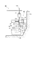
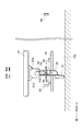
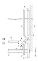
図1は、第1実施形態に係る堆積物の掻寄装置を示す正面模式図、図2は、第1実施形態に係る堆積物の掻寄装置を示す側面模式図である。
【0025】
本実施形態の堆積物の掻寄装置1は、図1に示すように、槽10の底面10bに堆積する汚泥等の堆積物を汚泥ピット10aに向けて掻き寄せるものであって、堆積物を掻き寄るフライト(掻寄羽根)12が水平方向にかつ汚泥ピット10aに接離する方向に複数配設された梯子状の掻寄架台20と、この掻寄架台20を槽10の底面10bに対して略平行で汚泥ピット10aに接離する方向に往復運動させる駆動装置(駆動手段)50と、を備えている。
【0026】
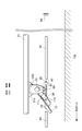
掻寄架台20は、図1及び図2に示すように、この掻寄架台20の往復方向に延在する2本の平行な駆動方向材21と、この2本の駆動方向材21に対して垂直に交差して配置されると共に互いに所定間隔離間された複数の平行材22と、を備えている。平行材22と駆動方向材21とは、図3に示すように、平行材22に固定された結合板22aと、駆動方向材21に固定された結合板21aと、がネジ固定されることによって接続され、梯子型の形状をなしている。
【0027】
この平行材22の両端には、図2〜図4に示すように、この平行材22の軸周りに回転可能なローラ24が各々設置されている。また、この平行材22は、図2に示すように、この平行材22の軸回りに揺動可能とされたアーム(掻寄羽根支持手段)25を、この平行材22の軸方向に離間して2つ備えている。各アーム25の先端部には、図1〜図5に示すように、平行材22の軸方向に延在し、この槽10の底面10bに堆積した堆積物を掻き寄せるフライト(掻寄羽根)12が設置されている。
【0028】
そして、上述の結合板22aは、図3及び図5に示すように、フライト12が平行材22のほぼ鉛直下方に垂下する第一揺動位置よりも復動方向側(図5の図示右側)へ揺動しないようにすべく、アーム25の揺動を制限する突起としてのアームストッパ(掻寄羽根揺動制限部材)26を備えている。
【0029】
図1に示すように、往復方向に隣接する3つのアーム25同士は、これらアーム25の揺動動作を連動すべく連結部材60によって連結されている。この連結部材60は、駆動方向材21の軸方向に延在し、図3に示すように、各々のアーム25に対してピン61で回動自在に連結されている。
【0030】
駆動装置50は、図1〜図4に示すように、掻寄架台20を水平方向に移動可能に支持するガイドレール82を有している。ガイドレール82は、図2に示すように、樋状断面を有して掻寄架台20の往復方向に延在し、槽10で互いに対向する側壁10c,10c上に、槽10の底面10bに平行に、かつ、樋の開口側が各々掻寄架台20側を向くように設置されている。そして、このガイドレール82は、掻寄架台20の平行材22の両端のローラ24をこのガイドレール82内に各々常時収容している。
【0031】
このガイドレール82の底面10bからの高さは、図3及び図5に示すように、掻寄架台20のアーム25が第一揺動位置にあるときに、フライト12の下端がほぼ槽10の底面10bに達する高さとされている。そして、ガイドレール82は、掻寄架台20を槽10の底面10bと平行な往復運動をするように案内する。
【0032】
また、駆動装置50は、図1及び図2に示すように、正逆方向に回転可能な駆動モータ51と、この駆動モータ51による駆動力を伝達するチェーン52と、チェーン52を介して駆動され掻寄架台20の往復方向と垂直な水平軸回りに正逆回転されるように槽10側に支持されるスプロケット(歯車)103と、駆動方向材21に固定部材102を介して曲折不能に固定され掻寄架台20の往復方向に延在してスプロケット103と噛合するチェーン(噛合部材)101とを備えており、ガイドレール82によって支持される掻寄架台20を図示左右方向に往復運動させる。
【0033】
なお、このような駆動方式は、ピンギア方式と呼ばれ、掻寄架台20やチェーン101等の据え付け等の精度があまり要求されず設置やメンテナンスが容易とされ、堆積物等の夾雑物を含む水中での駆動に適している。また、従来のチェーンフライト式の掻寄装置と比較して回転部や摺動部が少ないために所用動力が少なくてすみ、さらに、チェーンやスプロケット、シューなどの摩耗部材が少なく、構造がシンプルであって低コスト化が可能となっている。さらに、往復方向に延在する長いチェーンがないため、チェーンはずれ等の問題が低減されて掻寄装置1の信頼性を高めることができると共に、長いチェーンの遊びを調節するタイトナ等も不要とされ低コスト化が可能となる。
【0034】
そして、本実施形態の掻寄装置1は、図1に示すように、掻寄架台20の位置に応じてフライト12を揺動動作させるためのカムプレート(カム部材)87と、カムプレート87を回動させるホールドピン(当接部材)83及びリセットピン(当接部材)84とを備えている。これらのカムプレート87、ホールドピン83、リセットピン84は、互いに連結された3つのアーム25の内の一つに対して一組設けられている。
【0035】
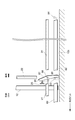
ホールドピン83及びリセットピン84は、図1〜図5に示すように、各々上下に延びる棒状部材であり、ガイドレール82の下方で掻寄架台20の往復方向に互いに離間して一組設置され、往動方向側がホールドピン83、復動方向側がリセットピン84とされている。これらホールドピン83及びリセットピン84は、図3に示すように各々ステー85を介して側壁10cに固定されている。ホールドピン83及びリセットピン84の側壁10cからの距離は、図4に示すように、ほぼ同等とされている。
【0036】
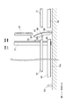
カムプレート87は、図4に示すように一端部89及び他端部90を有する細長い板状をなし、図3及び図5に示すように、カムプレートサポート108に支持されている。このカムプレートサポート108は、垂直下方に延在する回動軸88を備えると共に、平行材22の下側でアーム25よりも外側の部分に設置されており、カムプレート87の略中央部分をこの回動軸88によって回動自在に支持する。
【0037】
そして、図4及び図5に示すように、フライト12が平行材22のほぼ垂直下方に垂下する第一揺動位置にある場合に、カムプレート87の一端部89は、ホールドピン83とリセットピン84との間に位置するようにされる一方、カムプレート87の他端部90は、アーム25よりも復動方向側に位置するようにされている。
【0038】
また、フライト12が第一揺動位置とされる場合に、アーム25で、カムプレート87の他端部90と対向する部分には、当該部分及び当該部分よりもやや下部を覆ってアーム25を補強する補強材110が設置されている。補強材110で、カムプレートの他端部90と対向する部分よりもやや下部には、図5に示すように、カムプレート87の他端部90の先端と係合可能な凹部(係合部)111が形成されている。
【0039】
次に、このような堆積物の掻寄装置1の作用について説明する。
【0040】
まず、図4及び図5に示すように、フライト12が平行材22からほぼ垂直下方に垂下する第一揺動位置に位置し、槽10の底に沈殿した堆積物を掻き寄せ可能な状態から説明する。なお、図4及び図5に示されるフライト12の往動方向側及び復動方向側には、連結部材60を介して当該フライト12と連動して揺動動作されるアーム25及びフライト12の組が1つづつあるが、これ以降の図4〜図12では図示を省略する。
【0041】
まず、この状態から、駆動モータ51によって掻寄架台20を白矢印方向(図示左側)、すなわち、汚泥ピット10a方向に向かって動かす(往動)。これにより、各々のフライト12によって堆積物が汚泥ピット10a方向に掻き寄せられ、堆積物が汚泥ピット10a内に送られる。
【0042】
なお、フライト12が堆積物を掻き寄せる際、アーム25は、堆積物等から図示反時計回り(図5参照)のモーメントを受けるが、アームストッパ26によってアーム25のこれ以上の図示反時計方向への揺動が規制されているので、堆積物の掻き寄せが確実に可能とされている。
【0043】
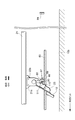
このような掻き寄せを続けて掻寄架台20が往動方向側に進むと、図6及び図7に示すように、カムプレート87の一端部89が往動方向側にあるホールドピン83に当接し、カムプレート87は回動軸88を中心に、上から見て(図6参照)反時計方向に回動し、他端部90は補強材110を介してアーム25を往動方向向きに押圧し、フライト12は、平行材22を中心に往動方向側へ揺動される。ここで、図7に示すように、アーム25が上方に揺動されるにつれ、補強材110でカムプレート87の他端部90が当接する部分は下側にずれて凹部111に近づくことになる。また、図7のアーム25の往復方向に隣接する2つのアーム25(不図示)も連結部材60を介して揺動される。
【0044】
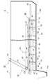
そして、図8及び図9に示すように、掻寄架台20が往動方向側へさらに進んでカムプレート87がさらに回動されると、フライト12がより上方にまで揺動され、カムプレート87の他端部90の先端がアーム25の補強材110の凹部111と係合し、アーム25およびフライト12の重量をカムプレート87の上面が受けるようになる。このときのフライト12の揺動位置を第二揺動位置と呼ぶ。これによって、図9に示すように、第一揺動位置に対してフライト12が汚泥ピット10a側に図示時計回りに十分に傾くこととなり、フライト12が槽10の底10bから所定の距離離間されることとなる。
【0045】
この状態まで掻寄架台20が往動すると、図示しないロータリーエンコーダ又は近接スイッチがこれを検知して、駆動モータ51は逆回転を始める。これにより、掻寄架台20の黒矢印方向への移動が開始され、図10に示すように、フライト12が槽10の底部から離間された状態で掻寄架台20を元の位置に復帰させる復動がなされる。この時、フライト12が槽10の底部から離間されているので、往動時に掻き寄せた堆積物を往動方向側へ戻したり巻き上げたりすることがなくされている。
【0046】
また、この復動動作の際、カムプレート87の一端部89とホールドピン83との当接は解除されるが、カムプレート87と補強材110の凹部111とが係合し、フライト12やアーム25の自重がカムプレート87の板厚方向に伝わって回転方向にはほとんど伝わらないため、フライト12等の自重によってフライト12が下方に揺動して第一揺動位置に戻ることが確実に防止されている。
【0047】
このようにして、掻寄架台20が復動を続けると、図11に示すように、カムプレート87の一端部89がリセットピン84に当接し、カムプレート87は、回動軸88を中心に上から見て時計回りに回動する。これにより、補強材110の凹部111とカムプレート87の他端部90の先端との係合が解除され、カムプレート87の回動に従ってフライト12が第二揺動位置から自重によって下方に揺動する。
【0048】
そして、図12に示すように、さらに掻寄架台20が復動を続けてカムプレート87がさらに回動すると、フライト12は第一揺動位置に復帰し、アーム25の補強材110とカムプレート87の他端部90との当接が解除される。
【0049】
この状態まで掻寄架台20の復動が進むと図示しないロータリーエンコーダ又は近接スイッチがこれを検知し、駆動モータ51は再び正回転を始める。これにより、掻寄架台20が白矢印方向に再び移動され、第一揺動位置とされたフライト12により、堆積物の汚泥ピット10a方向への掻き寄せが可能となる。
【0050】
そして、このような往動と復動の一連の動作を繰り返すことにより、復動時に堆積物を逆方向に戻すことや巻き上げることを防止しつつ、堆積物を効率よく汚泥ピット10aに掻き寄せることが可能となっている。
【0051】
また、往復方向に並設された複数のフライト12がこの一連の動作によって揺動されるので、堆積物が複数のフライト12によって分担して往動側に掻き寄せられ、一つのフライト12で槽10の全長の掻き寄せを行う場合に比して掻寄架台20の往復運動の距離が短くなっている。このため、一つのフライト12で掻き寄せを行う場合に比して、効率よく掻き寄せが行える。
【0052】
また、隣接する3つのフライト12の内の一つのフライト12が直接カムプレート87よって揺動され、このフライト12に隣接する他の2つのフライト12は連結部材60によって連動して揺動されるので、カムプレート87やホールドピン83やリセットピン84の数をフライト12の数に比して少なくできるので、構成が複雑化せず、コストが低く抑えられる。
【0053】
さらに、本実施形態の掻寄装置1は、汚泥ピット10a等の洗浄が容易に行えると共に、上水道用の槽等においては薬品沈殿の効率を高める傾斜板の設置も容易とされ、さらに、設置に際して、パイプスキーマーなどの設置場所の制約を受けず、駆動部の位置が自由に設定でき、既存の槽の筐体に少ないはつり箇所で容易に設置できるという特徴を有している。
【0054】
次に、図13を参照して、第2実施形態に係る堆積物の掻寄装置2について説明する。
【0055】
本実施形態の堆積物の掻寄装置2が第1実施形態の掻寄装置1と異なる点は、駆動装置50が、チェーン101及び固定部材102に代えて、掻寄架台20の往復方向に延在しスプロケット103の正逆回転運動を往復運動に変換するように掛け渡されるチェーン53と、チェーン53と駆動方向材21とを固定しチェーン53の往復運動を掻寄架台20に伝達させる固定板55と、チェーン53のたるみ等を調節するタイトナ54と、を備えている点である。
【0056】
この掻寄装置1によっても、スプロケット103の正逆転に応じて、掻寄架台20が駆動方向材21の延在方向に好適に往復駆動され、上記実施形態と同様に好適な堆積物の掻き寄せがなされる。
【0057】
なお、本発明に係る堆積物の掻寄装置は、上記実施形態に限定されるものではなく、種々の変形態様をとることが可能である。
【0058】
例えば、上記実施形態では、復動時にアーム25を第二揺動位置に確実に維持すべく、補強材110に、カムプレート87の他端部90の先端と係合する凹部111が形成されているが、これに限られない。例えば、凸部等でもよく、要は、他端部90と係合してフライト12を第二揺動位置にとどめさせることが可能であればよい。また、カムプレート87の回動軸88から他端までの距離が十分長くアームの揺動角度が大きくなってフライト10やアーム25がカムプレート87に乗ってしまう場合等、カムプレート87の他端部90がアーム25等と係合しなくても復動時にフライト12が第二揺動位置を維持できる場合には、凹部111等を形成しなくても構わない。
【0059】
また、上記実施形態では、カムプレート87の他端部90がアーム25に当接することによりフライト12を揺動させているが、アーム25が短い場合等には、他端部90が直接フライト12に当接してこれを揺動させてもよい。
【0060】
また、上記実施形態では、カムプレート87は、アーム25で平行材(水平軸)22より下方の部分に当接することにより、フライト12を往動方向側に揺動させているが、アーム25で平行材22より上方の部分に当接してフライト12を復動方向側に揺動させてもよい。
【0061】
また、上記実施形態では、カムプレート87は、掻寄架台20に対して、掻寄架台20の往復方向に直交する垂直軸回りに回動可能に支持されているが、掻寄架台20の往復方向に直交する水平軸回りに回動可能に支持されてもよい。この場合は、例えば、ホールドピン83やリセットピン84をガイドレール82よりも上方に配置し、往動時にカムプレート87の上側の一端部がホールドピン83と当接して回動されて、カムプレート87の他端部が平行材22より下方のアーム25等に当接してフライト12を揺動させるようにすればよい。また、カムプレート87の形状も特に限定されず、ホールドピン83やリセットピン84と当接することによりフライト12を揺動させるものであればよい。
【0062】
また、上記実施形態の掻寄装置1は、槽10に沈殿する汚泥を掻き寄せているが、槽の底部に堆積する堆積物であればこれに限られず、例えば粉体等でもよい。
【0063】
【発明の効果】
本発明の堆積物の掻寄装置では、掻寄架台が往動する過程において、往動方向側の当接部材と当接するカム部材によって掻寄羽根が上方に揺動される一方、掻寄架台が復動する過程において、復動方向側の当接部材と当接するカム部材によって掻寄羽根が下方に復帰可能とされる。
【0064】
このため、カム部材が復動方向側の当接部材と当接して掻寄羽根が往動位置としての第一揺動位置に復帰してからカム部材が往動方向側の当接部材と当接して掻寄羽根が復動位置としての第二揺動位置とされるまでの往動過程で、掻寄羽根が層の底に近接することとなるので層底部の堆積物の往動方向側への掻き寄せが可能となる。一方、カム部材が往動方向側の当接部材と当接して掻寄羽根が第二揺動位置とされてからカム部材が復動方向側の当接部材と当接して掻寄羽根が第一揺動位置に復帰するまでの復動過程では、掻寄羽根が槽の底から離間されるので、往動時に掻き寄せた堆積物との接触や堆積物の巻き上げ等が確実に防止される。このため、効率的に堆積物を掻き寄せることが可能な堆積物の掻寄装置が提供される。
【図面の簡単な説明】
【図1】第1実施形態に係る堆積物の掻寄装置の正面模式図である。
【図2】図1の掻寄装置の側面模式図である。
【図3】図2中のA部の拡大図である。
【図4】図3を上から見た一部破断模式図である。
【図5】図4の正面模式図である。
【図6】図4の状態から、掻寄架台が往動方向に進んでカムプレートがホールドピンに当接した状態を示す一部破断模式図である。
【図7】図6の正面模式図である。
【図8】図6の状態から、掻寄架台がさらに往動方向に進んだ状態を示す一部破断模式図である。
【図9】図8の正面模式図である。
【図10】図8の状態から、掻寄架台が復動方向に進んだ状態を示す模式図である。
【図11】図10の状態から、掻寄架台がさらに復動方向に進んでカムプレートがリセットピンに当接した状態を示す模式図である。
【図12】図11の状態から、掻寄架台がさらに復動方向に進んだ状態を示す模式図である。
【図13】第二実施形態に係る堆積物の掻寄装置の正面模式図である。
【符号の説明】
1,2…堆積物の掻寄装置、10…槽、12…フライト(掻寄羽根)、20…掻寄架台、25…アーム(掻寄羽根支持手段)、26…アームストッパ(掻寄羽根揺動制限部材)、50…駆動装置(駆動手段)、60…連結部材、83…ホールドピン(当接部材)、84…リセットピン(当接部材)、87…カムプレート(カム部材)、89…一端部、90…他端部、101…チェーン(噛合部材)、103…スプロケット(歯車)、111…凹部(係合部)。[0001]
BACKGROUND OF THE INVENTION
The present invention relates to a deposit scraping device that scrapes deposits deposited on the bottom of a tank.
[0002]
[Prior art]
Conventionally, as a scraping device for deposits deposited on the bottom of a tank such as a sedimentation basin, a ladder-like scraping stand in which a plurality of flights (scraping blades) for scraping the deposits are arranged horizontally is arranged at the bottom of the tank. There is known a so-called reciprocating type scraping device that reciprocates with a cylinder.
[0003]
In such a reciprocating type scraping device, when the scraping base is moved forward and the deposit is scraped to one side by flight, the scraping base is moved back and returned to the original position again. It is necessary to prevent the flight from returning to the original position the deposits that have been scraped during the forward movement.
[0004]
Therefore, in the conventional reciprocating type scraping device, the flight is wedge-shaped and the deposit is scraped to one side at the vertical plane of this flight when the scraping base moves forward, while at the time of backward movement than during the forward movement A wedge-type reciprocating type scraping device that drives the scraping table in the reverse direction at a high speed so that the scraped-up deposits get over the slope of the flight and prevent the deposits from returning (see, for example, Patent Document 1) ), Or when the backward movement is lifted from the outer side of the tank, the scraping base is tilted downward from the forward movement direction toward the backward movement direction. An inclined reciprocating type scraper (see, for example, Patent Document 2) that prevents the flight on the forward direction side of the platform from returning deposits that are scraped during the forward movement is known.
[0005]
[Patent Document 1]
JP-A-11-137912
[Patent Document 2]
JP 2000-354705 A
[0006]
[Problems to be solved by the invention]
However, in the wedge-type reciprocating type scraping device, when the scraping table is moved back, the deposits often do not get over the slope of the flight and often return or roll up. Even in the type scraping device, in particular, the flight on the backward movement side of the scraping table often returns or winds up the deposit, and the deposit cannot be scraped efficiently.
[0007]
The present invention has been made in view of the above problems, and provides a deposit scraping device capable of scraping deposits efficiently without causing return of the deposits or winding up. Objective.
[0008]
[Means for Solving the Problems]
The deposit scraping device according to the present invention is a deposit scraping device that moves the scraping blade along the bottom of the tank and scrapes the deposit deposited on the bottom of the tank. A scraping blade support means that swings around a horizontal axis perpendicular to the moving direction of the scraping blade, a scraping base on which the scraping blade support means is installed, and the scraping base parallel to the bottom of the tank Drive means for reciprocating movement, a pair of abutting members installed in the tank and spaced apart in the reciprocating direction of the cradle, and supported by the cradle, and in the process of moving the cradle, By contacting the contact member, the scraping blade is swung upward from the first swing position as the forward movement position located below the horizontal axis to be the second swing position as the backward movement position. In the process of moving the platform backward, the scraping blade is brought into contact with the contact member on the backward movement side. Forward movement And a cam member capable of returning to the first swing position as a position.
[0009]
According to the deposit scraping device of the present invention, when the scraping base moves forward, the scraping blade swings upward from the first swing position by the cam member that contacts the contact member on the forward movement side. On the other hand, when the scraper is moved backward, the scraping blade is swung from the second swing position by the cam member that contacts the contact member on the backward movement side. It is possible to return to the position.
[0010]
Therefore, after the cam member comes into contact with the contact member on the backward direction side and the scraping blade returns to the first swing position, the cam member comes into contact with the contact member on the forward direction side and the scraping blade In the forward movement process until the second swing position is reached, the scraping blade comes close to the bottom of the tank, so that the sediment at the bottom of the layer can be scraped toward the forward movement side. On the other hand, after the cam member comes into contact with the abutting member on the forward direction side and the scraping blade is in the second swing position, the cam member comes into contact with the abutting member on the backward direction side and the scraping blade comes into first position. In the backward movement process until returning to one swinging position, the scraping blade is separated from the bottom of the tank, so that it is possible to prevent contact with the deposit that has been squeezed at the time of forward movement, roll-up of the deposit, and the like.
[0011]
Here, the cam member is supported by the scraping base so as to be rotatable about an axis perpendicular to the reciprocating direction between the one end and the other end, and the one end of the cam member moves forward in the process of moving the scraping base. The second end swings by rotating in contact with the contact member on the direction side and the other end abutting on the scraping blade or the scraping blade support means and swinging the scraping blade upward from the first swing position. In the process of moving the scraping table backward, one end part is brought into contact with the abutting member on the returning direction side and rotated in the reverse direction to return the scraping blade to the first swing position. It is preferable that
[0012]
According to this, during the forward movement of the scraping base, the scraping blade is swung upward from the first swinging position by the rotation of the cam member due to the contact with the contact member on the forward movement side. On the other hand, when the scraping base is moved backward, the scraping blade is rotated in the reverse direction by the contact with the contact member on the backward movement side so that the scraping blade is moved to the second swing position. To the first swing position so that the scraping blade can be swung suitably.
[0013]
Here, the scraping blade or the scraping blade support means is engaged with the other end portion of the cam member when the scraping blade is swung to the second swinging position, and the scraping blade is moved to the second swinging position. It is preferable that an engaging portion that is kept in the moving position is formed.
[0014]
According to this, when the scraping blade is swung to the second swing position, the other end portion of the cam member and the scraping blade or the scraping blade supporting means that comes into contact with the other end portion are engaged. Therefore, even if the contact between the cam member and the contact member on the forward direction side is released when the scraping base moves backward after the scraping blade is swung to the second swing position, The scraping blade is reliably maintained at the second swing position.
[0015]
Further, the second swing position is set to the forward direction side relative to the first swing position, and is installed on the scraping base to restrict the scraping blade from swinging from the first swing position to the backward direction side. It is preferable to limit the provision of the scraping blade swing limiting member.
[0016]
As a result, during the forward movement, even if the scraping blade receives a force in the backward movement direction due to deposits or the like, it does not rock in the backward movement direction from the first rocking position. Made. Further, since the second swing position is on the forward movement side with respect to the first swing position, the scraping blade swing restricting member does not hinder the swinging motion of the scraping blade by the cam member.
[0017]
Further, it is preferable that a plurality of combinations of the scraping blades and the scraping blade support means for supporting the scraping blades are provided, and a plurality of the scraping blade support means are juxtaposed in the reciprocating direction with respect to the scraping stand.
[0018]
When a plurality of flights are provided in this way, each flight can be swung by the above-described series of operations, and the deposit is shared by the plurality of flights and scraped to the forward direction side. For this reason, compared with the case where the entire tank length is scraped by one flight, the distance of the reciprocating motion of the scraping base is shortened, and more efficient scraping is possible.
[0019]
Further, it is preferable that a connecting means for interlocking the swinging movements of the scraping blades is provided, and the cam member and the abutting member are provided for at least one of the combinations.
[0020]
According to this, at least one scraping blade of the combination is swung by the cam member, and in conjunction with this, the scraping blade according to the other combination is also swung by the connecting means. For this reason, since the number of cam members and contact members can be reduced as compared with the number of combinations, the configuration is not complicated and the cost can be kept low.
[0021]
The driving means includes a gear that is rotated forward and backward about an axis perpendicular to the reciprocating direction of the scraping table, a gear that extends in the reciprocating direction of the scratching table and is fixed to the scratching table so as not to be bent. It is preferable to include a meshing member capable of meshing.
[0022]
According to this, installation and maintenance can be facilitated, and the scraper can be reciprocated simply and preferably.
[0023]
DETAILED DESCRIPTION OF THE INVENTION
DESCRIPTION OF EXEMPLARY EMBODIMENTS Hereinafter, preferred embodiments of a deposit scraping apparatus according to the invention will be described in detail with reference to the accompanying drawings. In the description of the drawings, the same or corresponding elements are denoted by the same reference numerals, and redundant description is omitted.
[0024]
FIG. 1 is a schematic front view showing a deposit scratching apparatus according to the first embodiment, and FIG. 2 is a schematic side view showing the deposit scratching apparatus according to the first embodiment.
[0025]
As shown in FIG. 1, the
[0026]
As shown in FIG. 1 and FIG. 2, the
[0027]
As shown in FIGS. 2 to 4,
[0028]
As shown in FIGS. 3 and 5, the above-described
[0029]
As shown in FIG. 1, the three
[0030]
As shown in FIGS. 1 to 4, the driving
[0031]
As shown in FIGS. 3 and 5, the height of the
[0032]
Further, as shown in FIGS. 1 and 2, the
[0033]
Such a drive system is called a pin gear system, and is not required to be highly accurate, such as installation of the
[0034]
As shown in FIG. 1, the
[0035]
As shown in FIGS. 1 to 5, each of the
[0036]
The
[0037]
4 and 5, when the
[0038]
Further, when the
[0039]
Next, the operation of the
[0040]
First, as shown in FIGS. 4 and 5, the
[0041]
First, from this state, the
[0042]
When the
[0043]
When the
[0044]
As shown in FIGS. 8 and 9, when the
[0045]
When the
[0046]
Further, at the time of this backward movement, the contact between the one
[0047]
In this way, when the
[0048]
Then, as shown in FIG. 12, when the
[0049]
When the return movement of the
[0050]
Then, by repeating such a series of forward and backward movements, the deposits are efficiently scraped to the
[0051]
In addition, since the plurality of
[0052]
In addition, one of the three
[0053]
Furthermore, the
[0054]
Next, with reference to FIG. 13, the scraping scraping apparatus 2 according to the second embodiment will be described.
[0055]
The deposit scraping device 2 of the present embodiment is different from the
[0056]
Also with this
[0057]
In addition, the scraping device according to the present invention is not limited to the above-described embodiment, and can be variously modified.
[0058]
For example, in the above embodiment, the reinforcing
[0059]
In the above embodiment, the
[0060]
Further, in the above-described embodiment, the
[0061]
In the above-described embodiment, the
[0062]
Moreover, although the
[0063]
【The invention's effect】
In the deposit scraping device of the present invention, in the process in which the scraping base moves forward, the scraping blade is swung upward by the cam member that contacts the abutting member on the forward direction side. In the process of returning, the scraping blade can be returned downward by the cam member that comes into contact with the contact member on the return direction side.
[0064]
For this reason, after the cam member comes into contact with the contact member on the backward movement direction and the scraping blade returns to the first swing position as the forward movement position, the cam member contacts the contact member on the forward movement direction side. In the forward movement process until the scraping blade comes into contact with the second swinging position as the backward movement position, the scraping blade comes close to the bottom of the layer, so the forward direction side of the sediment at the bottom of the layer It is possible to rake it up. On the other hand, after the cam member comes into contact with the abutting member on the forward direction side and the scraping blade is in the second swing position, the cam member comes into contact with the abutting member on the backward direction side and the scraping blade comes into first position. In the backward movement process until it returns to one swinging position, the scraping blade is separated from the bottom of the tank, so that contact with the deposits scraped up during the forward movement, roll-up of the deposits, etc. are surely prevented. . For this reason, the deposit scraping apparatus which can scrape a deposit efficiently is provided.
[Brief description of the drawings]
FIG. 1 is a schematic front view of a deposit scraping apparatus according to a first embodiment.
FIG. 2 is a schematic side view of the scraping device of FIG. 1;
FIG. 3 is an enlarged view of a portion A in FIG.
FIG. 4 is a partially broken schematic view of FIG. 3 as viewed from above.
FIG. 5 is a schematic front view of FIG. 4;
6 is a partially broken schematic view showing a state in which the scraping base has advanced in the forward movement direction and the cam plate is in contact with the hold pin from the state of FIG. 4; FIG.
7 is a schematic front view of FIG. 6. FIG.
FIG. 8 is a partially broken schematic view showing a state where the scraping base further advances in the forward movement direction from the state of FIG. 6;
9 is a schematic front view of FIG. 8. FIG.
10 is a schematic diagram showing a state in which the scraping base has advanced in the backward movement direction from the state of FIG. 8. FIG.
11 is a schematic view showing a state where the scraping base further advances in the backward movement direction from the state of FIG. 10 and the cam plate is in contact with the reset pin.
12 is a schematic view showing a state in which the scraper has further advanced in the backward movement direction from the state of FIG. 11. FIG.
FIG. 13 is a schematic front view of a deposit scraping device according to a second embodiment.
[Explanation of symbols]
DESCRIPTION OF
Claims (7)
前記掻寄羽根を前記掻寄羽根の前記移動方向と直交する水平軸周りに揺動自在に支持する掻寄羽根支持手段と、
前記掻寄羽根支持手段が設置される掻寄架台と、
前記掻寄架台を前記槽の底に平行に往復運動させる駆動手段と、
前記槽に設置され前記掻寄架台の往復方向に離間された一対の当接部材と、
前記掻寄架台に支持され、前記掻寄架台が往動する過程で往動方向側の前記当接部材と当接することにより前記掻寄羽根を前記水平軸の下方に位置する往動位置としての第一揺動位置から上方に揺動させて復動位置としての第二揺動位置とすると共に、前記掻寄架台が復動する過程で復動方向側の前記当接部材と当接することにより前記掻寄羽根を前記往動位置としての前記第一揺動位置に復帰可能とするカム部材と、
を備え、
前記カム部材は、一端部と他端部との間が前記往復方向に直交する軸回りに回動自在に前記掻寄架台に支持され、前記掻寄架台が往動する過程で前記一端部が往動方向側の前記当接部材と当接して回動され前記他端部が前記掻寄羽根又は前記掻寄羽根支持手段に当接して前記掻寄羽根を前記第一揺動位置から上方に揺動させて前記第二揺動位置とすると共に、前記掻寄架台が復動する過程で前記一端部が復動方向側の前記当接部材と当接して前記回動と逆方向に回動され前記掻寄羽根を前記第一揺動位置に復帰可能とすることを特徴とする、堆積物の掻寄装置。A scraping device for deposits that moves the scraping blade along the bottom of the tank and scrapes the deposits deposited on the bottom of the tank,
Scraping blade support means for swingably supporting the scraping blade around a horizontal axis perpendicular to the moving direction of the scraping blade;
A scraping stand on which the scraping blade support means is installed;
Drive means for reciprocating the scraper in parallel with the bottom of the tank;
A pair of abutting members installed in the tank and spaced apart in the reciprocating direction of the scraper;
As the forward movement position where the scraping blade is positioned below the horizontal axis by being in contact with the contact member on the forward direction side in the process of being supported by the scraping base and moving forward. By swinging upward from the first swing position to a second swing position as a return position, and in contact with the contact member on the return direction side in the process of returning the scraping base A cam member capable of returning the scraping blade to the first swing position as the forward movement position;
Equipped with a,
The cam member is supported by the scraper so as to be rotatable about an axis orthogonal to the reciprocating direction between one end and the other end, and the one end is in the process of moving the scraper forward. The other end is brought into contact with the scraping blade or the scraping blade support means so that the scraping blade is moved upward from the first swing position. Swing to the second swing position, and in the process of returning the scraping table, the one end contacts the contact member on the return direction side and rotates in the opposite direction to the rotation. And the scraping blade is capable of returning to the first swing position .
Priority Applications (1)
| Application Number | Priority Date | Filing Date | Title |
|---|---|---|---|
| JP2002297705A JP3909005B2 (en) | 2002-10-10 | 2002-10-10 | Sediment scraping device |
Applications Claiming Priority (1)
| Application Number | Priority Date | Filing Date | Title |
|---|---|---|---|
| JP2002297705A JP3909005B2 (en) | 2002-10-10 | 2002-10-10 | Sediment scraping device |
Publications (2)
| Publication Number | Publication Date |
|---|---|
| JP2004130228A JP2004130228A (en) | 2004-04-30 |
| JP3909005B2 true JP3909005B2 (en) | 2007-04-25 |
Family
ID=32287338
Family Applications (1)
| Application Number | Title | Priority Date | Filing Date |
|---|---|---|---|
| JP2002297705A Expired - Fee Related JP3909005B2 (en) | 2002-10-10 | 2002-10-10 | Sediment scraping device |
Country Status (1)
| Country | Link |
|---|---|
| JP (1) | JP3909005B2 (en) |
Families Citing this family (4)
| Publication number | Priority date | Publication date | Assignee | Title |
|---|---|---|---|---|
| JP4099162B2 (en) * | 2004-06-04 | 2008-06-11 | 住友重機械エンバイロメント株式会社 | Method of detecting malfunction of deposit scraping device and malfunction detection device of deposit scraping device |
| JP4629004B2 (en) * | 2006-07-18 | 2011-02-09 | 住友重機械エンバイロメント株式会社 | Scraping device |
| JP4633705B2 (en) * | 2006-11-01 | 2011-02-16 | 住友重機械エンバイロメント株式会社 | Sludge scraping device |
| CN113911627B (en) * | 2021-08-30 | 2023-09-01 | 华能秦煤瑞金发电有限责任公司 | Efficient weighing coal feeder |
-
2002
- 2002-10-10 JP JP2002297705A patent/JP3909005B2/en not_active Expired - Fee Related
Also Published As
| Publication number | Publication date |
|---|---|
| JP2004130228A (en) | 2004-04-30 |
Similar Documents
| Publication | Publication Date | Title |
|---|---|---|
| US5098561A (en) | Machine for intercepting solid constituents in liquid streams | |
| JP3909005B2 (en) | Sediment scraping device | |
| JP3315682B2 (en) | Sludge scraper | |
| JP2003326108A (en) | Sedimentation apparatus | |
| JP3746023B2 (en) | Sediment scraping device | |
| JP4069098B2 (en) | Sediment scraping device | |
| JP3018161U (en) | Sludge attracting device | |
| JP2008073599A (en) | Scraping device for accumulated matter and floating-up matter | |
| JP3735746B2 (en) | Suspended scraping device | |
| JP6058509B2 (en) | Sludge scraping machine | |
| JP4099162B2 (en) | Method of detecting malfunction of deposit scraping device and malfunction detection device of deposit scraping device | |
| JP2019136618A (en) | Sludge scraping device | |
| JP2601286Y2 (en) | Sludge scraper | |
| JP4088614B2 (en) | Sludge recovery equipment | |
| JP4633707B2 (en) | Scraping device | |
| JP4146702B2 (en) | Floating object scraping device | |
| KR101775992B1 (en) | Sand Remover having Sand Removing Efficiency Increasing Bucket | |
| CN120515151B (en) | A treatment device based on the drainage system of a building | |
| JP2006095415A (en) | Recovery apparatus of sludge, or the like | |
| JP4629004B2 (en) | Scraping device | |
| JP4584887B2 (en) | Sludge scraping device | |
| JP2008229524A (en) | Scum skimmer drive unit for sludge scraper | |
| JP2002273107A (en) | Dust extractor | |
| SU1360896A2 (en) | Arrangement for removing oxide film | |
| JPH0447226Y2 (en) |
Legal Events
| Date | Code | Title | Description |
|---|---|---|---|
| A621 | Written request for application examination |
Free format text: JAPANESE INTERMEDIATE CODE: A621 Effective date: 20041110 |
|
| A977 | Report on retrieval |
Free format text: JAPANESE INTERMEDIATE CODE: A971007 Effective date: 20060804 |
|
| A131 | Notification of reasons for refusal |
Free format text: JAPANESE INTERMEDIATE CODE: A131 Effective date: 20060815 |
|
| A521 | Written amendment |
Free format text: JAPANESE INTERMEDIATE CODE: A523 Effective date: 20061005 |
|
| TRDD | Decision of grant or rejection written | ||
| A01 | Written decision to grant a patent or to grant a registration (utility model) |
Free format text: JAPANESE INTERMEDIATE CODE: A01 Effective date: 20070116 |
|
| A61 | First payment of annual fees (during grant procedure) |
Free format text: JAPANESE INTERMEDIATE CODE: A61 Effective date: 20070119 |
|
| R150 | Certificate of patent or registration of utility model |
Free format text: JAPANESE INTERMEDIATE CODE: R150 |
|
| S111 | Request for change of ownership or part of ownership |
Free format text: JAPANESE INTERMEDIATE CODE: R313111 |
|
| FPAY | Renewal fee payment (event date is renewal date of database) |
Free format text: PAYMENT UNTIL: 20100126 Year of fee payment: 3 |
|
| R350 | Written notification of registration of transfer |
Free format text: JAPANESE INTERMEDIATE CODE: R350 |
|
| FPAY | Renewal fee payment (event date is renewal date of database) |
Free format text: PAYMENT UNTIL: 20110126 Year of fee payment: 4 |
|
| FPAY | Renewal fee payment (event date is renewal date of database) |
Free format text: PAYMENT UNTIL: 20120126 Year of fee payment: 5 |
|
| S531 | Written request for registration of change of domicile |
Free format text: JAPANESE INTERMEDIATE CODE: R313531 |
|
| FPAY | Renewal fee payment (event date is renewal date of database) |
Free format text: PAYMENT UNTIL: 20120126 Year of fee payment: 5 |
|
| R350 | Written notification of registration of transfer |
Free format text: JAPANESE INTERMEDIATE CODE: R350 |
|
| FPAY | Renewal fee payment (event date is renewal date of database) |
Free format text: PAYMENT UNTIL: 20130126 Year of fee payment: 6 |
|
| FPAY | Renewal fee payment (event date is renewal date of database) |
Free format text: PAYMENT UNTIL: 20130126 Year of fee payment: 6 |
|
| R250 | Receipt of annual fees |
Free format text: JAPANESE INTERMEDIATE CODE: R250 |
|
| S802 | Written request for registration of partial abandonment of right |
Free format text: JAPANESE INTERMEDIATE CODE: R311802 |
|
| R350 | Written notification of registration of transfer |
Free format text: JAPANESE INTERMEDIATE CODE: R350 |
|
| LAPS | Cancellation because of no payment of annual fees |