JP3746023B2 - Sediment scraping device - Google Patents
Sediment scraping device Download PDFInfo
- Publication number
- JP3746023B2 JP3746023B2 JP2002192451A JP2002192451A JP3746023B2 JP 3746023 B2 JP3746023 B2 JP 3746023B2 JP 2002192451 A JP2002192451 A JP 2002192451A JP 2002192451 A JP2002192451 A JP 2002192451A JP 3746023 B2 JP3746023 B2 JP 3746023B2
- Authority
- JP
- Japan
- Prior art keywords
- scraping
- opening
- swing
- guided
- scraping blade
- Prior art date
- Legal status (The legal status is an assumption and is not a legal conclusion. Google has not performed a legal analysis and makes no representation as to the accuracy of the status listed.)
- Expired - Fee Related
Links
Images


Description
【0001】
【発明の属する技術分野】
本発明は、槽の底に堆積した堆積物を掻き寄せる堆積物の掻寄装置に関する。
【0002】
【従来の技術】
従来より、沈殿池等の槽の底に堆積する堆積物の掻寄装置として、堆積物を掻き寄せるフライト(掻寄羽根)を水平方向に複数配置した梯子状の掻寄架台を、槽の底部で往復運動させる、いわゆる、レシプロ式の掻寄装置が知られている。
【0003】
このような、レシプロ式の掻寄装置においては、掻寄架台を往動しフライトによって堆積物を一方側に掻き寄せた後、掻寄架台を復動して再び元の位置に復帰させる際に、往動時に掻き寄た堆積物をフライトが元の位置に戻さないようにする必要がある。
【0004】
そこで、従来のレシプロ型の掻寄装置においては、フライトをくさび形とし、掻寄架台の往動時にこのフライトの垂直面で堆積物を一方側に掻き寄せる一方、復動時には往動時よりも速いスピードで掻寄架台を逆方向に駆動し、掻き寄せた堆積物がフライトの斜面を乗り越えるようにして、堆積物の戻りを防止するくさび式のレシプロ型掻寄装置や、復動時に掻寄架台の往動方向側を槽の外側から持ち上げて掻寄架台を往動方向側から復動方向側に向かって下り勾配となるように傾け、復動時において掻寄架台の往動方向側のフライトが往動時に掻き寄せた堆積物を戻さないようにする傾斜式のレシプロ型掻寄機等が知られている。
【0005】
【発明が解決しようとする課題】
しかし、くさび式のレシプロ型掻寄装置においては、掻寄架台の復動時において堆積物がフライトの斜面をうまく乗り越えず、堆積物を戻したり巻き上げてしまうことが多く、また、傾斜式のレシプロ型掻寄装置でも、特に、掻寄架台の復動方向側のフライトが、堆積物を戻したり巻き上げたりすることが多く、堆積物の掻き寄せを効率的に行えなかった。
【0006】
本発明は、上記課題に鑑みてなされたものであり、堆積物の戻りや、巻き上げ等を起こすことなく効率的に堆積物を掻き寄せることが可能な堆積物の掻寄装置を提供することを目的とする。
【0007】
【課題を解決するための手段】
本発明の堆積物の掻寄装置は、掻寄羽根を槽の底に沿って移動させて槽の底に堆積する堆積物を掻き寄せる堆積物の掻寄装置であって、掻寄羽根を掻寄羽根の移動方向と直交する水平軸周りに揺動自在に支持する掻寄羽根支持手段と、掻寄羽根支持手段が設置される掻寄架台と、掻寄架台を槽の底に平行に往復運動させる駆動手段と、掻寄羽根又は前記掻寄羽根を支持する掻寄羽根支持手段に設けられた被案内部と、掻寄架台の往復方向に延在し、掻寄羽根を前記水平軸の下方に垂下する第一の揺動位置として往動方向に移動可能とし、掻寄羽根を第一の揺動位置より上方に揺動させた位置で被案内部を復動方向に移動可能に案内する案内手段と、を備え、掻寄羽根と掻寄羽根を支持する掻寄羽根支持手段との組合せを複数有し、掻寄羽根支持手段は掻寄架台に対して往復方向に複数並設されることを特徴とする。
【0008】
本発明の堆積物の掻寄装置によれば、掻寄架台の往動時に、案内手段が掻寄羽根を第一の揺動位置で垂下した状態で往動方向に移動可能とするので、往動と共に堆積物が掻寄羽根によって掻き寄せられる。
【0009】
一方、掻寄架台の復動時には、掻寄羽根が上方に揺動された状態となるように被案内部が案内手段によって案内されて復動方向に移動可能とされるので、復動時に掻寄羽根が槽の底部から離間される。このため、復動時における、掻寄羽根と往動時に掻き寄せた堆積物との接触が確実に防止される。また、各々の掻寄羽根が揺動動作され、槽の底部の堆積物が複数の掻寄羽根によって分担して往動側に掻き寄せられるので、掻寄架台の往復運動の距離を短くできる。
【0010】
ここで、掻寄架台に設置され、掻寄羽根が第一の揺動位置より復動方向側へ揺動することを制限する掻寄羽根揺動制限部材を備えることが好ましい。
【0011】
往動時に、掻寄羽根が堆積物等によって復動方向側への力を受けても第一の揺動位置より復動方向側へ揺動しないので、確実に堆積物の掻き寄せがなされる。
【0012】
また、案内手段は、被案内部が進退可能な開口部が下面に往復方向に所定距離離間して形成されると共に開口部を介して進入する被案内部を往復方向に移動可能に案内する案内体と、案内体で開口部の復動方向側の縁から当該開口部の下方に向けて延在し、上下方向に揺動自在に軸支された第一揺動部材と、第一の揺動位置に位置する掻寄羽根が往動する際に第一揺動部材の下面が被案内部と当接すると共に第一の揺動位置に位置する掻寄羽根が復動する際に被案内部が当該第一揺動部材の上面に当接し開口部を介して当該被案内部を案内体に案内可能とする姿勢を、第一揺動部材にとらせ当該第一揺動部材のそれ以上下側への揺動を制限する第一揺動制限部材と、を備えることが好ましい。
【0013】
これにより、第一の揺動位置とされた掻寄羽根の被案内部が往動して開口部の下方に到達すると、当該掻寄羽根の被案内部が第一揺動部材に接触し、第一揺動部材は上方向に揺動して逃げるため掻寄羽根の動きは妨げられず、掻寄羽根はこの開口部より先に到達し、堆積物がさらに所定位置まで掻き寄せられる。
【0014】
一方、掻寄架台の復動時に、第一の揺動位置とされている掻寄羽根の被案内部が先の開口部の下方に到達すると、第一揺動部材が当該掻寄羽根の被案内部をその上で受け止め、この第一揺動部材は第一揺動制限部材により下方への揺動が制限されていて復動と共にこの被案内部を第一揺動部材の斜面に沿って開口部を介して案内体へ案内するので、掻寄羽根が水平軸を中心に上方に揺動されて、掻寄羽根が槽の底部から離間される。さらに、隣の開口部を介して被案内部が当該案内体の下に通り抜けると、掻寄羽根が第一の揺動位置に再び垂下し、掻寄架台の往動を行うことにより堆積物が掻寄羽根によって再び掻き寄せられる。
【0015】
すなわち、このような案内手段を備えることにより、本発明の堆積物の掻寄装置が好適に実現される。
【0016】
ここで、第一揺動部材を下方側に付勢する第一付勢手段を備えることを好ましい。
【0017】
これにより、第一揺動部材は、外力等が加わらない限り第一揺動制限部材によって制限された所定の姿勢に確実に維持されるので、復動時における掻寄羽根の被案内部の案内体への案内がより確実に行われる。
【0018】
また、案内体で開口部の往動方向側の縁から開口部の上方に延在し上下方向に揺動可能に軸支されると共に、当該開口部を上から覆うことが可能とされた第二揺動部材と、第二揺動部材を上方側に付勢する第二付勢手段と、掻寄羽根の被案内部が案内体に案内された状態で掻寄羽根が復動する際に第二揺動部材の上面が当該掻寄羽根の被案内部と当接すると共に掻寄羽根の被案内部が案内体に案内された状態で掻寄羽根が往動する際に当該掻寄羽根の被案内部が当該第二揺動部材の下面に当接し開口部を介して当該被案内部を案内体の下方に案内可能な姿勢で、当該第二揺動部材のそれ以上上側への揺動を制限する第二揺動制限部材と、を備えることが好ましい。
【0019】
これにより、掻寄羽根の被案内部が案内体に案内された状態で掻寄羽根が復動する際に、掻寄羽根の被案内部が案内体の開口部の上方に達すると、被案内部は第二揺動部材に当接し、第二揺動部材は下方側に揺動されて開口部を覆い開口部上に案内路が形成されるので、被案内部は開口部から下方に出ることなくこの開口部を通過してこれより復動方向側に達する。そして、被案内部の通過後、第二揺動部材は、第二付勢手段による付勢によって第二揺動制限部材によって制限される所定の揺動位置に復帰する。さらに、掻寄羽根の被案内部が案内体に案内された状態で掻寄羽根が往動し、案内体に案内される掻寄羽根の被案内部が開口部に達すると、被案内部は第一揺動部材の上面に沿って開口部を介して徐々に下側に案内され、掻寄羽根がスムーズに第一の揺動位置に復帰される
【0020】
加えて、このとき、第二揺動制限部材によって上方への揺動が制限された第二揺動部材により開口部より往動方向側の案内体への入口が閉じられると共に、第二揺動部材の下面に沿って開口部を介して被案内部を案内体の下方に案内することが可能とされるので、被案内部が再びこの開口部より往動方向側の案内体に案内されることなく開口部から下方に出すことができ、掻寄羽根を確実に第一の揺動位置に復帰することができる。
【0021】
また、被案内部は組合せ毎に設けられることが好ましい。
【0022】
また、被案内部は少なくともそれら組合せの内の一つに対して設けられ、掻寄羽根の各々の揺動動作を互いに連動させる連結手段を備えてもよい。
【0023】
これによれば、被案内部が設けられた組合せに係る掻寄羽根が案内手段によって揺動されると共に、これに連動して被案内部が設けられていない組合せに係る掻寄羽根も連結手段によって揺動される。また、被案内部の数を組合せの数に比して少なくできるので、案内手段の構成が複雑化せず、コストが低く抑えられる。
【0024】
また、駆動手段は、掻寄架台の往復方向に垂直な軸回りに正逆回転される歯車と、掻寄架台の往復方向に延在すると共に掻寄架台に対して曲折不能に固定され歯車と噛合可能な噛合部材と、を備えることが好ましい。これによれば、掻寄架台を簡易かつ好適に往復運動させることができる。
【0025】
【発明の実施の形態】
以下、添付図面を参照しながら、本発明に係る堆積物の掻寄装置の好適な実施形態について詳細に説明する。なお、図面の説明において、同一または相当要素には同一の符号を付し、重複する説明は省略する。
【0026】
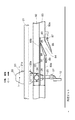
図1は、第1実施形態に係る堆積物の掻寄装置を示す正面模式図、図2は、第1実施形態に係る堆積物の掻寄装置を示す側面模式図である。
【0027】
本実施形態の堆積物の掻寄装置1は、図1に示すように、槽10の底面10bに堆積する汚泥等の堆積物を汚泥ピット10aに向けて掻き寄せるものであって、堆積物を掻き寄るフライト(掻寄羽根)12が水平方向に複数配設された梯子状の掻寄架台20と、この掻寄架台20を槽10の底面10bに対して略平行に往復運動させる駆動装置(駆動手段)50と、を備えている。
【0028】
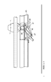
掻寄架台20は、図1及び図2に示すように、この掻寄架台20の往復方向に延在する2本の平行な駆動方向材21と、この2本の駆動方向材21に対して垂直に交差して配置されると共に互いに所定間隔離間された複数の平行材22と、を備えている。平行材22と駆動方向材21とは、図3に示すように、平行材22に固定された結合板22aと、駆動方向材21に固定された結合板21aと、がネジ固定されることによって接続され、梯子型の形状をなしている。
【0029】
この平行材22の両端には、この平行材22の軸周りに回転可能な主ローラ24が各々設置されている。また、この平行材22は、この平行材22の軸回りに揺動可能とされたアーム(掻寄羽根支持手段)25を、この平行材22の軸方向に離間して2つ備えている。そして、上述の結合板22aは、図3及び図4に示すように、アーム25が、平行材22の鉛直下方に垂下する第一の揺動位置から復動側(図4の図示右側)への揺動を制限する突起としてのアームストッパ(掻寄羽根揺動制限部材)26を備えている。
【0030】
各アーム25の先端部には、図1及び図2に示すように、平行材22の軸方向に延在し、この槽10の底面10bに堆積した堆積物を掻き寄せるフライト(掻寄羽根)12が設置されている。
【0031】
また、このアーム25は、図3に示すように、その先端側に平行材22の軸方向外側に向かって平行材22の両端の主ローラ24と略同じ位置まで突出するバー23と、バー23の先端に設置されこのバー23の軸周りに回転可能な副ローラ(被案内部)27と、を各々備えている。なお、副ローラ27はバー等を介してフライト12に設けられていてもよい。
【0032】
駆動装置50は、図1に示すように、正逆方向に回転可能なモータ51と、このモータ51による駆動力を伝達するチェーン52と、チェーン52により伝達された駆動力を水平方向の往復運動に変換すると共に変換された駆動力を固定板55を介して駆動方向材21に伝達するチェーン53と、チェーン53のたるみ等を調節するタイトナ54と、を備えており、掻寄架台20を図示左右方向に往復運動させる。
【0033】
また、駆動装置50は、図2及び図3に示すように、槽10における掻寄架台20の往復運動方向に平行な一対の側壁10c上に、矩形断面の樋状の主ガイドレール82を備えている。この主ガイドレール82は、槽10の底面10bに平行に、かつ、樋の開口側が掻寄架台20側を向くように設置されると共に、掻寄架台20の平行材22の両端の主ローラ24をこの主ガイドレール82内に常時収容している。この主ガイドレール82の底面10bからの高さは、図3及び図4に示すように、掻寄架台20のアーム25が第一の揺動位置にあるときに、フライト12の下端がほぼ槽10の底面10bに達するような高さとされている。そして、主ガイドレール82は、チェーン53等によって駆動される掻寄架台20を槽10の底面10bと平行に往復運動すべく案内する。
【0034】
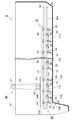
ここで、本実施形態の掻寄装置1は、掻寄架台20の運動方向に応じてフライト12の高さを調節するガイドユニット(案内手段)80を備えている。ガイドユニット80は、側壁10c上の主ガイドレール82の下方に、主ガイドレール82と同様に矩形断面の樋状の副ガイドレール(案内体)83を備えている。この副ガイドレール83の底面10bからの高さは、アーム25が第一の揺動位置とされたときの副ローラ27の位置よりも高くされ、掻寄架台20のアーム25の副ローラ27を溝内に収容し(図3の仮想線)、案内可能となっている。
【0035】
この副ガイドレール83の下面の下側フランジ83aには、図1及び図4に示すように、副ローラ27をこの副ガイドレール83内と副ガイドレール83の外(下方)との間で進退可能とする開口部84が形成されている。この開口部84は、掻寄架台20の平行材22の水平方向の設置間隔と同じ間隔でこの平行材22の数よりも1つ多く往復方向に複数形成されている。
【0036】
また、ガイドユニット80は、図4に示すように、副ガイドレール83の下側フランジ83aで、開口部84の復動方向側、すなわち、汚泥ピット10aから遠い側の縁の近傍には、開口部84の下方に向いて延在する板状の下側案内フラップ(第一揺動部材)85を備えている。この下側案内フラップ85は、開口部84に対応する大きさを有すると共に、上下方向に揺動自在に汚泥ピット10aから遠い側の縁の下側に軸90で軸支されている。
【0037】
さらに、このガイドユニット80は、この下側フランジ83aに、下側案内フラップ85が水平位置から所定の角度を超えて下方に揺動しないように制限するストッパ(第1揺動制限部材)86を備えると共に、下側案内フラップ85を下方に付勢する引張バネ(第一付勢手段)87を備えており、この下側案内フラップ85は、副ローラ27等による外力を受けない限り通常下方を向いて、ストッパ86によって揺動を止められた状態とされている。
【0038】
ここで、所定の角度としては、アーム25が平行材22の下方に垂下する第一の揺動位置とされている状態で掻寄架台20が復動(図示右方向に移動)する際に、副ローラ27が下側案内フラップ85の上面に当接可能であり、さらに、図5に示すように、アーム25が第一の揺動位置とされている状態で掻寄架台20が往動(図示左方向に移動)する際に、図6に示すように、アーム25の副ローラ27が下側案内フラップ85の下面に当接する角度に設定されている。
【0039】
そして、この下側案内フラップ85は、図4に示すように、所定の角度とされた状態で、第一の揺動位置とされたアーム25の副ローラ27が副ガイドレール83の下方を復動する場合に、図7に示すように、副ローラ27をその上面で受けて斜め上方向に誘導し開口部84を介して副ガイドレール83内に案内すると共に、逆に、副ガイドレール83上で案内される副ローラ27が開口部84の図示右側から往動する場合に、副ローラ27をその上面で受けて斜め下方に誘導し、開口部84を介して副ガイドレール83内から副ガイドレール83の外に案内する。
【0040】
さらに、図4に戻って、副ガイドレール83の下側フランジ83aで開口部84の往動側、すなわち、汚泥ピット10aに近い側の縁の近傍には、開口部84の上方に向かって延在する上側案内フラップ(第二揺動部材)88を備えている。
【0041】
この上側案内フラップ88は、開口部84を覆うことができる程度の大きさとされると共に、下側フランジ83aの往動側の縁の下側に、上下に揺動可能に軸91によって軸支されている。また、この上側案内フラップ88は、圧縮バネ(第二付勢手段)89により上側に付勢されており、上側案内フラップ88は、外力がかからない場合には通常上側に揺動して副ガイドレール83の上側フランジ(第二揺動制限部材)83bと接触し、それ以上上方へ揺動されないように制限されている。また、この上側案内フラップ88は、下方に揺動する場合には、開口部84を全て覆う水平状態となったところで、開口部84の縁の下側フランジ83aと接触し、これ以上下方への揺動が制限されている。
【0042】
そして、この上側案内フラップ88は、図8に示すように、アーム25の副ローラ27が開口部84の図示左側から副ガイドレール83内を案内される状態で汚泥ピット10a側から復動(図示右方向に移動)する際に、この副ローラ27と当接し、図9に示すように、この復動する副ローラ27に押されて下側に揺動されて開口部84を覆い、副ローラ27が開口部84の上を通過することを可能とし、図10に示すように、この副ローラ27を開口部84より復動側の副ガイドレール83へ到達させる。また逆に、アーム25の副ローラ27が副ガイドレール83内を案内される状態で、開口部84の図示右側から往動(図示左方向に移動)する際には、図7に示すように、副ローラ27が、開口部84を飛び越えて再び副ガイドレール83の往動方向側に入ることのないように、案内路を遮るふたの役目をすると共に、下面の傾斜によって確実に開口部84を介してこの副ローラ27を副ガイドレール83の下方に案内する。
【0043】
次に、このような堆積物の掻寄装置1の作用について説明する。
【0044】
まず、図4に示すように、掻寄架台20のアーム25が第一の揺動位置に位置すると共に、副ローラ27が副ガイドレール83の外(下)に位置し、掻寄架台20のフライト12が槽10の底に沈殿した堆積物を掻き寄せ可能な状態から説明する。
【0045】
まず、この状態から、モータ51を図1において時計方向に回転させ、チェーン52,53によって掻寄架台20を白矢印方向(図示左側)、すなわち、汚泥ピット10a方向に向かって動かす(往動)。これにより、各々のフライト12によって堆積物が汚泥ピット10a方向に掻き寄せられ、堆積物が汚泥ピット10a内に送られる(図4参照)。
【0046】
なお、フライト12が堆積物を掻き寄せる際、アーム25は、堆積物等から図示反時計回りのモーメントを受けるが、アームストッパ26によってアーム25のこれ以上の図示反時計方向への揺動が防止されているので、堆積物の掻き寄せが確実に可能とされている。
【0047】
このような掻き寄せを続けると、図5に示すように、アーム25等が往動方向側の隣の開口部84付近に到達する。このとき、アーム25の副ローラ27が下側案内フラップ85の下面と接触するが、下側案内フラップ85は、軸90を中心に上側に揺動可能とされているので、図6に示すように、上側に揺動し、このアーム25は障害なく開口部84下を通過して、堆積物を汚泥ピット10a方向へ掻き寄せ続ける。
【0048】
なお、副ローラ27が通過した後、下側案内フラップ85は、引張バネ87によって下側に付勢されているので、直ちに下方に揺動して元の所定の位置に確実に復帰する。
【0049】
このようにして、開口部84下を通過し、図4のような状態となった後、今度は、図1に示すモータ51を反時計方向に回転させ、掻寄架台20を黒矢印方向に移動させ、掻寄架台20を元の位置に復帰させる復動を始める。
【0050】
すると、アーム25等が再び開口部84に到達することとなるが、図7に示すように、今度はアーム25の副ローラ27が下側案内フラップ85の上面と接触し、この下側案内フラップ85は、ストッパ86によって、これ以上の下方への揺動が制限されているので、掻寄架台20が図示右方向に復動するに従って、副ローラ27はこの下側案内フラップ85の上面に案内されて上昇し、開口部84を介して副ガイドレール83内に向かって進入する。
【0051】
そして、さらに掻寄架台20が図示右方向に復動すると、図10に示すように、アーム25の副ローラ27は、副ガイドレール83内を走行し、このままの状態で図示右方向へ復動を続け、復動方向側の隣の開口部84に向かう移動を続ける。
【0052】
このとき、アーム25は、垂直下向の第一の揺動位置に対して、汚泥ピット10a側に図示時計回りに傾くこととなり、フライト12が槽10の底部から所定の距離離間されて上昇するので、これ以降の掻寄架台20の図示右方向への復動において、往動時に掻き寄せた堆積物と接触して堆積物を汚泥ピット10aと逆方向に戻してしまうことがない。また、このとき、フライト12が堆積物中からほぼ垂直上方に徐々に引き抜かれるので、堆積物のまきあげも抑制されている。
【0053】
このようにして、副ローラ27が副ガイドレール83内を走行し隣の開口部84の上側案内フラップ88に到達してさらに復動方向側へ走行することとなる(図8参照)。この時、副ローラ27が上側案内フラップ88の上面と接触し、図9に示すように、上側案内フラップ88は下方に揺動可能なため、副ローラ27により力を受けて下方に揺動されると共に、開口部84を覆ってこれよりも先の通路を形成し、副ローラ27は開口部84から下方に出ることなく開口部84上を通過する。副ローラ27が通過した後、上側案内フラップ88は、圧縮バネ89によって付勢されているので、再び上方に揺動して、図10のように、上側フランジ83bに接触して停止し、元の状態に復帰する。
【0054】
そして、開口部84を通過してしばらくした後、再びモータ51を図1に示す時計回りに回転させ、掻寄架台20の汚泥ピット10a方向への往動を始める。
【0055】
すると、副ガイドレール83内の副ローラ27が、開口部84に到達する。このとき、副ローラ27は、図7に示すように、下側案内フラップ85の上面によって形成される斜面に沿って開口部84を介して副ガイドレール83の外に徐々に案内されて、図4に示すように、アーム25が垂直下向の第一の揺動位置に復帰し、再び堆積物の掻き寄せが可能となる。
【0056】
このように副ローラ27が副ガイドレール83から外に出る一連の動作においては、上側案内フラップ88によって、復動時に開口部84が覆われて副ローラ27が一旦開口部84上を通過して開口部84より復動方向側(図示右側)に到達し、その後の往動時に副ローラ27が下側案内フラップ85の上面によって形成される斜面によって徐々に副ガイドレール83から外に出されるので、アーム25がスムーズに第一の揺動位置に復帰される。このため、フライト12が徐々にスムーズに堆積物内に進入するので、堆積物の巻き上げ等がより抑制されている。
【0057】
また、図7に示すように、副ガイドレール83内の副ローラ27が往動して開口部84に到達して下方に案内される際に、堆積物の沈殿量が多い等の理由により、アーム25が重力のみでは第一の揺動位置に戻りにくい場合でも、副ガイドレール83の開口部84よりも往動方向側への入口が上側案内フラップ88で閉じられていて副ローラ27の進入を防止すると共に、上側案内フラップ88の下面側によって副ローラ27が副ガイドレール83の下方に案内されるので、アーム25の副ローラ27は、開口部84を飛び越えて再び副ガイドレール83内に入ることなく、確実に副ガイドレール83から下方に案内される。これにより、掻寄架台20を汚泥ピット10a方向に往動する際に、アーム25がより確実に第一の揺動位置に復帰され、フライト12が底面から離間されたままとなることなく堆積物の掻き寄せが可能となっている。
【0058】
そして、このような往動と復動の一連の動作を繰り返すことにより、槽10の底面10bに沈殿する堆積物を、逆方向に戻すことや巻き上げることを防止し効率よく汚泥ピット10aに掻き寄せることが可能となっている。また、複数のフライト12を備え、各々のフライト12がこの一連の動作によって揺動されるので、堆積物が複数のフライト12によって分担して往動側に掻き寄せられ、一つのフライト12で掻き寄せを行う場合に比して掻寄架台20の往復運動の距離が短くなっている。
【0059】
なお、本実施形態の堆積物の掻寄装置1は、さらに、チェーンフライト式の掻寄装置と比較して、回転部や摺動部が少ないため、所用動力が少なくてすみ、また、チェーンやスプロケット、シューなどの摩耗部材が少なく、構造がシンプルであって低コスト化が可能であるという特徴を有している。また、この堆積物の掻寄装置1は、汚泥ピット等の洗浄が容易に行えると共に、上水道用の槽等においては薬品沈殿の効率を高める傾斜板の設置も容易とされ、さらに、設置に際して、パイプスキーマーなどの設置場所の制約を受けず、駆動部の位置が自由に設定でき、既存の槽の筐体に少ないはつり箇所で容易に設置できるという特徴を有している。
【0060】
次に、第2実施形態に係る堆積物の掻寄装置2について説明する。
【0061】
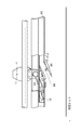
本実施形態の堆積物の掻寄装置2が第1実施形態の掻寄装置1と異なる第1の点は、駆動装置50が、図11及び図12に示すように、チェーン52等を介してモータ51からの回転駆動力が伝達され掻寄架台20の往復方向と垂直な水平軸回りに正逆回転されるスプロケット(歯車)103と、図11〜図13に示すように、駆動方向材21に固定部材102を介して曲折不能に固定され、掻寄架台20の往復方向に延在してスプロケット103と噛合するチェーン(噛合部材)101と、を備える点である。
【0062】
これによれば、スプロケット103の正逆転に応じて、このスプロケット103と噛合するチェーン101によって掻寄架台20が駆動方向材21の延在方向に好適に往復駆動され、上記実施形態と同様に堆積物の掻き寄せがなされる。特に、本実施形態では、第1実施形態におけるチェーン53が不要とされて、チェーンはずれ等の問題が低減されて掻寄装置2の信頼性を高めることができると共に、このチェーン53の遊びを調節するタイトナ54も不要とされ低コスト化が図られる。また、本実施形態のような駆動方式は、ピンギア方式とよばれ、掻寄架台20やチェーン101等の据え付け等の精度があまり要求されず設置やメンテナンスが容易とされ、堆積物等の夾雑物を含む水中での駆動にも適している。なお、場合によっては、スプロケット103に代えてピニオンギアを採用し、チェーン101に代えてラックを採用した、いわゆるラックピニオン方式としてもよい。
【0063】
また、本実施形態の堆積物の掻寄装置2が第1実施形態の掻寄装置1と異なる第2の点は、隣接する3つのアーム25同士がこれらのアーム25の揺動動作を連動すべく連結部材110によって連結されると共に、これら互いに連結されたアーム25の内の一つのアーム25にのみ副ローラ27が設けられた点であり、これに対応して、ガイドユニット80の下側案内フラップ85や上側案内フラップ88等で、残された副ローラ27の案内に寄与しないものは除去されている。ここで、便宜上、副ローラ27を有するアーム25と、副ローラ27を有するアーム25に支持されるフライト12との組合せを主動部100と呼び、副ローラ27を有さないアーム25と副ローラ27を有さないアーム25に支持されたフライト12との組合せを従動部105と呼ぶ。
【0064】
連結部材110は、駆動方向材21の軸方向に延在し、主動部100のアーム25と従動部105の2つのアーム25とに対してピン111で各々回動可能に連結されている。なお、連結部材110はアーム25に代えてフライト12に連結されていてもよい。また、互いに連結される従動部105の数や主動部100の数も1以上であれば限定されない。
【0065】
これによれば、従動部105のフライト12の揺動動作が主動部100のフライト12の揺動動作と連動するので、従動部105のフライト12によっても堆積物の掻寄がなされる。ここで、ガイドユニット80は、主動部100の副ローラ27のみを案内すればよく、第1実施形態の掻寄装置1に比して、従動部105の副ローラに対応するガイドユニット80の下側案内フラップ85や上側案内フラップ88等の数を減らすことができ、ガイドユニット80の低コスト化や簡素化ができる。
【0066】
なお、本発明に係る堆積物の掻寄装置は、上記実施形態に限定されるものではなく、種々の変形態様をとることが可能である。
【0067】
例えば、上記実施形態では、往動時にアーム25を第一の揺動位置に確実に復帰すると共に、この復帰の際にフライト12を徐々にスムーズに堆積物内に進入させるべく上側案内フラップ88を備えているが、堆積汚泥の量が少ない場合等には、これを備えなくてもよい。この場合でも、アーム25は重力によって第一の揺動位置に戻ろうとするので、往動時に開口部84に達した副ローラ27は下側案内フラップ85上に導かれて副ガイドレール83の外に案内される。
【0068】
また、上記実施形態では、下側案内フラップ85を下側に付勢する引張バネ87を備えているが、単に下側案内フラップ85の自重によってこの下側案内フラップ85を下側に付勢しても構わない。
【0069】
同様に、上側案内フラップ88は圧縮バネ89を備えているが、単に圧縮バネ89の位置に備えたカウンタウェイトの自重により上側案内フラップ88を上側に付勢しても構わない。
【0070】
また、上記実施形態の掻寄装置1は、案内手段として、副ガイドレール83、下側案内フラップ85及びストッパ86を備えているがこれに限られず、掻寄架台20の往復方向に延在し、往動時にフライト12を第一の揺動位置として移動可能とし、復動時にフライト12を第一の揺動位置より上方に揺動させた位置で副ローラ27等の被案内部を移動可能に案内するものであればよい。
【0071】
また、上記実施形態の掻寄装置1は、槽10に沈殿する汚泥を掻き寄せているが、槽の底部に堆積する堆積物であればこれに限られず、例えば粉体等でもよい。
【0072】
【発明の効果】
本発明の堆積物の掻寄装置によれば、掻寄架台の往動時に、案内手段が掻寄羽根を第一の揺動位置で垂下した状態で往動方向に移動可能とするので、往動と共に堆積物が掻寄羽根によって掻き寄せられる。
【0073】
一方、掻寄架台の復動時には、案内手段が、掻寄羽根が上方に揺動された状態となるように被案内部を案内して復動方向に移動可能とするので、復動時に掻寄羽根が槽の底部から離間される。このため、復動時における、掻寄羽根と往動時に掻き寄せた堆積物との接触が確実に防止される。
【0074】
これにより、堆積物の戻りや、巻き上げ等を起こすことなく効率的に堆積物を掻き寄せることが可能な堆積物の掻寄装置が提供される。
【図面の簡単な説明】
【図1】第1実施形態の掻寄装置の正面模式図である。
【図2】図1の掻寄装置の側面模式図である。
【図3】図2中のA部の拡大図である。
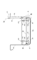
【図4】図1中の開口部近傍であって、副ローラが副ガイドレールより下方に位置する状態を示す模式図である。
【図5】図4の状態から、副ローラが往動方向に進んで隣の開口部近傍に達した状態を示す模式図である。
【図6】図5の状態から、副ローラが往動方向に進んで開口部の下方に達した状態を示す模式図である。
【図7】副ローラが下側案内フラップの上面に達した状態を示す模式図である。
【図8】副ローラが副ガイドレール内に位置する状態を示す模式図である。
【図9】図8の状態から、副ローラが復動方向に進んで上側案内フラップ上を通過する状態を示す模式図である。
【図10】図9の状態から、副ローラが復動方向に進んだ状態を示す模式図である。
【図11】第2実施形態の掻寄装置の正面模式図である。
【図12】図11の掻寄装置の側面模式図である。
【図13】図12中のB部の拡大図である。
【符号の説明】
1…堆積物の掻寄装置、10…槽、12…フライト(掻寄羽根)、20…掻寄架台、25…アーム(掻寄羽根支持手段)、26…アームストッパ(掻寄羽根揺動制限部材)、27…副ローラ(被案内部)、50…駆動装置(駆動手段)、80…ガイドユニット(案内手段)、83…副ガイドレール(案内体)、83b…上側フランジ(第二揺動制限部材)84…開口部、85…下側案内フラップ(第一揺動部材)、86…ストッパ(第一揺動制限部材)、87…引張バネ(第一付勢手段)、88…上側案内フラップ(第二揺動部材)、89…圧縮バネ(第二付勢手段)、101…チェーン(噛合部材)、103…スプロケット(歯車)、110…連結部材。[0001]
BACKGROUND OF THE INVENTION
The present invention relates to a deposit scraping device that scrapes deposits deposited on the bottom of a tank.
[0002]
[Prior art]
Conventionally, as a scraping device for deposits deposited on the bottom of a tank such as a sedimentation basin, a ladder-like scraping stand in which a plurality of flights (scraping blades) for scraping the deposits are arranged horizontally is arranged at the bottom of the tank. There is known a so-called reciprocating type scraping device that reciprocates with a cylinder.
[0003]
In such a reciprocating type scraping device, when the scraping base is moved forward and the deposit is scraped to one side by flight, the scraping base is moved back and returned to the original position again. Therefore, it is necessary to prevent the flight from returning to the original position after the deposits scraped during the forward movement.
[0004]
Therefore, in the conventional reciprocating type scraping device, the flight is wedge-shaped, and the deposit is scraped to one side at the vertical surface of this flight when the scraping base moves forward, while at the time of backward movement than during the forward movement A wedge-type reciprocating type scraping device that drives the scraping platform in the reverse direction at a high speed to prevent the deposits from returning by allowing the accumulated deposits to get over the slope of the flight. Raise the forward direction side of the gantry from the outside of the tank and tilt the cradle to a downward slope from the forward direction side toward the backward direction side. There is known an inclined reciprocating type scraper that keeps the deposits collected during the flight from returning.
[0005]
[Problems to be solved by the invention]
However, in the wedge-type reciprocating type scraping device, the deposit often does not get over the slope of the flight when the scraping table is moved back, and the deposit often returns or rolls up. Even in the type scraping device, in particular, the flight on the backward movement side of the scraping table often returns or winds up the deposit, and the deposit cannot be scraped efficiently.
[0006]
The present invention has been made in view of the above problems, and provides a deposit scraping device capable of scraping deposits efficiently without causing return of the deposits or winding up. Objective.
[0007]
[Means for Solving the Problems]
The deposit scraping device of the present invention is a deposit scraping device that moves the scraping blade along the bottom of the tank to scrape the deposit deposited on the bottom of the tank, and scrapes the scraping blade. A scraping blade support means that swings around a horizontal axis orthogonal to the moving direction of the vane, a scraping base on which the raking blade support means is installed, and a reciprocating parallel to the bottom of the tank A driving means for moving, a guided blade provided on the scraping blade or the scraping blade supporting means for supporting the scraping blade, and a reciprocating direction of the scraping stand, and the scraping blade is attached to the horizontal axis. It is possible to move in the forward direction as the first swing position that hangs downward, and guide the guided part so that it can be moved in the backward direction at the position where the scraping blade is swung upward from the first swing position. And guiding means forThere are a plurality of combinations of the scraping blade and the scraping blade support means for supporting the scraping blade, and the plurality of the scraping blade support means are arranged in parallel in the reciprocating direction with respect to the scraping stand.It is characterized by that.
[0008]
According to the deposit scraping device of the present invention, when the scraping base moves forward, the guide means can move in the forward movement direction with the scraping blade hanging down at the first swing position. Sediment is scraped by the scraping blades as it moves.
[0009]
On the other hand, when the scraping table is moved backward, the guided portion is guided by the guide means so that the scraping blade is swung upward and can be moved in the backward movement direction. The vane is spaced from the bottom of the tank. For this reason, the contact with the scraping blade | wing at the time of a backward movement and the deposit squeezed at the time of a forward movement is prevented reliably.In addition, each scraping blade is swung, and the deposit at the bottom of the tank is shared by the plurality of scraping blades and scraped to the forward movement side, so that the distance of the reciprocating motion of the scraping base can be shortened.
[0010]
Here, it is preferable to include a scraping blade swing restriction member that is installed on the scraping stand and restricts the scraping blade from swinging in the backward movement direction from the first swing position.
[0011]
At the time of forward movement, even if the scraping blade receives a force in the backward movement direction due to deposits or the like, it does not rock in the backward movement direction from the first rocking position, so the deposit is reliably scraped. .
[0012]
In addition, the guide means is a guide for guiding the guided portion movably moved in the reciprocating direction while the opening portion through which the guided portion can advance and retreat is formed on the lower surface at a predetermined distance in the reciprocating direction. A body, a first swinging member that extends downward from the edge of the opening in the backward direction of the opening and is pivotally supported so as to be swingable in the vertical direction, and a first swinging member. When the scraping blade located at the moving position moves forward, the lower surface of the first swinging member comes into contact with the guided portion, and when the scraping blade located at the first swinging position moves backward, the guided portion Is in contact with the upper surface of the first rocking member, and the first rocking member is positioned below the first rocking member so that the guided portion can be guided to the guide body through the opening. It is preferable to include a first swing limiting member that limits swinging to the side.
[0013]
Thereby, when the guided portion of the scraping blade that has been set to the first swing position moves forward and reaches below the opening, the guided portion of the scraping blade contacts the first swing member, Since the first swinging member swings upward and escapes, the movement of the scraping blade is not hindered, and the scraping blade reaches ahead of the opening, and the deposit is further scraped to a predetermined position.
[0014]
On the other hand, when the guided portion of the scraping blade that is in the first swing position reaches the lower side of the previous opening during the backward movement of the scraping base, the first swing member is covered by the scraping blade. The guide portion is received on the first swing member, and the first swing member is restricted from swinging downward by the first swing limit member. Since it guides to a guide body through an opening part, a scraping blade is rock | fluctuated upwards centering on a horizontal axis, and a scraping blade is spaced apart from the bottom part of a tank. Furthermore, when the guided portion passes under the guide body through the adjacent opening, the scraping blades hang down again to the first swing position, and the deposits are moved by moving the scraping stand forward. It is raked again by the scraping blade.
[0015]
That is, the deposit scraping device of the present invention is suitably realized by providing such guide means.
[0016]
Here, it is preferable to include first biasing means for biasing the first swing member downward.
[0017]
As a result, the first swing member is reliably maintained in the predetermined posture limited by the first swing limit member unless an external force or the like is applied, so that the guided portion of the scraping blade is guided during the backward movement. Guidance to the body is performed more reliably.
[0018]
Further, the guide body extends from the edge of the opening in the forward movement direction to the upper side of the opening and is pivotally supported so as to be swingable in the vertical direction, and the opening can be covered from above. When the scraping blade moves backward with the two swinging members, the second biasing means for biasing the second swinging member upward, and the guided portion of the scraping blade guided by the guide body When the upper surface of the second oscillating member is in contact with the guided portion of the scraping blade and the guided portion of the scraping blade is guided by the guide body, The guided portion abuts the lower surface of the second oscillating member, and the guided portion can be guided to the lower side of the guiding body through the opening, and the second oscillating member swings further upward. It is preferable to include a second rocking restriction member for restricting the movement.
[0019]
Accordingly, when the guided portion of the scraping blade moves back in the state where the guided portion of the scraping blade is guided by the guide body, if the guided portion of the scraping blade reaches above the opening of the guiding body, the guided body The portion abuts on the second swing member, and the second swing member swings downward to cover the opening and a guide path is formed on the opening, so that the guided portion goes downward from the opening. Without passing through this opening, it reaches the backward direction side. Then, after passing through the guided portion, the second rocking member returns to a predetermined rocking position restricted by the second rocking restriction member by being biased by the second biasing means. Further, when the guided portion of the scraping blade moves forward with the guided portion of the scraping blade guided by the guide body and the guided portion of the scraping blade guided by the guiding body reaches the opening, the guided portion is It is guided gradually downward through the opening along the upper surface of the first swing member, and the scraping blade is smoothly returned to the first swing position.
[0020]
In addition, at this time, the second swinging member whose upward swinging is restricted by the second swinging restricting member closes the entrance to the guide body on the forward direction side from the opening, and the second swinging member Since the guided portion can be guided below the guide body through the opening along the lower surface of the member, the guided portion is again guided to the guide body on the forward movement side from the opening. It can be taken out from the opening without any problem, and the scraping blade can be reliably returned to the first swing position.
[0021]
Moreover, it is preferable that the guided part is provided for each combination.
[0022]
Further, the guided portion may be provided for at least one of the combinations, and may include connecting means for interlocking the swinging motions of the scraping blades.
[0023]
According to this, the scraping blade according to the combination in which the guided portion is provided is swung by the guide means, and the scraping blade in the combination in which the guided portion is not provided in conjunction with this is also connected. Is swung by. In addition, since the number of guided portions can be reduced as compared with the number of combinations, the configuration of the guide means is not complicated, and the cost can be kept low.
[0024]
The driving means includes a gear that is rotated forward and backward about an axis perpendicular to the reciprocating direction of the scraping table, a gear that extends in the reciprocating direction of the scratching table and is fixed to the scratching table so as not to be bent. It is preferable to include a meshing member capable of meshing. According to this, the scraper can be reciprocated easily and suitably.
[0025]
DETAILED DESCRIPTION OF THE INVENTION
DESCRIPTION OF EXEMPLARY EMBODIMENTS Hereinafter, preferred embodiments of a deposit scraping apparatus according to the invention will be described in detail with reference to the accompanying drawings. In the description of the drawings, the same or corresponding elements are denoted by the same reference numerals, and redundant description is omitted.
[0026]
FIG. 1 is a schematic front view showing a deposit scratching apparatus according to the first embodiment, and FIG. 2 is a schematic side view showing the deposit scratching apparatus according to the first embodiment.
[0027]
As shown in FIG. 1, the
[0028]
As shown in FIG. 1 and FIG. 2, the
[0029]
At both ends of the
[0030]
As shown in FIGS. 1 and 2, a flight (scraping blade) that extends in the axial direction of the
[0031]
Further, as shown in FIG. 3, the
[0032]
As shown in FIG. 1, the driving
[0033]
Further, as shown in FIGS. 2 and 3, the driving
[0034]
Here, the
[0035]
As shown in FIGS. 1 and 4, the sub-roller 27 is advanced and retracted between the
[0036]
Further, as shown in FIG. 4, the
[0037]
Further, the
[0038]
Here, as the predetermined angle, when the
[0039]
As shown in FIG. 4, the
[0040]
Further, referring back to FIG. 4, the
[0041]
The
[0042]
As shown in FIG. 8, the
[0043]
Next, the operation of the
[0044]
First, as shown in FIG. 4, the
[0045]
First, from this state, the
[0046]
When the
[0047]
If such scraping is continued, as shown in FIG. 5, the
[0048]
Since the
[0049]
In this way, after passing under the
[0050]
Then, the
[0051]
Then, when the
[0052]
At this time, the
[0053]
In this way, the
[0054]
Then, after passing through the
[0055]
Then, the
[0056]
Thus, in a series of operations in which the sub-roller 27 goes out of the
[0057]
Further, as shown in FIG. 7, when the
[0058]
Then, by repeating such a series of forward and backward movements, the sediment deposited on the
[0059]
In addition, the
[0060]
Next, the
[0061]
The first point that the
[0062]
According to this, according to the forward / reverse rotation of the
[0063]
Further, the second point that the
[0064]
The connecting
[0065]
According to this, since the swinging motion of the
[0066]
In addition, the scraping apparatus according to the present invention is not limited to the above-described embodiment, and can be variously modified.
[0067]
For example, in the above embodiment, the
[0068]
In the above embodiment, the
[0069]
Similarly, although the
[0070]
Moreover, although the
[0071]
Moreover, although the
[0072]
【The invention's effect】
According to the deposit scraping device of the present invention, when the scraping base moves forward, the guide means can move in the forward movement direction with the scraping blade hanging down at the first swing position. Sediment is scraped by the scraping blades as it moves.
[0073]
On the other hand, when the scraping base is moved backward, the guide means guides the guided portion so that the scraping blade is swung upward and can move in the backward moving direction. The vane is spaced from the bottom of the tank. For this reason, the contact with the scraping blade | wing at the time of a backward movement and the deposit squeezed at the time of a forward movement is prevented reliably.
[0074]
Thus, a deposit scraping device is provided that can scrape the deposit efficiently without causing return of the deposit or winding up.
[Brief description of the drawings]
FIG. 1 is a schematic front view of a scraping device according to a first embodiment.
FIG. 2 is a schematic side view of the scraping device of FIG. 1;
FIG. 3 is an enlarged view of a portion A in FIG.
4 is a schematic view showing a state in which the sub roller is positioned below the sub guide rail in the vicinity of the opening in FIG. 1. FIG.
5 is a schematic view showing a state in which the sub roller has advanced in the forward movement direction and has reached the vicinity of the adjacent opening from the state of FIG. 4;
6 is a schematic diagram showing a state in which the sub roller has advanced in the forward movement direction and has reached the lower part of the opening from the state of FIG. 5;
FIG. 7 is a schematic view showing a state in which the auxiliary roller has reached the upper surface of the lower guide flap.
FIG. 8 is a schematic view showing a state in which a sub roller is positioned in a sub guide rail.
9 is a schematic diagram showing a state in which the sub roller advances in the backward movement direction and passes over the upper guide flap from the state of FIG. 8. FIG.
10 is a schematic diagram showing a state in which the sub roller has advanced in the backward movement direction from the state of FIG.
FIG. 11 is a schematic front view of the scraping device according to the second embodiment.
12 is a schematic side view of the scraping device of FIG. 11. FIG.
13 is an enlarged view of a portion B in FIG.
[Explanation of symbols]
DESCRIPTION OF
Claims (8)
前記掻寄羽根を前記掻寄羽根の前記移動方向と直交する水平軸周りに揺動自在に支持する掻寄羽根支持手段と、
前記掻寄羽根支持手段が設置される掻寄架台と、
前記掻寄架台を前記槽の底に平行に往復運動させる駆動手段と、
前記掻寄羽根又は掻寄羽根支持手段に設けられた被案内部と、
前記掻寄架台の往復方向に延在し、前記掻寄羽根を前記水平軸の下方に垂下する第一の揺動位置として往動方向に移動可能とし、前記掻寄羽根を前記第一の揺動位置より上方に揺動させた位置で前記被案内部を復動方向に移動可能に案内する案内手段とを備え、
前記掻寄羽根と前記掻寄羽根を支持する前記掻寄羽根支持手段との組合せを複数有し、前記掻寄羽根支持手段は前記掻寄架台に対して前記往復方向に複数並設されることを特徴とする、堆積物の掻寄装置。A scraping device for deposits that moves the scraping blade along the bottom of the tank and scrapes the deposits deposited on the bottom of the tank,
Scraping blade support means for swingably supporting the scraping blade around a horizontal axis perpendicular to the moving direction of the scraping blade;
A scraping stand on which the scraping blade support means is installed;
Drive means for reciprocating the scraper in parallel with the bottom of the tank;
A guided portion provided on the scraping blade or the scraping blade support means;
The scraping blade extends in the reciprocating direction of the scraping base, and the scraping blade is movable in the forward movement direction as a first swinging position that hangs down below the horizontal axis, and the scraping blade is moved in the first swinging position. A guide means for guiding the guided portion so as to be movable in the backward movement direction at a position swung upward from the moving position ;
The raking blade and has a plurality of combination of the raking blade supporting means for supporting said raking blades, the raking blade support means is a plurality juxtaposed in the reciprocating direction with respect to the raking frame Rukoto A scraping device for deposits.
前記案内体で前記開口部の前記復動方向側の縁から当該開口部の下方に向けて延在し、上下方向に揺動自在に軸支された第一揺動部材と、
前記第一の揺動位置に位置する掻寄羽根が往動する際に前記第一揺動部材の下面が前記被案内部と当接すると共に前記第一の揺動位置に位置する掻寄羽根が復動する際に前記被案内部が当該第一揺動部材の上面に当接し前記開口部を介して当該被案内部を前記案内体に案内可能とする姿勢を、前記第一揺動部材にとらせ当該第一揺動部材のそれ以上下側への揺動を制限する第一揺動制限部材と、
を備えることを特徴とする、請求項1又は2に記載の堆積物の掻寄装置。The guide means is formed such that an opening portion through which the guided portion can advance and retreat is formed on the lower surface at a predetermined distance in the reciprocating direction, and the guided portion entering through the opening portion is movable in the reciprocating direction. A guide to guide to,
A first oscillating member that extends downward from the edge of the opening in the guide body toward the lower side of the opening and is pivotally supported so as to be swingable in the vertical direction;
When the scraping blade located at the first swing position moves forward, the lower surface of the first swing member abuts on the guided portion and the scraping blade positioned at the first swing position In the backward movement, the guided portion is in contact with the upper surface of the first swing member, and the guide member is guided to the guide body through the opening. A first swing restricting member for restricting further downward swing of the first swing member;
The scraping apparatus for deposits according to claim 1 or 2, characterized by comprising:
前記第二揺動部材を上方側に付勢する第二付勢手段と、
前記被案内部が前記案内体に案内された状態で前記掻寄羽根が復動する際に前記第二揺動部材の上面が当該被案内部と当接すると共に前記被案内部が前記案内体に案内された状態で前記掻寄羽根が往動する際に当該被案内部が当該第二揺動部材の下面に当接し前記開口部を介して当該被案内部を前記案内体の下方に案内可能な姿勢で、当該第二揺動部材のそれ以上上側への揺動を制限する第二揺動制限部材と、
を備えることを特徴とする、請求項3又は4に記載の堆積物の掻寄装置。The guide body extends from the edge of the opening in the forward movement direction to the upper side of the opening and is pivotally supported so as to be swingable in the vertical direction, and can cover the opening from above. A second rocking member;
Second urging means for urging the second swinging member upward;
When the scraping blade moves backward in a state where the guided portion is guided by the guide body, the upper surface of the second swinging member comes into contact with the guided portion, and the guided portion is brought into contact with the guide body. When the scraping blade moves forward in a guided state, the guided portion comes into contact with the lower surface of the second swinging member, and the guided portion can be guided below the guide body through the opening. A second swing limiting member that limits the upward swing of the second swing member,
The scraping device for deposits according to claim 3 or 4, characterized by comprising:
Priority Applications (1)
| Application Number | Priority Date | Filing Date | Title |
|---|---|---|---|
| JP2002192451A JP3746023B2 (en) | 2001-10-12 | 2002-07-01 | Sediment scraping device |
Applications Claiming Priority (3)
| Application Number | Priority Date | Filing Date | Title |
|---|---|---|---|
| JP2001315434 | 2001-10-12 | ||
| JP2001-315434 | 2001-10-12 | ||
| JP2002192451A JP3746023B2 (en) | 2001-10-12 | 2002-07-01 | Sediment scraping device |
Related Child Applications (1)
| Application Number | Title | Priority Date | Filing Date |
|---|---|---|---|
| JP2004180031A Division JP4069098B2 (en) | 2001-10-12 | 2004-06-17 | Sediment scraping device |
Publications (3)
| Publication Number | Publication Date |
|---|---|
| JP2003181209A JP2003181209A (en) | 2003-07-02 |
| JP2003181209A5 JP2003181209A5 (en) | 2005-04-28 |
| JP3746023B2 true JP3746023B2 (en) | 2006-02-15 |
Family
ID=27615378
Family Applications (1)
| Application Number | Title | Priority Date | Filing Date |
|---|---|---|---|
| JP2002192451A Expired - Fee Related JP3746023B2 (en) | 2001-10-12 | 2002-07-01 | Sediment scraping device |
Country Status (1)
| Country | Link |
|---|---|
| JP (1) | JP3746023B2 (en) |
Families Citing this family (4)
| Publication number | Priority date | Publication date | Assignee | Title |
|---|---|---|---|---|
| MY131064A (en) * | 2001-04-21 | 2007-07-31 | Fujiwara Michihiro | Scraping device for sludge or the like |
| JP4536595B2 (en) * | 2005-05-26 | 2010-09-01 | 荏原エンジニアリングサービス株式会社 | Sludge scraping machine |
| JP4629004B2 (en) * | 2006-07-18 | 2011-02-09 | 住友重機械エンバイロメント株式会社 | Scraping device |
| JP4633705B2 (en) * | 2006-11-01 | 2011-02-16 | 住友重機械エンバイロメント株式会社 | Sludge scraping device |
Family Cites Families (6)
| Publication number | Priority date | Publication date | Assignee | Title |
|---|---|---|---|---|
| JPS5358151A (en) * | 1976-11-05 | 1978-05-25 | Maezawa Kogyo | Apparatus for scraping sludge |
| JPS5369064U (en) * | 1976-11-11 | 1978-06-09 | ||
| JPS57194011A (en) * | 1981-05-25 | 1982-11-29 | Hitachi Plant Eng & Constr Co Ltd | Scraping machine for settled matter |
| JPS58186806U (en) * | 1982-06-07 | 1983-12-12 | 神鋼フアウドラ−株式会社 | Underwater towed sludge scraping device |
| JPH0422801Y2 (en) * | 1987-05-30 | 1992-05-26 | ||
| JP2000051614A (en) * | 1998-08-05 | 2000-02-22 | Mitsuhiro Fujiwara | Deposite scraper for sand basin or the like |
-
2002
- 2002-07-01 JP JP2002192451A patent/JP3746023B2/en not_active Expired - Fee Related
Also Published As
| Publication number | Publication date |
|---|---|
| JP2003181209A (en) | 2003-07-02 |
Similar Documents
| Publication | Publication Date | Title |
|---|---|---|
| JP3746023B2 (en) | Sediment scraping device | |
| JP4522979B2 (en) | Scraping device for sediment and levitated matter | |
| JP4069098B2 (en) | Sediment scraping device | |
| EP0607447B1 (en) | Sludge scraping apparatus | |
| JP3315682B2 (en) | Sludge scraper | |
| JP6917326B2 (en) | Rear descent Front suction type dust remover | |
| US4138334A (en) | Trash collector | |
| JP3908989B2 (en) | Floating object scraping device | |
| JP3909005B2 (en) | Sediment scraping device | |
| JP6473480B2 (en) | Weight automatic tensioning device and sludge scraper | |
| JP2021031852A (en) | Screen rotary dust remover | |
| JP4196311B2 (en) | Sludge scraping device | |
| JP4317426B2 (en) | Scraping device for sediment and levitated matter | |
| JP3033482U (en) | Sludge scraper | |
| JP6058509B2 (en) | Sludge scraping machine | |
| JP3735746B2 (en) | Suspended scraping device | |
| JP4099162B2 (en) | Method of detecting malfunction of deposit scraping device and malfunction detection device of deposit scraping device | |
| JP2008080203A (en) | Scraping device for deposit and floated matter | |
| JP2007050321A (en) | Deposit scraping device | |
| JP4584887B2 (en) | Sludge scraping device | |
| JP2601286Y2 (en) | Sludge scraper | |
| JP2010253468A (en) | Apparatus for raking sludge | |
| CN114029298A (en) | Composite flushing type stable storage tank | |
| JPS5851220Y2 (en) | Screen automatic dust remover | |
| JP4509989B2 (en) | Scum pipe and method of operating scum pipe |
Legal Events
| Date | Code | Title | Description |
|---|---|---|---|
| A521 | Request for written amendment filed |
Free format text: JAPANESE INTERMEDIATE CODE: A523 Effective date: 20040617 |
|
| A977 | Report on retrieval |
Free format text: JAPANESE INTERMEDIATE CODE: A971007 Effective date: 20051018 |
|
| TRDD | Decision of grant or rejection written | ||
| A01 | Written decision to grant a patent or to grant a registration (utility model) |
Free format text: JAPANESE INTERMEDIATE CODE: A01 Effective date: 20051115 |
|
| A61 | First payment of annual fees (during grant procedure) |
Free format text: JAPANESE INTERMEDIATE CODE: A61 Effective date: 20051118 |
|
| R150 | Certificate of patent or registration of utility model |
Ref document number: 3746023 Country of ref document: JP Free format text: JAPANESE INTERMEDIATE CODE: R150 Free format text: JAPANESE INTERMEDIATE CODE: R150 |
|
| S111 | Request for change of ownership or part of ownership |
Free format text: JAPANESE INTERMEDIATE CODE: R313111 |
|
| FPAY | Renewal fee payment (event date is renewal date of database) |
Free format text: PAYMENT UNTIL: 20081202 Year of fee payment: 3 |
|
| R350 | Written notification of registration of transfer |
Free format text: JAPANESE INTERMEDIATE CODE: R350 |
|
| FPAY | Renewal fee payment (event date is renewal date of database) |
Free format text: PAYMENT UNTIL: 20091202 Year of fee payment: 4 |
|
| R250 | Receipt of annual fees |
Free format text: JAPANESE INTERMEDIATE CODE: R250 |
|
| FPAY | Renewal fee payment (event date is renewal date of database) |
Free format text: PAYMENT UNTIL: 20101202 Year of fee payment: 5 |
|
| R250 | Receipt of annual fees |
Free format text: JAPANESE INTERMEDIATE CODE: R250 |
|
| FPAY | Renewal fee payment (event date is renewal date of database) |
Free format text: PAYMENT UNTIL: 20111202 Year of fee payment: 6 |
|
| R250 | Receipt of annual fees |
Free format text: JAPANESE INTERMEDIATE CODE: R250 |
|
| S531 | Written request for registration of change of domicile |
Free format text: JAPANESE INTERMEDIATE CODE: R313531 |
|
| FPAY | Renewal fee payment (event date is renewal date of database) |
Free format text: PAYMENT UNTIL: 20111202 Year of fee payment: 6 |
|
| R350 | Written notification of registration of transfer |
Free format text: JAPANESE INTERMEDIATE CODE: R350 |
|
| FPAY | Renewal fee payment (event date is renewal date of database) |
Free format text: PAYMENT UNTIL: 20111202 Year of fee payment: 6 |
|
| FPAY | Renewal fee payment (event date is renewal date of database) |
Free format text: PAYMENT UNTIL: 20121202 Year of fee payment: 7 |
|
| R250 | Receipt of annual fees |
Free format text: JAPANESE INTERMEDIATE CODE: R250 |
|
| FPAY | Renewal fee payment (event date is renewal date of database) |
Free format text: PAYMENT UNTIL: 20121202 Year of fee payment: 7 |
|
| FPAY | Renewal fee payment (event date is renewal date of database) |
Free format text: PAYMENT UNTIL: 20131202 Year of fee payment: 8 |
|
| R250 | Receipt of annual fees |
Free format text: JAPANESE INTERMEDIATE CODE: R250 |
|
| R250 | Receipt of annual fees |
Free format text: JAPANESE INTERMEDIATE CODE: R250 |
|
| S802 | Written request for registration of partial abandonment of right |
Free format text: JAPANESE INTERMEDIATE CODE: R311802 |
|
| R350 | Written notification of registration of transfer |
Free format text: JAPANESE INTERMEDIATE CODE: R350 |
|
| S531 | Written request for registration of change of domicile |
Free format text: JAPANESE INTERMEDIATE CODE: R313531 |
|
| R350 | Written notification of registration of transfer |
Free format text: JAPANESE INTERMEDIATE CODE: R350 |
|
| LAPS | Cancellation because of no payment of annual fees |