JP3881339B2 - 位置測定装置 - Google Patents
位置測定装置 Download PDFInfo
- Publication number
- JP3881339B2 JP3881339B2 JP2003525220A JP2003525220A JP3881339B2 JP 3881339 B2 JP3881339 B2 JP 3881339B2 JP 2003525220 A JP2003525220 A JP 2003525220A JP 2003525220 A JP2003525220 A JP 2003525220A JP 3881339 B2 JP3881339 B2 JP 3881339B2
- Authority
- JP
- Japan
- Prior art keywords
- ref
- reference pulse
- signal
- incremental
- position measuring
- Prior art date
- Legal status (The legal status is an assumption and is not a legal conclusion. Google has not performed a legal analysis and makes no representation as to the accuracy of the status listed.)
- Expired - Fee Related
Links
- 238000005259 measurement Methods 0.000 claims abstract description 20
- 230000003287 optical effect Effects 0.000 claims abstract description 17
- 230000000737 periodic effect Effects 0.000 claims abstract description 13
- 230000003321 amplification Effects 0.000 claims description 13
- 238000003199 nucleic acid amplification method Methods 0.000 claims description 13
- 230000007704 transition Effects 0.000 claims description 12
- 230000004907 flux Effects 0.000 claims description 10
- 238000012545 processing Methods 0.000 claims description 9
- 230000000694 effects Effects 0.000 claims description 3
- 238000005286 illumination Methods 0.000 claims description 2
- 238000000034 method Methods 0.000 abstract description 4
- 230000008901 benefit Effects 0.000 description 5
- 230000009471 action Effects 0.000 description 4
- 230000004048 modification Effects 0.000 description 4
- 238000012986 modification Methods 0.000 description 4
- 238000001514 detection method Methods 0.000 description 3
- 238000010586 diagram Methods 0.000 description 3
- 108010014172 Factor V Proteins 0.000 description 2
- 230000002238 attenuated effect Effects 0.000 description 2
- 230000015572 biosynthetic process Effects 0.000 description 2
- 230000008878 coupling Effects 0.000 description 2
- 238000010168 coupling process Methods 0.000 description 2
- 238000005859 coupling reaction Methods 0.000 description 2
- 230000010354 integration Effects 0.000 description 2
- 230000008859 change Effects 0.000 description 1
- 230000000295 complement effect Effects 0.000 description 1
- 230000001010 compromised effect Effects 0.000 description 1
- 238000000354 decomposition reaction Methods 0.000 description 1
- 230000001419 dependent effect Effects 0.000 description 1
- 238000006073 displacement reaction Methods 0.000 description 1
- 230000005684 electric field Effects 0.000 description 1
- 238000011156 evaluation Methods 0.000 description 1
- 239000011521 glass Substances 0.000 description 1
- 231100001261 hazardous Toxicity 0.000 description 1
- 230000004044 response Effects 0.000 description 1
Images


Classifications
-
- G—PHYSICS
- G01—MEASURING; TESTING
- G01D—MEASURING NOT SPECIALLY ADAPTED FOR A SPECIFIC VARIABLE; ARRANGEMENTS FOR MEASURING TWO OR MORE VARIABLES NOT COVERED IN A SINGLE OTHER SUBCLASS; TARIFF METERING APPARATUS; MEASURING OR TESTING NOT OTHERWISE PROVIDED FOR
- G01D5/00—Mechanical means for transferring the output of a sensing member; Means for converting the output of a sensing member to another variable where the form or nature of the sensing member does not constrain the means for converting; Transducers not specially adapted for a specific variable
- G01D5/26—Mechanical means for transferring the output of a sensing member; Means for converting the output of a sensing member to another variable where the form or nature of the sensing member does not constrain the means for converting; Transducers not specially adapted for a specific variable characterised by optical transfer means, i.e. using infrared, visible, or ultraviolet light
- G01D5/32—Mechanical means for transferring the output of a sensing member; Means for converting the output of a sensing member to another variable where the form or nature of the sensing member does not constrain the means for converting; Transducers not specially adapted for a specific variable characterised by optical transfer means, i.e. using infrared, visible, or ultraviolet light with attenuation or whole or partial obturation of beams of light
- G01D5/34—Mechanical means for transferring the output of a sensing member; Means for converting the output of a sensing member to another variable where the form or nature of the sensing member does not constrain the means for converting; Transducers not specially adapted for a specific variable characterised by optical transfer means, i.e. using infrared, visible, or ultraviolet light with attenuation or whole or partial obturation of beams of light the beams of light being detected by photocells
- G01D5/36—Forming the light into pulses
- G01D5/366—Particular pulse shapes
Description
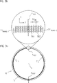
この例では、増分式目盛が、測定区間の第1の部分D1において更に第1の横断下部構造を備え、この横断下部構造は、この横断下部構造に入射する光束を、少なくとも1つの第1の空間方向に偏向させる。図2,3のa及びbにおいて図示された実施例の場合、第1の部分D1は、部分ディスクもしくは増分式目盛の左の180°の円形セグメントにわたって延在する。第1の部分D1に隣接する第2の部分D2においては、増分式目盛が、第2の横断下部構造を備え、この横断下部構造は、入射する光束を、少なくとも1つの第2の空間方向に偏向させる。第2の空間方向は、第1の空間方向とは異なっている。従って、図示された例では、増分式目盛の右の180°の円形セグメントが、測定区間の第2の部分D2である。従って、第1及び第2の部分D1とD2との間には、移行領域において、増分式目盛のそれぞれの横断下部構造の光学的な偏向作用に関する不連続が存在し、この不連続は、最終的に、この位置で参照パルス信号REFを発生させるためだけに利用される。
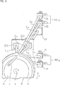
光源から来る光束Sがもっぱら増分式目盛の第1の部分D1を走査もしくは通過する間は、この部分における横断下部構造によって第1の空間方向RR1への偏向だけが行なわれ、即ち、第1の参照パルス検出器要素24に作用する光束ST1が結果として生じる。第1の参照パルス検出器要素24だけが、この測定段階で入射する光線強度を記録し、これにより、出力部に付与される第1の参照パルス部分信号REF1 を記録する。増分式目盛の第2の部分D2の走査を行なう場合は、全く逆の関係が存在し、即ち、第2の空間方向RR2における第2の参照パルス検出器要素25だけが、光束ST2の入射する光線強度を記録するか、もしくはその際、第2の参照パルス検出器要素の出力部に第2の参照パルス部分信号REF2が付与される。従って、両方の部分D1とD2の間の移行領域もしくは参照位置xREFでは、両方の参照パルス部分信号REF1 ,REF2 に関する特徴的な信号経過が存在し、この信号経過は、本発明により参照パルス信号REFを発生させるために利用することができる。
図3のbの例で図示された増分式目盛における適当な横断下部構造の形態以外に、更にまた本発明の枠内の選択的な変形例も使用可能である。
例えば、増分式目盛の部分領域が三角形の輪郭制限部をy方向に沿って備える周期的な横断下部構造も使用することができる。
更に、増分式目盛のそれぞれの部分領域には、シリンダ形レンズも測定方向xに対して横断方向に偏向させる下部構造として使用することができる。このようなシリンダレンズは、小さい検出器要素に対して横断方向に偏向された回折系列をフォーカスするためにも使用することができる。この場合、増分式信号を発生させるために利用される0位の回折系列は、フォーカスされないかもしくはデフォーカスされる。
即ち、
REFS3>REFS5の場合REFH1=1
もしくは
REFS3<REFS5の場合REFH1=0
及び
REFS6>REFS4の場合REFH2=1
もしくは
REFS6<REFS4の場合REFH2=0
である。
10 スケール
11 担持要素
12 トラック
22.1,22.2 走査目盛
23〜27 検出器要素
REF1 〜REF4 参照パルス部分信号
REFS1,REFS2 参照パルス和信号
RR1〜RR4 空間方向
S+1,S−1 部分光束
ST1〜ST4 光束
x 測定方向
Claims (17)
- −その内部に測定方向(x)に延在する一定の増分式目盛周期(TPINC)を有する周期的な増分式目盛が配設され、かつ少なくとも一定の参照位置(XREF)において参照パルス信号(REF)を発生させるための光学特性に関する不連続を備えるトラック(12)を有するスケール(10)と、
−スケール(10)に対して相対的に測定方向(x)に増分式目盛を有するトラック(12)の一定の測定区間(D)にわたって可動であり、光源(21)以外に、増分式目盛を光電走査するための複数の検出器要素(23,24,25,26,27)を有する走査ユニット(20)と、
から成る、周期的な増分式信号及び少なくとも1つの参照パルス信号を発生させるための位置測定装置において、
−トラック(12)内の測定区間(D)の第1の部分(D1)において、増分式目盛が、入射する光束(S)を少なくとも1つの第1の空間方向(RR1)へと偏向させる第1の横断下部構造を備えており、第1の部分(D 1 )に隣接するトラック(12)内の測定区間(D)の第2の部分(D2 )において、増分式目盛が、入射する光束(S)を第1の空間方向(RR1)とは異なる少なくとも1つの第2の空間方向(RR2)へと偏向させる第2の横断下部構造を備えており、従って、第1と第2の部分(D1 ,D2)の間の移行領域において、増分式目盛の横断下部構造の光学偏向作用に関する不連続が存在し、
−増分式目盛が、増分式目盛周期(TP INC )で測定方向(x)に周期的に配設された異なった光学特性を有する部分領域(TB1,TB2)から成り、その際、部分領域(TB1,TB2)が、長手方向の広がりを、測定方向(x)に対して垂直に整向されている方向(y)に備えており、横断下部構造が、それぞれ、部分領域(TB1,TB2)の長手方向の広がりの方向(y)に沿った周期的な輪郭制限部を有する構造体として一定の偏向目盛周期(TP TRANS,1 ,TP TRANS,2 )で形成されており、
−走査ユニット(20)の側に、それぞれ1つ又は複数の参照パルス検出器要素(24,25,26,27)が異なった空間方向(RR1,RR2)に配設されており、これらの参照パルス検出器要素に、参照パルス部分信号(REF1 〜REF4)が付与され、これら参照パルス部分信号の処理から、光学偏向作用に関する不連続が存在する第1と第2の部分(D 1 ,D 2 )の間の移行領域内の参照位置で、参照パルス信号(REF)が結果として生じることを特徴とする位置測定装置。 - 第1の横断下部構造が、第1の偏向目盛周期(TPTRANS,1)を備え、第2の横断下部構造が、第1の偏向目盛周期(TPTRANS,1)とは異なる第2の偏向目盛周期(TPTRANS,2)を備えることを特徴とする請求項1に記載の位置測定装置。
- −第1の横断下部構造が、第1の空間方向(RR1)及びこの第1の空間方向(RR1)とは異なる別の第4の空間方向(RR4)への偏向を行ない、
−第2の横断下部構造が、第2の空間方向(RR2)及びこの第2の空間方向(RR2)とは異なる別の第3の空間方向(RR3)への偏向を行なうことを特徴とする請求項1に記載の位置測定装置。 - 光束(ST1〜ST4)の偏向を結果として行なう空間方向(RR1〜RR4)が、測定方向(x)に対して垂直にまた増分式目盛の部分領域(TB1,TB2)の長手方向の広がりの方向(y)に対して平行に整向されている平面を固定することを特徴とする請求項3に記載の位置測定装置。
- 第1及び第4又は第2及び第3の空間方向(RR1−RR4)が、それぞれの偏向目盛周期(TPTRANS,1 ,TPTRANS,2)を有する横断下部構造によって+/−1位の回折系列への回折が結果として生じる方向に相当することを特徴とする請求項3に記載の位置測定装置。
- 増分式目盛の部分領域が、その長手方向の広がりの方向(y)にサイン波形の輪郭制限部を備えることを特徴とする請求項1に記載の位置測定装置。
- 増分式目盛の部分領域が、その長手方向の広がりの方向(y)に三角形の輪郭制限部を備えることを特徴とする請求項1に記載の位置測定装置。
- 増分式目盛が、ディスク状の担持要素(11)上に円形に周方向に配設されており、増分式目盛の第1及び第2の部分(D1 ,D2)が隣接する2つの円形セグメントであることを特徴とする請求項1に記載の位置測定装置。
- 両方の円形セグメントが、それぞれ180°にわたって延在し、従って、向かい合って位置する2つの参照位置(xREF)において周方向に沿って参照パルス信号(REF)が発生可能であることを特徴とする請求項8に記載の位置測定装置。
- 増分式目盛が、位相格子として形成されていることを特徴とする請求項1に記載の位置測定装置。
- 増分式目盛が、透過光目盛として形成されていることを特徴とする請求項1に記載の位置測定装置。
- 増分式目盛の照明が、視準された小さい直径を有する光束(S)によって行なわれることを特徴とする請求項1に記載の位置測定装置。
- −第1及び第4の空間方向(RR1,RR4)に、第1及び第4の参照パルス検出器要素(24,27)が配設されており、これらの参照パルス検出器要素が、付与される第1及び第4の参照パルス部分信号(REF1 ,REF4)から第1の参照パルス和信号(REFS1)が結果として生じるように接続されており、
−第2及び第3の空間方向(RR2,RR3)に、第2及び第3の参照パルス検出器要素(25,26)が配設されており、これらの参照パルス検出器要素が、付与される第2及び第3の参照パルス部分信号(REF2 ,REF3)から第2の参照パルス和信号(REFS2)が結果として生じるように接続されており、
−その際、第1及び第2の参照パルス和信号(REFS1,REFS2)の処理から参照パルス信号(REF)が結果として生じることを特徴とする請求項3に記載の位置測定装置。 - −第1の参照パルス和信号(REFS1)から、増幅及び減衰によって別の第3及び第4の参照パルス和信号(REFS3,REFS4)が結果として生じ、
−第2の参照パルス和信号(REFS2)から、減衰及び増幅によって別の第5及び第6の参照パルス和信号(REFS5,REFS6)が結果として生じ、
−第3、第4、第5及び第6の参照パルス和信号(REFS3,REFS4,REFS5,REFS6)の論理的な結合から、参照パルス信号(REF)が結果として生じることを特徴とする請求項13に記載の位置測定装置。 - 第3、第4、第5及び第6の参照パルス和信号(REFS3,REFS4,REFS5,REFS6)の論理的な結合から、2つの参照パルス補助信号(REFH1,REFH2)が結果として生じ、これらの参照パルス補助信号の論理的なUND結合から、一定の幅(bREF)を有する矩形信号の形の参照パルス信号(REF)が結果として生じることを特徴とする請求項14に記載の位置測定装置。
- −第1及び第2の空間方向(RR1,RR2)に、第1及び第2の参照パルス検出器要素(24,25)が配設されており、これらの参照パルス検出器要素が、付与される第1及び第2の参照パルス部分信号(REF1 ,REF2)から第1の参照パルス和信号(REFS1)が結果として生じるように接続されており、
−第3及び第4の空間信号(RR3,RR4)に、第3及び第4の参照パルス検出器要素(26,27)が配設されており、これらの参照パルス検出器要素が、付与される第3及び第4の参照パルス部分信号(REF3 ,REF4)から第2の参照パルス和信号(REFS2)が結果として生じるように接続されており、
−その際、第1及び第2の参照パルス和信号(REFS1,REFS2)の処理から参照パルス信号(REF)が結果として生じることを特徴とする請求項3に記載の位置測定装置。 - 第1及び第2の参照パルス和信号(REFS1,REFS2)が、増幅の後コンパレータユニット(130)の入力部に付与され、このコンパレータユニットの出力部において参照パルス信号(REF)が結果として生じることを特徴とする請求項16に記載の位置測定装置。
Applications Claiming Priority (2)
| Application Number | Priority Date | Filing Date | Title |
|---|---|---|---|
| DE10143185 | 2001-09-04 | ||
| PCT/EP2002/009767 WO2003021185A1 (de) | 2001-09-04 | 2002-09-02 | Positionsmesseinrichtung und verfahren zum betrieb einer positionsmesseinrichtung |
Publications (3)
| Publication Number | Publication Date |
|---|---|
| JP2005502036A JP2005502036A (ja) | 2005-01-20 |
| JP2005502036A5 JP2005502036A5 (ja) | 2005-12-22 |
| JP3881339B2 true JP3881339B2 (ja) | 2007-02-14 |
Family
ID=7697588
Family Applications (1)
| Application Number | Title | Priority Date | Filing Date |
|---|---|---|---|
| JP2003525220A Expired - Fee Related JP3881339B2 (ja) | 2001-09-04 | 2002-09-02 | 位置測定装置 |
Country Status (7)
| Country | Link |
|---|---|
| US (1) | US7161139B2 (ja) |
| EP (1) | EP1427985B1 (ja) |
| JP (1) | JP3881339B2 (ja) |
| CN (1) | CN1250933C (ja) |
| AT (1) | ATE414890T1 (ja) |
| DE (2) | DE50213034D1 (ja) |
| WO (1) | WO2003021185A1 (ja) |
Families Citing this family (9)
| Publication number | Priority date | Publication date | Assignee | Title |
|---|---|---|---|---|
| US20040262502A1 (en) * | 2003-06-26 | 2004-12-30 | Xerox Corporation | Position encoder |
| DE10346380B4 (de) | 2003-09-26 | 2014-01-16 | Dr. Johannes Heidenhain Gmbh | Positionsmesseinrichtung |
| DE102008049140A1 (de) * | 2008-09-26 | 2010-04-01 | Dr. Johannes Heidenhain Gmbh | Anordnung und Verfahren zur Erzeugung eines Referenzimpulses für ein Positionsmessgerät |
| EP3222975B1 (fr) * | 2016-03-24 | 2018-09-12 | The Swatch Group Research and Development Ltd. | Circuit de détection pour capteur inductif de déplacement |
| ES2701307T3 (es) * | 2016-06-07 | 2019-02-21 | Heidenhain Gmbh Dr Johannes | Medida materializada así como dispositivo de medición de posición |
| DE102016211150A1 (de) * | 2016-06-22 | 2017-12-28 | Dr. Johannes Heidenhain Gmbh | Optische Positionsmesseinrichtung |
| DE102016214456A1 (de) * | 2016-08-04 | 2018-02-08 | Dr. Johannes Heidenhain Gesellschaft Mit Beschränkter Haftung | Positionsmesseinrichtung und Verfahren zum Betreiben einer Positionsmesseinrichtung |
| CN107187582B (zh) * | 2017-07-31 | 2019-10-29 | 中国商用飞机有限责任公司 | 一种襟缝翼操纵手柄 |
| DE102018200449A1 (de) * | 2018-01-12 | 2019-07-18 | Dr. Johannes Heidenhain Gmbh | Positionsmesseinrichtung |
Family Cites Families (12)
| Publication number | Priority date | Publication date | Assignee | Title |
|---|---|---|---|---|
| SE379241B (ja) | 1974-01-15 | 1975-09-29 | Aga Ab | |
| US4263506A (en) | 1978-12-21 | 1981-04-21 | Hewlett-Packard Company | Pulse generating apparatus |
| DE3536466A1 (de) | 1985-10-12 | 1987-04-16 | Bodenseewerk Geraetetech | Nullimpulserzeuger zur erzeugung eines impulses bei erreichen einer vorgegebenen lage eines traegers |
| GB8729066D0 (en) * | 1987-12-12 | 1988-01-27 | Renishaw Plc | Opto-electronic scale-reading apparatus |
| US5064290A (en) | 1987-12-12 | 1991-11-12 | Renishaw Plc | Opto-electronic scale-reading apparatus wherein phase-separated secondary orders of diffraction are generated |
| US4866269A (en) | 1988-05-19 | 1989-09-12 | General Motors Corporation | Optical shaft position and speed sensor |
| DE4111873C2 (de) | 1991-04-11 | 1995-05-11 | Boehringer Werkzeugmaschinen | Meßeinrichtung an einer Werkzeugmaschine zum Bestimmen des jeweiligen Standorts eines beweglichen Bauteils |
| JP2818800B2 (ja) | 1994-02-23 | 1998-10-30 | ドクトル・ヨハネス・ハイデンハイン・ゲゼルシヤフト・ミツト・ベシユレンクテル・ハフツング | 位置に依存する信号を発生する装置 |
| JP3395339B2 (ja) | 1994-03-31 | 2003-04-14 | ソニー・プレシジョン・テクノロジー株式会社 | 定点検出装置 |
| DE19830925A1 (de) * | 1997-08-07 | 1999-02-11 | Heidenhain Gmbh Dr Johannes | Abtasteinheit für eine optische Positionsmeßeinrichtung |
| JP3808192B2 (ja) | 1997-11-19 | 2006-08-09 | 株式会社ソキア | 移動量測定装置、及び移動量測定方法 |
| JP4724282B2 (ja) * | 1999-10-12 | 2011-07-13 | キヤノン株式会社 | 回転角検出装置 |
-
2002
- 2002-09-02 JP JP2003525220A patent/JP3881339B2/ja not_active Expired - Fee Related
- 2002-09-02 AT AT02774545T patent/ATE414890T1/de not_active IP Right Cessation
- 2002-09-02 DE DE50213034T patent/DE50213034D1/de not_active Expired - Lifetime
- 2002-09-02 EP EP02774545A patent/EP1427985B1/de not_active Expired - Lifetime
- 2002-09-02 WO PCT/EP2002/009767 patent/WO2003021185A1/de active Application Filing
- 2002-09-02 DE DE10241038A patent/DE10241038A1/de not_active Withdrawn
- 2002-09-02 US US10/488,640 patent/US7161139B2/en not_active Expired - Fee Related
- 2002-09-02 CN CN02817339.2A patent/CN1250933C/zh not_active Expired - Fee Related
Also Published As
| Publication number | Publication date |
|---|---|
| WO2003021185A1 (de) | 2003-03-13 |
| JP2005502036A (ja) | 2005-01-20 |
| CN1250933C (zh) | 2006-04-12 |
| US7161139B2 (en) | 2007-01-09 |
| DE10241038A1 (de) | 2003-03-20 |
| EP1427985A1 (de) | 2004-06-16 |
| CN1551973A (zh) | 2004-12-01 |
| DE50213034D1 (de) | 2009-01-02 |
| ATE414890T1 (de) | 2008-12-15 |
| US20040232320A1 (en) | 2004-11-25 |
| EP1427985B1 (de) | 2008-11-19 |
Similar Documents
| Publication | Publication Date | Title |
|---|---|---|
| JP4324261B2 (ja) | 光学位置測定装置用の走査ユニット | |
| JP5046523B2 (ja) | 位置測定装置 | |
| JP5717633B2 (ja) | 光学式位置測定装置 | |
| JP4503822B2 (ja) | 位置測定装置 | |
| JP5710105B2 (ja) | 光学式位置測定装置 | |
| JP4503799B2 (ja) | 光学的位置測定装置 | |
| US7057161B2 (en) | Position measuring device | |
| JP2008129021A (ja) | エンコーダ | |
| JP3881339B2 (ja) | 位置測定装置 | |
| JPH0749971B2 (ja) | 測定装置 | |
| US6914235B2 (en) | Position measuring system and method for operating a position measuring system | |
| US6674066B1 (en) | Encoder | |
| JP4936980B2 (ja) | 光学エンコーダ | |
| JP2005502036A5 (ja) | ||
| US7112782B2 (en) | Optical position measuring system | |
| JP6875923B2 (ja) | スケール装置および二軸変位検出装置 | |
| JP4580060B2 (ja) | 光学位置測定装置の走査ユニット | |
| JPH09113213A (ja) | 高調波信号成分を濾波する装置 | |
| US7196319B2 (en) | Position-measuring device | |
| JP3649363B2 (ja) | 光学式位置検出器 | |
| JP3550629B2 (ja) | 光学式エンコーダ | |
| JPH0861990A (ja) | エンコーダ | |
| JP2005291980A (ja) | 光学式エンコーダ | |
| US7159781B2 (en) | Scanning unit for a position measuring device | |
| JP6130770B2 (ja) | 光学式エンコーダ |
Legal Events
| Date | Code | Title | Description |
|---|---|---|---|
| A977 | Report on retrieval |
Free format text: JAPANESE INTERMEDIATE CODE: A971007 Effective date: 20060501 |
|
| A131 | Notification of reasons for refusal |
Free format text: JAPANESE INTERMEDIATE CODE: A131 Effective date: 20060613 |
|
| A521 | Request for written amendment filed |
Free format text: JAPANESE INTERMEDIATE CODE: A523 Effective date: 20060911 |
|
| TRDD | Decision of grant or rejection written | ||
| A01 | Written decision to grant a patent or to grant a registration (utility model) |
Free format text: JAPANESE INTERMEDIATE CODE: A01 Effective date: 20061107 |
|
| A61 | First payment of annual fees (during grant procedure) |
Free format text: JAPANESE INTERMEDIATE CODE: A61 Effective date: 20061109 |
|
| R150 | Certificate of patent or registration of utility model |
Ref document number: 3881339 Country of ref document: JP Free format text: JAPANESE INTERMEDIATE CODE: R150 Free format text: JAPANESE INTERMEDIATE CODE: R150 |
|
| FPAY | Renewal fee payment (event date is renewal date of database) |
Free format text: PAYMENT UNTIL: 20091117 Year of fee payment: 3 |
|
| FPAY | Renewal fee payment (event date is renewal date of database) |
Free format text: PAYMENT UNTIL: 20101117 Year of fee payment: 4 |
|
| R250 | Receipt of annual fees |
Free format text: JAPANESE INTERMEDIATE CODE: R250 |
|
| FPAY | Renewal fee payment (event date is renewal date of database) |
Free format text: PAYMENT UNTIL: 20111117 Year of fee payment: 5 |
|
| R250 | Receipt of annual fees |
Free format text: JAPANESE INTERMEDIATE CODE: R250 |
|
| FPAY | Renewal fee payment (event date is renewal date of database) |
Free format text: PAYMENT UNTIL: 20121117 Year of fee payment: 6 |
|
| R250 | Receipt of annual fees |
Free format text: JAPANESE INTERMEDIATE CODE: R250 |
|
| FPAY | Renewal fee payment (event date is renewal date of database) |
Free format text: PAYMENT UNTIL: 20131117 Year of fee payment: 7 |
|
| R250 | Receipt of annual fees |
Free format text: JAPANESE INTERMEDIATE CODE: R250 |
|
| R250 | Receipt of annual fees |
Free format text: JAPANESE INTERMEDIATE CODE: R250 |
|
| R250 | Receipt of annual fees |
Free format text: JAPANESE INTERMEDIATE CODE: R250 |
|
| R250 | Receipt of annual fees |
Free format text: JAPANESE INTERMEDIATE CODE: R250 |
|
| R250 | Receipt of annual fees |
Free format text: JAPANESE INTERMEDIATE CODE: R250 |
|
| R250 | Receipt of annual fees |
Free format text: JAPANESE INTERMEDIATE CODE: R250 |
|
| R250 | Receipt of annual fees |
Free format text: JAPANESE INTERMEDIATE CODE: R250 |
|
| LAPS | Cancellation because of no payment of annual fees |