JP3879642B2 - Solder printing mask, wiring board and manufacturing method thereof, electro-optical device and manufacturing method thereof, and electronic apparatus and manufacturing method thereof - Google Patents
Solder printing mask, wiring board and manufacturing method thereof, electro-optical device and manufacturing method thereof, and electronic apparatus and manufacturing method thereof Download PDFInfo
- Publication number
- JP3879642B2 JP3879642B2 JP2002275177A JP2002275177A JP3879642B2 JP 3879642 B2 JP3879642 B2 JP 3879642B2 JP 2002275177 A JP2002275177 A JP 2002275177A JP 2002275177 A JP2002275177 A JP 2002275177A JP 3879642 B2 JP3879642 B2 JP 3879642B2
- Authority
- JP
- Japan
- Prior art keywords
- substrate
- manufacturing
- solder
- wiring board
- liquid crystal
- Prior art date
- Legal status (The legal status is an assumption and is not a legal conclusion. Google has not performed a legal analysis and makes no representation as to the accuracy of the status listed.)
- Expired - Lifetime
Links
Images


Classifications
-
- H—ELECTRICITY
- H05—ELECTRIC TECHNIQUES NOT OTHERWISE PROVIDED FOR
- H05K—PRINTED CIRCUITS; CASINGS OR CONSTRUCTIONAL DETAILS OF ELECTRIC APPARATUS; MANUFACTURE OF ASSEMBLAGES OF ELECTRICAL COMPONENTS
- H05K3/00—Apparatus or processes for manufacturing printed circuits
- H05K3/30—Assembling printed circuits with electric components, e.g. with resistor
- H05K3/32—Assembling printed circuits with electric components, e.g. with resistor electrically connecting electric components or wires to printed circuits
- H05K3/34—Assembling printed circuits with electric components, e.g. with resistor electrically connecting electric components or wires to printed circuits by soldering
-
- B—PERFORMING OPERATIONS; TRANSPORTING
- B23—MACHINE TOOLS; METAL-WORKING NOT OTHERWISE PROVIDED FOR
- B23K—SOLDERING OR UNSOLDERING; WELDING; CLADDING OR PLATING BY SOLDERING OR WELDING; CUTTING BY APPLYING HEAT LOCALLY, e.g. FLAME CUTTING; WORKING BY LASER BEAM
- B23K3/00—Tools, devices, or special appurtenances for soldering, e.g. brazing, or unsoldering, not specially adapted for particular methods
- B23K3/06—Solder feeding devices; Solder melting pans
- B23K3/0607—Solder feeding devices
- B23K3/0638—Solder feeding devices for viscous material feeding, e.g. solder paste feeding
-
- H—ELECTRICITY
- H05—ELECTRIC TECHNIQUES NOT OTHERWISE PROVIDED FOR
- H05K—PRINTED CIRCUITS; CASINGS OR CONSTRUCTIONAL DETAILS OF ELECTRIC APPARATUS; MANUFACTURE OF ASSEMBLAGES OF ELECTRICAL COMPONENTS
- H05K3/00—Apparatus or processes for manufacturing printed circuits
- H05K3/30—Assembling printed circuits with electric components, e.g. with resistor
- H05K3/32—Assembling printed circuits with electric components, e.g. with resistor electrically connecting electric components or wires to printed circuits
- H05K3/34—Assembling printed circuits with electric components, e.g. with resistor electrically connecting electric components or wires to printed circuits by soldering
- H05K3/3457—Solder materials or compositions; Methods of application thereof
- H05K3/3485—Applying solder paste, slurry or powder
-
- B—PERFORMING OPERATIONS; TRANSPORTING
- B23—MACHINE TOOLS; METAL-WORKING NOT OTHERWISE PROVIDED FOR
- B23K—SOLDERING OR UNSOLDERING; WELDING; CLADDING OR PLATING BY SOLDERING OR WELDING; CUTTING BY APPLYING HEAT LOCALLY, e.g. FLAME CUTTING; WORKING BY LASER BEAM
- B23K2101/00—Articles made by soldering, welding or cutting
- B23K2101/36—Electric or electronic devices
- B23K2101/40—Semiconductor devices
-
- G—PHYSICS
- G02—OPTICS
- G02F—OPTICAL DEVICES OR ARRANGEMENTS FOR THE CONTROL OF LIGHT BY MODIFICATION OF THE OPTICAL PROPERTIES OF THE MEDIA OF THE ELEMENTS INVOLVED THEREIN; NON-LINEAR OPTICS; FREQUENCY-CHANGING OF LIGHT; OPTICAL LOGIC ELEMENTS; OPTICAL ANALOGUE/DIGITAL CONVERTERS
- G02F1/00—Devices or arrangements for the control of the intensity, colour, phase, polarisation or direction of light arriving from an independent light source, e.g. switching, gating or modulating; Non-linear optics
- G02F1/01—Devices or arrangements for the control of the intensity, colour, phase, polarisation or direction of light arriving from an independent light source, e.g. switching, gating or modulating; Non-linear optics for the control of the intensity, phase, polarisation or colour
- G02F1/13—Devices or arrangements for the control of the intensity, colour, phase, polarisation or direction of light arriving from an independent light source, e.g. switching, gating or modulating; Non-linear optics for the control of the intensity, phase, polarisation or colour based on liquid crystals, e.g. single liquid crystal display cells
- G02F1/133—Constructional arrangements; Operation of liquid crystal cells; Circuit arrangements
- G02F1/1333—Constructional arrangements; Manufacturing methods
- G02F1/1345—Conductors connecting electrodes to cell terminals
- G02F1/13452—Conductors connecting driver circuitry and terminals of panels
-
- H—ELECTRICITY
- H01—ELECTRIC ELEMENTS
- H01L—SEMICONDUCTOR DEVICES NOT COVERED BY CLASS H10
- H01L2224/00—Indexing scheme for arrangements for connecting or disconnecting semiconductor or solid-state bodies and methods related thereto as covered by H01L24/00
- H01L2224/01—Means for bonding being attached to, or being formed on, the surface to be connected, e.g. chip-to-package, die-attach, "first-level" interconnects; Manufacturing methods related thereto
- H01L2224/10—Bump connectors; Manufacturing methods related thereto
- H01L2224/12—Structure, shape, material or disposition of the bump connectors prior to the connecting process
- H01L2224/12105—Bump connectors formed on an encapsulation of the semiconductor or solid-state body, e.g. bumps on chip-scale packages
-
- H—ELECTRICITY
- H01—ELECTRIC ELEMENTS
- H01L—SEMICONDUCTOR DEVICES NOT COVERED BY CLASS H10
- H01L2224/00—Indexing scheme for arrangements for connecting or disconnecting semiconductor or solid-state bodies and methods related thereto as covered by H01L24/00
- H01L2224/01—Means for bonding being attached to, or being formed on, the surface to be connected, e.g. chip-to-package, die-attach, "first-level" interconnects; Manufacturing methods related thereto
- H01L2224/10—Bump connectors; Manufacturing methods related thereto
- H01L2224/15—Structure, shape, material or disposition of the bump connectors after the connecting process
- H01L2224/16—Structure, shape, material or disposition of the bump connectors after the connecting process of an individual bump connector
- H01L2224/161—Disposition
- H01L2224/16151—Disposition the bump connector connecting between a semiconductor or solid-state body and an item not being a semiconductor or solid-state body, e.g. chip-to-substrate, chip-to-passive
- H01L2224/16221—Disposition the bump connector connecting between a semiconductor or solid-state body and an item not being a semiconductor or solid-state body, e.g. chip-to-substrate, chip-to-passive the body and the item being stacked
- H01L2224/16225—Disposition the bump connector connecting between a semiconductor or solid-state body and an item not being a semiconductor or solid-state body, e.g. chip-to-substrate, chip-to-passive the body and the item being stacked the item being non-metallic, e.g. insulating substrate with or without metallisation
-
- H—ELECTRICITY
- H01—ELECTRIC ELEMENTS
- H01L—SEMICONDUCTOR DEVICES NOT COVERED BY CLASS H10
- H01L2224/00—Indexing scheme for arrangements for connecting or disconnecting semiconductor or solid-state bodies and methods related thereto as covered by H01L24/00
- H01L2224/01—Means for bonding being attached to, or being formed on, the surface to be connected, e.g. chip-to-package, die-attach, "first-level" interconnects; Manufacturing methods related thereto
- H01L2224/26—Layer connectors, e.g. plate connectors, solder or adhesive layers; Manufacturing methods related thereto
- H01L2224/31—Structure, shape, material or disposition of the layer connectors after the connecting process
- H01L2224/32—Structure, shape, material or disposition of the layer connectors after the connecting process of an individual layer connector
- H01L2224/321—Disposition
- H01L2224/32151—Disposition the layer connector connecting between a semiconductor or solid-state body and an item not being a semiconductor or solid-state body, e.g. chip-to-substrate, chip-to-passive
- H01L2224/32221—Disposition the layer connector connecting between a semiconductor or solid-state body and an item not being a semiconductor or solid-state body, e.g. chip-to-substrate, chip-to-passive the body and the item being stacked
- H01L2224/32225—Disposition the layer connector connecting between a semiconductor or solid-state body and an item not being a semiconductor or solid-state body, e.g. chip-to-substrate, chip-to-passive the body and the item being stacked the item being non-metallic, e.g. insulating substrate with or without metallisation
-
- H—ELECTRICITY
- H01—ELECTRIC ELEMENTS
- H01L—SEMICONDUCTOR DEVICES NOT COVERED BY CLASS H10
- H01L2224/00—Indexing scheme for arrangements for connecting or disconnecting semiconductor or solid-state bodies and methods related thereto as covered by H01L24/00
- H01L2224/01—Means for bonding being attached to, or being formed on, the surface to be connected, e.g. chip-to-package, die-attach, "first-level" interconnects; Manufacturing methods related thereto
- H01L2224/42—Wire connectors; Manufacturing methods related thereto
- H01L2224/47—Structure, shape, material or disposition of the wire connectors after the connecting process
- H01L2224/48—Structure, shape, material or disposition of the wire connectors after the connecting process of an individual wire connector
- H01L2224/4805—Shape
- H01L2224/4809—Loop shape
- H01L2224/48091—Arched
-
- H—ELECTRICITY
- H01—ELECTRIC ELEMENTS
- H01L—SEMICONDUCTOR DEVICES NOT COVERED BY CLASS H10
- H01L2224/00—Indexing scheme for arrangements for connecting or disconnecting semiconductor or solid-state bodies and methods related thereto as covered by H01L24/00
- H01L2224/01—Means for bonding being attached to, or being formed on, the surface to be connected, e.g. chip-to-package, die-attach, "first-level" interconnects; Manufacturing methods related thereto
- H01L2224/42—Wire connectors; Manufacturing methods related thereto
- H01L2224/47—Structure, shape, material or disposition of the wire connectors after the connecting process
- H01L2224/48—Structure, shape, material or disposition of the wire connectors after the connecting process of an individual wire connector
- H01L2224/481—Disposition
- H01L2224/48151—Connecting between a semiconductor or solid-state body and an item not being a semiconductor or solid-state body, e.g. chip-to-substrate, chip-to-passive
- H01L2224/48221—Connecting between a semiconductor or solid-state body and an item not being a semiconductor or solid-state body, e.g. chip-to-substrate, chip-to-passive the body and the item being stacked
- H01L2224/48225—Connecting between a semiconductor or solid-state body and an item not being a semiconductor or solid-state body, e.g. chip-to-substrate, chip-to-passive the body and the item being stacked the item being non-metallic, e.g. insulating substrate with or without metallisation
- H01L2224/48227—Connecting between a semiconductor or solid-state body and an item not being a semiconductor or solid-state body, e.g. chip-to-substrate, chip-to-passive the body and the item being stacked the item being non-metallic, e.g. insulating substrate with or without metallisation connecting the wire to a bond pad of the item
-
- H—ELECTRICITY
- H01—ELECTRIC ELEMENTS
- H01L—SEMICONDUCTOR DEVICES NOT COVERED BY CLASS H10
- H01L2224/00—Indexing scheme for arrangements for connecting or disconnecting semiconductor or solid-state bodies and methods related thereto as covered by H01L24/00
- H01L2224/73—Means for bonding being of different types provided for in two or more of groups H01L2224/10, H01L2224/18, H01L2224/26, H01L2224/34, H01L2224/42, H01L2224/50, H01L2224/63, H01L2224/71
- H01L2224/732—Location after the connecting process
- H01L2224/73201—Location after the connecting process on the same surface
- H01L2224/73203—Bump and layer connectors
- H01L2224/73204—Bump and layer connectors the bump connector being embedded into the layer connector
-
- H—ELECTRICITY
- H01—ELECTRIC ELEMENTS
- H01L—SEMICONDUCTOR DEVICES NOT COVERED BY CLASS H10
- H01L2924/00—Indexing scheme for arrangements or methods for connecting or disconnecting semiconductor or solid-state bodies as covered by H01L24/00
- H01L2924/0001—Technical content checked by a classifier
- H01L2924/00014—Technical content checked by a classifier the subject-matter covered by the group, the symbol of which is combined with the symbol of this group, being disclosed without further technical details
-
- H—ELECTRICITY
- H01—ELECTRIC ELEMENTS
- H01L—SEMICONDUCTOR DEVICES NOT COVERED BY CLASS H10
- H01L2924/00—Indexing scheme for arrangements or methods for connecting or disconnecting semiconductor or solid-state bodies as covered by H01L24/00
- H01L2924/01—Chemical elements
- H01L2924/01079—Gold [Au]
-
- H—ELECTRICITY
- H01—ELECTRIC ELEMENTS
- H01L—SEMICONDUCTOR DEVICES NOT COVERED BY CLASS H10
- H01L2924/00—Indexing scheme for arrangements or methods for connecting or disconnecting semiconductor or solid-state bodies as covered by H01L24/00
- H01L2924/10—Details of semiconductor or other solid state devices to be connected
- H01L2924/11—Device type
- H01L2924/12—Passive devices, e.g. 2 terminal devices
- H01L2924/1204—Optical Diode
- H01L2924/12041—LED
-
- H—ELECTRICITY
- H01—ELECTRIC ELEMENTS
- H01L—SEMICONDUCTOR DEVICES NOT COVERED BY CLASS H10
- H01L2924/00—Indexing scheme for arrangements or methods for connecting or disconnecting semiconductor or solid-state bodies as covered by H01L24/00
- H01L2924/15—Details of package parts other than the semiconductor or other solid state devices to be connected
- H01L2924/151—Die mounting substrate
- H01L2924/153—Connection portion
- H01L2924/1531—Connection portion the connection portion being formed only on the surface of the substrate opposite to the die mounting surface
- H01L2924/15311—Connection portion the connection portion being formed only on the surface of the substrate opposite to the die mounting surface being a ball array, e.g. BGA
-
- H—ELECTRICITY
- H01—ELECTRIC ELEMENTS
- H01L—SEMICONDUCTOR DEVICES NOT COVERED BY CLASS H10
- H01L2924/00—Indexing scheme for arrangements or methods for connecting or disconnecting semiconductor or solid-state bodies as covered by H01L24/00
- H01L2924/19—Details of hybrid assemblies other than the semiconductor or other solid state devices to be connected
- H01L2924/1901—Structure
- H01L2924/1904—Component type
- H01L2924/19041—Component type being a capacitor
-
- H—ELECTRICITY
- H01—ELECTRIC ELEMENTS
- H01L—SEMICONDUCTOR DEVICES NOT COVERED BY CLASS H10
- H01L2924/00—Indexing scheme for arrangements or methods for connecting or disconnecting semiconductor or solid-state bodies as covered by H01L24/00
- H01L2924/30—Technical effects
- H01L2924/301—Electrical effects
- H01L2924/3025—Electromagnetic shielding
-
- H—ELECTRICITY
- H05—ELECTRIC TECHNIQUES NOT OTHERWISE PROVIDED FOR
- H05K—PRINTED CIRCUITS; CASINGS OR CONSTRUCTIONAL DETAILS OF ELECTRIC APPARATUS; MANUFACTURE OF ASSEMBLAGES OF ELECTRICAL COMPONENTS
- H05K2201/00—Indexing scheme relating to printed circuits covered by H05K1/00
- H05K2201/10—Details of components or other objects attached to or integrated in a printed circuit board
- H05K2201/10613—Details of electrical connections of non-printed components, e.g. special leads
- H05K2201/10621—Components characterised by their electrical contacts
- H05K2201/10734—Ball grid array [BGA]; Bump grid array
-
- H—ELECTRICITY
- H05—ELECTRIC TECHNIQUES NOT OTHERWISE PROVIDED FOR
- H05K—PRINTED CIRCUITS; CASINGS OR CONSTRUCTIONAL DETAILS OF ELECTRIC APPARATUS; MANUFACTURE OF ASSEMBLAGES OF ELECTRICAL COMPONENTS
- H05K2203/00—Indexing scheme relating to apparatus or processes for manufacturing printed circuits covered by H05K3/00
- H05K2203/04—Soldering or other types of metallurgic bonding
- H05K2203/043—Reflowing of solder coated conductors, not during connection of components, e.g. reflowing solder paste
-
- H—ELECTRICITY
- H05—ELECTRIC TECHNIQUES NOT OTHERWISE PROVIDED FOR
- H05K—PRINTED CIRCUITS; CASINGS OR CONSTRUCTIONAL DETAILS OF ELECTRIC APPARATUS; MANUFACTURE OF ASSEMBLAGES OF ELECTRICAL COMPONENTS
- H05K2203/00—Indexing scheme relating to apparatus or processes for manufacturing printed circuits covered by H05K3/00
- H05K2203/05—Patterning and lithography; Masks; Details of resist
- H05K2203/0502—Patterning and lithography
- H05K2203/0545—Pattern for applying drops or paste; Applying a pattern made of drops or paste
-
- H—ELECTRICITY
- H05—ELECTRIC TECHNIQUES NOT OTHERWISE PROVIDED FOR
- H05K—PRINTED CIRCUITS; CASINGS OR CONSTRUCTIONAL DETAILS OF ELECTRIC APPARATUS; MANUFACTURE OF ASSEMBLAGES OF ELECTRICAL COMPONENTS
- H05K3/00—Apparatus or processes for manufacturing printed circuits
- H05K3/10—Apparatus or processes for manufacturing printed circuits in which conductive material is applied to the insulating support in such a manner as to form the desired conductive pattern
- H05K3/12—Apparatus or processes for manufacturing printed circuits in which conductive material is applied to the insulating support in such a manner as to form the desired conductive pattern using thick film techniques, e.g. printing techniques to apply the conductive material or similar techniques for applying conductive paste or ink patterns
- H05K3/1216—Apparatus or processes for manufacturing printed circuits in which conductive material is applied to the insulating support in such a manner as to form the desired conductive pattern using thick film techniques, e.g. printing techniques to apply the conductive material or similar techniques for applying conductive paste or ink patterns by screen printing or stencil printing
- H05K3/1225—Screens or stencils; Holders therefor
Landscapes
- Engineering & Computer Science (AREA)
- Manufacturing & Machinery (AREA)
- Microelectronics & Electronic Packaging (AREA)
- Mechanical Engineering (AREA)
- Electric Connection Of Electric Components To Printed Circuits (AREA)
- Devices For Indicating Variable Information By Combining Individual Elements (AREA)
Description
【0001】
【発明の属する技術分野】
本発明は、▲1▼基板上にハンダを印刷する際に用いるマスク、▲2▼そのマスクを用いて行われる配線基板の製造方法、▲3▼その製造方法によって製造される配線基板、▲4▼その配線基板の製造方法を用いた電気光学装置の製造方法、▲5▼その電気光学装置の製造方法によって製造される電気光学装置、▲6▼その電気光学装置の製造方法を用いた電子機器の製造方法、及び▲7▼その製造方法によって製造される電子機器に関する。
【0002】
【従来の技術】
従来、ベース材上にICチップを実装して成る配線基板として、ACF(Anisotropic Conductive Film:異方性導電膜)を用いてICチップをベース材上に実装する構造のものが知られている(例えば、特許文献1参照)。ACFは、例えば、図16に符号201で示すように、絶縁性の樹脂202の中に複数の導電粒子203を分散することによって形成されている。
【0003】
ICチップ204をベース材206上に実装する際には、ベース材206上に形成した端子207の上にACF201を貼着し、さらにそのACF201の上にICチップ204を載せた上で、このICチップ204を加熱しながらベース材206へ押圧、すなわち、熱圧着する。
【0004】
この熱圧着により、ICチップ204の本体部分がACF201内の樹脂202の働きによってベース材206の所定位置に固着される。そして、同時に、ICチップ204の能動面に形成された複数の電極端子、すなわちバンプ208が、ACF201内の導電粒子203を介してベース材206上の端子207に導通する。
【0005】
ところで、ACF201を用いて形成された上記の配線基板においては、通常、ICチップ204以外にコンデンサ、抵抗等といった電子部品が実装される。これらの電子部品は、通常、ハンダ・リフロー処理によってベース材上にハンダ付けされて実装される。
【0006】
このように、コンデンサ等といった電子部品とICチップの両方をベース材上に実装する際、ACF201を用いた上記従来の配線基板は、ACF201に対する熱圧着処理と上記のハンダ・リフロー処理の2つの処理を別々に受ける必要があり、それ故、製造コストが高くなるという問題があった。
【0007】
また、ACF201を用いてICチップ204の実装を行った後にハンダ・リフロー処理を行う場合を考えれば、ICチップ204を実装しているACF201がハンダ・リフロー処理の際の熱によってベース材206から剥がれ、導通不良が発生するという問題もある。
【0008】
【特許文献1】
特開平10−84002号公報(第5頁、第1図)
【0009】
【発明が解決しようとする課題】
ところで、最近、BGA(ball Grid Array)やCSP(Chip Sized Package)のように、複数の端子をパッケージの底面に設けた構造のICパッケージが実用に供されている。これらのBGAやCSPとしては、例えば、図15(a)や図15(b)に示す構造のものが知られている。
【0010】
具体的には、図15(a)のICパッケージ211は、回路基板213の表面上にボンディングワイヤ214を介してボンディングされているICチップ216を封止部材217でオーバーコートすることにより、ICチップ216がパッケージングされている。回路基板213のICチップ216の搭載面には複数の配線ラインが形成され、さらに、回路基板213の裏面にも複数の配線ラインが形成され、それら表裏両側に設けた配線ラインは回路基板213を貫通するスルーホール(図示せず)を介して互いに導通する。そして、裏面側の複数の配線ラインのそれぞれにハンダ突起端子218が、例えば格子状、すなわちマトリクス状に設けられる。
【0011】
また、図15(b)のICパッケージ212は、回路基板213の表面上に所定パターンで配置した複数のボール電極219を介してICチップ216を接合、すなわちフリップチップボンディングする。ICチップ216は封止部材217でオーバーコートされてパッケージングされる。そして、回路基板213の裏面側に形成した複数の配線ラインのそれぞれにハンダ突起端子218が、例えば格子状、すなわちマトリクス状に設けられる。このICパッケージ212では、パッケージ212の外形をICチップ216とほぼ同じ大きさにできる。
【0012】
なお、図15(a)及び図15(b)に示すICパッケージでは、回路基板213上にICチップ216が搭載されているが、回路基板213上にICチップ216を搭載することなしに、ハンダ突起端子218をICチップ216の端子、すなわちパッド上、に直接に載せる構造の1Cパッケージ、いわゆるWCSP(ウエハレベルCSP:Wafer Level Chip Sized Pakage)も知られている。
【0013】
図15(a)のICパッケージ211や図15(b)のICパッケージ212等といったICパッケージに共通する構造はICパッケージの底面、すなわち広域面にハンダ突起端子218が設けられることである。このようにパッケージの底面、すなわち広域面に複数のハンダ突起端子218を有する構造のパッケージは、ACF等といった導電接着要素を用いることなく、ハンダ突起端子218によって配線基板に導電接続できる。従って、配線基板上にICチップ以外の電子部品を実装する場合には、その電子部品の実装のときに同時にICチップも実装することができ、このため、製造コストを低減できる。
【0014】
BGA等といったパッケージ底面に端子を備えたICパッケージを基板上に実装する場合、一般には、基板上に形成された複数の端子上にハンダを印刷によって載せ、その上にICパッケージの各端子が載るようにICパッケージを位置合せして基板上にマウント、すなわち載せ、さらに、ハンダ・リフロー処理等によってハンダを溶融してICパッケージを基板上にハンダ付けする。
【0015】
基板上の複数の端子の上にハンダを印刷する際には、従来、それらの端子に対応する位置に開口を有するマスクを当該基板上に置き、さらに、ハンダ、例えばクリームハンダをスキージによってマスク上で伸ばすことにより、その開口を通してハンダを各基板側端子の上に供給している。そして、通常、マスクの開口の大きさは、基板側端子と同じか、又はそれよりも小さく設定されていた。これは、ハンダを印刷する位置が正規位置からずれたときにも、短絡が発生しないようにするためである。
【0016】
しかしながら、上記のように、マスクの開口の大きさを基板上の端子と同じか、又はそれよりも小さく設定した場合には、マスクの開口を通して基板側端子に供給されるハンダと当該基板側端子との接触面積、すなわち導通面積が小さくなり、場合によっては導通不良が発生するおそれがあった。
【0017】
本発明は、上記の問題点に鑑みて成されたものであって、基板上に形成された複数の端子上にハンダを印刷する際、ハンダと端子との間の接触面積を常に十分に確保できるようにすることを目的とする。
【0018】
【課題を解決するための手段】
上記目的を達成するために、本発明に係るマスクは、ICパッケージに備わる複数の端子に対応するように基板の上に形成された複数の端子上にハンダを印刷する際に用いるマスクであって、前記ハンダを通過させる開口を有し、前記基板に設けられた複数の基板側端子のうち少なくとも一対の基板側端子の間には導電領域が形成され、前記開口は前記一対の基板側端子の一方の基板側端子と前記導電領域にまたがる大きさを有し、前記導電領域は、前記一方の基板側端子から延びる配線であること、を特徴とする。
上記において、前記ハンダの一部は、前記一方の基板側端子と前記導電領域とを覆うようにしてもよい。
上記において、前記基板にはハンダ・リフロー処理が施されることを特徴とする。
本発明における配線基板の製造方法は、ICパッケージに備わる複数の端子に対応するように基板上に形成された複数の基板側端子の個々の上にマスクの開口を通してハンダを供給する工程を有する配線基板の製造方法において、前記基板に設けられた複数の基板側端子のうち少なくとも一対の間には導電領域が形成され、前記開口は前記一対の基板側端子の一方の基板側端子と前記導電領域にまたがる大きさを有し、前記導電領域は、前記一方の基板側端子から延びる配線であり、前記ハンダは前記一方の基板側端子に対して前記一方の基板側端子よりも広い領域に供給されることを特徴とする。
上記の配線基板の製造方法において、前記基板上に供給されたハンダを溶融させるハンダ・リフロー工程をさらに有することを特徴とする。
上記の配線基板の製造方法において、前記ハンダを供給する工程では、前記ハンダの一部は前記一方の基板側端子及び前記導電領域を覆うこと、を特徴とする。
上記の配線基板の製造方法において、前記ハンダは前記一方の基板側端子の全部を覆い、且つ、前記導電領域の幅方向の一部又は全部を覆うように前記基板上に供給されること、を特徴とする。
本発明による配線基板は、上記のいずれか1つに記載した配線基板の製造方法を用いて製造されたことを特徴とする。
本発明による電気光学装置の製造方法は、上記のいずれか1つに記載した配線基板の製造方法を実施する工程を有することを特徴とする。
本発明による電気光学装置は、上記の電気光学装置の製造方法を用いて製造されたことを特徴とする。
本発明による電子機器の製造方法は、上記の電気光学装置の製造方法を実施する工程を有することを特徴とする。
本発明による電子機器は、上記の電子機器の製造方法を用いて製造されたことを特徴とする。
(1)上記の目的を達成するため、本発明に係るマスクは、ICパッケージに備わる複数の端子に対応するように基板上に形成された複数の端子上にハンダを印刷する際に用いるマスクであって、ハンダを通過させる開口を有し、該開口は前記端子よりも大きいことを特徴とする。
【0019】
この構成によれば、マスクの開口を通して基板上に供給されるハンダ(例えば、図6(c)の符号64)の面積は、基板33上の端子(例えば、図6(c)の符号39)よりも大きくなるので、開口(例えば、図6(a)の符号63)を有するマスク(例えば、図6(a)の符号62)が正規位置からずれて基板33の上に置かれた場合でも、基板側端子39とそれに供給されたハンダ64との間の接触面積を十分に確保できる。
【0020】
(2) なお、上記構成のマスクは、ハンダ・リフロー処理に供される基板に対して用いられるものであることが望ましい。ここで、ハンダ・リフロー処理とは、ICパッケージがマウントされた基板を、所定の高温に昇温されたリフロー炉の中に入れて加熱する処理のことであり、この処理によりハンダが溶融してICパッケージが基板上にハンダ付けされる。
【0021】
基板上の端子よりも広い領域にハンダが供給された状態の基板をリフロー炉に入れて加熱すると、基板の端子上にその端子よりも広い面積で供給されたハンダは、その端子に向かって収縮して固まりになる。従って、ハンダ付けの処理が終了した後に、ハンダが基板上の端子から大きくはみ出して存在することを防止できる。
【0022】
(3) 本発明に係るマスクは、例えば図6(b)に示すように、複数の基板側端子39のうちの少なくとも一対の間に導電領域38aが形成されるような基板に対して用いることができる。この場合、マスクの開口63は当該一対の基板側端子39の一方と前記導電領域38aとにまたがる大きさを有することが望ましい。
【0023】
こうすれば、基板上に供給されたハンダは、図6(c)に符号64で示すように、端子39よりも広い領域に置かれると共に、その一部が導電領域38aを覆おうことになる。この基板をリフロー炉に入れて加熱すれば、ハンダ64は一方が導電領域38aへ向けて収縮移動し、他方が端子39へ向けて収縮移動し、結果的に、当初1つの固まりであったハンダは2つに分離する。
【0024】
(4) 上記構成のマスクが適用される配線基板に関しては、互いに隣り合う一対の基板側端子の間に、一方の基板側端子から延びる配線が導電領域として配置されることがある。この場合には、マスク内の開口は、当該配線と一方の基板側端子とにまたがる大きさを有することが望ましい。但し、端子間のピッチが広い場合にはマスク内の開口は導電領域を覆うことはない。
【0025】
(5) 次に、本発明に係る配線基板の製造方法は、ICパッケージに備わる複数の端子に対応するように基板上に形成された複数の基板側端子の個々の上にマスクの開口を通してハンダを供給する工程を有する配線基板の製造方法において、前記ハンダは個々の前記基板側端子に対して当該基板側端子よりも広い領域に供給されることを特徴とする。
【0026】
この配線基板の製造方法によれば、ハンダは端子よりも広い領域に供給されるので、マスクが正規位置からずれて基板上に置かれたとしても、基板上の端子とそれに供給されたハンダとの間の接触面積を十分に確保できる。
【0027】
(6) 上記構成の配線基板の製造方法は、前記基板上に供給されたハンダを溶融させるハンダ・リフロー工程をさらに有することが望ましい。基板上の端子よりも広い領域にハンダが供給された状態の基板をリフロー炉に入れて加熱すると、基板の端子上にその端子よりも広い面積で供給されたハンダは、その端子に向かって収縮して固まりになる。従って、ハンダ付けの処理が終了した後に、ハンダが基板上の端子から大きくはみ出して存在することを防止できる。
【0028】
(7) 次に、本発明に係る配線基板の製造方法は、複数の基板側端子のうちの少なくとも一対の間に導電領域が形成されるような配線基板に対して適用できる。そしてその場合、前記ハンダを供給する工程では、前記ハンダは1つの基板側端子の全部を覆い、且つ、前記導電領域の幅方向の一部又は全部を覆うように前記基板上に供給することができる。
【0029】
こうすれば、上記1つの基板側端子に関してはその全部を確実にハンダで覆うことができる。また、当初、基板側端子と導電領域との2つにまたがって配置されたハンダは、ハンダ・リフロー処理等によるハンダ付けを終えた後は、基板側端子と導電領域のそれぞれに向けて収縮することにより分離するので、それらの間に短絡が生じることは無い。但し、端子間のピッチが広い場合には、必ずしも、導電領域を覆う必要はない。
【0030】
(8) 上記構成の配線基板の製造方法が適用される配線基板に関しては、互いに隣り合う一対の基板側端子の間に、一方の基板側端子から延びる配線が導電領域として配置されることがある。この場合、基板上に供給されるハンダは、当該配線と一方の基板側端子とにまたがる大きさで基板上に配置されることが望ましい。
【0031】
こうすれば、上記一方の基板側端子に関してはその全部を確実にハンダで覆うことができる。また、当初、基板側端子と配線との2つにまたがって配置されたハンダは、ハンダ・リフロー処理等によるハンダ付けを終えた後は、基板側端子と配線のそれぞれに向けて収縮することにより分離するので、それらの間に短絡が生じることは無い。
【0032】
(9) 次に、本発明に係る配線基板は、以上に記載した構成の配線基板の製造方法を用いて製造されることを特徴とする。以上に記載した構成の配線基板の製造方法によれば、ICパッケージの端子と基板上の端子との間に十分な量のハンダを介在させることができるので、その製造方法を用いて形成された本発明の配線基板に関しては、ICパッケージに関して導通不良が発生することを確実に防止できる。
【0033】
(10) 次に、本発明に係る電気光学装置の製造方法は、以上に記載した構成の配線基板の製造方法を実施する工程を有することを特徴とする。ここにいう電気光学装置としては、電気光学物質として液晶を用いる液晶装置や、電気光学物質として有機EL(Electro Luminescence)を用いるEL装置や、電気光学物質として希薄なガスを用い該ガス中で生じるプラズマ放電を利用するプラズマ装置や、その他の各種装置が考えられる。
【0034】
以上に記載した構成の配線基板の製造方法によれば、ICパッケージの端子と基板上の端子との間に十分な量のハンダを介在させることができるので、その製造方法を用いて形成された配線基板に関しては、ICパッケージに関して導通不良が発生することを確実に防止でき、それ故、信頼性の高い電気光学装置を製造できる。
【0035】
(11) 次に、本発明に係る電気光学装置は、上記の電気光学装置の製造方法を用いて製造されることを特徴とする。これにより、ICパッケージに関して導通不良のない、信頼性の高い電気光学装置を提供できる。
【0036】
(12) 次に、本発明に係る電子機器の製造方法は、以上に記載した構成の電気光学装置の製造方法を実施する工程を有することを特徴とする。これにより、ICパッケージに関して導通不良のない、信頼性の高い電子機器を提供できる。
【0037】
(13) 次に、本発明に係る電子機器は、上記構成の電子機器の製造方法を用いて製造されることを特徴とする。これにより、ICパッケージに関して導通不良のない、信頼性の高い電子機器を提供できる。
【0038】
(14) 本発明に係る電気光学装置の製造方法は、液晶層を形成する工程をさらに有することができる。これにより、電気光学装置として液晶装置を作成できる。より具体的には、1つの基板上に電極を形成し、この1つの基板に対向する基板上に対向電極を形成し、それら一対の基板をセルギャップを介在させて互いに貼り合せ、そのセルギャップ内に液晶を封入することにより、それら一対の基板間に液晶層を形成する。
【0039】
本発明に係る電気光学装置の製造方法によれば、本発明に係るハンダ印刷用マスクを用いて形成された配線基板が、上記の液晶装置を構成する一対の基板の一方又は両方に接続される。このようにして形成された配線基板に関しては、ICパッケージに関して導通不良が発生することを確実に防止できるので、電気光学装置としても信頼性の高いものを製造できる。
【0040】
【発明の実施の形態】
(配線基板の実施形態)
以下、本発明に係る配線基板をその一実施形態を挙げて説明する。なお、これから説明する実施形態は本発明を理解するために例示されるものであり、本発明はその実施形態に限定されるものではない。
【0041】
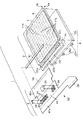
図1において、符号3は本発明に係る配線基板の一実施形態を示している。この配線基板3は、基板としてのFPC(Flexible Printed Circuit)33と、該FPC33上に実装された電子部品34と、同じくFPC33上に実装されたIC構造体としてのICパッケージ36とを有する。ICパッケージ36は、例えば、BGA(ball Grid Array)やCSP(Chip Sized Package)等によって構成できる。
【0042】
FPC33は、図3に示すように、可撓性を有するプラスチック製のベース材37の上に各種の膜要素を形成することによって形成される。具体的には、例えばポリイミドによって形成されたベース材37の実装側表面の上に、例えばCu(銅)によって配線38a及び端子39を形成し、端子39の回りにはレジスト41を塗布し、レジスト41を塗布した領域以外の領域には、例えばポリイミドによってカバーレイ42aを形成する。
【0043】
また、ベース材37の裏面側表面の上に、例えばCuによって配線38bを形成し、その上の全面に、例えばポリイミドによってカバーレイ42bを形成し、さらに、少なくともICパッケージ36に対応する領域に、例えばポリイミドによって補強膜43を形成する。
【0044】
図1において、レジスト41はICパッケージ36及び電子部品34を実装する領域内で、端子39が外部へ露出するように設けられる。また、カバーレイ42aはレジスト41を設けた領域以外のFPC33の全面に形成される。なお、カバーレイ42aやレジスト41は、液晶パネルとの接続部分や、コネクタとの接続部分には形成されない。また、FPC33の裏面側に設けられる配線38bのうちICパッケージ36の裏面に対応する部分38bbは、図3(a)に示すように、ICパッケージ36の全体を含むように広い面積で形成されている。
【0045】
この銅膜部分38bbは、ICパッケージ36の特性を正常状態に維持するための特性維持部材として機能するものであり、具体的には以下のような機能を有する。Cuはベース材37を形成するポリイミドよりも熱伝導率が高く、よって、銅膜部分38bbは、ICパッケージ36で発生する熱を外部へ放散する。また、Cuは遮光性を有するので、銅膜部分38bbは、ICパッケージ36が裏面側から光に晒されることを防止する。
【0046】
また、銅膜部分38bbはICパッケージ36よりも広く形成されるので、この銅膜部分38bbは、FPC33がICパッケージ36に対応する領域内で撓むことを防止することにより、ICパッケージ36にせん断力、曲げ力等といった外力が作用することを防止する。さらに、図1において、レジスト41が形成された領域に対応するFPC33の裏面に設けられた補強膜43(図3参照)は、ICパッケージ36に外力が作用することを、さらに防止する。なお、銅膜部分38bbの厚さは、例えば、30μm以下に設定する。
【0047】
図3において、表面側の配線38aと裏面側の配線38bとは、ベース材37を貫通するスルーホール44によって互いに導通する。これにより、FPC33の表裏両面を活用して複雑な回路を構成できる。また特に、ICパッケージ36の裏面に位置する銅膜部分38bbの所に形成されたスルーホール44は、銅膜部分38bbがICパッケージ36の発熱を外部へ放散する機能を、さらに一層高める。
【0048】
ICパッケージ36は、その底面、すなわち広域面に複数の端子を有する構造のICパッケージである。このICパッケージ36の具体的な構造は、種々考えられるが、例えば図4(a)に示すように、複数のハンダボール48を支持した面状テープ49を接着層47によってICチップ46の能動面に接合し、さらに、ICチップ46の端子(すなわち、パッド)とハンダボール48とをスルーホール52で導通することによって形成できる。なお、符号51は封止樹脂である。また、接着層47及び面状テープ49が透明である場合には、ICチップ46の能動面は外部の光に直接に晒されることになる。
【0049】
また、ICパッケージ36は、図4(b)に示すように、複数のハンダボール48を備えた配線板53を樹脂54によってICチップ46の能動面に接着し、さらにICチップ46のパッドとハンダボール48とをバンプ56で導通することによって形成できる。
【0050】
また、ICパッケージ36は、図4(c)に示すように、ICチップ46のパッド上にハンダ突起端子としての複数のハンダボール48を直接に形成し、さらにハンダボール48が外部へ露出するようにしてICチップ46を封止樹脂57で被覆することによって形成できる。封止樹脂57が透明である場合には、ICチップ46の能動面は外部の光に直接に晒されることになる。
【0051】
また、ICパッケージ36は、図15(a)に示したICパッケージ211や、図15(b)に示したICパッケージ212によって構成することもできる。なお、図4(a)、図4(b)及び図4(c)に示したICパッケージ36や、図15(a)に示したICパッケージ211や、図15(b)に示したICパッケージ212等といったICパッケージに共通する構造は、パッケージの側面に端子が引き出されるのではなくて、パッケージの底面、すなわち広域面にハンダボール48等といった端子が設けられることである。
【0052】
(配線基板の製造方法の実施形態)
図1の配線基板3は、例えば、図5に示すような製造方法によって作製できる。なお、これから説明する製造方法は本発明を理解するために例示されるものであり、本発明はその製造方法に限定されるものではない。
【0053】
工程P1において、図3のベース材37の表裏両面にCuを一様な厚さに積層し、さらに工程P2において、Cu層をパターニングして表面に配線38aを形成し、裏面に配線38bを形成する。次に、図5の工程P3において、図1のFPC33内の所定領域にレジスト41を塗布する。次に、図5の工程P2で形成した配線38a,38bの表面に、工程P4において、図1のFPC33の表裏両面内の所定領域にカバーレイ42a,42bを形成する。そしてさらに、必要に応じて、工程P5において配線上にAu(金)をメッキする。
【0054】
次に、図5の工程P6において、図1のFPC33上にハンダを印刷する。具体的には、FPC33の表面の全面又は必要な一部領域に金属製のマスクを載置した上で、クリームハンダをそのマスクの上に載せ、さらにスキージを用いてそのクリームハンダをマスク上で伸ばす。ここで用いるマスクには、ハンダを印刷したい個所に対応して開口が形成される。この開口は、通常、FPC33上の端子39に対応しており、従って、マスク上でハンダがスキージによって伸ばされると、開口を通してFPC33の端子39上にハンダが載せられる。
【0055】
今、図1のFPC33においてICパッケージ36を実装すべき領域に関するハンダ処理について説明する。ICパッケージ36を実装すべき領域は、図6(b)に示すように、レジスト41によって囲まれた領域となっている。この領域内には、ICパッケージ36の端子、例えば図4(a)のハンダボール48に対応して4×4=16個の端子39がマトリクス状に形成されている。これらの端子39には配線38aがつながっている。特に、内部領域に存在する4つの端子39から延びる配線38aは、外枠領域に存在する端子39のうちの互いに隣り合う2つの間を通って延びている。
【0056】
上記の16個の端子39の上にハンダを載せる際に用いられるマスク62は、図6(a)に示すように、FPC33上の各端子39に対応する位置に開口63を有する。このマスク62をFPC33上の所定位置に載置すると、各開口63はFPC33上の各端子39を外部へ露出させる位置に置かれる。本実施形態では、開口63の大きさは端子39よりも大きくなっている。従って、マスク62上にクリームハンダを載せ、さらにスキージを用いてそのクリームハンダを伸ばすと、各開口63を通して端子39上にハンダが供給され、そのハンダ64は図6(c)に示すように端子39の全面を覆うようにFPC33上に供給される。従来の実装方法によれば、ハンダは端子39と略同じ大きさか、又はそれよりも小さい領域で供給されていたので、マスク62をFPC33上に載せる位置が正規位置からずれると、端子39に関する導通面積が十分に確保できないという問題があった。これに対し、本実施形態によれば、ハンダ64が端子39よりも広い面積で印刷されるので、マスク63をFPC33上に載せる位置がずれたとしても十分な接触面積を確保できる。
【0057】
ところで、図6(b)において外枠領域に位置する端子39のように、2つの端子39の間に配線38aのような導電領域が形成される場合を考えると、開口63の面積を端子39よりも大きくしたとき、図6(c)に示すように、開口63を通して印刷したハンダ64が端子39に隣り合う導通領域、すなわち配線38aに被さることがある。
【0058】
このままの状態では、端子39と配線38aとがハンダ64によって短絡してしまうので、このハンダ付け構造を実用に供することはできない。しかしながら本実施形態では、今説明しているハンダ印刷工程(図5の工程P6)の後に、工程P8でリフロー処理を実行してこのハンダ64を溶融させることにしている。このようにハンダ64を溶融すると、リフロー条件を最適化することで、溶融したハンダ64は距離的に近い金属部材に引き寄せられるように移動する傾向にある。従って、図6(c)に示すハンダ64がリフロー処理を受けると、図6(d)に示すように、ハンダ64の一方64aは端子39へ引き寄せられ、ハンダ64の他方64bは配線38aへ引き寄せられ、結果的に、ハンダ64は2つの部分64a及び64bに分離する。これにより、端子39と配線38aとが短絡する心配はなくなる。
【0059】
図5のハンダ印刷工程P6が終了すると、工程P7において、図1の電子部品34及びICパッケージ36がFPC33上の所定位置にマウント、すなわち載せられる。すなわち、電子部品34の端子が端子39に載せられ、さらに、ICパッケージ36の各ハンダボール48が端子39に載せられる。
【0060】
その後、工程P8において、電子部品34及びICパッケージ36を載せたFPC33を、所定温度に昇温されているリフロー炉の中に入れて加熱し、これにより、電子部品34が載っているハンダ及びICパッケージ36のハンダボール48を溶かして、ハンダ付けを行う。このように、本実施形態の配線基板3に関しては、電子部品34とICパッケージ36とを1回のリフロー工程において同時にハンダ付けできるので、製造工程が簡略であり、製造コストも低くなる。
【0061】
なお、図1において、FPC33の一方の側の辺端には接続端子58が形成され、反対側の辺端には接続端子59が形成される。配線基板3は、これらの接続端子58及び59を介して外部の電子機器や、制御回路に接続される。
【0062】
(配線基板に関する変形例)
図1に示す配線基板3では、図示のような平面形状のFPC33を用いたが、FPCの平面形状はそれ以外の任意の形状とすることができる。また、FPCを基板として用いたが、ガラス基板やエポキシ基板等のように、可撓性を有しない性質の基板を用いることもできる。
【0063】
また、図6に示した実施形態では、2つの隣り合う端子39の間に別の導電領域である配線38aが設けられる場合を例示した。しかしながら本発明は、配線38aが存在することなく2つの端子39が隣り合う部分に、それらの端子39に被さるようにハンダを印刷する場合も含まれる。
【0064】
また、図6(a)に示した実施形態では、マスク62内に複数の開口63をマトリクス状に形成した。しかしながら、これに代えて、全ての開口63を含む広い長方形状又は正方形状の領域66を1つの開口として、全ての端子39を含む領域の全面にハンダを供給することもできる。
【0065】
(電気光学装置の実施形態)
以下、本発明に係る電気光学装置を液晶装置として実施した場合の実施形態を説明する。なお、これから説明する実施形態は本発明を理解するために例示されるものであり、本発明はその実施形態に限定されるものではない。
【0066】
図1において、電気光学装置としての液晶装置1は、液晶パネル2と、配線基板3とを有する。配線基板3は、上述した構成の配線基板を用いることができる。また、太陽光、室内光等といった外部光以外に照明装置を用いる場合には、液晶装置1は照明装置8を有する。図1の実施形態の場合、像が表示されるのは液晶パネル2の上面であり、よって、照明装置8は観察側の反対側から光を供給するバックライトとして機能する。
【0067】
液晶パネル2としては任意の方式の液晶パネルを採用できる。例えば、スイッチング素子を用いない単純マトリクス方式の液晶パネルや、TFD(Thin Film Diode)等といった2端子型のスイッチング素子を用いるアクティブマトリクス方式の液晶パネルや、TFT(Thin Film Transistor)等といった3端子型のスイッチング素子を用いるアクティブマトリクス方式の液晶パネル等を採用できる。今、液晶パネルとして単純マトリクス方式の液晶パネルを採用するものとすれば、液晶パネル2は以下のように構成される。
【0068】
液晶パネル2は、第1基板4aとそれに対向する第2基板4bとを有する。これらの基板4a,4bのうちの一方の表面上には、印刷等により、シール材6が略方形の枠状に形成される。そして、このシール材6により、第1基板4aと第2基板4bとが貼り合わされる。なお、シール材6の一部には、液晶注入用の開口7が予め設けられる。
【0069】
図2において、シール材6によって第1基板4aと第2基板4bとを貼り合わせると、それらの基板間には所定高さの間隙、すなわちセルギャップが形成され、そのセルギャップ内に液晶9が開口7(図1参照)を通して注入される。セルギャップ内への液晶9の注入が完了すると、開口7は樹脂等によって塞がれて、封止される。なお、液晶9が封入されたセルギャップは、通常、第1基板4a又は第2基板4bの表面に分散された複数の球形状のスペーサ11によってその寸法が保持される。
【0070】
第1基板4aは、ガラス、プラスチック等によって形成された基材12aを有し、この基材12aの液晶9側の表面に、例えばAl(アルミニウム)によって半透過反射膜13が形成される。この半透過反射膜13には、表示の最小単位である表示ドットに対応して、光透過用の複数の開口14がマトリクス状に並ぶ状態で形成される。これらの開口14は、例えば、フォトリソグラフィー処理及びエッチングによって形成できる。
【0071】
半透過反射膜13の上には、絶縁膜16が周知の成膜法、例えばスピンコート等によって形成される。また、絶縁膜16の上には、第1電極17aが、例えばITO(Indium Tin Oxide)を材料としてフォトリソグラフィー処理によって形成される。この第1電極17aは、図1に示すように複数の直線状の電極を互いに平行に並べることにより、図2の矢印D方向から見て全体としてストライプ状に形成される。なお、図1では、第1電極17aの配列状態を分かり易く示すために各直線状電極の間隔を実際よりも広く描いてあるが、実際には、第1電極17aは、より狭い間隔で多数本が基材12a上に形成される。
【0072】
図2において、第1電極17aの上には配向膜18aが、例えばポリイミドを材料として例えば印刷によって一様な厚さの膜として形成される。そして、この配向膜18aに配向処理、例えばラビング処理が施されて、液晶9の基板4a側の配向が決められる。また、基材12aの外側の表面には、偏光板19aが例えば貼着によって装着される。また。必要に応じて、偏光板19aと基材12aとの間に位相差板が設けられる。
【0073】
第1基板4aに対向する第2基板4bは、ガラス、プラスチック等によって形成された基材12bを有し、この基材12aの液晶9側の表面に、例えば顔料分散法、インクジェット法等によってカラーフィルタ21が形成される。このカラーフィルタ21は、例えば、R(赤)、G(緑)、B(青)の3原色や、C(シアン)、M(マゼンタ)、Y(イエロー)の3原色を矢印D方向から見て所定のパターン、例えばストライプ配列、デルタ配列、モザイク配列で配列することによって形成されている。カラーフィルタ21内の1つの色要素は、像を表示するための最小単位である表示ドットの1つに対応して配置される。そして、R,G,BやC,M,Yに対応する3つの色要素が1つのユニットとなって1つの画素が形成される。
【0074】
さらに、カラーフィルタ21の上には第2電極17bが、例えばITOを材料として例えばフォトリソグラフィー処理によって形成されている。この第2電極17bは、図1に示すように、上記第1電極17aと直交する方向に延びる複数の直線状電極を互いに平行に並べることにより、図2の矢印D方向から見て全体としてストライプ状に形成されている。なお、図1では、第2電極17bの配列状態を分かり易く示すために各直線状電極の間隔を実際よりも広く描いてあるが、実際には、第2電極17bは、より狭い間隔で多数本が基材12b上に形成される。
【0075】
さらに、第2電極17bの上には配向膜18bが、例えばポリイミドを材料として、例えば印刷によって一様な厚さの膜として形成される。そして、この配向膜18bに配向処理、例えばラビング処理が施されて、液晶9の基板4b側の配向が決められる。また、基材12bの外側の表面には、偏光板19bが例えば貼着によって装着される。このとき、偏光板19bの偏光軸は第1基板4a側の偏光板19aと異なる角度に設定される。
【0076】
図1において、第1基板4aは第2基板4bの外側へ張出す部分4cを有し、この張出し部4cの上に駆動用IC22a、22b、22cが、例えばACF(Anisotropic Conductive Film)を用いて実装されている。すなわち、本実施形態では、駆動用ICが液晶パネルの基板上に直接に実装される構造のCOG(Chip On Glass)方式の実装方法が採用されている。これらのICチップの入力端子は第1基板4aの張出し部4cの辺端に形成した外部接続端子23に接続する。
【0077】
張出し部4cの中央に位置する駆動用IC22bの出力端子は、第1基板4a上に形成した第1電極17aに直接に接続される。これにより、駆動用IC22bは第1電極17aを駆動する。図2に示すように、シール材6の中には複数の球状又は円柱状の導通材24が分散状態で含まれる。図1において、張出し部4cの両脇領域に実装された駆動用IC22a及び22cは、それらの導通材24を介して、第2基板4b上に形成された第2電極17bに接続される。これにより、駆動用IC22a及び22cは第2電極17bを駆動する。
【0078】
図1において、照明装置8は、プラスチック等によって形成された導光体26と、この導光体26の光取込み面26aに対向して配置された発光源としてのLED(Light Emitting Diode)27とを有する。図2に示すように、LED27は、LED基板28によって支持されて所定位置に配置される。また、導光体26の液晶パネル2側の表面、すなわち光出射面26bには拡散シート29が、例えば貼着によって装着される。また、導光体26の液晶パネル2と反対側の表面には反射シート31が、例えば貼着によって装着される。また、照明装置8の全体は、緩衝部材32を介して液晶パネル2に装着される。
【0079】
液晶パネル2は以上のように構成されているので、図2において、第2基板4bの外側、すなわち観察側の光が強い場合には、その光は、第2基板4bを通過し、液晶9を通過し、さらに半透過反射膜13で反射して、再び液晶9へ供給される。一方、図1において、駆動用IC22a、22b、22cは第1電極17aと第2電極17bとの間に印加される電圧を、表示ドットごとに制御して液晶9の配向を表示ドットごとに制御する。半透過反射膜13で反射して液晶9の層へ供給された光は、液晶9の配向に従って変調され、その変調された光が偏光板19bを選択的に通過することにより、観察側に希望の像が表示される。本実施形態では光路上にカラーフィルタ21を設けてあるので、表示され像はカラー像である。こうして反射型の表示が行われる。
【0080】
他方、観察側の光が弱い場合にはLED27を点灯させる。このとき、LED27から出た点状又は線状の光は、導光体26の光取込み面26aから当該導光体26の内部へ導入され、導光体26の内部を伝播した後、光出射面26bから外部へ面状に出射する。この光は、第1基板4aを通過し、さらに半透過反射膜13に設けた開口14を通過して、液晶9の層へ供給される。この光が、液晶9の配向に従って変調されて外部に像として表示されることは、反射型の場合と同じである。こうして、透過型の表示が行われる。
【0081】
図1において、FPC33の液晶パネル2側の辺端には接続端子58が形成され、反対側の辺端には接続端子59が形成される。そして、接続端子58が形成されたFPC33の辺端部は、ACF61によって第1基板4aの張出し部4cの辺端部に熱圧着によって接合される。ACF61は、熱可塑性、熱硬化性、あるいは紫外線硬化性の樹脂中に多数の導電粒子を分散させることによって形成されており、第1基板4aとFPC33とはACF61を形成する樹脂によって接着され、さらにFPC33上の端子58と第1基板4a上の端子23とがACF61内の導電粒子によって導通される。
【0082】
配線基板3の接続端子59は図示しない外部制御回路、例えば、携帯電話機、携帯情報端末機等といった電子機器に含まれる制御回路に接続される。外部制御回路から端子59を介して配線基板3へ信号が供給されると、電子部品34及びICパッケージ36が所定の機能を奏し、それ故、駆動用IC22a、22b、22cへ所定の信号が供給され、これにより、既述した液晶パネル2による表示が行われる。
【0083】
(電気光学装置の製造方法の実施形態)
図1の液晶装置1は、例えば、図7に示す製造方法によって作製できる。なお、これから説明する製造方法は本発明を理解するために例示されるものであり、本発明はその製造方法に限定されるものではない。
【0084】
図7において、工程P11から工程P15で示す一連の工程が図2の第1基板4aを製造するための工程である。また、工程P21から工程P26に示す一連の工程が図2の第2基板4bを製造するための工程である。
【0085】
なお、本実施形態では、図2に示す第1基板4a及び第2基板4bを1個ずつ形成するのではなく、図8(a)に示すように、第1基板4aを複数形成できる面積を持った大面積、すなわち大判のマザー基材4a’に第1基板4aの複数分の液晶パネルパターンを形成するものとする。また、図8(b)に示すように、大判のマザー基材4b’に第2基板4bの複数分の液晶パネルパターンを形成するものとする。
【0086】
まず、図7の工程P11において、図8(a)に示すマザー基材4a’の表面に半透過反射膜13(図2参照)を、例えばアルミニウム、アルミニウム合金、銀合金等を材料として、例えばフォトリソグラフィー法を用いたパターニング法によって形成する。このとき、個々の表示ドット領域に対応して開口14が形成される。次に、工程P12で、絶縁膜16を周知の成膜法、例えばスピンコート法によって形成する。
【0087】
次に、図7の工程P13において、図2の第1電極17aを、例えばITOを材料として周知のパターニング法、例えばフォトリソグラフィー法及びエチング処理によって形成し、さらに工程P14において図2の配向膜18aを例えばポリイミドを材料として塗布及び焼成によって形成し、さらに工程P15においてその配向膜18aに配向処理、例えばラビング処理を施して液晶の配向を決める。以上により、図8(a)のマザー基材4a’上に図2の第1基板4aの複数分のパターンが形成される。
【0088】
一方、図7の工程P21において、図8(b)に示すマザー基材4b’の表面に図2のカラーフィルタ21を、例えば顔料分散法、インクジェット法、その他任意の手法によって所定のパターンで形成し、さらに、工程P22において、図2の第2電極17bを、例えばITOを材料として周知のパターニング法、例えばフォトリソグラフィー法及びエチング処理によって形成する。さらに、工程P23において図2の配向膜18bを、例えばポリイミドを材料として塗布及び焼成によって形成し、さらに工程P24においてその配向膜18bに配向処理、例えばラビング処理を施して液晶の配向を決める。
【0089】
次に、工程P25において、図2のシール材6を印刷等によってマザー基材4b’の表面に形成し、さらに工程P26において図2のスペーサ11を分散する。以上により、図8(b)のマザー基材4b’上に図2の第2基板4bの複数分のパターンが形成される。
【0090】
以上により、第1基板4aを複数有するマザー基材4a’及び第2基板4bを複数有するマザー基材4b’が形成されると、工程P31において、それらのマザー基材4a’及び4b’をシール材6を間に挟んで貼り合わせる。これにより、図2の液晶パネル2を複数内蔵する大判のパネル構造体が形成される。
【0091】
次に、工程P32において、上記の大判のパネル構造体に対して1回目の切断、すなわち1次ブレイクを行って、各液晶パネル部分の液晶注入用開口7(図1参照)が外部に露出した状態の1列に長いパネル構造体、いわゆる短冊状のパネル構造体が形成される。次に、以上のようにして外部へ露出した液晶注入用開口7を通して、短冊状パネル構造体内の各液晶パネル部分の内部に液晶を注入し、さらにその後、液晶注入用開口7を樹脂等によって封止する。
【0092】
次に、工程34で、液晶封入後の短冊状のパネル構造体に対して2回目の切断、すなわち2次ブレイクを行って、図1に示す液晶パネル2を個々に分断する。分断された液晶パネル2は工程P35によって洗浄されて不要な液晶等を取り除かれ、その後、工程P36において偏光板19a,19bが例えば貼着によって装着される。その後、工程P37において、図1の駆動用IC22a、22b、22cを第1基板4aの張出し部4c上に実装し、さらに照明装置8を液晶パネル2へ取り付ける。
【0093】
以上のような液晶パネルの製造工程とは別に、工程P38において配線基板の製造工程を実行する。これは、例えば、図5に示した一連の工程によって実現される。従って、配線基板製造工程P38により、図1に示した配線基板3が製造される。こうして配線基板3が製造されると、図7の工程P39において、図1に示すように、配線基板3がACF61を用いて第1基板4aの張出し部4cの辺端部に接続される。さらに、工程P40において、図1の照明装置8を液晶パネル2に装着することにより、図1の液晶装置1が完成する。
【0094】
本実施形態の液晶装置1に関しては、その内部に含まれる配線基板3が図5に示した製造方法によって形成される。すなわち、図6(a)のような大きな開口63又は66を備えたマスク62を用いてハンダ印刷を行う工程を有する製造方法によって配線基板3が形成される。これにより、配線基板3においてICパッケージ36を信頼性高く実装することができ、それ故、ICに関する特性を長期間にわたって正常に維持できる。
【0095】
(変形例)
以上の説明では、スイッチング素子を用いない単純マトリクス構造の液晶装置を例示したが、本発明は、2端子型のスイッチング素子を各表示ドットに付設する構造のアクティブマトリクス構造の液晶装置や、3端子型のスイッチング素子を各表示ドットに付設する構造のアクティブマトリクス型の液晶装置にも適用できる。
【0096】
また、本発明は、液晶装置以外の電気光学装置に対しても適用できる。このような電気光学装置としては、例えば、電気光学物質として有機EL(Electro Luminescence)を用いるEL装置や、電気光学物質として希薄なガスを用いてこのガス中で発生するプラズマ放電を利用する構造のプラズマ装置や、無機EL装置や、電気泳動ディスプレイ装置や、フィールドエミッションディスプレイ装置(電界放出表示装置)等が考えられる。
【0097】
(電子機器の実施形態)
以下、本発明に係る電子機器を実施形態を挙げて説明する。なお、この実施形態は本発明の一例を示すものであり、本発明はこの実施形態に限定されるものではない。
【0098】
図9は、本発明に係る電子機器の一実施形態を示している。ここに示す電子機器は、表示情報出力源101、表示情報処理回路102、電源回路103、タイミングジェネレータ104及び液晶装置105によって構成される。そして、液晶装置105は液晶パネル107及び駆動回路106を有する。
【0099】
表示情報出力源101は、RAM(Random Access Memory)等といったメモリや、各種ディスク等といったストレージユニットや、ディジタル画像信号を同調出力する同調回路等を備え、タイミングジェネレータ104により生成される各種のクロック信号に基づいて、所定フォーマットの画像信号等といった表示情報を表示情報処理回路102に供給する。
【0100】
次に、表示情報処理回路102は、増幅・反転回路や、ローテーション回路や、ガンマ補正回路や、クランプ回路等といった周知の回路を多数備え、入力した表示情報の処理を実行して、画像信号をクロック信号CLKと共に駆動回路106へ供給する。ここで、駆動回路106は、走査線駆動回路(図示せず)やデータ線駆動回路(図示せず)と共に、検査回路等を総称したものである。また、電源回路103は、上記の各構成要素に所定の電源電圧を供給する。
【0101】
液晶装置105は、例えば、図1に示した液晶装置1と同様に構成できる。また、その液晶装置105は、例えば図7に示す製造方法によって製造できる。また、液晶装置1に含まれる図1の配線基板3は、例えば図5に示す製造方法によって製造できる。図5に示す製造方法のハンダ印刷工程P6で用いる図6(a)のマスク62はFPC33上の端子39よりも広い面積の開口63を有するので、この開口63を通して基板33上へ印刷されたハンダは端子39に対して十分な接触面積を確保できる。
【0102】
図10は、本発明に係る電子機器の他の実施形態であるモバイル型のパーソナルコンピュータを示している。ここに示すパーソナルコンピュータ110は、キーボード112を備えた本体部114と、液晶表示ユニット116とから構成されている。
【0103】
この液晶表示ユニット116は、例えば図1に示した液晶装置1を表示部として用いて構成できる。また、その液晶装置1は、例えば図7に示す製造方法によって製造できる。また、液晶装置1に含まれる図1の配線基板3は、例えば図5に示す製造方法によって製造できる。図5に示す製造方法のハンダ印刷工程P6で用いる図6(a)のマスク62はFPC33上の端子39よりも広い面積の開口63を有するので、この開口63を通して基板33上へ印刷されたハンダは端子39に対して十分な接触面積を確保できる。
【0104】
図11は、本発明に係る電子機器のさらに他の実施形態である携帯電話機を示している。ここに示す携帯電話機120は、複数の操作ボタン122と、受話口124と、送話口126と、液晶表示ユニット128とを有する。この液晶表示ユニット128は、例えば図1に示した液晶装置1を用いて構成できる。また、その液晶装置1は、例えば図7に示す製造方法によって製造できる。また、液晶装置1に含まれる図1の配線基板3は、例えば図5に示す製造方法によって製造できる。図5に示す製造方法のハンダ印刷工程P6で用いる図6(a)のマスク62はFPC33上の端子39よりも広い面積の開口63を有するので、この開口63を通して基板33上へ印刷されたハンダは端子39に対して十分な接触面積を確保できる。
【0105】
図12は、本発明に係る電子機器のさらに他の実施形態であるデジタルスチルカメラであって、液晶装置をファインダとして用いるものを示している。通常のカメラは、被写体の光像によってフィルムを感光するのに対し、デジタルスチルカメラ130は、被写体の光像をCCD(Charge Coupled Device)等といった撮像素子により光電変換して撮像信号を生成するものである。
【0106】
デジタルスチルカメラ130におけるケース131の背面には、液晶表示ユニット132が設けられ、CCDによる撮像信号に基づいて、表示を行う構成となっている。このため、液晶表示ユニット132は、被写体を表示するファインダとして機能する。
【0107】
ケース131の前面側(図においては裏面側)には、光学レンズやCCD等を含んだ受光ユニット133が設けられている。撮影者が液晶表示ユニット132に表示された被写体像を確認して、シャッタボタン134を押下すると、その時点におけるCCDの撮像信号が、回路基板135のメモリに転送されてそこに格納される。
【0108】
ケース131の側面には、ビデオ信号出力端子136と、データ通信用の入出力端子137とが設けられている。ビデオ信号出力端子136にはテレビモニタ138が必要に応じて接続され、また、データ通信用の入出力端子137にはパーソナルコンピュータ139が必要に応じて接続される。回路基板135のメモリに格納された撮像信号は、所定の操作によって、テレビモニタ138や、パーソナルコンピュータ139に出力される。
【0109】
液晶表示ユニット132は、例えば図1に示した液晶装置1を用いて構成できる。また、その液晶装置1は、例えば図7に示す製造方法によって製造できる。また、液晶装置1に含まれる図1の配線基板3は、例えば図5に示す製造方法によって製造できる。図5に示す製造方法のハンダ印刷工程P6で用いる図6(a)のマスク62はFPC33上の端子39よりも広い面積の開口63を有するので、この開口63を通して基板33上へ印刷されたハンダは端子39に対して十分な接触面積を確保できる。
【0110】
図13は、本発明に係る電子機器のさらに他の実施形態である腕時計型電子機器を示している。ここに示す腕時計型電子機器140は、時計本体141に支持された表示部としての液晶表示ユニット142を有し、この液晶表示ユニット142は、時計本体141の内部に設けた制御回路143によって制御されて、時刻、日付等を情報として表示する。
【0111】
この液晶表示ユニット142は、例えば図1に示した液晶装置1を用いて構成できる。また、その液晶装置1は、例えば図7に示す製造方法によって製造できる。また、液晶装置1に含まれる図1の配線基板3は、例えば図5に示す製造方法によって製造できる。図5に示す製造方法のハンダ印刷工程P6で用いる図6(a)のマスク62はFPC33上の端子39よりも広い面積の開口63を有するので、この開口63を通して基板33上へ印刷されたハンダは端子39に対して十分な接触面積を確保できる。
【0112】
図14は、本発明に係る電子機器のさらに他の実施形態であるPDA(Personal Digital Assistant:パーソナル・デジタル・アシスタント:携帯型情報端末装置)を示している。ここに示すPDA150は、接触方式、いわゆるタッチパネル方式の入力装置151をその正面パネル上に有する。この入力装置151は透明であり、その下には表示部としての液晶装置152が配置されている。
【0113】
使用者は、付属のペン型入力具153を入力装置151の入力面に接触させることにより、液晶装置152に表示されたボタン、その他の表示を選択したり、文字、図形等を描いたりして、必要な情報を入力する。この入力情報に対してPDA150内のコンピュータによって所定の演算が行われ、その演算の結果が液晶装置152に表示される。
【0114】
液晶装置152は、例えば図1に示した液晶装置1を用いて構成できる。また、その液晶装置1は、例えば図7に示す製造方法によって製造できる。また、液晶装置1に含まれる図1の配線基板3は、例えば図5に示す製造方法によって製造できる。図5に示す製造方法のハンダ印刷工程P6で用いる図6(a)のマスク62はFPC33上の端子39よりも広い面積の開口63を有するので、この開口63を通して基板33上へ印刷されたハンダは端子39に対して十分な接触面積を確保できる。
【0115】
(変形例)
なお、電子機器としては、以上に説明したパーソナルコンピュータや、携帯電話機や、デジタルスチルカメラや、腕時計型電子機器や、PDAの他にも、液晶テレビや、ビューファインダ型又はモニタ直視型のビデオテープレコーダや、カーナビゲーション装置や、ページャや、電子手帳や、電卓や、ワードプロセッサや、ワークステーションや、テレビ電話機や、POS端末器等が挙げられる。
【0116】
【発明の効果】
本発明によれば、FPC等といった基板上にマスクの開口を通して供給されるハンダの面積は、基板上の端子よりも大きくなるので、仮にマスクが正規位置からずれて基板の上に置かれた場合でも、基板上の端子とそれに供給されたハンダとの間の接触面積を十分に確保できる。
【図面の簡単な説明】
【図1】 本発明に係る配線基板及び電気光学装置のそれぞれの一実施形態を示す斜視図である。
【図2】 図1に示す電気光学装置の主要部分である液晶パネルの断面図である。
【図3】 図1に示す配線基板の断面構造を示す断面図である。
【図4】 本発明で用いるICパッケージの複数の実施形態を示す図である。
【図5】 本発明に係る配線基板の製造方法の一実施形態を示す工程図である。
【図6】 本発明に係るマスク及びそれを用いて印刷されたハンダの一例を示す図である。
【図7】 本発明に係る電気光学装置の製造方法の一実施形態を示す工程図である。
【図8】 図7の製造方法で用いるマザー基板の一例を示す平面図である。
【図9】 本発明に係る電子機器の一実施形態を示すブロック図である。
【図10】 本発明に係る電子機器の他の実施形態を示す斜視図である。
【図11】 本発明に係る電子機器のさらに他の実施形態を示す斜視図である。
【図12】 本発明に係る電子機器のさらに他の実施形態を示す斜視図である。
【図13】 本発明に係る電子機器のさらに他の実施形態を示す斜視図である。
【図14】 本発明に係る電子機器のさらに他の実施形態を示す斜視図である。
【図15】 本発明で用いるICパッケージの他の複数の実施形態を示す図である。
【図16】 従来の配線基板の主要部分の断面構造を示す断面図である。
【符号の説明】
1:液晶装置(電気光学装置)、2:液晶パネル、3:配線基板、4a,4b:基板、6:シール材、8:照明装置、9:液晶(電気光学物質)、12a,12b:基材、13:半透過反射板、14:開口、17a,17b:電極、33:FPC(基板)、34:電子部品、36:ICパッケージ、37:ベース材、38a,38b:配線、38bb:銅膜部材、39:基板側端子、41:レジスト、42a,42b:カバーレイ、43:補強膜、44:スルーホール、46:ICチップ、48:ハンダボール(ICパッケージに備わる端子)、62:マスク、63:開口、64:ハンダ、66:開口、110:パーソナルコンピュータ(電子機器)、120:携帯電話機(電子機器)、130:デジタルスチルカメラ(電子機器)、140:腕時計型電子機器(電子機器)、150:PDA(電子機器)[0001]
BACKGROUND OF THE INVENTION
The present invention includes (1) a mask used when solder is printed on a substrate, (2) a method of manufacturing a wiring substrate using the mask, (3) a wiring substrate manufactured by the manufacturing method, (4) ▼ Electro-optical device manufacturing method using the wiring board manufacturing method, (5) Electro-optical device manufactured by the electro-optical device manufacturing method, and (6) Electronic equipment using the electro-optical device manufacturing method And (7) an electronic device manufactured by the manufacturing method.
[0002]
[Prior art]
Conventionally, as a wiring board formed by mounting an IC chip on a base material, a structure in which an IC chip is mounted on a base material using an ACF (Anisotropic Conductive Film) is known ( For example, see Patent Document 1). The ACF is formed, for example, by dispersing a plurality of
[0003]
When the
[0004]
By this thermocompression bonding, the main body portion of the
[0005]
By the way, in the wiring board formed using the ACF 201, electronic components such as a capacitor and a resistor are usually mounted in addition to the
[0006]
As described above, when mounting both an electronic component such as a capacitor and an IC chip on a base material, the above-described conventional wiring board using the ACF 201 has two processes: a thermocompression process for the ACF 201 and the solder reflow process. There is a problem that the manufacturing cost becomes high.
[0007]
Further, considering the case where the solder reflow process is performed after the
[0008]
[Patent Document 1]
Japanese Patent Laid-Open No. 10-84002 (5th page, FIG. 1)
[0009]
[Problems to be solved by the invention]
Recently, an IC package having a structure in which a plurality of terminals are provided on the bottom surface of a package, such as a BGA (ball grid array) and a CSP (Chip Sized Package), has been put to practical use. As these BGAs and CSPs, for example, those having the structure shown in FIGS. 15A and 15B are known.
[0010]
Specifically, the
[0011]
15B, the
[0012]
In the IC package shown in FIGS. 15A and 15B, the
[0013]
A structure common to IC packages such as the
[0014]
When an IC package having terminals on the bottom surface of a package such as a BGA is mounted on a substrate, generally, solder is placed on a plurality of terminals formed on the substrate, and each terminal of the IC package is placed thereon. In this way, the IC package is aligned and mounted on the substrate, that is, mounted, and the solder is melted by solder reflow processing or the like to solder the IC package onto the substrate.
[0015]
When printing solder on a plurality of terminals on a substrate, conventionally, a mask having an opening at a position corresponding to the terminals is placed on the substrate, and further, solder such as cream solder is placed on the mask with a squeegee. The solder is supplied onto each substrate side terminal through the opening. In general, the size of the opening of the mask is set to be the same as or smaller than the substrate-side terminal. This is to prevent a short circuit from occurring even when the position where the solder is printed deviates from the normal position.
[0016]
However, as described above, when the size of the mask opening is set to be the same as or smaller than the terminal on the substrate, the solder supplied to the substrate side terminal through the mask opening and the substrate side terminal The contact area, i.e., the conduction area, becomes small, and in some cases, a conduction failure may occur.
[0017]
The present invention has been made in view of the above problems, and when printing solder on a plurality of terminals formed on a substrate, the contact area between the solder and the terminals is always sufficiently secured. The purpose is to be able to.
[0018]
[Means for Solving the Problems]
In order to achieve the above object, a mask according to the present invention is a mask used when solder is printed on a plurality of terminals formed on a substrate so as to correspond to a plurality of terminals provided in an IC package. A conductive region is formed between at least a pair of substrate-side terminals among the plurality of substrate-side terminals provided on the substrate, and the opening is formed between the pair of substrate-side terminals. It has a size that spans one substrate-side terminal and the conductive region, and the conductive region is a wiring extending from the one substrate-side terminal.
In the above, a part of the solder may cover the one substrate side terminal and the conductive region.
In the above, the substrate is subjected to solder reflow processing.
The method for manufacturing a wiring board according to the present invention includes a step of supplying solder through openings of a mask onto each of a plurality of terminals on the substrate side formed on the board so as to correspond to the plurality of terminals provided in the IC package. In the method for manufacturing a substrate, a conductive region is formed between at least a pair of the plurality of substrate-side terminals provided on the substrate, and the opening includes one substrate-side terminal of the pair of substrate-side terminals and the conductive region. The conductive region is a wiring extending from the one substrate side terminal, and the solder is supplied to a region wider than the one substrate side terminal with respect to the one substrate side terminal. It is characterized by that.
The above-described method for manufacturing a wiring board further includes a solder reflow process for melting the solder supplied onto the board.
In the method for manufacturing a wiring board, in the step of supplying the solder, a part of the solder covers the one substrate-side terminal and the conductive region.
In the above method for manufacturing a wiring board, the solder is supplied onto the substrate so as to cover all of the one substrate-side terminal and to cover part or all of the width direction of the conductive region. Features.
A wiring board according to the present invention is manufactured using the method for manufacturing a wiring board described in any one of the above.
A method for manufacturing an electro-optical device according to the present invention includes a step of performing the method for manufacturing a wiring board described in any one of the above.
An electro-optical device according to the present invention is manufactured using the above-described electro-optical device manufacturing method.
According to another aspect of the invention, there is provided an electronic apparatus manufacturing method including a step of performing the electro-optical device manufacturing method.
An electronic apparatus according to the present invention is manufactured using the above-described electronic apparatus manufacturing method.
(1) In order to achieve the above object, a mask according to the present invention is a mask used when solder is printed on a plurality of terminals formed on a substrate so as to correspond to a plurality of terminals provided in an IC package. And having an opening for passing solder, the opening being larger than the terminal.
[0019]
According to this configuration, the area of the solder (for example,
[0020]
(2) It is desirable that the mask having the above-described configuration be used for a substrate subjected to solder reflow processing. Here, the solder reflow process is a process in which the substrate on which the IC package is mounted is placed in a reflow furnace heated to a predetermined high temperature, and the solder is melted by this process. The IC package is soldered on the substrate.
[0021]
When a substrate with solder supplied to a larger area than the terminal on the substrate is heated in a reflow furnace, the solder supplied over a larger area than the terminal on the terminal of the substrate shrinks toward that terminal. And become a mass. Therefore, it is possible to prevent the solder from greatly protruding from the terminal on the substrate after the soldering process is completed.
[0022]
(3) The mask according to the present invention is used for a substrate in which a
[0023]
In this way, the solder supplied on the substrate is placed in a region wider than the terminal 39 as shown by
[0024]
(4) Regarding a wiring board to which the mask having the above-described configuration is applied, a wiring extending from one board-side terminal may be disposed as a conductive region between a pair of board-side terminals adjacent to each other. In this case, it is desirable that the opening in the mask has a size that extends over the wiring and one of the substrate-side terminals. However, when the pitch between the terminals is wide, the opening in the mask does not cover the conductive region.
[0025]
(5) Next, in the method for manufacturing a wiring board according to the present invention, solder is provided through a mask opening on each of a plurality of board-side terminals formed on the board so as to correspond to the plurality of terminals provided in the IC package. In the method of manufacturing a wiring board having a step of supplying the solder, the solder is supplied to each of the board-side terminals in a wider area than the board-side terminal.
[0026]
According to this method of manufacturing a wiring board, since the solder is supplied to a wider area than the terminals, even if the mask is shifted from the normal position and placed on the board, the terminals on the board and the solder supplied thereto A sufficient contact area can be secured.
[0027]
(6) It is desirable that the method for manufacturing a wiring board having the above-described configuration further includes a solder reflow process for melting the solder supplied on the board. When a substrate with solder supplied to a larger area than the terminal on the substrate is heated in a reflow furnace, the solder supplied over a larger area than the terminal on the terminal of the substrate shrinks toward that terminal. And become a mass. Therefore, it is possible to prevent the solder from greatly protruding from the terminal on the substrate after the soldering process is completed.
[0028]
(7) Next, the method of manufacturing a wiring board according to the present invention can be applied to a wiring board in which a conductive region is formed between at least a pair of a plurality of board-side terminals. In that case, in the step of supplying the solder, the solder may be supplied onto the substrate so as to cover all of one substrate-side terminal and to cover part or all of the conductive region in the width direction. it can.
[0029]
If it carries out like this, all the said board | substrate side terminals can be reliably covered with solder. In addition, the solder arranged across the board-side terminal and the conductive area initially contracts toward the board-side terminal and the conductive area after the soldering by the solder reflow process or the like. Therefore, there is no short circuit between them. However, when the pitch between the terminals is wide, it is not always necessary to cover the conductive region.
[0030]
(8) Regarding a wiring board to which the method for manufacturing a wiring board having the above configuration is applied, a wiring extending from one board side terminal may be disposed as a conductive region between a pair of board side terminals adjacent to each other. . In this case, it is desirable that the solder supplied on the substrate is disposed on the substrate in a size that spans the wiring and one of the substrate-side terminals.
[0031]
If it carries out like this, all the said board | substrate side terminals can be reliably covered with solder. In addition, the solder arranged across the board-side terminal and the wiring is initially contracted toward the board-side terminal and the wiring after the soldering by the solder reflow process or the like. Since they are separated, there is no short circuit between them.
[0032]
(9) Next, the wiring board according to the present invention is manufactured using the method for manufacturing a wiring board having the above-described configuration. According to the method for manufacturing a wiring board having the configuration described above, a sufficient amount of solder can be interposed between the terminals of the IC package and the terminals on the board. With respect to the wiring board of the present invention, it is possible to reliably prevent the occurrence of poor conduction with respect to the IC package.
[0033]
(10) Next, a method for manufacturing an electro-optical device according to the present invention includes a step of performing the method for manufacturing a wiring board having the above-described configuration. As the electro-optical device here, a liquid crystal device using liquid crystal as an electro-optical material, an EL device using organic EL (Electro Luminescence) as an electro-optical material, or a rare gas as an electro-optical material is generated in the gas. A plasma apparatus using plasma discharge and other various apparatuses are conceivable.
[0034]
According to the method for manufacturing a wiring board having the configuration described above, a sufficient amount of solder can be interposed between the terminals of the IC package and the terminals on the board. With respect to the wiring board, it is possible to reliably prevent the occurrence of poor conduction with respect to the IC package, and therefore, a highly reliable electro-optical device can be manufactured.
[0035]
(11) Next, an electro-optical device according to the present invention is manufactured by using the above-described electro-optical device manufacturing method. Accordingly, it is possible to provide a highly reliable electro-optical device that has no conduction failure with respect to the IC package.
[0036]
(12) Next, a method for manufacturing an electronic apparatus according to the invention includes a step of performing a method for manufacturing an electro-optical device having the above-described configuration. Thereby, it is possible to provide a highly reliable electronic device that has no conduction failure with respect to the IC package.
[0037]
(13) Next, an electronic device according to the present invention is manufactured using the method for manufacturing an electronic device having the above-described configuration. Thereby, it is possible to provide a highly reliable electronic device that has no conduction failure with respect to the IC package.
[0038]
(14) The method for manufacturing an electro-optical device according to the invention may further include a step of forming a liquid crystal layer. Thereby, a liquid crystal device can be created as an electro-optical device. More specifically, an electrode is formed on one substrate, a counter electrode is formed on a substrate opposite to the one substrate, the pair of substrates are bonded to each other with a cell gap interposed therebetween, and the cell gap is formed. A liquid crystal layer is formed between the pair of substrates by enclosing the liquid crystal therein.
[0039]
According to the method for manufacturing an electro-optical device according to the present invention, the wiring board formed using the solder printing mask according to the present invention is connected to one or both of the pair of substrates constituting the liquid crystal device. . With respect to the wiring board formed in this way, it is possible to reliably prevent the occurrence of a conduction failure with respect to the IC package, so that a highly reliable electro-optical device can be manufactured.
[0040]
DETAILED DESCRIPTION OF THE INVENTION
(Embodiment of wiring board)
Hereinafter, a wiring board according to the present invention will be described with reference to an embodiment thereof. In addition, embodiment described below is illustrated in order to understand this invention, and this invention is not limited to that embodiment.
[0041]
In FIG. 1, the code |
[0042]
As shown in FIG. 3, the
[0043]
Further, a
[0044]
In FIG. 1, a resist 41 is provided so that the
[0045]
The copper film portion 38bb functions as a characteristic maintaining member for maintaining the characteristics of the
[0046]
Further, since the copper film portion 38bb is formed wider than the
[0047]
In FIG. 3, the front-
[0048]
The
[0049]
Further, as shown in FIG. 4B, the
[0050]
Further, as shown in FIG. 4C, the
[0051]
Further, the
[0052]
(Embodiment of manufacturing method of wiring board)
The
[0053]
In step P1, Cu is laminated on both the front and back surfaces of the
[0054]
Next, in step P6 in FIG. 5, solder is printed on the
[0055]
Now, the soldering process relating to the area where the
[0056]
As shown in FIG. 6A, the
[0057]
By the way, considering the case where a conductive region such as a
[0058]
In this state, since the terminal 39 and the
[0059]
When the solder printing process P6 in FIG. 5 is completed, in step P7, the
[0060]
Thereafter, in Step P8, the
[0061]
In FIG. 1, a
[0062]
(Modifications related to wiring boards)
In the
[0063]
In the embodiment illustrated in FIG. 6, the case where the
[0064]
In the embodiment shown in FIG. 6A, a plurality of
[0065]
(Embodiment of electro-optical device)
Hereinafter, embodiments in which the electro-optical device according to the invention is implemented as a liquid crystal device will be described. In addition, embodiment described below is illustrated in order to understand this invention, and this invention is not limited to that embodiment.
[0066]
In FIG. 1, a liquid crystal device 1 as an electro-optical device includes a
[0067]
As the
[0068]
The
[0069]
In FIG. 2, when the
[0070]
The
[0071]
On the transflective film 13, an insulating
[0072]
In FIG. 2, an alignment film 18a is formed on the
[0073]
The
[0074]
Further, the
[0075]
Furthermore, an
[0076]
In FIG. 1, the
[0077]
The output terminal of the driving
[0078]
In FIG. 1, the illuminating
[0079]
Since the
[0080]
On the other hand, when the light on the observation side is weak, the
[0081]
In FIG. 1, a
[0082]
The
[0083]
(Embodiment of manufacturing method of electro-optical device)
The liquid crystal device 1 shown in FIG. 1 can be manufactured, for example, by the manufacturing method shown in FIG. In addition, the manufacturing method demonstrated from now on is illustrated in order to understand this invention, and this invention is not limited to the manufacturing method.
[0084]
In FIG. 7, a series of steps indicated by steps P11 to P15 is a step for manufacturing the
[0085]
In the present embodiment, the
[0086]
First, in the process P11 of FIG. 7, the transflective film 13 (see FIG. 2) is used on the surface of the
[0087]
Next, in step P13 of FIG. 7, the
[0088]
On the other hand, in step P21 of FIG. 7, the
[0089]
Next, in step P25, the sealing material 6 of FIG. 2 is formed on the surface of the
[0090]
As described above, when the
[0091]
Next, in step P32, the large-sized panel structure is cut for the first time, that is, a primary break is performed, and the liquid crystal injection openings 7 (see FIG. 1) of the liquid crystal panel portions are exposed to the outside. A long panel structure, that is, a so-called strip-shaped panel structure is formed in one row of states. Next, liquid crystal is injected into each liquid crystal panel portion in the strip-shaped panel structure through the liquid crystal injection opening 7 exposed to the outside as described above, and then the liquid crystal injection opening 7 is sealed with resin or the like. Stop.
[0092]
Next, in
[0093]
Separately from the manufacturing process of the liquid crystal panel as described above, the manufacturing process of the wiring board is executed in process P38. This is realized, for example, by a series of steps shown in FIG. Therefore, the
[0094]
With respect to the liquid crystal device 1 of the present embodiment, the
[0095]
(Modification)
In the above description, a liquid crystal device having a simple matrix structure that does not use a switching element has been exemplified. However, the present invention is a liquid crystal device having an active matrix structure in which a two-terminal switching element is attached to each display dot, or a three-terminal structure. The present invention can also be applied to an active matrix type liquid crystal device having a structure in which a type switching element is attached to each display dot.
[0096]
The present invention can also be applied to electro-optical devices other than liquid crystal devices. As such an electro-optical device, for example, an EL device using organic EL (Electro Luminescence) as an electro-optical material, or a structure using a plasma discharge generated in this gas using a dilute gas as an electro-optical material. A plasma device, an inorganic EL device, an electrophoretic display device, a field emission display device (field emission display device), and the like are conceivable.
[0097]
(Embodiment of electronic device)
Hereinafter, an electronic device according to the present invention will be described with reference to embodiments. In addition, this embodiment shows an example of this invention and this invention is not limited to this embodiment.
[0098]
FIG. 9 shows an embodiment of an electronic apparatus according to the invention. The electronic apparatus shown here includes a display
[0099]
The display
[0100]
Next, the display
[0101]
The
[0102]
FIG. 10 shows a mobile personal computer which is another embodiment of the electronic apparatus according to the invention. The
[0103]
The liquid
[0104]
FIG. 11 shows a mobile phone which is still another embodiment of the electronic apparatus according to the present invention. The
[0105]
FIG. 12 shows a digital still camera which is still another embodiment of the electronic apparatus according to the present invention, which uses a liquid crystal device as a finder. An ordinary camera sensitizes a film with a light image of a subject, whereas a digital
[0106]
A liquid
[0107]
A
[0108]
On the side surface of the
[0109]
The liquid
[0110]
FIG. 13 shows a wristwatch type electronic device which is still another embodiment of the electronic device according to the present invention. The wristwatch-type
[0111]
The liquid
[0112]
FIG. 14 shows a PDA (Personal Digital Assistant: portable information terminal device) which is still another embodiment of the electronic apparatus according to the present invention. The
[0113]
The user touches the input surface of the
[0114]
The
[0115]
(Modification)
Electronic devices include personal computers, mobile phones, digital still cameras, wristwatch-type electronic devices, PDAs, liquid crystal televisions, viewfinder-type or monitor direct-view type video tapes described above. Examples include a recorder, a car navigation device, a pager, an electronic notebook, a calculator, a word processor, a workstation, a video phone, and a POS terminal.
[0116]
【The invention's effect】
According to the present invention, the area of the solder supplied through the opening of the mask on the substrate such as an FPC is larger than the terminal on the substrate, so that the mask is temporarily shifted from the normal position and placed on the substrate. However, a sufficient contact area between the terminals on the substrate and the solder supplied thereto can be secured.
[Brief description of the drawings]
FIG. 1 is a perspective view showing one embodiment of a wiring board and an electro-optical device according to the invention.
FIG. 2 is a cross-sectional view of a liquid crystal panel that is a main part of the electro-optical device shown in FIG.
3 is a cross-sectional view showing a cross-sectional structure of the wiring board shown in FIG. 1;
FIG. 4 is a diagram showing a plurality of embodiments of IC packages used in the present invention.
FIG. 5 is a process diagram showing an embodiment of a method of manufacturing a wiring board according to the present invention.
FIG. 6 is a diagram illustrating an example of a mask according to the present invention and solder printed using the mask.
FIG. 7 is a process diagram showing an embodiment of a method for manufacturing an electro-optical device according to the invention.
8 is a plan view showing an example of a mother substrate used in the manufacturing method of FIG.
FIG. 9 is a block diagram showing an embodiment of an electronic apparatus according to the invention.
FIG. 10 is a perspective view showing another embodiment of an electronic apparatus according to the invention.
FIG. 11 is a perspective view showing still another embodiment of the electronic apparatus according to the invention.
FIG. 12 is a perspective view showing still another embodiment of the electronic apparatus according to the invention.
FIG. 13 is a perspective view showing still another embodiment of the electronic apparatus according to the invention.
FIG. 14 is a perspective view showing still another embodiment of the electronic apparatus according to the invention.
FIG. 15 is a diagram showing a plurality of other embodiments of the IC package used in the present invention.
FIG. 16 is a cross-sectional view showing a cross-sectional structure of a main part of a conventional wiring board.
[Explanation of symbols]
1: liquid crystal device (electro-optical device), 2: liquid crystal panel, 3: wiring board, 4a, 4b: substrate, 6: sealing material, 8: illumination device, 9: liquid crystal (electro-optical material), 12a, 12b: base Material: 13: Transflective plate, 14: Opening, 17a, 17b: Electrode, 33: FPC (substrate), 34: Electronic component, 36: IC package, 37: Base material, 38a, 38b: Wiring, 38bb: Copper Membrane member, 39: substrate side terminal, 41: resist, 42a, 42b: cover lay, 43: reinforcing film, 44: through hole, 46: IC chip, 48: solder ball (terminal provided in IC package), 62: mask 63: aperture, 64: solder, 66: aperture, 110: personal computer (electronic device), 120: mobile phone (electronic device), 130: digital still camera (electronic device), 140 Wristwatch-type electronic devices (electronic devices), 150: PDA (electronic equipment)
Claims (12)
前記ハンダを通過させる開口を有し、
前記基板に設けられた複数の基板側端子のうち少なくとも一対の基板側端子の間には導電領域が形成され、
前記開口は前記一対の基板側端子の一方の基板側端子と前記導電領域にまたがる大きさを有し、
前記導電領域は、前記一方の基板側端子から延びる配線であること、
を特徴とするマスク。A mask used when solder is printed on a plurality of terminals formed on a substrate so as to correspond to a plurality of terminals provided in an IC package,
An opening through which the solder passes;
A conductive region is formed between at least a pair of substrate-side terminals among the plurality of substrate-side terminals provided on the substrate,
The opening has a size that spans one substrate-side terminal of the pair of substrate-side terminals and the conductive region,
The conductive region is a wiring extending from the one substrate-side terminal;
Mask characterized by.
前記ハンダの一部は、前記一方の基板側端子と前記導電領域とを覆うこと、
を特徴とするマスク。The mask according to claim 1, wherein
A part of the solder covers the one substrate side terminal and the conductive region;
Mask characterized by.
前記基板に設けられた複数の基板側端子のうち少なくとも一対の間には導電領域が形成され、
前記開口は前記一対の基板側端子の一方の基板側端子と前記導電領域にまたがる大きさを有し、前記導電領域は、前記一方の基板側端子から延びる配線であり、
前記ハンダは前記一方の基板側端子に対して前記一方の基板側端子よりも広い領域に供給されることを特徴とする配線基板の製造方法。In a method for manufacturing a wiring board, the method includes supplying solder through an opening of a mask onto each of a plurality of board-side terminals formed on the board so as to correspond to a plurality of terminals provided in an IC package.
A conductive region is formed between at least a pair of the plurality of substrate-side terminals provided on the substrate,
The opening has a size that spans one substrate-side terminal of the pair of substrate-side terminals and the conductive region, and the conductive region is a wiring extending from the one substrate-side terminal,
The method of manufacturing a wiring board, wherein the solder is supplied to an area wider than the one board side terminal with respect to the one board side terminal.
前記基板上に供給されたハンダを溶融させるハンダ・リフロー工程をさらに有することを特徴とする配線基板の製造方法。In the manufacturing method of the wiring board of Claim 4,
A method for manufacturing a wiring board, further comprising a solder reflow process for melting solder supplied onto the board.
前記ハンダを供給する工程では、前記ハンダの一部は前記一方の基板側端子及び前記導電領域を覆うこと、
を特徴とする配線基板の製造方法。In the manufacturing method of the wiring board of Claim 4 or Claim 5,
In the step of supplying the solder, a part of the solder covers the one substrate side terminal and the conductive region,
A method of manufacturing a wiring board characterized by the above.
前記ハンダは前記一方の基板側端子の全部を覆い、且つ、前記導電領域の幅方向の一部又は全部を覆うように前記基板上に供給されること、
を特徴とする配線基板の製造方法。In the manufacturing method of the wiring board according to claim 6,
The solder is supplied onto the substrate so as to cover all of the one substrate-side terminal and to cover part or all of the width direction of the conductive region;
A method of manufacturing a wiring board characterized by the above.
Priority Applications (5)
| Application Number | Priority Date | Filing Date | Title |
|---|---|---|---|
| JP2002275177A JP3879642B2 (en) | 2002-09-20 | 2002-09-20 | Solder printing mask, wiring board and manufacturing method thereof, electro-optical device and manufacturing method thereof, and electronic apparatus and manufacturing method thereof |
| CNB031570925A CN1226668C (en) | 2002-09-20 | 2003-09-12 | Mask. wiring substrate for brazing filler metal printing and producing method thereof, and their application |
| TW092125768A TW200415425A (en) | 2002-09-20 | 2003-09-18 | Mask for solder printing, wiring board and its manufacturing method, electro-optical device and its manufacturing method, and electronic apparatus and its manufacturing method |
| US10/666,546 US7004376B2 (en) | 2002-09-20 | 2003-09-19 | Solder printing mask, wiring board and production method thereof, electrooptical apparatus and production method thereof and electronic device and production method thereof |
| KR1020030065353A KR100562612B1 (en) | 2002-09-20 | 2003-09-20 | Wiring substrate and method for manufacturing the same, electro-optical device and method for manufacturing the same, and electronic apparatus and method for manufacturing the same |
Applications Claiming Priority (1)
| Application Number | Priority Date | Filing Date | Title |
|---|---|---|---|
| JP2002275177A JP3879642B2 (en) | 2002-09-20 | 2002-09-20 | Solder printing mask, wiring board and manufacturing method thereof, electro-optical device and manufacturing method thereof, and electronic apparatus and manufacturing method thereof |
Publications (3)
| Publication Number | Publication Date |
|---|---|
| JP2004111809A JP2004111809A (en) | 2004-04-08 |
| JP2004111809A5 JP2004111809A5 (en) | 2005-02-03 |
| JP3879642B2 true JP3879642B2 (en) | 2007-02-14 |
Family
ID=32271445
Family Applications (1)
| Application Number | Title | Priority Date | Filing Date |
|---|---|---|---|
| JP2002275177A Expired - Lifetime JP3879642B2 (en) | 2002-09-20 | 2002-09-20 | Solder printing mask, wiring board and manufacturing method thereof, electro-optical device and manufacturing method thereof, and electronic apparatus and manufacturing method thereof |
Country Status (5)
| Country | Link |
|---|---|
| US (1) | US7004376B2 (en) |
| JP (1) | JP3879642B2 (en) |
| KR (1) | KR100562612B1 (en) |
| CN (1) | CN1226668C (en) |
| TW (1) | TW200415425A (en) |
Families Citing this family (10)
| Publication number | Priority date | Publication date | Assignee | Title |
|---|---|---|---|---|
| US7573551B2 (en) | 2004-05-21 | 2009-08-11 | Sanyo Electric Co., Ltd. | Transflective liquid crystal display device and color liquid crystal display device |
| WO2006112383A1 (en) * | 2005-04-14 | 2006-10-26 | Matsushita Electric Industrial Co., Ltd. | Electronic circuit device and method for manufacturing same |
| TW200846797A (en) * | 2007-05-28 | 2008-12-01 | Wen-Jyh Sah | Circuit board and display apparatus |
| US8071953B2 (en) * | 2008-04-29 | 2011-12-06 | Redlen Technologies, Inc. | ACF attachment for radiation detector |
| WO2014021618A1 (en) * | 2012-07-30 | 2014-02-06 | 어레인보우 주식회사 | Integrated inorganic el display device and method for manufacturing same |
| KR102046864B1 (en) * | 2013-03-13 | 2019-11-20 | 삼성전자주식회사 | Flexible display device |
| JP2016149384A (en) * | 2015-02-10 | 2016-08-18 | パナソニックIpマネジメント株式会社 | Component mounting apparatus, component mounting method and component mounting line |
| JP2016149383A (en) * | 2015-02-10 | 2016-08-18 | パナソニックIpマネジメント株式会社 | Component mounting apparatus, component mounting method and component mounting line |
| KR102236034B1 (en) * | 2019-11-14 | 2021-04-05 | 삼성전자주식회사 | Flexible display device |
| JP7467168B2 (en) | 2020-03-11 | 2024-04-15 | キヤノン株式会社 | Image pickup device and imaging device |
Family Cites Families (17)
| Publication number | Priority date | Publication date | Assignee | Title |
|---|---|---|---|---|
| JPH0585078A (en) * | 1991-09-25 | 1993-04-06 | Ibiden Co Ltd | Metal mask for cream solder printing |
| JPH0637437A (en) * | 1992-06-19 | 1994-02-10 | Sony Corp | Screen printing |
| JP3364266B2 (en) | 1993-03-17 | 2003-01-08 | ローム株式会社 | Bump formation method |
| US5519580A (en) | 1994-09-09 | 1996-05-21 | Intel Corporation | Method of controlling solder ball size of BGA IC components |
| JPH08204322A (en) * | 1995-01-26 | 1996-08-09 | Ibiden Co Ltd | Forming method for bump |
| US5872051A (en) * | 1995-08-02 | 1999-02-16 | International Business Machines Corporation | Process for transferring material to semiconductor chip conductive pads using a transfer substrate |
| JP3284262B2 (en) | 1996-09-05 | 2002-05-20 | セイコーエプソン株式会社 | Liquid crystal display device and electronic device using the same |
| JP3018016B2 (en) * | 1996-10-01 | 2000-03-13 | エイテックス株式会社 | Display device manufacturing method |
| US6337445B1 (en) * | 1998-03-16 | 2002-01-08 | Texas Instruments Incorporated | Composite connection structure and method of manufacturing |
| US6208791B1 (en) * | 1999-04-19 | 2001-03-27 | Gemfire Corporation | Optically integrating pixel microstructure |
| JP3423930B2 (en) * | 1999-12-27 | 2003-07-07 | 富士通株式会社 | Bump forming method, electronic component, and solder paste |
| US6564454B1 (en) * | 2000-12-28 | 2003-05-20 | Amkor Technology, Inc. | Method of making and stacking a semiconductor package |
| TW484195B (en) | 2001-01-18 | 2002-04-21 | Siliconware Precision Industries Co Ltd | Processing method for grounding solder structure of tape ball grid array package structure |
| US6787435B2 (en) * | 2001-07-05 | 2004-09-07 | Gelcore Llc | GaN LED with solderable backside metal |
| US6622380B1 (en) * | 2002-02-12 | 2003-09-23 | Micron Technology, Inc. | Methods for manufacturing microelectronic devices and methods for mounting microelectronic packages to circuit boards |
| US6864586B2 (en) * | 2003-02-28 | 2005-03-08 | Silicon Integrated Systems Corp. | Padless high density circuit board |
| US7070207B2 (en) * | 2003-04-22 | 2006-07-04 | Ibiden Co., Ltd. | Substrate for mounting IC chip, multilayerd printed circuit board, and device for optical communication |
-
2002
- 2002-09-20 JP JP2002275177A patent/JP3879642B2/en not_active Expired - Lifetime
-
2003
- 2003-09-12 CN CNB031570925A patent/CN1226668C/en not_active Expired - Lifetime
- 2003-09-18 TW TW092125768A patent/TW200415425A/en not_active IP Right Cessation
- 2003-09-19 US US10/666,546 patent/US7004376B2/en not_active Expired - Lifetime
- 2003-09-20 KR KR1020030065353A patent/KR100562612B1/en active IP Right Grant
Also Published As
| Publication number | Publication date |
|---|---|
| TWI292073B (en) | 2008-01-01 |
| JP2004111809A (en) | 2004-04-08 |
| TW200415425A (en) | 2004-08-16 |
| KR100562612B1 (en) | 2006-03-17 |
| US7004376B2 (en) | 2006-02-28 |
| US20040222272A1 (en) | 2004-11-11 |
| KR20040025869A (en) | 2004-03-26 |
| CN1487359A (en) | 2004-04-07 |
| CN1226668C (en) | 2005-11-09 |
Similar Documents
| Publication | Publication Date | Title |
|---|---|---|
| KR100473010B1 (en) | Electro-optical device, inspection method therefor, and electronic equipment | |
| KR100445820B1 (en) | Electro-optical device, method of manufacture thereof, and electronic device | |
| US8824150B2 (en) | Driving printed circuit board and liquid crystal display device including the same | |
| US7746093B2 (en) | Driving chip package, display device including the same, and method of testing driving chip package | |
| JP3744511B2 (en) | Electro-optical device, electronic apparatus, and method of manufacturing electro-optical device | |
| US6519021B1 (en) | Wiring board for connection of electro-optical panel, electro-optical device and electronic apparatus | |
| JP2003273476A (en) | Mounting structure and method of manufacturing the same, electro-optical device and electronic device | |
| JP3879642B2 (en) | Solder printing mask, wiring board and manufacturing method thereof, electro-optical device and manufacturing method thereof, and electronic apparatus and manufacturing method thereof | |
| US6882390B2 (en) | Electro-optic apparatus including reflection film with transmission holes and wiring patterns formed of same metal film as reflection film | |
| JP2004363171A (en) | Wiring board and its manufacturing method, chip module, electro-optical device and its manufacturing method, and electronic apparatus | |
| JP2004111808A (en) | Wiring board, electro-optical device, and electronic apparatus | |
| JP2004096046A (en) | Method and structure for mounting ic chip, thermocompression bonding device, method of manufacturing electrooptical device, electrooptical device and electronic equipment | |
| JP3968232B2 (en) | ELECTRO-OPTICAL DEVICE, MANUFACTURING METHOD THEREOF, AND ELECTRONIC DEVICE | |
| JP2002268040A (en) | Liquid crystal device and electronic instrument | |
| JP2003273486A (en) | Packaging structure body and manufacturing method thereof, electro-optic device, and electronic equipment | |
| JP2004363172A (en) | Wiring board, its manufacturing method, chip module, electro-optical device, its manufacturing method, and electronic apparatus | |
| JP2001154601A (en) | Display device and electronic apparatus | |
| JP2005340455A (en) | Mounting structure, electro-optical device, and electronic apparatus | |
| JP2004095873A (en) | Wiring board, electro-optic device and electronic apparatus | |
| JP2004235322A (en) | Electronic component, manufacturing method thereof, manufacturing method of electro-optical device, electro-optical device, and electronic instrument | |
| KR20090053001A (en) | Chip on film and lcd including the same | |
| JP2004186472A (en) | Mounting structure, its manufacturing method, electro-optical device, and electronic instrument | |
| JP4941203B2 (en) | Mounting structure, inspection method for mounting structure, and electro-optical device | |
| JP2004361443A (en) | Display device and method for manufacturing the display device | |
| JP4432589B2 (en) | Electro-optical device, method of manufacturing electro-optical device, and electronic apparatus |
Legal Events
| Date | Code | Title | Description |
|---|---|---|---|
| A521 | Request for written amendment filed |
Free format text: JAPANESE INTERMEDIATE CODE: A523 Effective date: 20040226 |
|
| A621 | Written request for application examination |
Free format text: JAPANESE INTERMEDIATE CODE: A621 Effective date: 20040226 |
|
| A131 | Notification of reasons for refusal |
Free format text: JAPANESE INTERMEDIATE CODE: A131 Effective date: 20060620 |
|
| A521 | Request for written amendment filed |
Free format text: JAPANESE INTERMEDIATE CODE: A523 Effective date: 20060818 |
|
| TRDD | Decision of grant or rejection written | ||
| A01 | Written decision to grant a patent or to grant a registration (utility model) |
Free format text: JAPANESE INTERMEDIATE CODE: A01 Effective date: 20061017 |
|
| A61 | First payment of annual fees (during grant procedure) |
Free format text: JAPANESE INTERMEDIATE CODE: A61 Effective date: 20061030 |
|
| R150 | Certificate of patent or registration of utility model |
Free format text: JAPANESE INTERMEDIATE CODE: R150 Ref document number: 3879642 Country of ref document: JP Free format text: JAPANESE INTERMEDIATE CODE: R150 |
|
| FPAY | Renewal fee payment (event date is renewal date of database) |
Free format text: PAYMENT UNTIL: 20091117 Year of fee payment: 3 |
|
| FPAY | Renewal fee payment (event date is renewal date of database) |
Free format text: PAYMENT UNTIL: 20101117 Year of fee payment: 4 |
|
| FPAY | Renewal fee payment (event date is renewal date of database) |
Free format text: PAYMENT UNTIL: 20101117 Year of fee payment: 4 |
|
| FPAY | Renewal fee payment (event date is renewal date of database) |
Free format text: PAYMENT UNTIL: 20111117 Year of fee payment: 5 |
|
| FPAY | Renewal fee payment (event date is renewal date of database) |
Free format text: PAYMENT UNTIL: 20111117 Year of fee payment: 5 |
|
| FPAY | Renewal fee payment (event date is renewal date of database) |
Free format text: PAYMENT UNTIL: 20121117 Year of fee payment: 6 |
|
| FPAY | Renewal fee payment (event date is renewal date of database) |
Free format text: PAYMENT UNTIL: 20121117 Year of fee payment: 6 |
|
| FPAY | Renewal fee payment (event date is renewal date of database) |
Free format text: PAYMENT UNTIL: 20131117 Year of fee payment: 7 |
|
| R250 | Receipt of annual fees |
Free format text: JAPANESE INTERMEDIATE CODE: R250 |
|
| S111 | Request for change of ownership or part of ownership |
Free format text: JAPANESE INTERMEDIATE CODE: R313113 |
|
| S111 | Request for change of ownership or part of ownership |
Free format text: JAPANESE INTERMEDIATE CODE: R313113 |
|
| R371 | Transfer withdrawn |
Free format text: JAPANESE INTERMEDIATE CODE: R371 |
|
| S111 | Request for change of ownership or part of ownership |
Free format text: JAPANESE INTERMEDIATE CODE: R313113 |
|
| R350 | Written notification of registration of transfer |
Free format text: JAPANESE INTERMEDIATE CODE: R350 |
|
| R250 | Receipt of annual fees |
Free format text: JAPANESE INTERMEDIATE CODE: R250 |
|
| R250 | Receipt of annual fees |
Free format text: JAPANESE INTERMEDIATE CODE: R250 |
|
| R250 | Receipt of annual fees |
Free format text: JAPANESE INTERMEDIATE CODE: R250 |
|
| R250 | Receipt of annual fees |
Free format text: JAPANESE INTERMEDIATE CODE: R250 |
|
| R250 | Receipt of annual fees |
Free format text: JAPANESE INTERMEDIATE CODE: R250 |
|
| R250 | Receipt of annual fees |
Free format text: JAPANESE INTERMEDIATE CODE: R250 |
|
| EXPY | Cancellation because of completion of term |