JP3869291B2 - Capsule medical device - Google Patents
Capsule medical device Download PDFInfo
- Publication number
- JP3869291B2 JP3869291B2 JP2002084387A JP2002084387A JP3869291B2 JP 3869291 B2 JP3869291 B2 JP 3869291B2 JP 2002084387 A JP2002084387 A JP 2002084387A JP 2002084387 A JP2002084387 A JP 2002084387A JP 3869291 B2 JP3869291 B2 JP 3869291B2
- Authority
- JP
- Japan
- Prior art keywords
- capsule
- medical device
- capsule medical
- magnet
- capsule body
- Prior art date
- Legal status (The legal status is an assumption and is not a legal conclusion. Google has not performed a legal analysis and makes no representation as to the accuracy of the status listed.)
- Expired - Fee Related
Links
Images


Classifications
-
- A—HUMAN NECESSITIES
- A61—MEDICAL OR VETERINARY SCIENCE; HYGIENE
- A61B—DIAGNOSIS; SURGERY; IDENTIFICATION
- A61B5/00—Measuring for diagnostic purposes; Identification of persons
- A61B5/07—Endoradiosondes
- A61B5/073—Intestinal transmitters
-
- A—HUMAN NECESSITIES
- A61—MEDICAL OR VETERINARY SCIENCE; HYGIENE
- A61B—DIAGNOSIS; SURGERY; IDENTIFICATION
- A61B1/00—Instruments for performing medical examinations of the interior of cavities or tubes of the body by visual or photographical inspection, e.g. endoscopes; Illuminating arrangements therefor
- A61B1/00064—Constructional details of the endoscope body
- A61B1/00071—Insertion part of the endoscope body
- A61B1/0008—Insertion part of the endoscope body characterised by distal tip features
- A61B1/00087—Tools
-
- A—HUMAN NECESSITIES
- A61—MEDICAL OR VETERINARY SCIENCE; HYGIENE
- A61B—DIAGNOSIS; SURGERY; IDENTIFICATION
- A61B1/00—Instruments for performing medical examinations of the interior of cavities or tubes of the body by visual or photographical inspection, e.g. endoscopes; Illuminating arrangements therefor
- A61B1/00147—Holding or positioning arrangements
- A61B1/00158—Holding or positioning arrangements using magnetic field
-
- A—HUMAN NECESSITIES
- A61—MEDICAL OR VETERINARY SCIENCE; HYGIENE
- A61B—DIAGNOSIS; SURGERY; IDENTIFICATION
- A61B1/00—Instruments for performing medical examinations of the interior of cavities or tubes of the body by visual or photographical inspection, e.g. endoscopes; Illuminating arrangements therefor
- A61B1/00163—Optical arrangements
- A61B1/00174—Optical arrangements characterised by the viewing angles
- A61B1/00177—Optical arrangements characterised by the viewing angles for 90 degrees side-viewing
-
- A—HUMAN NECESSITIES
- A61—MEDICAL OR VETERINARY SCIENCE; HYGIENE
- A61B—DIAGNOSIS; SURGERY; IDENTIFICATION
- A61B1/00—Instruments for performing medical examinations of the interior of cavities or tubes of the body by visual or photographical inspection, e.g. endoscopes; Illuminating arrangements therefor
- A61B1/00163—Optical arrangements
- A61B1/00174—Optical arrangements characterised by the viewing angles
- A61B1/00179—Optical arrangements characterised by the viewing angles for off-axis viewing
-
- A—HUMAN NECESSITIES
- A61—MEDICAL OR VETERINARY SCIENCE; HYGIENE
- A61B—DIAGNOSIS; SURGERY; IDENTIFICATION
- A61B1/00—Instruments for performing medical examinations of the interior of cavities or tubes of the body by visual or photographical inspection, e.g. endoscopes; Illuminating arrangements therefor
- A61B1/00163—Optical arrangements
- A61B1/00174—Optical arrangements characterised by the viewing angles
- A61B1/00181—Optical arrangements characterised by the viewing angles for multiple fixed viewing angles
-
- A—HUMAN NECESSITIES
- A61—MEDICAL OR VETERINARY SCIENCE; HYGIENE
- A61B—DIAGNOSIS; SURGERY; IDENTIFICATION
- A61B1/00—Instruments for performing medical examinations of the interior of cavities or tubes of the body by visual or photographical inspection, e.g. endoscopes; Illuminating arrangements therefor
- A61B1/04—Instruments for performing medical examinations of the interior of cavities or tubes of the body by visual or photographical inspection, e.g. endoscopes; Illuminating arrangements therefor combined with photographic or television appliances
- A61B1/041—Capsule endoscopes for imaging
-
- A—HUMAN NECESSITIES
- A61—MEDICAL OR VETERINARY SCIENCE; HYGIENE
- A61B—DIAGNOSIS; SURGERY; IDENTIFICATION
- A61B1/00—Instruments for performing medical examinations of the interior of cavities or tubes of the body by visual or photographical inspection, e.g. endoscopes; Illuminating arrangements therefor
- A61B1/06—Instruments for performing medical examinations of the interior of cavities or tubes of the body by visual or photographical inspection, e.g. endoscopes; Illuminating arrangements therefor with illuminating arrangements
- A61B1/0661—Endoscope light sources
- A61B1/0676—Endoscope light sources at distal tip of an endoscope
-
- A—HUMAN NECESSITIES
- A61—MEDICAL OR VETERINARY SCIENCE; HYGIENE
- A61B—DIAGNOSIS; SURGERY; IDENTIFICATION
- A61B1/00—Instruments for performing medical examinations of the interior of cavities or tubes of the body by visual or photographical inspection, e.g. endoscopes; Illuminating arrangements therefor
- A61B1/06—Instruments for performing medical examinations of the interior of cavities or tubes of the body by visual or photographical inspection, e.g. endoscopes; Illuminating arrangements therefor with illuminating arrangements
- A61B1/0661—Endoscope light sources
- A61B1/0684—Endoscope light sources using light emitting diodes [LED]
-
- A—HUMAN NECESSITIES
- A61—MEDICAL OR VETERINARY SCIENCE; HYGIENE
- A61B—DIAGNOSIS; SURGERY; IDENTIFICATION
- A61B34/00—Computer-aided surgery; Manipulators or robots specially adapted for use in surgery
- A61B34/70—Manipulators specially adapted for use in surgery
- A61B34/73—Manipulators for magnetic surgery
-
- A—HUMAN NECESSITIES
- A61—MEDICAL OR VETERINARY SCIENCE; HYGIENE
- A61B—DIAGNOSIS; SURGERY; IDENTIFICATION
- A61B5/00—Measuring for diagnostic purposes; Identification of persons
- A61B5/48—Other medical applications
- A61B5/4836—Diagnosis combined with treatment in closed-loop systems or methods
- A61B5/4839—Diagnosis combined with treatment in closed-loop systems or methods combined with drug delivery
-
- A—HUMAN NECESSITIES
- A61—MEDICAL OR VETERINARY SCIENCE; HYGIENE
- A61B—DIAGNOSIS; SURGERY; IDENTIFICATION
- A61B8/00—Diagnosis using ultrasonic, sonic or infrasonic waves
- A61B8/44—Constructional features of the ultrasonic, sonic or infrasonic diagnostic device
- A61B8/4444—Constructional features of the ultrasonic, sonic or infrasonic diagnostic device related to the probe
- A61B8/4472—Wireless probes
-
- A—HUMAN NECESSITIES
- A61—MEDICAL OR VETERINARY SCIENCE; HYGIENE
- A61B—DIAGNOSIS; SURGERY; IDENTIFICATION
- A61B1/00—Instruments for performing medical examinations of the interior of cavities or tubes of the body by visual or photographical inspection, e.g. endoscopes; Illuminating arrangements therefor
- A61B1/00002—Operational features of endoscopes
- A61B1/00011—Operational features of endoscopes characterised by signal transmission
- A61B1/00016—Operational features of endoscopes characterised by signal transmission using wireless means
-
- A—HUMAN NECESSITIES
- A61—MEDICAL OR VETERINARY SCIENCE; HYGIENE
- A61B—DIAGNOSIS; SURGERY; IDENTIFICATION
- A61B1/00—Instruments for performing medical examinations of the interior of cavities or tubes of the body by visual or photographical inspection, e.g. endoscopes; Illuminating arrangements therefor
- A61B1/00002—Operational features of endoscopes
- A61B1/00025—Operational features of endoscopes characterised by power management
- A61B1/00027—Operational features of endoscopes characterised by power management characterised by power supply
- A61B1/00029—Operational features of endoscopes characterised by power management characterised by power supply externally powered, e.g. wireless
-
- A—HUMAN NECESSITIES
- A61—MEDICAL OR VETERINARY SCIENCE; HYGIENE
- A61B—DIAGNOSIS; SURGERY; IDENTIFICATION
- A61B1/00—Instruments for performing medical examinations of the interior of cavities or tubes of the body by visual or photographical inspection, e.g. endoscopes; Illuminating arrangements therefor
- A61B1/00002—Operational features of endoscopes
- A61B1/00025—Operational features of endoscopes characterised by power management
- A61B1/00027—Operational features of endoscopes characterised by power management characterised by power supply
- A61B1/00032—Operational features of endoscopes characterised by power management characterised by power supply internally powered
-
- A—HUMAN NECESSITIES
- A61—MEDICAL OR VETERINARY SCIENCE; HYGIENE
- A61B—DIAGNOSIS; SURGERY; IDENTIFICATION
- A61B1/00—Instruments for performing medical examinations of the interior of cavities or tubes of the body by visual or photographical inspection, e.g. endoscopes; Illuminating arrangements therefor
- A61B1/273—Instruments for performing medical examinations of the interior of cavities or tubes of the body by visual or photographical inspection, e.g. endoscopes; Illuminating arrangements therefor for the upper alimentary canal, e.g. oesophagoscopes, gastroscopes
- A61B1/2736—Gastroscopes
-
- A—HUMAN NECESSITIES
- A61—MEDICAL OR VETERINARY SCIENCE; HYGIENE
- A61B—DIAGNOSIS; SURGERY; IDENTIFICATION
- A61B1/00—Instruments for performing medical examinations of the interior of cavities or tubes of the body by visual or photographical inspection, e.g. endoscopes; Illuminating arrangements therefor
- A61B1/31—Instruments for performing medical examinations of the interior of cavities or tubes of the body by visual or photographical inspection, e.g. endoscopes; Illuminating arrangements therefor for the rectum, e.g. proctoscopes, sigmoidoscopes, colonoscopes
-
- A—HUMAN NECESSITIES
- A61—MEDICAL OR VETERINARY SCIENCE; HYGIENE
- A61B—DIAGNOSIS; SURGERY; IDENTIFICATION
- A61B2560/00—Constructional details of operational features of apparatus; Accessories for medical measuring apparatus
- A61B2560/02—Operational features
- A61B2560/0204—Operational features of power management
- A61B2560/0214—Operational features of power management of power generation or supply
- A61B2560/0219—Operational features of power management of power generation or supply of externally powered implanted units
-
- A—HUMAN NECESSITIES
- A61—MEDICAL OR VETERINARY SCIENCE; HYGIENE
- A61B—DIAGNOSIS; SURGERY; IDENTIFICATION
- A61B5/00—Measuring for diagnostic purposes; Identification of persons
- A61B5/72—Signal processing specially adapted for physiological signals or for diagnostic purposes
- A61B5/7232—Signal processing specially adapted for physiological signals or for diagnostic purposes involving compression of the physiological signal, e.g. to extend the signal recording period
-
- A—HUMAN NECESSITIES
- A61—MEDICAL OR VETERINARY SCIENCE; HYGIENE
- A61B—DIAGNOSIS; SURGERY; IDENTIFICATION
- A61B8/00—Diagnosis using ultrasonic, sonic or infrasonic waves
- A61B8/12—Diagnosis using ultrasonic, sonic or infrasonic waves in body cavities or body tracts, e.g. by using catheters
-
- A—HUMAN NECESSITIES
- A61—MEDICAL OR VETERINARY SCIENCE; HYGIENE
- A61B—DIAGNOSIS; SURGERY; IDENTIFICATION
- A61B8/00—Diagnosis using ultrasonic, sonic or infrasonic waves
- A61B8/56—Details of data transmission or power supply
Description
【0001】
【発明の属する技術分野】
本発明は、体腔管路内を通過させて検査、治療又は処置が可能なカプセル型医療装置に関する。
【0002】
【従来の技術】
従来、カプセル型医療装置は、患者等の被検体に飲み込ませて体腔管路内を通過させ、検査、治療又は処置が可能な飲み込み型の医療装置である。
上記カプセル型医療装置は、上記医療行為が可能な例えば、薬剤を散布可能な投薬部や鉗子等の処置具、超音波や高周波による切開/凝固処置等を行う処置具部等を備えて構成され、体腔管路内の目的部位で上記医療行為を行うものである。しかしながら、上記カプセル型医療装置は、体腔内管路内を誘導しなければ目的部位まで到達できなかったり、ただ通過してしまうことになる。
【0003】
これに対処するために、例えば、日本国特許第3017770号公報は、被検体外の外部磁力に磁気的に作用される磁石を設けたカプセル型医療機器を提案している。
上記日本国特許第3017770号公報に記載のカプセル型医療装置は、外部磁力である均一磁界によりカプセル本体の外周側に設けた磁石に対して垂直方向に一軸的に作用して、回転することなく体腔内管路を誘導されて推進するように構成されている。
【0004】
一方、これに対して日本国特許特開2001−179700(P2001−179700A)公報に記載されているカプセル型医療装置は、外部磁力である回転磁界によりカプセル本体内部に設けた磁石に対して垂直方向及び水平方向に三軸的に作用して、回動自在に回転することで推進力を得るものが提案されている。
上記日本国特許特開2001−179700(P2001−179700A)公報に記載のカプセル型医療装置は、回転することで推進力を得る推力発生部をカプセル本体に設けている。
【0005】
【発明が解決しようとする課題】
しかしながら、上記日本国特許特開2001−179700(P2001−179700A)公報に記載のカプセル型医療装置は、上記カプセル本体の回転に際して、このカプセル本体の内部構造等について考慮されていない。
一般に、物体は、長手中心軸上に重心が略一致していないと、回転時に偏芯運動(ジグリング)を起こしてしまい、無駄な動きとなってしまう。
【0006】
このため、上記日本国特許特開2001−179700(P2001−179700A)公報に記載のカプセル型医療装置は、回転時に偏芯運動(ジグリング)等の無駄な動きを行ってしまい、管腔管路内をスムーズに目的部位まで到達することが困難となってしまう虞れが生じる。
【0007】
本発明は、これらの事情に鑑みてなされたものであり、偏芯運動等の無駄な動きをすることなく、管腔管路内をスムーズに目的部位まで到達可能なカプセル型医療装置を提供することを目的とする。
【0008】
【課題を解決するための手段】
本発明のカプセル型医療装置は、被検体内で検査、治療又は処置などの医療行為を行うカプセル型医療装置において、カプセル本体と、前記カプセル本体に設けられ、被検体外の外部磁力に磁気的に作用される磁石と、前記カプセル本体に設けられ、前記磁石による回転運動を推進力に変換する推力発生部と、を具備し、前記カプセル本体の長手中心軸上に本体重心を略一致させたことを特徴とする。
【0009】
【発明の実施の形態】
以下、図面を参照して本発明の実施の形態を説明する。
(第1の実施の形態)
図1ないし図14は本発明の第1の実施の形態に係り、図1は本発明の第1の実施の形態を備えた医療システムを示す全体構成図、図2は第1の実施の形態のカプセル型医療装置を示す回路ブロック図、図3は図2のカプセル型医療装置の構成を示す構成図であり、図3(a)はカプセル型医療装置の断面構成図、図3(b)は同図(a)の先端側外観図、図3(c)は同図(a)の後端側外観図、図4は薬剤散布用のカプセル型医療装置を示す構成図であり、図4(a)は薬剤散布用のカプセル型医療装置の外観説明図、図4(b)は同図(a)のカプセル型医療装置の先端側外観図、図5は処置具収納部及び超音波部を有するカプセル型医療装置を示す説明図であり、図5(a)は螺旋溝を形成した弾性ゴムカバーをカプセル本体に着脱自在に装着したカプセル型医療装置を示す説明図、図21(b)は同図(a)の弾性ゴムカバーを示す斜視図、図6は進行方向の後方側に螺旋部を着脱自在に設けると共に、観察装置を進行方向の後方側に設けて構成したカプセル型医療装置を示す断面図であり、図6(a)はカプセル型医療装置の断面図、図6(b)は同図(a)の横断面図、図7は磁石を複数設け、カプセル本体の長手中心軸上に対称に配置して構成したカプセル型医療装置を示す断面図であり、図7(a)はカプセル型医療装置の断面図、図7(b)は同図(a)の横断面図、図8は進行方向側に螺旋部を着脱自在に設けると共に、観察装置を進行方向の後方側に設けて構成したカプセル型医療装置を示す断面図であり、図8(a)はカプセル型医療装置の断面図、図8(b)は同図(a)の他の方向から見た断面図、図9は内視鏡の処置具挿通用チャンネルに挿通したカプセル回収具により回収されるカプセル型医療装置を示す説明図であり、図9(a)は内視鏡の挿入部先端部、カプセル回収具、カプセル型医療装置を示す説明図、図9(b)は同図(a)の横断面図、図10は観察装置を配置した部分と、磁石及び螺旋部を配置した部分との2つにカプセル本体を分割可能に構成したカプセル型医療装置を示す説明図であり、図10(a)は観察装置の観察視野方向が後方側のカプセル型医療装置を示す説明図、図10(b)は観察装置の観察視野方向が後方斜視側のカプセル型医療装置を示す説明図、図10(c)は観察装置の観察視野方向が後方側視側のカプセル型医療装置を示す説明図、図11は螺旋部を設けた部分を可撓性軟性部で形成したカプセル型医療装置を示す説明図であり、図11(a)は可撓性軟性部を有するカプセル型医療装置を示す説明図、図11(b)は同図(a)の横断面図、図12は他の可撓性軟性部を有するカプセル型医療装置を示す説明図であり、図12(a)は磁石を一体的にリング状に形成して構成したカプセル型医療装置を示す説明図、図12(b)は同図(a)の横断面図、図13は可撓性軟性部に螺旋部を設けるのでなく、進行方向の後方側に設けて構成したカプセル型医療装置を示す説明図であり、図13(a)は螺旋部がカプセル本体の後方側のほぼ全周に亘って設けられているカプセル型医療装置を示す説明図、図13(b)は、後方斜視可能なように螺旋部がカプセル本体の後方側の斜め半分に亘って設けられているカプセル型医療装置を示す説明図、図13(c)は、後方側視可能なように螺旋部がカプセル本体の後方側の半分に亘って設けられているカプセル型医療装置を示す説明図、図14は可撓性軟性部をカプセル本体に着脱自在に装着可能に構成したカプセル型医療装置を示す説明図であり、図14(a)は可撓性軟性部をカプセル本体に装着したカプセル型医療装置を示す外観説明図、図14(b)は同図(a)の可撓性軟性部を示す外観説明図である。
【0010】
図1に示すようにカプセル型医療装置1は、患者2の体腔管路内を通過中にカプセル制御装置(以下、制御装置)3と電波を送受信して、この制御装置3の制御により検査、治療又は処置が可能な医療システム4を構成している。
この医療システム4は、大腸用前処置(腸管洗浄)の後に、前記カプセル型医療装置1を薬剤と同様に水などと一緒に飲んで、食道・十二指腸・小腸・大腸のスクリーニング検査を行うものである。そして、この医療システム4は、前記カプセル型医療装置1が食道などの通過が早い場合、10フレーム/秒位で画像を撮影し、小腸などの通過が遅い場合、2フレーム/秒位で画像を撮影する。撮影した画像は、必要な信号処理とデジタル圧縮処理後に前記制御装置3に画像転送し、必要な情報のみを動画として見て診断できるように記録されるようになっている。
【0011】
また、前記カプセル型医療装置1は、磁気誘導装置5を設けて医療システム4が構成されている。尚、図1中、磁気誘導装置5は、模式的に描かれている。
前記磁気誘導装置5は、前記カプセル型医療装置1がカプセル本体1Aに設けた後述の磁石に対して磁気的に作用するための回転磁界を形成するよう構成されている。また、前記磁気誘導装置5は、前記制御装置3に接続され、形成する回転磁界の方向を制御されるようになっている。
【0012】
前記制御装置3は、カプセル型医療装置1及び磁気誘導装置5を制御する機能を備えたパソコン本体11と、このパソコン本体11に接続され、コマンド、データ等の入力を行うキーボード12と、パソコン本体11に接続され、画像等を表示する表示手段としてのモニタ13と、パソコン本体11に接続され、カプセル型医療装置1を制御する制御信号の発信及びカプセル型医療装置1からの信号を受信する体外アンテナ14とを有する。
【0013】
前記制御装置3は、カプセル型医療装置1及び磁気誘導装置5を制御する制御信号がキーボード12からのキー入力或いはパソコン本体11内のハードディスク等に格納された制御プログラムに基づいて生成されるようになっている。
生成された磁気誘導装置5を制御する制御信号は、パソコン本体11から図示しない接続ケーブルを介して磁気誘導装置5へ伝達されるようになっている。
【0014】
磁気誘導装置5は、伝達された制御信号に基づいて、方向を制御された回転磁界を形成するようになっている。そして、前記カプセル型医療装置1は、前記磁気誘導装置5で形成された回転磁界に後述の磁石を磁気的に作用されてカプセル本体1Aが回動自在に回転することで、後述の推力発生部による体腔内での進行方向を誘導されると共に、推進するための動力を得られるように構成されている。
【0015】
一方、生成されたカプセル型医療装置1を制御する制御信号は、パソコン本体11内の発信回路を経て所定の周波数の搬送波で変調され、体外アンテナ14から電波として発信されるようになっている。
【0016】
そして、カプセル型医療装置1は、後述の無線アンテナ21で電波を受信し、制御信号が復調され、各構成回路等へ出力するようになっている。
また、制御装置3は、カプセル型医療装置1の無線アンテナ21から送信される映像信号等の情報(データ)信号を体外アンテナ14で受信して、モニタ13上に表示するようになっている。
【0017】
次に、図2及び図3を用いて本実施の形態のカプセル型医療装置の詳細構成について説明する。尚、本実施の形態では、検査(観察)のみが可能なカプセル型医療装置である。
前記カプセル型医療装置1は、前記制御装置3と電波を送受信する無線アンテナ21と、この無線アンテナ21で送受信する電波を信号処理する無線送受信回路22と、体腔内を照明するための照明光を発生するLED( Light Emitting Diode )等の照明装置23と、この照明装置23からの照明光で照明された体腔内の光学像を取り込み撮像する観察装置24と、この観察装置24で撮像されて得た撮像信号に対してデジタル信号処理等を行うデジタル信号処理回路25と、電源電力を供給する電池等のバッテリ26aが収納されるバッテリ部26と、このバッテリ部26から供給される電源電力をオンオフするスイッチ27とから主に構成される。
【0018】
前記無線送受信回路22は、前記無線アンテナ21で受信した制御装置3からの電波の搬送波を選択的に抽出し、検波等して制御信号を復調して各構成回路等へ出力すると共に、これら各構成回路等からの例えば、映像信号等の情報(データ)信号を所定の周波数の搬送波で変調し、前記無線アンテナ21から電波として発信するようになっている。
【0019】
前記観察装置24は、光学像を取り込む対物光学系31と、この対物光学系31で取り込んだ光学像を撮像するCMOS( Complementary Metal-Oxide Semiconductor )等の撮像センサ32と、この撮像センサ32を駆動するための撮像駆動回路33とから構成されている。
【0020】
前記デジタル信号処理回路25は、前記撮像センサ32で撮像されて得た撮像信号を信号処理してデジタル映像信号に変換するデジタル映像信号処理回路(以下、映像信号処理回路)34と、この映像信号処理回路34で変換されたデジタル映像信号を圧縮処理するデジタル圧縮処理回路(以下、圧縮処理回路)35とから構成される。
【0021】
前記バッテリ部26は、収納されるバッテリ26aからの電源電力を前記スイッチ27を介して前記照明装置23,前記デジタル信号処理回路25及び前記無線送受信回路22に供給するようになっている。尚、前記観察装置24は、前記デジタル信号処理回路25を介して前記バッテリ26aからの電源電力を供給されるようになっている。
【0022】
また、前記カプセル型医療装置1は、上述したように前記磁気誘導装置5で形成される回転磁界に作用されるための永久磁石(以下、単に磁石)36を内蔵している。尚、ここで使用する磁石は、ネオジウム磁石、サマリウムコバルト磁石、フェライト磁石、鉄・クロム・コバルト磁石、プラチナ磁石、アルニコ(AlNiCo)磁石などの永久磁石である。ネオジウム磁石、サマリウムコバルト磁石などの希土類系磁石は、磁力が強く、カプセルに内蔵する磁石を小さくできるメリットがある。一方、フェライト磁石は、安価であるというメリットがある。更に、プラチナ磁石は、耐腐食性が優れており、医療用に適している。
【0023】
また、カプセル本体1Aに内蔵する磁石36は、永久磁石に限らず、コイルで形成されるものでも良い。この場合、カプセル本体1Aは、内蔵電池等の電源からの電流によってコイルに磁力を発生させても良いし、内蔵コンデンサなどに一次的に蓄積した電力でコイルを磁石化させる方法でも良い。更に、カプセル本体1Aは、内蔵電源でなく、内部コイルによって発電させ、この電力をコンデンサに蓄えて別のコイルを磁石化させる方法でも良い。この場合、カプセル本体1Aは、内蔵電池の容量制限が無くなり、長時間の稼動が可能になる。尚、発電用のコイルと磁石用のコイルとは、兼用しても良い。
【0024】
図3(a)〜(c)に示すように前記カプセル型医療装置1は、例えば、透明な本体外装部材41により気密に覆われた円筒状のカプセル本体1Aを有して構成され、上述した照明装置23,観察装置24等の内蔵物を配置されている。更に、具体的に説明すると、前記カプセル型医療装置1は、カプセル本体1Aの先端側中央部に前記観察装置24を構成する前記対物光学系31が配置され、この対物光学系31の結像位置に前記撮像センサ32が配置されている。
【0025】
前記撮像センサ32の周囲には、前記撮像駆動回路33が配置されている。この撮像駆動回路33及び前記撮像センサ32の基端側には、前記デジタル信号処理回路25が配置されている。このデジタル信号処理回路25の基端側には、前記無線送受信回路22が配置されている。
【0026】
また、前記対物光学系31の周囲には、前記照明装置23が配置されており、前記本体外装部材41を介してカプセル本体1A前方を照明するようになっている。尚、図3中、前記照明装置23は、例えば4つのLEDが配置されている。
【0027】
前記無線送受信回路22の後部には、前記バッテリ部26が設けられ、このバッテリ部26に例えば、3つの釦電池等のバッテリ26aが収納されている。前記バッテリ部26は、前記スイッチ27が図示しない外部からの操作で連通されると、このスイッチ27を介して電源電力が供給されるようになっている。前記バッテリ部26の後部側は、前記磁石36が配置されると共に、前記無線アンテナ21が配置されている。
【0028】
前記カプセル型医療装置1は、上述した内蔵物を図示しない金属リング補強部材などの筒状部材により補強保持されて前記本体外装部材41に配置されている。尚、前記カプセル型医療装置1は、カプセル本体1Aを患者2が容易に飲み込み可能な大きさに形成されている。
【0029】
また、前記カプセル型医療装置1は、前記磁石36がカプセル本体1Aの長手中心軸に対して直角方向に磁化方向を有して配置される。このことにより、前記カプセル型医療装置1は、前記磁気誘導装置5で形成された回転磁界に前記磁石36が作用すると、この磁石36が受ける作用によりカプセル本体1Aが回転するようになっている。
【0030】
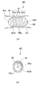
また、前記カプセル型医療装置1は、前記カプセル本体1Aの外周面に推力発生部として、体腔内のガスや体液等の流体が前後に連通可能な螺旋溝37aを形成した螺旋部37が設けられている。このことにより、前記カプセル型医療装置1は、前記カプセル本体1Aの回転に伴い、前記螺旋溝37aに体腔内のガスや体液等の流体が連通することで、回転力が推進力に変換されて、進退動可能になっている。また、螺旋突起部37bは、体腔内壁に接触しても粘膜を損傷することがないように滑らかに仕上げられており、この突起部と粘膜との接触摩擦力が更に大きな推進力となるように構成してある。
【0031】
尚、前記カプセル型医療装置1は、回転磁界の回転に伴い前記磁石36の回転平面と回転磁場の回転平面とが一致するように前記カプセル本体1Aが回転しながら進行方向(向き)を変更するようになっている。
【0032】
ここで、カプセル型医療装置1は、カプセル本体1Aの長手中心軸38上に重心が略一致していないと、カプセル本体1Aが偏心運動(ジグリング)をして無駄な動きを起こしてしまう。
【0033】
本実施の形態では、カプセル型医療装置1は、最も重い釦電池等のバッテリ27aを長手中心軸38上に配置すると共に、前記磁石36をカプセル本体1Aの長手中心軸38上に配置し、カプセル本体1Aの長手中心軸38上に重心を略一致させるように構成している。このことにより、カプセル型医療装置1は、カプセル本体1Aが偏芯運動(ジグリング)等の無駄な動きをすることなく、管腔管路内をスムーズに目的部位まで到達可能に構成される。
【0034】
次に、本実施の形態のカプセル型医療装置1による動作を以下に説明する。
図1に示すように、患者2の例えば胃51内部等の体腔管路内を長時間にわたり観察する必要がある場合、操作者は、カプセル型医療装置1を患者2に飲み込ませ、胃51内を通過させる状態にする。尚、このとき、操作者は、患者2に飲み込ませる直前に予め、カプセル型医療装置1のスイッチ27をオンし、バッテリ部26のバッテリ26aの電源電力が照明装置23、観察装置24、デジタル信号デジタル信号処理回路25,無線送受信回路22へ伝達されるようにする。と同時に、操作者は、磁気誘導装置5を起動(オン)し、この磁気誘導装置5の形成する回転磁界により体腔管路内においてカプセル型医療装置1が目的部位に到達するよう磁気的に制御する。
【0035】
上述したようにカプセル型医療装置1は、磁気誘導装置5の形成する回転磁界に磁石36が作用すると、この磁石36が受ける作用によりカプセル本体1Aが回転する。そして、カプセル型医療装置1は、螺旋部37の螺旋溝37aに連通する体腔内のガスや体液等の流体により、カプセル本体1Aの回転力が推進力に変換されて進退動する。更に、カプセル本体1Aは、体腔内壁と接触したとき、この体腔内壁の粘膜と螺旋突起部37bとの間の摩擦力が大きな推進力に変換されて進退動する。また、カプセル型医療装置1は、回転磁界の回転に伴い、磁石36の回転平面と回転磁場の回転平面とが一致するようにカプセル本体1Aが回転しながら進行方向(向き)を変更される。
【0036】
このとき、カプセル型医療装置1は、カプセル本体1Aが偏芯運動等の無駄な動きをすることなく、管腔管路内をスムーズに目的部位まで到達可能である。
【0037】
そして、カプセル型医療装置1は、口腔52から食道53を通過し、胃51内部へ到達する。このとき、食道53は、例えば長径が約16mm、短径が約14mmであるのでカプセル型医療装置1は、その外径が14mm以下の略円形断面にしておけば、容易に通過可能である。
【0038】
そして、胃51内部を観察する必要がある場合、操作者は、制御装置3の例えばキーボード12から観察開始のコマンドに対応するキー入力を行う。すると、このキー入力による制御信号は、制御装置3の体外アンテナ14を経て電波で放射されてカプセル型医療装置1側に送信される。
カプセル型医療装置1は、無線アンテナ21で受信した信号により、動作開始の信号を検出し、無線送受信回路22、照明装置23、観察装置24、デジタル信号処理回路25等が駆動する。
【0039】
照明装置23は、観察装置24の視野方向に照明光を出射し、照明された部分の視野範囲の光学像が観察装置24の撮像センサ32に結像されて光電変換されて撮像信号を出力する。この撮像信号は、デジタル信号処理回路25の映像信号処理回路34でデジタル映像信号に変換された後、圧縮処理回路35で圧縮処理されて無線送受信回路22で変調され、無線アンテナ21から電波で放射される。
【0040】
この電波は、制御装置3の体外アンテナ14で受信され、パソコン本体11内の受信回路で復調され、パソコン本体11内のA/Dコンバータでデジタル信号に変換され、メモリに格納されると共に、所定の速度で読み出されモニタ13に撮像センサ32で撮像された光学画像がカラー表示される。操作者は、この画像を観察することにより、患者2の胃51内部を観察することができる。この観察画像を見ながら、体外のジョイスティックなどの操作手段を用いて、胃内全域の観察が行えるように外部磁力のかけ方を容易にコントロールできる。尚、この光学画像は図示しない画像記録装置に記録することもできる。
【0041】
胃51内の観察が終了した後、カプセル型医療装置1は、上述したように磁気誘導装置5で形成される回転磁界により、磁気的に誘導されて、胃51から十二指腸54、図示しない小腸、大腸を経由し、肛門から取り出される。この間、カプセル型医療装置1は、消化管全体の内部を観察することが可能である。
【0042】
この結果、本実施の形態のカプセル型医療装置1は、カプセル本体1Aが偏芯運動(ジグリング)等の無駄な動きをすることなく、管腔管路内をスムーズに目的部位まで到達することができる。
また、本実施の形態のカプセル型医療装置1は、無駄な動きがない分、磁気誘導効率が良くなり、カプセル本体内、体外両方又は一方の磁石を小型化できるという大きな効果がある。
【0043】
また、カプセル型医療装置は、図4に示すように治療又は処置が可能なようにに薬剤散布用に構成しても良い。即ち、前記カプセル型医療装置60は、カプセル本体60A内の薬剤収納部61に収納した薬剤を散布可能なように先端側に設けた薬剤散布用開口部61aを設けて構成されている。
【0044】
更に、前記カプセル型医療装置60は、体液採取用に構成されている。即ち、前記カプセル型医療装置60は、カプセル本体60A内の体液収納部62に体液を採取可能なように体液注入用開口部62aを後端側に設けて構成されている。尚、これら開口部61a,62aの開閉は、上記第1の実施の形態で説明した制御装置3からの通信制御により行われる。このことにより、前記カプセル型医療装置60は、目的部位にて薬剤収納部61の薬剤を薬剤散布用開口部61aから放出して散布可能であると共に、体液収納部62に体液注入用開口部62aから体液を採取可能である。
【0045】
また、薬剤収納部61は、薬剤の他に出血を止める止血剤、出血部位を外部から判別可能にするための生体に安全な磁性流体や蛍光剤などを収納して目的部位で散布するようにしても当然良い。
また、前記カプセル型医療装置60は、前記体液注入用開口部62aから取り込んだ体液に薬剤収納部61の薬剤を混ぜて薬剤散布用開口部61aから放出して散布可能に構成しても良い。尚、カプセル型医療装置60は、図示しないが上記第1の実施の形態と同様にカプセル本体の長手中心軸38上に重心を略一致させる構成としている。
【0046】
また、カプセル型医療装置は、図5に示すように外装部材として螺旋溝を形成した弾性ゴムカバーを前記カプセル本体に着脱自在に装着可能に構成しても良い。即ち、図5(a),(b)に示すようにカプセル型医療装置70は、螺旋溝71aを形成した弾性ゴムカバー71をカプセル本体70Aに着脱自在に装着可能に構成されている。このことにより、前記カプセル型医療装置70は、前記弾性ゴムカバー71の螺旋溝71aを介してガスや体液等の流体が先端側及び後端側に連通するようになっている。
【0047】
また、前記カプセル型医療装置70は、治療又は処置が可能なように処置具収納部72を前記カプセル本体70Aに有し、この先端側に処置具用開口部72aを形成している。この処置具開口部72aは、例えば、胃液で消化されるゼラチンや腸液で消化される脂肪酸膜等から形成される溶解膜を埋設して塞いでいる。そして、前記カプセル型医療装置70は、目的部位付近に到達したら前記処置具開口部72aが開口するようになっている。
【0048】
そして、前記処置具収納部72に収納される処置具73は、その先端側を前記処置具用開口部72aから突没自在で、体腔内管路の目的部位に対して治療又は処置が可能である。前記処置具73は、上記第1の実施の形態で説明した制御装置3からの通信制御により動作制御が行われる。尚、前記処置具73の具体的な動作制御は、パソコン本体11に接続される図示しないジョイスティックやマウスなどの操作手段で行うように構成しても良い。
【0049】
尚、図5(a)中、前記処置具73は、止血用薬剤を注入可能な注射針である。この場合、前記カプセル型医療装置70は、図示しない血液センサや前記観察装置24で出血部位を確認後、前記制御装置3からの通信制御により、カプセル本体70Aの内部に収納した止血剤注入注射針等の処置具73の動作を指示し、止血剤であるエタノールや粉末薬品を出血部位に散布して止血するようになっている。
【0050】
更に、また、前記カプセル型医療装置70は、検査が可能なように超音波部74を前記カプセル本体に有して構成されている。前記超音波部74は、図示しないが超音波を送受信する超音波探触子及びこの超音波探触子を制御駆動する超音波制御回路を有して構成されている。
【0051】
前記カプセル型医療装置70は、前記カプセル本体70Aの後端側外面に図示しない音響レンズ部が位置されるように超音波探触子を水密に配置しており、この後端側で例えば360°の超音波断層像を得られるように構成されている。
そして、前記カプセル型医療装置70は、得られた超音波断層像のデータを上記第1の実施の形態で説明した観察画像と同様に無線送受信回路22で変調され、無線アンテナ21から電波で放射される。これにより、前記カプセル型医療装置70は、小腸55等体腔内深部の深さ方向の異常の有無の診断が可能となっている。尚、前記カプセル型医療装置70は、前記観察装置24と両方を備える構成にすれば、体腔内表面と深部との両方の診断が一度に可能である。
【0052】
また、前記カプセル型医療装置70は、胃内,小腸から口側へ、又は大腸から肛門側へ検査後に引き抜くための軟性プラスティックなどで体腔粘膜を損傷しないように軟らかさと太さ及び強度を兼ね備えた紐75を前記カプセル本体70Aに取り付けて構成されている。この紐75は、カプセル本体70Aの回転推進に邪魔にならない程度に軟らかく形成されている。尚、この紐75は、基端側を結んで体外に固定して用いるようになっている。尚、カプセル型医療装置70は、図示しないが上記第1の実施の形態の形態と同様にカプセル本体70Aの長手中心軸38上に重心を略一致させる構成としている。
【0053】
また、カプセル型医療装置は、カプセル本体の進行方向の後方側に前記螺旋部37及び前記観察装置24を設けて構成しても良い。即ち、図6に示すようにカプセル型医療装置80は、カプセル本体80Aの進行方向の後方側に前記螺旋部37を着脱自在に設けると共に、前記観察装置24を前記照明装置23と共にカプセル本体80Aの進行方向の後方側に設けて構成される。
また、図7に示すようにカプセル型医療装置81は、前記磁石36を複数設け、カプセル本体1Aの長手中心軸38上に対称に配置して構成しても良い。
【0054】
また、カプセル型医療装置は、図8に示すようにカプセル本体の進行方向側に前記螺旋部37を着脱自在に設けると共に、前記観察装置24をカプセル本体の進行方向の後方側に設けて構成しても良い。
即ち、図8(a)に示すようにカプセル型医療装置83は、カプセル本体83Aの進行方向側に螺旋部37を着脱自在に設けると共に、前記観察装置24を前記照明装置23と共にカプセル本体83Aの進行方向の後方側に設けて構成されている。尚、符号27Bは、バッテリ部26のバッテリ26aから供給される電源電力をオンオフするスイッチである。
尚、図8(b)は、同図(a)の他の方向から見た断面図である。
図8(b)に示すようにカプセル型医療装置83は、前記磁石36をカプセル本体83Aの長手中心軸38と平行に設けている。カプセル型医療装置83は、前記磁石36の下部に前記デジタル信号処理回路25、前記無線送受信回路22を配置している。
【0055】
また、前記カプセル型医療装置83は、図9(a),(b)に示すように内視鏡84の処置具挿通用チャンネル85に挿通したカプセル回収具86により回収されるようになっている。
内視鏡84は、前記処置具挿通用チャンネル84aにカプセル回収具85を挿通可能である。尚、符号87は、内視鏡84の挿入部先端部84aに設けた観察装置である。この観察装置87は、対物光学系87a及びこの対物光学系87aの結像位置に設けた撮像部87bで構成されている。
前記カプセル回収具85は、可撓性で棒状に形成され、この先端側に前記カプセル型医療装置83を回収するための磁石88を内蔵している。また、前記カプセル回収具85は、前記カプセル型医療装置83が前記磁石88に捉えられた際に、前記カプセル本体83Aの螺旋部37が邪魔にならないように凹部89を形成している。
【0056】
また、図10に示すようにカプセル型医療装置90は、前記観察装置24を配置した部分と、前記磁石36及び前記螺旋部37を配置した部分との2つにカプセル本体90Aを分割可能に構成しても良い。このことにより、カプセル型医療装置90は、図10(a)に示す観察装置24の観察視野方向が後方側のものと、図10(b)に示す観察装置24の観察視野方向が後方斜視側のものと、図10(c)に示す観察装置24の観察視野方向が後方側視側のものと、用途に合わせて取り換えることが可能である。
【0057】
また、カプセル型医療装置は、図11に示すように前記螺旋部37を設けた部分を細長で可撓性の例えば、弾性ゴム等の可撓性軟性部で形成しても良い。
即ち、図11(a)に示すようにカプセル型医療装置100は、前記螺旋部37を設けた部分を細長で可撓性の可撓性軟性部101に形成すると共に、磁石36a、36bの2つを長手中心軸38に対して対称に配置して構成されている。尚、この場合、図11(b)に示すようにカプセル型医療装置100は、前記観察装置24の周囲にリング状に複数のLEDを配置して前記照明装置23を構成しても良い。
また、前記可撓性軟性部101を有するカプセル型医療装置100は、図12(a),(b)に示すように前記磁石36を一体的にリング状に形成して構成しても良い。
【0058】
また、図13に示すようにカプセル型医療装置110は、前記可撓性軟性部101に前記螺旋部37を設けるのでなく、進行方向の後方側に設けて構成しても良い。
この場合、カプセル型医療装置110は、図13(a)に示すように観察装置24の観察視野方向が後方側のものと、図13(b)に示す観察装置24の観察視野方向が後方斜視側のものと、図13(c)に示す観察装置24の観察視野方向が後方側視側のものと、用途に合わせて取り換えることが可能である。
【0059】
尚、図13(a)に示すカプセル型医療装置110は、前記螺旋部37がカプセル本体110Aの後方側のほぼ全周に亘って設けられている。また、図13(b)に示すカプセル型医療装置110は、後方斜視可能なように前記螺旋部37がカプセル本体110Aの後方側の斜め半分に亘って設けられている。また、図13(c)に示すカプセル型医療装置110は、後方側視可能なように前記螺旋部37がカプセル本体110Aの後方側の半分に亘って設けられている。
【0060】
また、カプセル型医療装置は、図14に示すように可撓性軟性部をカプセル本体に着脱自在に装着可能に構成しても良い。図14(a)に示すようにカプセル型医療装置120は、可撓性軟性部121をカプセル本体120Aに着脱自在に装着可能に構成されている。前記可撓性軟性部121は、図14(b)に示すように軟らかいので容易に屈曲可能である。
【0061】
尚、本実施の形態では、制御装置3と送受信する無線アンテナ21を有し、体腔管路内を通過させて前記制御装置3の制御により、検査、治療又は処置が可能なカプセル型医療装置に本発明を適用して構成しているが、本発明はこれに限定されず、無線アンテナ21を設けることなく、体腔管路内を通過させて体外から回収後に光学画像等の情報(データ)を取り出すカプセル型医療装置に本発明を適用して構成しても構わない。
【0062】
(第2の実施の形態)
図15ないし図21は本発明の第2の実施の形態に係り、図15は本発明の第2の実施の形態のカプセル型医療装置を示す説明図、図16は図15のカプセル型医療装置の管腔内部での動作を示す説明図、図17は管腔臓器の最大径に対して、カプセル本体の硬質長と可撓性軟性部の軟質長との関係を示す説明図、図18は図15のカプセル型医療装置の管腔臓器内の屈曲部や細径部等での動作を示す説明図、図19は可撓性軟性部の外周面に針金状部材を接着固定して螺旋部を形成したカプセル型医療装置を示す外観図、図20は可撓性軟性部をボール状の磁石を内蔵して形成したボール状突起部を複数形成して構成したカプセル型医療装置を示す説明図、図21は図20のカプセル型医療装置の管腔内部での動作を示す説明図である。
【0063】
本第2の実施の形態は、可撓性軟性部をカプセル本体に着脱自在に装着可能に構成する。それ以外の構成は、上記第1の実施の形態とほぼ同様なので説明を省略し、同じ構成には同じ符号を付して説明する。
【0064】
即ち、図15に示すように本発明の第2の実施の形態の形態のカプセル型医療装置150は、可撓性軟性部151を更に細長く形成し、カプセル本体150Aに着脱自在に装着可能に構成されている。
【0065】
前記可撓性軟性部151は、長手中心軸38上に前記磁石36を内蔵し、基端側に前記カプセル本体150Aを装着可能な装着部151aが形成されている。そして、前記可撓性軟性部151は、前記カプセル本体150Aに装着されてカプセル型医療装置150を構成する。また、カプセル型医療装置150は、図示しないが上記第1の実施の形態の形態と同様にカプセル本体150Aの長手中心軸38上に重心を略一致させる構成としている。
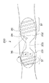
そして、カプセル型医療装置150は、図16に示すように管腔内部で前記可撓性軟性部151が進行方向をさぐりながら移動するようになっている。
【0066】
尚、前記カプセル型医療装置150は、図17に示すように大腸などの管腔臓器の最大径Lに対して、カプセル本体150Aの硬質長L1と前記可撓性軟性部151の軟質長L2との関係がL1<L<L1+L2となるように構成されても良い。
この場合、カプセル型医療装置150は、管腔臓器の最大径Lより長い、しかも硬質長が短いので、進行方向の向きが管腔内で変わらず、また、前記磁石36による回転力が推進力にそのまま変換されるので、回転力を推進力に効率良く変換でき、スムーズに管腔内を移動可能である。
【0067】
また、カプセル型医療装置150は、図18に示すように小腸や大腸などの管腔臓器内の屈曲部や細径部等で前記磁石36による回転をしながら、前記可撓性軟性部151で進行方向をこじあけるように入り込むことができ、それに続くカプセル本体150Aも容易に通過させることが可能である。
【0068】
また、図19に示すようにカプセル型医療装置160は、可撓性軟性部161の外周面に針金状部材162を接着固定して前記螺旋部37を形成しても良い。これにより、前記カプセル型医療装置160は、前記螺旋部37を前記可撓性軟性部161に設けるのが容易である。
【0069】
また、カプセル型医療装置170は、図20に示すように可撓性軟性部171をボール状の磁石172aを内蔵して形成したボール状突起部172を複数形成して構成しても良い。これにより、前記カプセル型医療装置170は、図21に示すように前記可撓性軟性部171が軟らかいので、回転しながら小腸や大腸等の管腔内臓器の屈曲部の奥まで入っていくことが可能である。
【0070】
(第3の実施の形態)
図22及び図23は本発明の第3の実施の形態に係り、図22は本発明の第3の実施の形態のカプセル型医療装置を示す説明図、図23は図22のカプセル型医療装置の変形例を示す説明図である。
【0071】
本第3の実施の形態は、カプセル本体を先端側硬質部と後端側硬質部との2つ設け、これら2つの硬質部を例えば、図示したような外形が滑らかに変化するウレタン、シリコンゴムなどの軟らかい弾性材で覆った紐状部材で接続して構成する。それ以外の構成は、上記第1の実施の形態とほぼ同様なので説明を省略し、同じ構成には同じ符号を付して説明する。
【0072】
即ち、図22に示すように本第3の実施の形態のカプセル型医療装置200は、カプセル本体200Aを先端側硬質部201と後端側硬質部202との2つ設け、これら2つの硬質部201,202を紐状部材203で接続して構成される。尚、カプセル型医療装置200は、図示しないが上記第1の実施の形態の形態と同様にカプセル本体200Aの長手中心軸38上に重心を略一致させる構成としている。
【0073】
また、前記カプセル型医療装置200は、前記先端側硬質部201と前記後端側硬質部202との両方に前記螺旋部37を設けている。また、前記観察装置24は、前記後端側硬質部202の先端側で前方斜視の観察視野方向を有するように構成されている。このことにより、前記カプセル型医療装置200は、管腔に密着しても、良好な観察視野を得られる。尚、前記カプセル型医療装置200は、先端側硬質部201に形成した突出部の一部も前記観察装置24の観察視野に入るため、この観察視野に入る部分に前記磁石36の配置(極性)が判る指標を設けている。
【0074】
また、図23に示すようにカプセル型医療装置210は、前記螺旋部37を設けた先端側硬質部201と後端側硬質部202との両方に前記磁石36と、前記観察装置24及び前記照明装置23とを設けて構成しても良い。この場合、前記カプセル型医療装置210は、どちらか一方の螺旋部37が、管腔内壁や体腔内流体と接触すれば、他の螺旋部37の接触の有無にかかわらず確実に推進力を生じさせることが可能となる。
【0075】
尚、本発明は、以上述べた実施形態のみに限定されるものではなく、発明の要旨を逸脱しない範囲で種々変形実施可能である。
【0076】
[付記]
(付記項1) 被検体内で検査、治療又は処置などの医療行為を行うカプセル型医療装置において、
被検体外の外部磁力に磁気的に作用される磁石と、
前記磁石による回転運動を推進力に変換するための推力発生部と、
を具備し、カプセル本体の長手中心軸上に本体重心を略一致させたことを特徴とするカプセル型医療装置。
【0077】
(付記項2) 前記カプセル本体の長手中心軸上に前記磁石の中心軸を略一致させたことを特徴とする付記項1に記載のカプセル型医療装置。
(付記項3) 前記カプセル本体の長手中心軸に対して略対称位置に前記磁石を複数配置したことを特徴とする付記項1に記載のカプセル型医療装置。
【0078】
(付記項4) 前記磁石による回転運動を推進力に変換するための推力発生部を前記カプセル本体に配置し、このカプセル本体の長手中心軸上に本体重心を略一致させる構成としたことを特徴とする付記項1に記載のカプセル型医療装置。
【0079】
(付記項5) 前記磁石による回転運動を推進力に変換するための推力発生部を前記カプセル本体に配置し、このカプセル本体の少なくとも一端に前方又は前方斜視の観察視野方向を有する観察手段を配置したことを特徴とする付記項1に記載のカプセル型医療装置。
【0080】
(付記項6) 少なくとも前記カプセル本体の一端に先端側がこの本体外径より細径にした可撓性挿入部を設け、この可撓性挿入部外面の少なくとも一部に前記磁石による回転運動を推進力に変換する推力発生部を配置したことを特徴とする付記項1に記載のカプセル型医療装置。
【0081】
(付記項7) 前記磁石がフェライト磁石であることを特徴とする付記項1に記載のカプセル型医療装置。
(付記項8) 前記磁石が希土類系磁石であることを特徴とする付記項1に記載のカプセル型医療装置。
(付記項9) 前記磁石がプラチナ磁石であることを特徴とする付記項1に記載のカプセル型医療装置。
【0082】
(付記項10) 前記磁石がアルニコ(AlNiCo)磁石であることを特徴とする付記項1に記載のカプセル型医療装置。
(付記項11) 前記磁石が鉄・クロム・コバルト磁石であることを特徴とする付記項1に記載のカプセル型医療装置。
(付記項12) 前記磁石が電磁コイルであることを特徴とする付記項1に記載のカプセル型医療装置。
【0083】
(付記項13) 前記磁石は、円盤状又はリング状に形成されることを特徴とする付記項2に記載のカプセル型医療装置。
(付記項14) 前記磁石は、棒状に形成されることを特徴とする付記項2又は3に記載のカプセル型医療装置。
【0084】
(付記項15) 前記カプセル本体の少なくとも一端に前方又は前方斜視の観察視野方向を有する観察手段を配置したことを特徴とする付記項1ないし3に記載のカプセル型医療装置。
(付記項16) 観察手段を前記カプセル本体の長手方向両端付近に複数設けたことを特徴とする付記項1ないし3に記載のカプセル型医療装置。
【0085】
(付記項17) 前記カプセル本体を複数の硬質部と、これら複数の硬質部を連結する細径軟質部とから構成し、これら複数の硬質部及び細径軟質部の両方に推力発生部を設けたことを特徴とする付記項1ないし3に記載のカプセル型医療装置。
【0086】
(付記項18) 前記カプセル本体を硬質部と、この硬質部に連結され、外径が徐々に細くなる軟質部とから構成し、前記カプセル本体の全長が被検体の大腸管腔の最大径より長くなるように構成したことを特徴とする付記項1ないし3に記載のカプセル型医療装置。
【0087】
(付記項19) 前記磁石の外周側極性及び磁気引力を生じて、前記カプセル本体を磁気引力で吸い寄せる磁石又は磁性体を先端付近に配置した紐状回収具を付帯したことを特徴とする付記項1ないし3に記載のカプセル型医療装置。
(付記項20) 前記推力発生部は、前記カプセル本体の外面に突出した螺旋状部であることを特徴とする付記項1ないし3に記載のカプセル型医療装置。
【0088】
(付記項21) 前記磁石は、前記カプセル本体の長手方向軸と直角方向に磁化方向を有することを特徴とする付記項1ないし3に記載のカプセル型医療装置。
【0089】
(付記項22) 前記希土類系磁石がサマリウムコバルト磁石であることを特徴とする付記項11に記載のカプセル型医療装置。
(付記項23) 前記希土類系磁石がネオジウム磁石であることを特徴とする付記項11に記載のカプセル型医療装置。
【0090】
(付記項24) 前記磁石を複数に分け、これら複数の磁石の合成磁力が強める向きに配置したことを特徴とする付記項15に記載のカプセル型医療装置。
(付記項25) 前記推力発生部を前記観察手段の観察の妨げにならない位置に配置したことを特徴とする付記項15又は16に記載のカプセル型医療装置。
【0091】
(付記項26) 被検体内で検査、治療又は処置などの医療行為を行うカプセル本体と、このカプセル本体の少なくとも一部に設け、被検体外の外部磁力に磁気的に作用される磁石と、を備えたカプセル型医療装置において、
前記磁石による回転運動を推進力に変換するための推力発生部を前記カプセル本体に配置し、このカプセル本体の長手中心軸上に本体重心を略一致させる構成としたことを特徴とするカプセル型医療装置。
【0092】
(付記項27) 前記カプセル本体の長手中心軸上に前記磁石の中心軸を略一致させたことを特徴とする付記項26に記載のカプセル型医療装置。
(付記項28) 前記カプセル本体の長手中心軸に対して略対称位置に前記磁石を複数配置したことを特徴とする付記項26に記載のカプセル型医療装置。
【0093】
(付記項29) 前記磁石は、円盤状又はリング状に形成されることを特徴とする付記項27に記載のカプセル型医療装置。
(付記項30) 前記磁石は、棒状に形成されることを特徴とする付記項27又は28に記載のカプセル型医療装置。
【0094】
(付記項31) 前記カプセル本体の少なくとも一端に前方又は前方斜視の観察視野方向を有する観察手段を配置したことを特徴とする付記項26ないし28に記載のカプセル型医療装置。
(付記項32) 観察手段を前記カプセル本体の長手方向両端付近に複数設けたことを特徴とする付記項26ないし28に記載のカプセル型医療装置。
【0095】
(付記項33) 前記カプセル本体を複数の硬質部と、これら複数の硬質部を連結する細径軟質部とから構成し、これら複数の硬質部及び細径軟質部の両方に推力発生部を設けたことを特徴とする付記項26ないし28に記載のカプセル型医療装置。
【0096】
(付記項34) 前記カプセル本体を硬質部と、この硬質部に連結され、外径が徐々に細くなる軟質部とから構成し、前記カプセル本体の全長が被検体の大腸管腔の最大径より長くなるように構成したことを特徴とする付記項26ないし28に記載のカプセル型医療装置。
【0097】
(付記項35) 前記磁石の外周側極性及び磁気引力を生じて、前記カプセル本体を磁気引力で吸い寄せる磁石又は磁性体を先端付近に配置した紐状回収具を付帯したことを特徴とする付記項26ないし28に記載のカプセル型医療装置。
【0098】
(付記項36) 前記推力発生部は、前記カプセル本体の外面に突出した螺旋状部であることを特徴とする付記項26ないし28に記載のカプセル型医療装置。
(付記項37) 前記磁石は、前記カプセル本体の長手方向軸と直角方向に磁化方向を有することを特徴とする付記項26ないし28に記載のカプセル型医療装置。
【0099】
(付記項38) 前記磁石を複数に分け、これら複数の磁石の合成磁力が強める向きに配置したことを特徴とする付記項34に記載のカプセル型医療装置。
(付記項39) 前記推進発生部を前記観察手段の観察の妨げにならない位置に配置したことを特徴とする付記項34又は35に記載のカプセル型医療装置。
【0100】
(付記項40) 被検体内で検査、治療又は処置などの医療行為を行うカプセル本体と、このカプセル本体の少なくとも一部に設け、被検体外の外部磁力に磁気的に作用される磁石と、を備えたカプセル型医療装置において、
前記磁石による回転運動を推進力に変換するための推力発生部を前記カプセル本体に配置し、このカプセル本体の少なくとも一端に前方又は前方斜視の観察視野方向を有する観察手段を配置したことを特徴とするカプセル型医療装置。
【0101】
(付記項41) 前記観察手段を前記カプセル本体の長手方向両端付近に複数設けたことを特徴とする付記項40に記載のカプセル型医療装置。
(付記項42) 前記複数の観察手段は、前記カプセル本体の長手方向両端の前方又は前方斜視の観察視野方向を有することを特徴とする付記項41に記載のカプセル型医療装置。
【0102】
(付記項43) 前記複数の観察手段のうち1つは、前記カプセル本体の略側方の観察視野方向を有することを特徴とする付記項41に記載のカプセル型医療装置。
(付記項44) 前記カプセル本体を複数の硬質部と、これら複数の硬質部を連結する細径軟質部とから構成し、これら複数の硬質部及び細径軟質部の両方に推力発生部を設けたことを特徴とする付記項41ないし43に記載のカプセル型医療装置。
【0103】
(付記項45) 被検体内で検査、治療又は処置などの医療行為を行うカプセル本体と、このカプセル本体の少なくとも一部に設け、被検体外の外部磁力に磁気的に作用される磁石と、を備えたカプセル型医療装置において、
少なくとも前記カプセル本体の一端に先端側がこの本体外径より細径にした可撓性挿入部を設け、この可撓性挿入部外面の少なくとも一部に前記磁石の回転運動を推進力に変換する推力発生部を配置したことを特徴とするカプセル型医療装置。
【0104】
(付記項46) 前記可撓性挿入部は、前記カプセル本体と着脱可能であることを特徴とする付記項45に記載のカプセル型医療装置。
(付記項47) 前記可撓性挿入部は、軟性ゴム又は合成樹脂であり、長手方向には縮まないが、外周方向に屈曲可能であることを特徴とする付記項46に記載のカプセル型医療装置。
【0105】
(付記項48) 前記磁石を前記可撓性挿入部内に配置したことを特徴とする付記項45ないし47に記載のカプセル型医療装置。
(付記項49) 前記可撓性挿入部の他端付近に、観察・測定などの検査、治療又は処置の少なくとも1つの医療行為を行う手段を具備したことを特徴とする付記項45ないし48に記載のカプセル型医療装置。
【0106】
【発明の効果】
以上説明したように本発明によれば、偏芯運動等の無駄な動きをすることなく、管腔管路内をスムーズに目的部位まで到達可能なカプセル型医療装置を実現できる。更に本発明によれば、無駄な動きを減らした分、磁気誘導効率が良くなるので、カプセル本体内の磁石、外部装置の磁石の両方又は一方の小型化が可能なカプセル型医療装置を実現できる。
【図面の簡単な説明】
【図1】本発明の第1の実施の形態を備えた医療システムを示す全体構成図
【図2】第1の実施の形態のカプセル型医療装置を示す回路ブロック図
【図3】図2のカプセル型医療装置の構成を示す構成図
【図4】薬剤散布用のカプセル型医療装置を示す構成図
【図5】処置具収納部及び超音波部を有するカプセル型医療装置を示す説明図
【図6】進行方向の後方側に螺旋部を着脱自在に設けると共に、観察装置を進行方向の後方側に設けて構成したカプセル型医療装置を示す断面図
【図7】磁石を複数設け、カプセル本体の長手中心軸上に対称に配置して構成したカプセル型医療装置を示す断面図
【図8】進行方向側に螺旋部を着脱自在に設けると共に、観察装置を進行方向の後方側に設けて構成したカプセル型医療装置を示す断面図
【図9】内視鏡の処置具挿通用チャンネルに挿通したカプセル回収具により回収されるカプセル型医療装置を示す説明図
【図10】観察装置を配置した部分と、磁石及び螺旋部を配置した部分との2つにカプセル本体を分割可能に構成したカプセル型医療装置を示す説明図
【図11】螺旋部を設けた部分を可撓性軟性部で形成したカプセル型医療装置を示す説明図
【図12】他の可撓性軟性部を有するカプセル型医療装置を示す説明図
【図13】可撓性軟性部に螺旋部を設けるのでなく、進行方向の後方側に設けて構成したカプセル型医療装置を示す説明図
【図14】可撓性軟性部をカプセル本体に着脱自在に装着可能に構成したカプセル型医療装置を示す説明図
【図15】本発明の第2の実施の形態のカプセル型医療装置を示す説明図
【図16】図15のカプセル型医療装置の管腔内部での動作を示す説明図
【図17】管腔臓器の最大径に対して、カプセル本体の硬質長と可撓性軟性部の軟質長との関係を示す説明図
【図18】図15のカプセル型医療装置の管腔臓器内の屈曲部や細径部等での動作を示す説明図
【図19】可撓性軟性部の外周面に針金状部材を接着固定して螺旋部を形成したカプセル型医療装置を示す外観図
【図20】可撓性軟性部をボール状の磁石を内蔵して形成したボール状突起部を複数形成して構成したカプセル型医療装置を示す説明図
【図21】図20のカプセル型医療装置の管腔内部での動作を示す説明図
【図22】本発明の第3の実施の形態のカプセル型医療装置を示す説明図
【図23】図22のカプセル型医療装置の変形例を示す説明図
【符号の説明】
1 …カプセル型医療装置
1A …カプセル本体
3 …体外装置
4 …医療システム
5 …磁気誘導装置
21 …無線アンテナ
22 …無線送受信回路
23 …照明装置
24 …観察装置
25 …デジタル信号処理回路
26 …バッテリ部
36 …磁石
37 …螺旋部(推力発生部)
38 …長手中心軸[0001]
BACKGROUND OF THE INVENTION
The present invention relates to a capsule medical device that can be examined, treated, or treated by passing through a body cavity duct.
[0002]
[Prior art]
2. Description of the Related Art Conventionally, a capsule medical device is a swallowable medical device that can be swallowed by a subject such as a patient and allowed to pass through a body cavity duct to be examined, treated, or treated.
The capsule-type medical device is configured to be capable of performing the medical action, for example, a treatment unit such as a medication unit capable of spraying a medicine or a forceps, a treatment tool unit that performs an incision / coagulation treatment using ultrasonic waves or high frequency, and the like. The medical action is performed at a target site in the body cavity duct. However, the capsule medical device cannot reach the target site or simply passes through it unless it is guided through the body cavity duct.
[0003]
In order to cope with this, for example, Japanese Patent No. 3017770 proposes a capsule medical device provided with a magnet that is magnetically acted on by an external magnetic force outside the subject.
The capsule-type medical device described in the above Japanese Patent No. 3017770 operates uniaxially in a vertical direction with respect to a magnet provided on the outer peripheral side of the capsule body by a uniform magnetic field which is an external magnetic force, and does not rotate. It is configured to be guided and propelled in the body cavity.
[0004]
On the other hand, the capsule medical device described in Japanese Patent Laid-Open No. 2001-179700 (P2001-179700A) is perpendicular to the magnet provided inside the capsule body by a rotating magnetic field that is an external magnetic force. In addition, there has been proposed one that obtains a propulsive force by acting in a triaxial manner in the horizontal direction and rotating freely.
The capsule medical device described in the above Japanese Patent Laid-Open No. 2001-179700 (P2001-179700A) has a capsule body with a thrust generating unit that obtains a propulsive force by rotating.
[0005]
[Problems to be solved by the invention]
However, in the capsule medical device described in Japanese Patent Laid-Open No. 2001-179700 (P2001-179700A), the internal structure of the capsule body is not considered when the capsule body is rotated.
In general, if the center of gravity of the object does not substantially coincide with the longitudinal center axis, an eccentric motion (Jigling) Will be a wasteful movement.
[0006]
For this reason, the capsule medical device described in the above Japanese Patent Laid-Open No. 2001-179700 (P2001-179700A) has an eccentric motion (Jigling) Or the like, and it may be difficult to smoothly reach the target site in the lumen.
[0007]
The present invention has been made in view of these circumstances, and provides a capsule medical device capable of smoothly reaching a target site in a lumen duct without making useless movement such as eccentric movement. For the purpose.
[0008]
[Means for Solving the Problems]
Of the present inventionA capsule medical device is a capsule medical device that performs medical actions such as examination, treatment, or treatment within a subject, and is provided on the capsule body and the capsule body, and is magnetically acted on by external magnetic force outside the subject. And a thrust generator provided in the capsule body for converting rotational movement by the magnet into a propulsive force, and the center of gravity of the body is substantially aligned with the longitudinal central axis of the capsule body. And
[0009]
DETAILED DESCRIPTION OF THE INVENTION
Embodiments of the present invention will be described below with reference to the drawings.
(First embodiment)
1 to 14 relate to a first embodiment of the present invention, FIG. 1 is an overall configuration diagram showing a medical system provided with the first embodiment of the present invention, and FIG. 2 is a first embodiment. FIG. 3 is a block diagram showing the configuration of the capsule medical device of FIG. 2, FIG. 3 (a) is a cross-sectional configuration diagram of the capsule medical device, and FIG. 3 (b). FIG. 3C is a structural view showing a capsule-type medical device for dispensing a medicine, FIG. 4A is an external view of a capsule medical device for spraying medicine, FIG. 4B is an external view of the distal end side of the capsule medical device in FIG. 5A, and FIG. 5 is a treatment instrument storage unit and an ultrasonic unit. FIG. 5A is an explanatory view showing a capsule-type medical device having an elastic rubber cover in which a spiral groove is formed. FIG. 21 (b) is a perspective view showing the elastic rubber cover of FIG. 21 (a), and FIG. 6 is a diagram showing a spiral part detachably provided on the rear side in the traveling direction. FIG. 6 is a cross-sectional view showing a capsule medical device in which an observation device is provided on the rear side in the traveling direction. FIG. 6A is a cross-sectional view of the capsule medical device, and FIG. FIG. 7 is a cross-sectional view showing a capsule medical device configured by providing a plurality of magnets and symmetrically arranging them on the longitudinal central axis of the capsule body. FIG. 7A is a cross-sectional view of the capsule medical device. 7B is a cross-sectional view of FIG. 7A, and FIG. 8 is a capsule type in which a spiral portion is detachably provided on the traveling direction side and an observation device is provided on the rear side in the traveling direction. It is sectional drawing which shows a medical device, Fig.8 (a) is sectional drawing of a capsule type medical device, figure (B) is a cross-sectional view seen from the other direction of FIG. (A), and FIG. 9 is an explanatory view showing a capsule medical device recovered by a capsule recovery tool inserted into a treatment instrument insertion channel of an endoscope. FIG. 9A is an explanatory view showing the distal end portion of the insertion portion of the endoscope, the capsule recovery tool, and the capsule medical device, FIG. 9B is a cross-sectional view of FIG. 9A, and FIG. FIG. 10A is an explanatory view showing a capsule medical device in which a capsule main body can be divided into a part where a device is arranged and a part where a magnet and a spiral part are arranged, and FIG. FIG. 10B is an explanatory diagram showing the capsule medical device whose direction of observation is the rear perspective side, and FIG. 10C is an observation of the observation device. FIG. 11 is an explanatory view showing a capsule medical device whose viewing direction is the rear view side. FIG. 11A is an explanatory view showing a capsule medical device in which a portion provided with a spiral portion is formed by a flexible soft portion, and FIG. 11A is an explanatory view showing a capsule medical device having a flexible soft portion, FIG. (B) is a cross-sectional view of FIG. (A), FIG. 12 is an explanatory view showing a capsule-type medical device having another flexible soft part, and FIG. FIG. 12 (b) is a cross-sectional view of FIG. 12 (a), and FIG. 13 is a view showing a capsule-type medical device formed and configured in the direction of travel. FIG. 13A is an explanatory diagram showing a capsule medical device provided on the rear side, and FIG. 13A is an explanatory diagram showing the capsule medical device in which the spiral portion is provided over substantially the entire circumference on the rear side of the capsule body. In FIG. 13 (b), the spiral portion is oblique to the rear side of the capsule body so that the rear perspective view is possible. FIG. 13C is an explanatory view showing a capsule type medical device provided over a minute, and FIG. 13C shows a capsule type in which a spiral portion is provided over the rear half of the capsule body so that it can be seen from the rear side. FIG. 14 is an explanatory view showing a medical device, FIG. 14 is an explanatory view showing a capsule-type medical device configured such that the flexible soft portion can be detachably attached to the capsule body, and FIG. 14 (a) shows the flexible soft portion. FIG. 14B is an external explanatory view showing the capsule medical device attached to the capsule body, and FIG. 14B is an external explanatory view showing the flexible soft part of FIG.
[0010]
As shown in FIG. 1, the capsule medical device 1 transmits and receives radio waves to and from a capsule control device (hereinafter referred to as a control device) 3 while passing through the body cavity of the
This medical system 4 is a screening test for the esophagus, duodenum, small intestine, and large intestine after pretreatment for the large intestine (intestinal irrigation) by drinking the capsule medical device 1 together with water in the same manner as a drug. is there. The medical system 4 captures an image at about 10 frames / second when the capsule medical device 1 passes through the esophagus and the like, and takes an image at about 2 frames / second when the passage through the small intestine is slow. Take a picture. The captured image is transferred to the
[0011]
The capsule medical device 1 is provided with a magnetic guiding device 5 to form a medical system 4. In addition, in FIG. 1, the magnetic guidance apparatus 5 is drawn typically.
The magnetic guiding device 5 is configured to form a rotating magnetic field for the capsule medical device 1 to magnetically act on a magnet described later provided on the
[0012]
The
[0013]
The
The generated control signal for controlling the magnetic induction device 5 is transmitted from the personal computer
[0014]
The magnetic induction device 5 forms a rotating magnetic field whose direction is controlled based on the transmitted control signal. Then, the capsule medical device 1 has a later-described thrust generating unit by rotating a capsule
[0015]
On the other hand, the generated control signal for controlling the capsule medical device 1 is modulated by a carrier wave having a predetermined frequency via a transmission circuit in the personal computer
[0016]
The capsule medical device 1 receives radio waves by a
Further, the
[0017]
Next, a detailed configuration of the capsule medical device according to the present embodiment will be described with reference to FIGS. 2 and 3. In the present embodiment, the capsule medical device is capable of only examination (observation).
The capsule medical device 1 includes a
[0018]
The wireless transmission /
[0019]
The
[0020]
The digital
[0021]
The
[0022]
The capsule medical device 1 includes a permanent magnet (hereinafter simply referred to as a magnet) 36 to be acted on the rotating magnetic field formed by the magnetic guidance device 5 as described above. The magnet used here is a permanent magnet such as a neodymium magnet, a samarium cobalt magnet, a ferrite magnet, an iron / chromium / cobalt magnet, a platinum magnet, or an AlNiCo magnet. Rare earth magnets such as neodymium magnets and samarium cobalt magnets have a strong magnetic force and are advantageous in that the magnets built into the capsule can be made smaller. On the other hand, ferrite magnets have the advantage of being inexpensive. Furthermore, platinum magnets have excellent corrosion resistance and are suitable for medical use.
[0023]
Further, the
[0024]
As shown in FIGS. 3A to 3C, the capsule medical device 1 includes, for example, a
[0025]
The
[0026]
In addition, the
[0027]
The
[0028]
In the capsule medical device 1, the above-described built-in object is reinforced and held by a cylindrical member such as a metal ring reinforcing member (not shown) and disposed on the main
[0029]
In the capsule medical device 1, the
[0030]
In addition, the capsule medical device 1 is provided with a
[0031]
The capsule medical device 1 changes the traveling direction (direction) while the
[0032]
Here, if the center of gravity of the capsule medical device 1 does not substantially coincide with the longitudinal
[0033]
In the present embodiment, the capsule medical device 1 has a battery 27a such as the heaviest button battery disposed on the longitudinal
[0034]
Next, operation | movement by the capsule type medical device 1 of this Embodiment is demonstrated below.
As shown in FIG. 1, when it is necessary to observe the inside of a body cavity such as the
[0035]
As described above, in the capsule medical device 1, when the
[0036]
At this time, the capsule medical device 1 can smoothly reach the target site in the lumen duct without causing the
[0037]
The capsule medical device 1 passes through the
[0038]
When it is necessary to observe the inside of the
The capsule medical device 1 detects an operation start signal based on a signal received by the
[0039]
The
[0040]
This radio wave is received by the
[0041]
After the observation in the
[0042]
As a result, in the capsule medical device 1 of the present embodiment, the
In addition, the capsule medical device 1 according to the present embodiment has a great effect that the magnetic induction efficiency is improved because there is no useless movement, and both the inside and outside of the capsule body or one of the magnets can be downsized.
[0043]
Further, the capsule medical device may be configured for drug distribution so that treatment or treatment is possible as shown in FIG. That is, the capsule
[0044]
Furthermore, the capsule
[0045]
In addition to the medicine, the
In addition, the capsule
[0046]
Further, the capsule medical device may be configured such that an elastic rubber cover in which a spiral groove is formed as an exterior member as shown in FIG. 5 can be detachably attached to the capsule body. That is, as shown in FIGS. 5A and 5B, the capsule
[0047]
The capsule
[0048]
The
[0049]
In FIG. 5A, the
[0050]
Furthermore, the capsule
[0051]
In the capsule
Then, the capsule
[0052]
Further, the capsule
[0053]
Further, the capsule medical device may be configured by providing the
Further, as shown in FIG. 7, the capsule
[0054]
Further, as shown in FIG. 8, the capsule medical device is configured such that the
That is, as shown in FIG. 8A, in the capsule
FIG. 8B is a cross-sectional view seen from the other direction of FIG.
As shown in FIG. 8B, the capsule
[0055]
Further, the capsule
The
The
[0056]
Further, as shown in FIG. 10, the capsule
[0057]
In the capsule medical device, as shown in FIG. 11, the portion provided with the
That is, as shown in FIG. 11A, in the capsule
In addition, the capsule
[0058]
Further, as shown in FIG. 13, the capsule
In this case, in the capsule
[0059]
In the capsule
[0060]
In addition, the capsule medical device may be configured so that the flexible soft part can be detachably attached to the capsule body as shown in FIG. As shown in FIG. 14A, the capsule
[0061]
In the present embodiment, a capsule medical device that has a
[0062]
(Second Embodiment)
15 to 21 relate to a second embodiment of the present invention, FIG. 15 is an explanatory view showing a capsule-type medical device according to the second embodiment of the present invention, and FIG. 16 is a capsule-type medical device of FIG. FIG. 17 is an explanatory diagram showing the relationship between the hard length of the capsule body and the soft length of the flexible soft part with respect to the maximum diameter of the luminal organ, and FIG. FIG. 19 is an explanatory view showing the operation of the capsule medical device at the bent portion, the small diameter portion, etc. in the luminal organ, and FIG. 19 shows the spiral portion by bonding and fixing a wire-like member to the outer peripheral surface of the flexible flexible portion. FIG. 20 is an explanatory view showing a capsule medical device formed by forming a plurality of ball-shaped protrusions formed by incorporating a ball-shaped magnet into a flexible soft part. FIG. 21 is an explanatory view showing the operation inside the lumen of the capsule medical device of FIG.
[0063]
The second embodiment is configured such that the flexible soft part can be detachably attached to the capsule body. Since other configurations are substantially the same as those of the first embodiment, the description thereof will be omitted, and the same components will be described with the same reference numerals.
[0064]
That is, as shown in FIG. 15, the capsule
[0065]
The flexible
In the capsule
[0066]
As shown in FIG. 17, the capsule
In this case, since the capsule
[0067]
Further, as shown in FIG. 18, the capsule
[0068]
Further, as shown in FIG. 19, the capsule
[0069]
In addition, as shown in FIG. 20, the capsule
[0070]
(Third embodiment)
22 and FIG. 23 relate to the third embodiment of the present invention, FIG. 22 is an explanatory view showing a capsule medical device of the third embodiment of the present invention, and FIG. 23 is a capsule medical device of FIG. It is explanatory drawing which shows the modification of this.
[0071]
In the third embodiment, the capsule body is provided with two hard parts, a front end side hard part and a rear end side hard part, and these two hard parts are, for example, urethane or silicon rubber whose outer shape changes smoothly as shown in the figure. And connected by a string-like member covered with a soft elastic material. Since other configurations are substantially the same as those of the first embodiment, the description thereof will be omitted, and the same components will be described with the same reference numerals.
[0072]
That is, as shown in FIG. 22, the capsule
[0073]
Further, the capsule
[0074]
Further, as shown in FIG. 23, the capsule
[0075]
The present invention is not limited to the above-described embodiments, and various modifications can be made without departing from the spirit of the invention.
[0076]
[Appendix]
(Additional Item 1) In a capsule medical device that performs medical actions such as examination, treatment, or treatment in a subject,
A magnet that is magnetically acted upon by an external magnetic force outside the subject;
A thrust generating unit for converting rotational movement by the magnet into propulsive force;
A capsule medical device characterized in that the center of gravity of the main body substantially coincides with the longitudinal central axis of the capsule main body.
[0077]
(Additional Item 2) The capsule medical device according to Additional Item 1, wherein a central axis of the magnet is substantially aligned with a longitudinal central axis of the capsule body.
(Additional Item 3) The capsule medical device according to Additional Item 1, wherein a plurality of the magnets are disposed at substantially symmetrical positions with respect to the longitudinal central axis of the capsule body.
[0078]
(Additional Item 4) A thrust generating portion for converting rotational movement by the magnet into propulsive force is disposed in the capsule main body, and the center of gravity of the main body substantially coincides with the longitudinal central axis of the capsule main body. The capsule medical device according to Item 1, wherein
[0079]
(Additional Item 5) A thrust generating unit for converting the rotational movement by the magnet into a propulsive force is arranged in the capsule body, and an observation means having an observation field direction of a front or front perspective is arranged at least at one end of the capsule body. The capsule medical device according to Additional Item 1, wherein the capsule medical device is characterized in that:
[0080]
(Additional Item 6) At least one end of the capsule body is provided with a flexible insertion portion whose tip side is smaller than the outer diameter of the main body, and rotational movement by the magnet is promoted on at least a part of the outer surface of the flexible insertion portion. 2. The capsule medical device according to Additional Item 1, wherein a thrust generating unit that converts force is disposed.
[0081]
(Additional Item 7) The capsule medical device according to Additional Item 1, wherein the magnet is a ferrite magnet.
(Additional Item 8) The capsule medical device according to Additional Item 1, wherein the magnet is a rare earth magnet.
(Additional Item 9) The capsule medical device according to Additional Item 1, wherein the magnet is a platinum magnet.
[0082]
(Additional Item 10) The capsule medical device according to Additional Item 1, wherein the magnet is an AlNiCo magnet.
(Additional Item 11) The capsule medical device according to Additional Item 1, wherein the magnet is an iron / chromium / cobalt magnet.
(Additional Item 12) The capsule medical device according to Additional Item 1, wherein the magnet is an electromagnetic coil.
[0083]
(Additional Item 13) The capsule medical device according to
(Additional Item 14) The capsule medical device according to
[0084]
(Additional Item 15) The capsule medical device according to any one of Additional Items 1 to 3, wherein an observation unit having an observation field direction of front or front perspective is arranged at least at one end of the capsule body.
(Additional Item 16) The capsule medical device according to any one of Additional Items 1 to 3, wherein a plurality of observation means are provided near both ends in the longitudinal direction of the capsule body.
[0085]
(Additional Item 17) The capsule body is composed of a plurality of hard parts and a thin soft part connecting the hard parts, and a thrust generating part is provided in both the hard part and the soft soft part. Item 4. The capsule medical device according to items 1 to 3, wherein
[0086]
(Additional Item 18) The capsule body is composed of a hard part and a soft part that is connected to the hard part and has an outer diameter that gradually decreases, and the total length of the capsule body is larger than the maximum diameter of the large intestine lumen of the subject. The capsule medical device according to any one of items 1 to 3, wherein the capsule medical device is configured to be long.
[0087]
(Additional Item 19) Additional remarks characterized by attaching a string-like recovery tool in which a magnet or a magnetic body that generates the outer peripheral polarity and magnetic attractive force of the magnet and attracts the capsule main body by magnetic attractive force is arranged near the tip. Item 4. The capsule medical device according to Item 1 to 3.
(Additional Item 20) The capsule medical device according to any one of Additional Items 1 to 3, wherein the thrust generation unit is a spiral portion protruding from an outer surface of the capsule body.
[0088]
(Additional Item 21) The capsule medical device according to Additional Items 1 to 3, wherein the magnet has a magnetization direction perpendicular to a longitudinal axis of the capsule body.
[0089]
(Additional Item 22) The capsule medical device according to
(Additional Item 23) The capsule medical device according to
[0090]
(Additional Item 24) The capsule medical device according to Additional Item 15, wherein the magnet is divided into a plurality of parts and arranged in a direction in which a combined magnetic force of the plurality of magnets is increased.
(Additional Item 25)PowerItem 17. The capsule medical device according to Item 15 or 16, wherein the generator is disposed at a position that does not interfere with observation of the observation means.
[0091]
(Additional Item 26) A capsule body that performs medical actions such as examination, treatment, or treatment in a subject, a magnet that is provided on at least a part of the capsule body, and that is magnetically acted on by external magnetic force outside the subject; In a capsule medical device comprising:
A capsule type medical device characterized in that a thrust generating unit for converting rotational movement by the magnet into propulsive force is arranged in the capsule body, and the center of gravity of the body is substantially coincided with the longitudinal central axis of the capsule body. apparatus.
[0092]
(Additional Item 27) The capsule medical device according to
(Additional Item 28) The capsule medical device according to
[0093]
(Additional Item 29) The capsule medical device according to
(Additional Item 30) The capsule medical device according to
[0094]
(Additional Item 31) The capsule medical device according to any one of
(Additional Item 32) The capsule medical device according to
[0095]
(Additional Item 33) The capsule body is composed of a plurality of hard portions and a thin soft portion connecting the hard portions, and a thrust generating portion is provided in both of the hard portions and the thin soft portion. Item 29. The capsule medical device according to any one of
[0096]
(Additional Item 34) The capsule body is composed of a hard part and a soft part that is connected to the hard part and has an outer diameter that gradually decreases, and the total length of the capsule body is larger than the maximum diameter of the large intestine lumen of the subject. 29. The capsule medical device according to any one of
[0097]
(Additional Item 35) Additional remarks characterized by attaching a string-like recovery tool in which a magnet or a magnetic body that generates the outer peripheral polarity and magnetic attractive force of the magnet and attracts the capsule main body by magnetic attractive force is arranged near the tip. Item 29. The capsule medical device according to
[0098]
(Additional Item 36) The capsule medical device according to
(Additional Item 37) The capsule medical device according to
[0099]
(Additional Item 38) The capsule medical device according to
(Additional Item 39) The capsule medical device according to
[0100]
(Additional Item 40) A capsule body that performs a medical act such as examination, treatment, or treatment in a subject, a magnet that is provided in at least a part of the capsule body, and that is magnetically acted on by an external magnetic force outside the subject; In a capsule medical device comprising:
A thrust generating unit for converting rotational movement by the magnet into propulsive force is disposed in the capsule body, and observation means having an observation field direction of front or front perspective is disposed at least at one end of the capsule body. Capsule type medical device.
[0101]
(Additional Item 41) The capsule medical device according to Additional Item 40, wherein a plurality of the observation means are provided near both ends in the longitudinal direction of the capsule body.
(Additional Item 42) The capsule medical device according to
[0102]
(Additional Item 43) The capsule medical device according to
(Additional Item 44) The capsule body is composed of a plurality of hard portions and a thin soft portion connecting the hard portions, and a thrust generating portion is provided in both of the hard portions and the thin soft portion. Item 44. The capsule medical device according to
[0103]
(Additional Item 45) A capsule body that performs a medical act such as examination, treatment, or treatment in a subject, a magnet that is provided on at least a part of the capsule body, and that is magnetically acted on by external magnetic force outside the subject; In a capsule medical device comprising:
At least one end of the capsule body is provided with a flexible insertion portion whose distal end is smaller than the outer diameter of the main body, and at least a part of the outer surface of the flexible insertion portion is a thrust that converts the rotational motion of the magnet into a propulsive force A capsule-type medical device, characterized in that a generator is arranged.
[0104]
(Additional Item 46) The capsule medical device according to Additional Item 45, wherein the flexible insertion portion is detachable from the capsule body.
(Additional Item 47) The capsule-type medical device according to Additional Item 46, wherein the flexible insertion portion is made of soft rubber or synthetic resin and does not shrink in the longitudinal direction but is bendable in the outer peripheral direction. apparatus.
[0105]
(Additional Item 48) The capsule medical device according to Additional Items 45 to 47, wherein the magnet is disposed in the flexible insertion portion.
(Additional Item 49) In Additional Items 45 to 48, a means for performing at least one medical act of examination, treatment, or treatment such as observation and measurement is provided near the other end of the flexible insertion portion. The capsule medical device as described.
[0106]
【The invention's effect】
As described above, according to the present invention, it is possible to realize a capsule medical device that can smoothly reach a target site in a lumen duct without making useless movement such as eccentric motion. Furthermore, according to the present invention, since the magnetic induction efficiency is improved by reducing the useless movement, it is possible to realize a capsule medical device capable of reducing the size of either or both of the magnet in the capsule body and the magnet of the external device .
[Brief description of the drawings]
FIG. 1 is an overall configuration diagram showing a medical system provided with a first embodiment of the present invention.
FIG. 2 is a circuit block diagram showing the capsule medical device according to the first embodiment.
3 is a configuration diagram showing the configuration of the capsule medical device of FIG. 2;
FIG. 4 is a block diagram showing a capsule medical device for spraying medicine.
FIG. 5 is an explanatory view showing a capsule medical device having a treatment instrument storage unit and an ultrasonic unit.
FIG. 6 is a cross-sectional view showing a capsule medical device configured such that a spiral portion is detachably provided on the rear side in the advancing direction and an observation device is provided on the rear side in the advancing direction.
FIG. 7 is a cross-sectional view showing a capsule medical device provided with a plurality of magnets and arranged symmetrically on the longitudinal central axis of the capsule body.
FIG. 8 is a cross-sectional view showing a capsule medical device configured such that a spiral portion is detachably provided on the traveling direction side and an observation device is provided on the rear side in the traveling direction.
FIG. 9 is an explanatory view showing a capsule medical device that is recovered by a capsule recovery tool that is inserted into a treatment instrument insertion channel of an endoscope.
FIG. 10 is an explanatory view showing a capsule medical device configured to be able to divide a capsule body into two parts, a part where an observation device is arranged and a part where a magnet and a spiral part are arranged.
FIG. 11 is an explanatory view showing a capsule medical device in which a portion provided with a spiral portion is formed of a flexible soft portion.
FIG. 12 is an explanatory view showing a capsule medical device having another flexible soft part.
FIG. 13 is an explanatory view showing a capsule-type medical device configured not to provide a spiral portion in the flexible soft portion but to be provided on the rear side in the advancing direction.
FIG. 14 is an explanatory view showing a capsule type medical device configured such that a flexible soft part can be detachably attached to a capsule body.
FIG. 15 is an explanatory view showing a capsule medical device according to a second embodiment of the present invention.
16 is an explanatory view showing the operation of the capsule medical device in FIG. 15 inside the lumen.
FIG. 17 is an explanatory diagram showing the relationship between the hard length of the capsule body and the soft length of the flexible soft part with respect to the maximum diameter of the luminal organ.
18 is an explanatory diagram showing the operation of the capsule medical device of FIG. 15 at a bent portion or a small diameter portion in a luminal organ.
FIG. 19 is an external view showing a capsule medical device in which a spiral member is formed by bonding and fixing a wire-like member to the outer peripheral surface of a flexible flexible part.
FIG. 20 is an explanatory view showing a capsule-type medical device configured by forming a plurality of ball-shaped protrusions in which a flexible soft part is formed by incorporating a ball-shaped magnet.
FIG. 21 is an explanatory view showing the operation inside the lumen of the capsule medical device of FIG.
FIG. 22 is an explanatory view showing a capsule medical device according to a third embodiment of the present invention.
FIG. 23 is an explanatory view showing a modification of the capsule medical device of FIG.
[Explanation of symbols]
1 ... Capsule type medical device
1A ... capsule body
3 ... extracorporeal device
4 ... Medical system
5 ... Magnetic induction device
21 ... Wireless antenna
22 ... Wireless transmission / reception circuit
23 ... Lighting device
24 ... Observation device
25 ... Digital signal processing circuit
26 ... Battery part
36 ... Magnet
37 ... Spiral part (thrust generating part)
38 ... Longitudinal central axis
Claims (7)
カプセル本体と、
前記カプセル本体に設けられ、被検体外の外部磁力に磁気的に作用される磁石と、
前記カプセル本体に設けられ、前記磁石による回転運動を推進力に変換する推力発生部と、
を具備し、
前記カプセル本体の長手中心軸上に本体重心を略一致させたことを特徴とするカプセル型医療装置。In a capsule medical device that performs medical actions such as examination, treatment or treatment within a subject,
A capsule body;
A magnet that is provided in the capsule body and is magnetically acted on by an external magnetic force outside the subject;
Provided in the capsule body, and thrust generating unit that converts the driving force of the rotational movement by the magnet,
Comprising
A capsule medical apparatus is characterized in that substantially matched the body center of gravity on the longitudinal central axis of the capsule body.
前記観察装置を有する第2のカプセル本体と、 A second capsule body having the observation device;
を備え、With
前記第1のカプセル本体と前記第2のカプセル本体とは、分割可能に構成されることを特徴とする請求項3に記載のカプセル型医療装置。 The capsule medical device according to claim 3, wherein the first capsule body and the second capsule body are configured to be separable.
る請求項1から6のいずれか一つに記載のカプセル型医療装置。The capsule medical device according to any one of claims 1 to 6.
Priority Applications (5)
| Application Number | Priority Date | Filing Date | Title |
|---|---|---|---|
| JP2002084387A JP3869291B2 (en) | 2002-03-25 | 2002-03-25 | Capsule medical device |
| US10/395,745 US7578788B2 (en) | 2002-03-25 | 2003-03-24 | Capsule-type medical device |
| US11/702,871 US20070173691A1 (en) | 2002-03-25 | 2007-02-06 | Capsule-type medical device |
| US11/702,873 US20070161862A1 (en) | 2002-03-25 | 2007-02-06 | Capsule-type medical device |
| US13/886,705 US20130245398A1 (en) | 2002-03-25 | 2013-05-03 | Capsule-type medical device |
Applications Claiming Priority (1)
| Application Number | Priority Date | Filing Date | Title |
|---|---|---|---|
| JP2002084387A JP3869291B2 (en) | 2002-03-25 | 2002-03-25 | Capsule medical device |
Related Child Applications (1)
| Application Number | Title | Priority Date | Filing Date |
|---|---|---|---|
| JP2005111330A Division JP4129269B2 (en) | 2005-04-07 | 2005-04-07 | Capsule medical device |
Publications (3)
| Publication Number | Publication Date |
|---|---|
| JP2003275170A JP2003275170A (en) | 2003-09-30 |
| JP2003275170A5 JP2003275170A5 (en) | 2005-08-25 |
| JP3869291B2 true JP3869291B2 (en) | 2007-01-17 |
Family
ID=28035825
Family Applications (1)
| Application Number | Title | Priority Date | Filing Date |
|---|---|---|---|
| JP2002084387A Expired - Fee Related JP3869291B2 (en) | 2002-03-25 | 2002-03-25 | Capsule medical device |
Country Status (2)
| Country | Link |
|---|---|
| US (4) | US7578788B2 (en) |
| JP (1) | JP3869291B2 (en) |
Families Citing this family (300)
| Publication number | Priority date | Publication date | Assignee | Title |
|---|---|---|---|---|
| US7553276B2 (en) * | 2001-01-16 | 2009-06-30 | Given Imaging Ltd. | Method and device for imaging body lumens |
| US9113846B2 (en) * | 2001-07-26 | 2015-08-25 | Given Imaging Ltd. | In-vivo imaging device providing data compression |
| US20050187433A1 (en) * | 2001-07-26 | 2005-08-25 | Given Imaging Ltd. | In-vivo imaging device providing constant bit rate transmission |
| US6896653B1 (en) * | 2002-03-07 | 2005-05-24 | Science For Medical Advocates, Inc. | Personal pelvic viewer |
| US7485093B2 (en) * | 2002-04-25 | 2009-02-03 | Given Imaging Ltd. | Device and method for in-vivo sensing |
| AU2003274635A1 (en) | 2002-10-15 | 2004-05-04 | Given Imaging Ltd. | Device, system and method for transfer of signals to a moving device |
| JP4503930B2 (en) * | 2003-01-30 | 2010-07-14 | オリンパス株式会社 | Medical equipment |
| IL155175A (en) * | 2003-03-31 | 2012-01-31 | Given Imaging Ltd | Diagnostic device using data compression |
| JP4422679B2 (en) * | 2003-04-25 | 2010-02-24 | オリンパス株式会社 | Capsule endoscope and capsule endoscope system |
| JP4451217B2 (en) * | 2004-06-01 | 2010-04-14 | オリンパス株式会社 | Capsule type communication system, capsule type medical device and biological information receiving device |
| IL162740A (en) * | 2003-06-26 | 2010-06-16 | Given Imaging Ltd | Device, method and system for reduced transmission imaging |
| US7960935B2 (en) | 2003-07-08 | 2011-06-14 | The Board Of Regents Of The University Of Nebraska | Robotic devices with agent delivery components and related methods |
| US20050038318A1 (en) * | 2003-08-13 | 2005-02-17 | Benad Goldwasser | Gastrointestinal tool over guidewire |
| US7833176B2 (en) * | 2003-08-13 | 2010-11-16 | G. I. View Ltd. | Pressure-propelled system for body lumen |
| US20050036059A1 (en) * | 2003-08-13 | 2005-02-17 | Benad Goldwasser | Ingestible imaging system |
| US20050038319A1 (en) * | 2003-08-13 | 2005-02-17 | Benad Goldwasser | Gastrointestinal tool over guidewire |
| US7153259B2 (en) * | 2003-09-01 | 2006-12-26 | Olympus Corporation | Capsule type endoscope |
| JP3993546B2 (en) * | 2003-09-08 | 2007-10-17 | オリンパス株式会社 | In-subject introduction apparatus and wireless in-subject information acquisition system |
| DE10346678A1 (en) * | 2003-10-08 | 2005-05-12 | Siemens Ag | Endoscopy device comprising an endoscopy capsule or an endoscopy head with an image recording device and imaging method for such an endoscopy device |
| JP4515747B2 (en) | 2003-10-27 | 2010-08-04 | オリンパス株式会社 | Capsule medical device |
| JP4009581B2 (en) * | 2003-11-18 | 2007-11-14 | オリンパス株式会社 | Capsule medical system |
| US7087011B2 (en) * | 2003-12-30 | 2006-08-08 | Gi View Ltd. | Gastrointestinal system with traction member |
| US7625338B2 (en) * | 2003-12-31 | 2009-12-01 | Given Imaging, Ltd. | In-vivo sensing device with alterable fields of view |
| US7635345B2 (en) * | 2004-01-09 | 2009-12-22 | G. I. View Ltd. | Pressure-propelled system for body lumen |
| US7947013B2 (en) * | 2004-01-09 | 2011-05-24 | G.I. View Ltd. | Pressure-propelled system for body lumen |
| US7635346B2 (en) * | 2004-01-09 | 2009-12-22 | G. I. View Ltd. | Pressure-propelled system for body lumen |
| US8419678B2 (en) | 2004-01-09 | 2013-04-16 | G.I. View Ltd. | Pressure-propelled system for body lumen |
| JP4578817B2 (en) * | 2004-02-06 | 2010-11-10 | オリンパス株式会社 | Surgical lesion identification system |
| US7751866B2 (en) * | 2004-03-08 | 2010-07-06 | Olympus Corporation | Detecting system of position and posture of capsule medical device |
| DE102004012245A1 (en) * | 2004-03-12 | 2005-09-29 | Siemens Ag | Probe mechanism e.g. catheter, for e.g. pH regulation, has magnetic component giving rise to dipole movement that is perpendicular to direction of extension of robot system, where outer side of mechanism is in spiral form |
| JP4624714B2 (en) * | 2004-05-10 | 2011-02-02 | オリンパス株式会社 | Endoscope |
| DE102004023527A1 (en) * | 2004-05-13 | 2005-12-08 | Osypka, Peter, Dr.-Ing. | measuring device |
| US8496580B2 (en) | 2004-05-14 | 2013-07-30 | G.I. View Ltd. | Omnidirectional and forward-looking imaging device |
| JP4354485B2 (en) * | 2004-05-14 | 2009-10-28 | オリンパス株式会社 | Insertion device |
| JP4530717B2 (en) * | 2004-05-20 | 2010-08-25 | オリンパス株式会社 | Endoscope |
| WO2005113374A2 (en) | 2004-05-21 | 2005-12-01 | Given Imaging Ltd. | Device, system and method for in-vivo sampling |
| DE102004026617B4 (en) * | 2004-06-01 | 2006-06-14 | Siemens Ag | Device for clamping tissue |
| JP4820365B2 (en) * | 2004-06-30 | 2011-11-24 | ギブン イメージング リミテッド | In-vivo detection system apparatus and method for real-time display |
| JP4526320B2 (en) * | 2004-07-30 | 2010-08-18 | オリンパス株式会社 | Endoscope |
| JP4891535B2 (en) * | 2004-09-21 | 2012-03-07 | オリンパス株式会社 | Medical device guidance system |
| EP1824374A1 (en) * | 2004-11-26 | 2007-08-29 | Olympus Corporation | Medical system |
| JP4699013B2 (en) * | 2004-11-26 | 2011-06-08 | オリンパス株式会社 | Capsule type medical device body and capsule type medical system |
| JP4746308B2 (en) * | 2004-11-29 | 2011-08-10 | オリンパス株式会社 | Internal medical device and internal medical system |
| JP4575124B2 (en) * | 2004-11-29 | 2010-11-04 | オリンパス株式会社 | Image display device |
| US20080108868A1 (en) * | 2004-12-02 | 2008-05-08 | Christopher Paul Swain | Device, System and Method of In-Vivo Electro-Stimulation |
| EP2361545B1 (en) * | 2005-01-06 | 2014-03-12 | G.I. View Ltd. | Gastrointestinal tool over guiding element |
| US20060173241A1 (en) * | 2005-01-14 | 2006-08-03 | Pentax Corporation | Front end structure of endoscope |
| US7909756B2 (en) * | 2005-01-26 | 2011-03-22 | Karl Storz Imaging, Inc. | Illumination system for variable direction of view instruments |
| EP1850689A4 (en) * | 2005-02-10 | 2013-05-22 | G I View Ltd | Advancement techniques for gastrointestinal tool with guiding element |
| DE102005007576A1 (en) * | 2005-02-18 | 2006-08-24 | Siemens Ag | Wirelessly navigable by means of a magnetic system capsule for performing a medical procedure in a hollow organ of a patient |
| DE102005007628A1 (en) * | 2005-02-18 | 2006-08-31 | Siemens Ag | Wireless navigable capsule and method for performing a medical procedure in a hollow organ of a patient |
| US7530948B2 (en) | 2005-02-28 | 2009-05-12 | University Of Washington | Tethered capsule endoscope for Barrett's Esophagus screening |
| AU2005328846B2 (en) * | 2005-03-09 | 2009-11-26 | Olympus Corporation | Device to be introduced into subject and system to be introduced into subject |
| US20090012359A1 (en) * | 2005-03-28 | 2009-01-08 | Shinsuke Tanaka | Medical instrument insertion apparatus and medical instrument insertion apparatus system |
| JP2006305320A (en) * | 2005-03-28 | 2006-11-09 | Olympus Corp | Medical instrument insertion device and medical instrument insertion device system |
| US20060224040A1 (en) * | 2005-03-31 | 2006-10-05 | Given Imaging Ltd. | In vivo imaging device and method of manufacture thereof |
| US20090023994A1 (en) * | 2005-04-05 | 2009-01-22 | Yasuhito Kura | Endoscope Insertion Portion and Endoscope |
| JP4914574B2 (en) * | 2005-04-18 | 2012-04-11 | オリンパスメディカルシステムズ株式会社 | Endoscope shape detection device |
| JP4709579B2 (en) * | 2005-04-26 | 2011-06-22 | オリンパスメディカルシステムズ株式会社 | Capsule endoscope |
| US8836513B2 (en) | 2006-04-28 | 2014-09-16 | Proteus Digital Health, Inc. | Communication system incorporated in an ingestible product |
| US8912908B2 (en) | 2005-04-28 | 2014-12-16 | Proteus Digital Health, Inc. | Communication system with remote activation |
| US8802183B2 (en) | 2005-04-28 | 2014-08-12 | Proteus Digital Health, Inc. | Communication system with enhanced partial power source and method of manufacturing same |
| US8730031B2 (en) | 2005-04-28 | 2014-05-20 | Proteus Digital Health, Inc. | Communication system using an implantable device |
| US9198608B2 (en) | 2005-04-28 | 2015-12-01 | Proteus Digital Health, Inc. | Communication system incorporated in a container |
| EP2671507A3 (en) | 2005-04-28 | 2014-02-19 | Proteus Digital Health, Inc. | Pharma-informatics system |
| DE102005056560A1 (en) * | 2005-05-09 | 2006-12-07 | Thiel, Christian, Dr. | Taxable Optrone II |
| DE102005031374A1 (en) * | 2005-07-05 | 2007-01-11 | Siemens Ag | Capsule to be used for magnetic wireless diagnosis of gastrointestinal tract, comprises cover to be removed after use |
| DE102005032371A1 (en) * | 2005-07-08 | 2007-01-11 | Siemens Ag | endoscopy capsule |
| US8491464B2 (en) * | 2005-07-08 | 2013-07-23 | Olympus Corporation | In-vivo information acquiring apparatus, in-vivo information acquiring system, and in-vivo information acquiring method |
| DE102005032378A1 (en) * | 2005-07-08 | 2007-01-11 | Siemens Ag | Magnetic navigable endoscopy capsule with sensor for detecting a physiological size |
| US8430809B2 (en) * | 2005-08-01 | 2013-04-30 | G. I View Ltd. | Capsule for use in small intestine |
| US20090182197A1 (en) * | 2005-08-01 | 2009-07-16 | G.I. View Ltd. | Tools for use in small intestine |
| US9241614B2 (en) * | 2005-08-01 | 2016-01-26 | G.I. View Ltd. | Tools for use in esophagus |
| EP1920418A4 (en) | 2005-09-01 | 2010-12-29 | Proteus Biomedical Inc | Implantable zero-wire communications system |
| CN101282677B (en) * | 2005-10-05 | 2010-07-28 | 奥林巴斯医疗株式会社 | Capsule type medical device, its guidance system and guidance method and examinee insertion device |
| US7482593B2 (en) * | 2005-10-20 | 2009-01-27 | The Research Foundation Of State University Of New York | Method to determine the depth-of-interaction function for PET detectors |
| JP4914600B2 (en) * | 2005-11-10 | 2012-04-11 | オリンパスメディカルシステムズ株式会社 | In-vivo image acquisition device, reception device, and in-vivo information acquisition system |
| US20070113860A1 (en) * | 2005-11-22 | 2007-05-24 | Anderson Peter T | Tracking apparatus and a method of using |
| JP4402648B2 (en) * | 2005-12-16 | 2010-01-20 | オリンパス株式会社 | Intra-subject introduction device |
| JPWO2007077922A1 (en) | 2005-12-28 | 2009-06-11 | オリンパスメディカルシステムズ株式会社 | Intra-subject introduction system and intra-subject observation method |
| US7678043B2 (en) * | 2005-12-29 | 2010-03-16 | Given Imaging, Ltd. | Device, system and method for in-vivo sensing of a body lumen |
| DE102006019985A1 (en) * | 2006-04-26 | 2007-10-31 | Siemens Ag | Orthopedic measures executing device for endoscopic surgery treatment, has part of magnetic body executing periodic translative movement and introducing impact forces on tool e.g. nail, where body is designed as single-piece |
| JP2009544338A (en) | 2006-05-02 | 2009-12-17 | プロテウス バイオメディカル インコーポレイテッド | Treatment regimen customized to the patient |
| US9579088B2 (en) | 2007-02-20 | 2017-02-28 | Board Of Regents Of The University Of Nebraska | Methods, systems, and devices for surgical visualization and device manipulation |
| US8679096B2 (en) | 2007-06-21 | 2014-03-25 | Board Of Regents Of The University Of Nebraska | Multifunctional operational component for robotic devices |
| JP5466004B2 (en) | 2006-06-22 | 2014-04-09 | ボード オブ リージェンツ オブ ザ ユニバーシティ オブ ネブラスカ | Magnetically connectable robotic device and associated method |
| US8974440B2 (en) | 2007-08-15 | 2015-03-10 | Board Of Regents Of The University Of Nebraska | Modular and cooperative medical devices and related systems and methods |
| JP4827667B2 (en) | 2006-09-07 | 2011-11-30 | オリンパスメディカルシステムズ株式会社 | Capsule endoscope |
| ATE535057T1 (en) | 2006-10-17 | 2011-12-15 | Proteus Biomedical Inc | LOW VOLTAGE OSCILLATOR FOR MEDICAL FACILITIES |
| SG175681A1 (en) | 2006-10-25 | 2011-11-28 | Proteus Biomedical Inc | Controlled activation ingestible identifier |
| EP2069004A4 (en) | 2006-11-20 | 2014-07-09 | Proteus Digital Health Inc | Active signal processing personal health signal receivers |
| US8702591B2 (en) * | 2007-01-12 | 2014-04-22 | Olympus Medical Systems Corp. | Capsule medical apparatus |
| US20080161639A1 (en) * | 2006-12-28 | 2008-07-03 | Olympus Medical Systems Corporation | Capsule medical apparatus and body-cavity observation method |
| WO2008081601A1 (en) * | 2007-01-05 | 2008-07-10 | Olympus Medical Systems Corp. | Capsule type medical device |
| AU2008210291B2 (en) | 2007-02-01 | 2013-10-03 | Otsuka Pharmaceutical Co., Ltd. | Ingestible event marker systems |
| US20080188710A1 (en) * | 2007-02-02 | 2008-08-07 | Olympus Medical Systems Corporation | Capsule medical apparatus and body-cavity observation method |
| MY154556A (en) | 2007-02-14 | 2015-06-30 | Proteus Digital Health Inc | In-body power source having high surface area electrode |
| US7655004B2 (en) | 2007-02-15 | 2010-02-02 | Ethicon Endo-Surgery, Inc. | Electroporation ablation apparatus, system, and method |
| CN101622773B (en) * | 2007-02-26 | 2012-05-23 | 奥林巴斯医疗株式会社 | Magnetic actuator, magnetic actuator operation method, and encapsulated endoscope using the same |
| EP2063771A1 (en) | 2007-03-09 | 2009-06-03 | Proteus Biomedical, Inc. | In-body device having a deployable antenna |
| US8932221B2 (en) | 2007-03-09 | 2015-01-13 | Proteus Digital Health, Inc. | In-body device having a multi-directional transmitter |
| US8075572B2 (en) | 2007-04-26 | 2011-12-13 | Ethicon Endo-Surgery, Inc. | Surgical suturing apparatus |
| US8100922B2 (en) | 2007-04-27 | 2012-01-24 | Ethicon Endo-Surgery, Inc. | Curved needle suturing tool |
| JP5269348B2 (en) * | 2007-05-21 | 2013-08-21 | オリンパス株式会社 | Position detection system and method of operating the position detection system |
| US8540632B2 (en) | 2007-05-24 | 2013-09-24 | Proteus Digital Health, Inc. | Low profile antenna for in body device |
| TWI342199B (en) * | 2007-07-06 | 2011-05-21 | Univ Nat Taiwan | Endoscope and magnetic field control method thereof |
| JP5591696B2 (en) | 2007-07-12 | 2014-09-17 | ボード オブ リージェンツ オブ ザ ユニバーシティ オブ ネブラスカ | Biopsy elements, arm devices, and medical devices |
| US9339174B2 (en) * | 2007-07-18 | 2016-05-17 | Given Imaging Ltd | Device and method for viewing a body lumen |
| US20090036952A1 (en) * | 2007-07-30 | 2009-02-05 | National Yang-Ming University | Induction driven light module and use thereof |
| JP2010536435A (en) | 2007-08-15 | 2010-12-02 | ボード オブ リージェンツ オブ ザ ユニバーシティ オブ ネブラスカ | Medical inflation, attachment and delivery devices and associated methods |
| US20110130658A1 (en) * | 2007-08-16 | 2011-06-02 | Rdc Ltd. | Ultrasonic capsule |
| US8568410B2 (en) | 2007-08-31 | 2013-10-29 | Ethicon Endo-Surgery, Inc. | Electrical ablation surgical instruments |
| US8262655B2 (en) | 2007-11-21 | 2012-09-11 | Ethicon Endo-Surgery, Inc. | Bipolar forceps |
| US8579897B2 (en) | 2007-11-21 | 2013-11-12 | Ethicon Endo-Surgery, Inc. | Bipolar forceps |
| EP2192946B1 (en) | 2007-09-25 | 2022-09-14 | Otsuka Pharmaceutical Co., Ltd. | In-body device with virtual dipole signal amplification |
| CN101808567B (en) * | 2007-09-26 | 2012-09-05 | 奥林巴斯医疗株式会社 | Introduction-into-subject system |
| DE102007051861B4 (en) | 2007-10-30 | 2020-03-12 | Olympus Corporation | Method for guiding a capsule endoscope and endoscope system |
| US20090112059A1 (en) | 2007-10-31 | 2009-04-30 | Nobis Rudolph H | Apparatus and methods for closing a gastrotomy |
| US8480657B2 (en) | 2007-10-31 | 2013-07-09 | Ethicon Endo-Surgery, Inc. | Detachable distal overtube section and methods for forming a sealable opening in the wall of an organ |
| AU2008329620B2 (en) | 2007-11-27 | 2014-05-08 | Otsuka Pharmaceutical Co., Ltd. | Transbody communication systems employing communication channels |
| JP5100336B2 (en) * | 2007-11-29 | 2012-12-19 | オリンパスメディカルシステムズ株式会社 | Capsule medical device |
| US8405477B2 (en) * | 2008-02-22 | 2013-03-26 | University Of Exeter | Controllable magnetic systems |
| ES2636844T3 (en) | 2008-03-05 | 2017-10-09 | Proteus Biomedical, Inc. | Ingestible multimode communication systems and markers, and methods to use them |
| US8262680B2 (en) | 2008-03-10 | 2012-09-11 | Ethicon Endo-Surgery, Inc. | Anastomotic device |
| JP5121523B2 (en) | 2008-03-24 | 2013-01-16 | オリンパスメディカルシステムズ株式会社 | Position detection system |
| JP5314913B2 (en) * | 2008-04-03 | 2013-10-16 | オリンパスメディカルシステムズ株式会社 | Capsule medical system |
| US8679003B2 (en) | 2008-05-30 | 2014-03-25 | Ethicon Endo-Surgery, Inc. | Surgical device and endoscope including same |
| US8652150B2 (en) | 2008-05-30 | 2014-02-18 | Ethicon Endo-Surgery, Inc. | Multifunction surgical device |
| US8114072B2 (en) | 2008-05-30 | 2012-02-14 | Ethicon Endo-Surgery, Inc. | Electrical ablation device |
| US8070759B2 (en) | 2008-05-30 | 2011-12-06 | Ethicon Endo-Surgery, Inc. | Surgical fastening device |
| US8317806B2 (en) | 2008-05-30 | 2012-11-27 | Ethicon Endo-Surgery, Inc. | Endoscopic suturing tension controlling and indication devices |
| US8771260B2 (en) | 2008-05-30 | 2014-07-08 | Ethicon Endo-Surgery, Inc. | Actuating and articulating surgical device |
| US8906035B2 (en) * | 2008-06-04 | 2014-12-09 | Ethicon Endo-Surgery, Inc. | Endoscopic drop off bag |
| US8403926B2 (en) | 2008-06-05 | 2013-03-26 | Ethicon Endo-Surgery, Inc. | Manually articulating devices |
| JP2010012222A (en) * | 2008-06-06 | 2010-01-21 | Olympus Medical Systems Corp | Medical apparatus |
| US8361112B2 (en) | 2008-06-27 | 2013-01-29 | Ethicon Endo-Surgery, Inc. | Surgical suture arrangement |
| CA2730275C (en) | 2008-07-08 | 2019-05-21 | Proteus Biomedical, Inc. | Ingestible event marker data framework |
| US8241206B2 (en) * | 2008-07-08 | 2012-08-14 | Olympus Medical Systems Corp. | System for guiding capsule medical device |
| US8235888B2 (en) * | 2008-07-08 | 2012-08-07 | Olympus Medical Systems Corp. | System for guiding capsule medical device |
| US20100010306A1 (en) * | 2008-07-08 | 2010-01-14 | Olympus Medical Systems Corp. | System for guiding capsule medical device |
| US8888792B2 (en) | 2008-07-14 | 2014-11-18 | Ethicon Endo-Surgery, Inc. | Tissue apposition clip application devices and methods |
| US8262563B2 (en) | 2008-07-14 | 2012-09-11 | Ethicon Endo-Surgery, Inc. | Endoscopic translumenal articulatable steerable overtube |
| CN102131452B (en) * | 2008-07-30 | 2014-03-12 | G.I.视频有限公司 | System and method for enhanced maneuverability |
| US8540633B2 (en) | 2008-08-13 | 2013-09-24 | Proteus Digital Health, Inc. | Identifier circuits for generating unique identifiable indicators and techniques for producing same |
| US8211125B2 (en) | 2008-08-15 | 2012-07-03 | Ethicon Endo-Surgery, Inc. | Sterile appliance delivery device for endoscopic procedures |
| US8529563B2 (en) | 2008-08-25 | 2013-09-10 | Ethicon Endo-Surgery, Inc. | Electrical ablation devices |
| US8241204B2 (en) | 2008-08-29 | 2012-08-14 | Ethicon Endo-Surgery, Inc. | Articulating end cap |
| US8480689B2 (en) | 2008-09-02 | 2013-07-09 | Ethicon Endo-Surgery, Inc. | Suturing device |
| US8409200B2 (en) | 2008-09-03 | 2013-04-02 | Ethicon Endo-Surgery, Inc. | Surgical grasping device |
| US8114119B2 (en) | 2008-09-09 | 2012-02-14 | Ethicon Endo-Surgery, Inc. | Surgical grasping device |
| DE102008049198B4 (en) * | 2008-09-26 | 2017-03-02 | Siemens Healthcare Gmbh | Coil system, medical device and method for non-contact magnetic navigation of a magnetic body in a workspace |
| US8337394B2 (en) | 2008-10-01 | 2012-12-25 | Ethicon Endo-Surgery, Inc. | Overtube with expandable tip |
| CA2741206C (en) | 2008-11-03 | 2016-01-12 | G.I. View Ltd | Remote pressure sensing system and method thereof |
| AU2009313879B2 (en) | 2008-11-13 | 2011-10-20 | Proteus Digital Health, Inc. | Ingestible therapy activator system and method |
| US20110282144A1 (en) * | 2008-11-17 | 2011-11-17 | Mayo Foundation For Medical Education And Research | Diagnostic capsules, delivery/retrieval systems, kits and methods |
| US8157834B2 (en) | 2008-11-25 | 2012-04-17 | Ethicon Endo-Surgery, Inc. | Rotational coupling device for surgical instrument with flexible actuators |
| KR100906464B1 (en) | 2008-11-26 | 2009-07-08 | 주식회사 인트로메딕 | An endoscope and a method for operating it |
| US8172772B2 (en) | 2008-12-11 | 2012-05-08 | Ethicon Endo-Surgery, Inc. | Specimen retrieval device |
| US8055334B2 (en) | 2008-12-11 | 2011-11-08 | Proteus Biomedical, Inc. | Evaluation of gastrointestinal function using portable electroviscerography systems and methods of using the same |
| TWI503101B (en) | 2008-12-15 | 2015-10-11 | Proteus Digital Health Inc | Body-associated receiver and method |
| US9659423B2 (en) | 2008-12-15 | 2017-05-23 | Proteus Digital Health, Inc. | Personal authentication apparatus system and method |
| US9439566B2 (en) | 2008-12-15 | 2016-09-13 | Proteus Digital Health, Inc. | Re-wearable wireless device |
| CA2750158A1 (en) | 2009-01-06 | 2010-07-15 | Proteus Biomedical, Inc. | Ingestion-related biofeedback and personalized medical therapy method and system |
| KR20110104079A (en) | 2009-01-06 | 2011-09-21 | 프로테우스 바이오메디컬, 인코포레이티드 | Pharmaceutical dosages delivery system |
| US8828031B2 (en) | 2009-01-12 | 2014-09-09 | Ethicon Endo-Surgery, Inc. | Apparatus for forming an anastomosis |
| US8361066B2 (en) | 2009-01-12 | 2013-01-29 | Ethicon Endo-Surgery, Inc. | Electrical ablation devices |
| US8252057B2 (en) | 2009-01-30 | 2012-08-28 | Ethicon Endo-Surgery, Inc. | Surgical access device |
| US9226772B2 (en) | 2009-01-30 | 2016-01-05 | Ethicon Endo-Surgery, Inc. | Surgical device |
| DE102009009616A1 (en) | 2009-02-19 | 2010-08-26 | Siemens Aktiengesellschaft | Endoscopic capsule with device for promoting movement in the case of movement-inhibiting edge friction |
| DE102009013352B4 (en) | 2009-03-16 | 2011-02-03 | Siemens Aktiengesellschaft | Coil arrangements for guiding a magnetic object in a working space |
| GB2480965B (en) | 2009-03-25 | 2014-10-08 | Proteus Digital Health Inc | Probablistic pharmacokinetic and pharmacodynamic modeling |
| SG10201810784SA (en) | 2009-04-28 | 2018-12-28 | Proteus Digital Health Inc | Highly Reliable Ingestible Event Markers And Methods For Using The Same |
| EP2432458A4 (en) | 2009-05-12 | 2014-02-12 | Proteus Digital Health Inc | Ingestible event markers comprising an ingestible component |
| WO2010147175A1 (en) * | 2009-06-19 | 2010-12-23 | 国立大学法人岩手大学 | Detection device, and recovery method and monitoring system therefor |
| EP2467707A4 (en) | 2009-08-21 | 2014-12-17 | Proteus Digital Health Inc | Apparatus and method for measuring biochemical parameters |
| WO2011030632A1 (en) | 2009-09-08 | 2011-03-17 | オリンパスメディカルシステムズ株式会社 | Device for insertion into tube |
| FR2950042B1 (en) * | 2009-09-17 | 2012-01-13 | Commissariat Energie Atomique | METHOD FOR MANUFACTURING A MICROPARTICLE AND MICROPARTICLE THUS MANUFACTURED |
| US20110098704A1 (en) | 2009-10-28 | 2011-04-28 | Ethicon Endo-Surgery, Inc. | Electrical ablation devices |
| TWI517050B (en) | 2009-11-04 | 2016-01-11 | 普羅托斯數位健康公司 | System for supply chain management |
| US8608652B2 (en) | 2009-11-05 | 2013-12-17 | Ethicon Endo-Surgery, Inc. | Vaginal entry surgical devices, kit, system, and method |
| US20110215888A1 (en) * | 2009-11-12 | 2011-09-08 | University Of Utah | Wireless control of microrobots |
| US20110115891A1 (en) * | 2009-11-13 | 2011-05-19 | Ethicon Endo-Surgery, Inc. | Energy delivery apparatus, system, and method for deployable medical electronic devices |
| UA109424C2 (en) | 2009-12-02 | 2015-08-25 | PHARMACEUTICAL PRODUCT, PHARMACEUTICAL TABLE WITH ELECTRONIC MARKER AND METHOD OF MANUFACTURING PHARMACEUTICAL TABLETS | |
| US9179827B2 (en) * | 2009-12-15 | 2015-11-10 | Boston Scientific Scimed, Inc. | Systems and methods for determining the position and orientation of medical devices inserted into a patient |
| US8496574B2 (en) | 2009-12-17 | 2013-07-30 | Ethicon Endo-Surgery, Inc. | Selectively positionable camera for surgical guide tube assembly |
| JP2013514835A (en) | 2009-12-17 | 2013-05-02 | ボード オブ リージェンツ オブ ザ ユニバーシティ オブ ネブラスカ | Modular and collaborative medical devices and related systems and methods |
| US8353487B2 (en) | 2009-12-17 | 2013-01-15 | Ethicon Endo-Surgery, Inc. | User interface support devices for endoscopic surgical instruments |
| US8506564B2 (en) | 2009-12-18 | 2013-08-13 | Ethicon Endo-Surgery, Inc. | Surgical instrument comprising an electrode |
| US9028483B2 (en) | 2009-12-18 | 2015-05-12 | Ethicon Endo-Surgery, Inc. | Surgical instrument comprising an electrode |
| WO2011084704A2 (en) * | 2009-12-21 | 2011-07-14 | The Smart Pill Corporation | Tethering capsule system |
| EP2347699B1 (en) * | 2010-01-22 | 2018-11-07 | Novineon Healthcare Technology Partners Gmbh | Capsule type endoscope including magnetic drive |
| US9005198B2 (en) | 2010-01-29 | 2015-04-14 | Ethicon Endo-Surgery, Inc. | Surgical instrument comprising an electrode |
| MX2012008922A (en) | 2010-02-01 | 2012-10-05 | Proteus Digital Health Inc | Data gathering system. |
| CN102905672B (en) | 2010-04-07 | 2016-08-17 | 普罗秋斯数字健康公司 | Miniature ingestible device |
| DE102010003808A1 (en) * | 2010-04-09 | 2011-10-13 | Siemens Aktiengesellschaft | endoscope |
| TWI557672B (en) | 2010-05-19 | 2016-11-11 | 波提亞斯數位康健公司 | Computer system and computer-implemented method to track medication from manufacturer to a patient, apparatus and method for confirming delivery of medication to a patient, patient interface device |
| WO2013022423A1 (en) | 2010-08-06 | 2013-02-14 | Board Of Regents Of The University Of Nebraska | Methods and systems for handling or delivering materials for natural orifice surgery |
| DE102010039184A1 (en) * | 2010-08-11 | 2012-01-05 | Siemens Aktiengesellschaft | Medical endoscope head i.e. passive endoscope capsule for use during e.g. diagnosis of patient, has camera moved between two image recording positions in which images are recorded, respectively |
| EP2642983A4 (en) | 2010-11-22 | 2014-03-12 | Proteus Digital Health Inc | Ingestible device with pharmaceutical product |
| CN102048517B (en) * | 2011-01-05 | 2012-05-30 | 华南理工大学 | Screw-type active-thrust capsule-like robot |
| US10092291B2 (en) | 2011-01-25 | 2018-10-09 | Ethicon Endo-Surgery, Inc. | Surgical instrument with selectively rigidizable features |
| US9254169B2 (en) | 2011-02-28 | 2016-02-09 | Ethicon Endo-Surgery, Inc. | Electrical ablation devices and methods |
| US9233241B2 (en) | 2011-02-28 | 2016-01-12 | Ethicon Endo-Surgery, Inc. | Electrical ablation devices and methods |
| US9314620B2 (en) | 2011-02-28 | 2016-04-19 | Ethicon Endo-Surgery, Inc. | Electrical ablation devices and methods |
| US9439599B2 (en) | 2011-03-11 | 2016-09-13 | Proteus Digital Health, Inc. | Wearable personal body associated device with various physical configurations |
| US9049987B2 (en) | 2011-03-17 | 2015-06-09 | Ethicon Endo-Surgery, Inc. | Hand held surgical device for manipulating an internal magnet assembly within a patient |
| EP4275634A3 (en) | 2011-06-10 | 2024-01-10 | Board of Regents of the University of Nebraska | Surgical end effector |
| US9756874B2 (en) | 2011-07-11 | 2017-09-12 | Proteus Digital Health, Inc. | Masticable ingestible product and communication system therefor |
| JP6106169B2 (en) | 2011-07-11 | 2017-03-29 | ボード オブ リージェンツ オブ ザ ユニバーシティ オブ ネブラスカ | Surgical robot system |
| WO2015112603A1 (en) | 2014-01-21 | 2015-07-30 | Proteus Digital Health, Inc. | Masticable ingestible product and communication system therefor |
| CA2842952C (en) | 2011-07-21 | 2019-01-08 | Proteus Digital Health, Inc. | Mobile communication device, system, and method |
| JP5907685B2 (en) | 2011-08-31 | 2016-04-26 | オリンパス株式会社 | Capsule medical device |
| US9235683B2 (en) | 2011-11-09 | 2016-01-12 | Proteus Digital Health, Inc. | Apparatus, system, and method for managing adherence to a regimen |
| CA2860754C (en) | 2012-01-10 | 2020-12-29 | Shane Farritor | Methods, systems, and devices for surgical access and insertion |
| US8986199B2 (en) | 2012-02-17 | 2015-03-24 | Ethicon Endo-Surgery, Inc. | Apparatus and methods for cleaning the lens of an endoscope |
| JP5437540B1 (en) * | 2012-03-21 | 2014-03-12 | オリンパスメディカルシステムズ株式会社 | Endoscope and spiral rotating member attached to insertion part of this endoscope |
| US20130267788A1 (en) * | 2012-04-04 | 2013-10-10 | Ankon Technologies Co. Ltd. | System and Method for Orientation and Movement of Remote Objects |
| EP2844181B1 (en) | 2012-05-01 | 2021-03-10 | Board of Regents of the University of Nebraska | Single site robotic device and related systems |
| US9427255B2 (en) | 2012-05-14 | 2016-08-30 | Ethicon Endo-Surgery, Inc. | Apparatus for introducing a steerable camera assembly into a patient |
| EP3424651B1 (en) | 2012-06-22 | 2020-02-12 | Board of Regents of the University of Nebraska | Local control robotic surgical devices |
| TWI468140B (en) * | 2012-06-25 | 2015-01-11 | Gi Shih Lien | Magnetic-controlled system applicable for colonoscopy |
| US9078662B2 (en) | 2012-07-03 | 2015-07-14 | Ethicon Endo-Surgery, Inc. | Endoscopic cap electrode and method for using the same |
| KR20150038038A (en) | 2012-07-23 | 2015-04-08 | 프로테우스 디지털 헬스, 인코포레이티드 | Techniques for manufacturing ingestible event markers comprising an ingestible component |
| US9545290B2 (en) | 2012-07-30 | 2017-01-17 | Ethicon Endo-Surgery, Inc. | Needle probe guide |
| US10314649B2 (en) | 2012-08-02 | 2019-06-11 | Ethicon Endo-Surgery, Inc. | Flexible expandable electrode and method of intraluminal delivery of pulsed power |
| US9572623B2 (en) | 2012-08-02 | 2017-02-21 | Ethicon Endo-Surgery, Inc. | Reusable electrode and disposable sheath |
| US9770305B2 (en) | 2012-08-08 | 2017-09-26 | Board Of Regents Of The University Of Nebraska | Robotic surgical devices, systems, and related methods |
| WO2014025399A1 (en) | 2012-08-08 | 2014-02-13 | Board Of Regents Of The University Of Nebraska | Robotic surgical devices, systems, and related methods |
| US9277957B2 (en) | 2012-08-15 | 2016-03-08 | Ethicon Endo-Surgery, Inc. | Electrosurgical devices and methods |
| US10045713B2 (en) | 2012-08-16 | 2018-08-14 | Rock West Medical Devices, Llc | System and methods for triggering a radiofrequency transceiver in the human body |
| JP6129509B2 (en) * | 2012-10-04 | 2017-05-17 | 東芝メディカルシステムズ株式会社 | Ultrasonic medical apparatus and ultrasonic diagnostic imaging apparatus |
| MX340182B (en) | 2012-10-18 | 2016-06-28 | Proteus Digital Health Inc | Apparatus, system, and method to adaptively optimize power dissipation and broadcast power in a power source for a communication device. |
| US9215997B2 (en) * | 2012-11-16 | 2015-12-22 | L. Zane Shuck | In vivo technology system for human gut research, diagnostics and treatment |
| US8915863B2 (en) * | 2012-11-16 | 2014-12-23 | L. Zane Shuck | In vivo device and method for researching GI tract processes, microbes, and variables associated with illnesses and diseases |
| US8491495B1 (en) * | 2012-11-16 | 2013-07-23 | L. Zane Shuck | Human intestinal tract research and diagnostic system to evaluate patients and advance medical science and bioengineering and to determine processes in the gut and causes of diseases |
| US8926526B2 (en) * | 2012-11-30 | 2015-01-06 | L. Zane Shuck | Patient in vivo gut diagnostic and treatment tool |
| JP2016508529A (en) | 2013-01-29 | 2016-03-22 | プロテウス デジタル ヘルス, インコーポレイテッド | Highly expandable polymer film and composition containing the same |
| US20140221741A1 (en) * | 2013-02-07 | 2014-08-07 | Capso Vision, Inc. | Self Assembly of In-Vivo Capsule System |
| US10617300B2 (en) * | 2013-02-13 | 2020-04-14 | The Board Of Trustees Of The University Of Illinois | Injectable and implantable cellular-scale electronic devices |
| US10098527B2 (en) | 2013-02-27 | 2018-10-16 | Ethidcon Endo-Surgery, Inc. | System for performing a minimally invasive surgical procedure |
| CA2906672C (en) | 2013-03-14 | 2022-03-15 | Board Of Regents Of The University Of Nebraska | Methods, systems, and devices relating to force control surgical systems |
| US9743987B2 (en) | 2013-03-14 | 2017-08-29 | Board Of Regents Of The University Of Nebraska | Methods, systems, and devices relating to robotic surgical devices, end effectors, and controllers |
| WO2014144738A1 (en) | 2013-03-15 | 2014-09-18 | Proteus Digital Health, Inc. | Metal detector apparatus, system, and method |
| WO2014151929A1 (en) | 2013-03-15 | 2014-09-25 | Proteus Digital Health, Inc. | Personal authentication apparatus system and method |
| WO2014144220A1 (en) | 2013-03-15 | 2014-09-18 | Board Of Regents Of The University Of Nebraska | Robotic surgical devices, systems, and related methdos |
| EP3968263A1 (en) | 2013-06-04 | 2022-03-16 | Otsuka Pharmaceutical Co., Ltd. | System, apparatus and methods for data collection and assessing outcomes |
| WO2015009949A2 (en) | 2013-07-17 | 2015-01-22 | Board Of Regents Of The University Of Nebraska | Robotic surgical devices, systems and related methods |
| US9796576B2 (en) | 2013-08-30 | 2017-10-24 | Proteus Digital Health, Inc. | Container with electronically controlled interlock |
| JP6043023B1 (en) | 2013-09-20 | 2016-12-14 | プロテウス デジタル ヘルス, インコーポレイテッド | Method, device and system for receiving and decoding signals in the presence of noise using slicing and warping |
| JP2016537924A (en) | 2013-09-24 | 2016-12-01 | プロテウス デジタル ヘルス, インコーポレイテッド | Method and apparatus for use with electromagnetic signals received at frequencies that are not accurately known in advance |
| CA2927687A1 (en) | 2013-10-22 | 2015-04-30 | Rock West Medical Devices, Llc | System to localize swallowable pill sensor with three transmitting elements |
| US10084880B2 (en) | 2013-11-04 | 2018-09-25 | Proteus Digital Health, Inc. | Social media networking based on physiologic information |
| US10342561B2 (en) | 2014-09-12 | 2019-07-09 | Board Of Regents Of The University Of Nebraska | Quick-release end effectors and related systems and methods |
| US10300259B2 (en) * | 2014-10-22 | 2019-05-28 | Purdue Research Foundation | Smart capsule with GI-tract-location-specific payload release |
| JP6608928B2 (en) | 2014-11-11 | 2019-11-20 | ボード オブ リージェンツ オブ ザ ユニバーシティ オブ ネブラスカ | Robotic device with miniature joint design and related systems and methods |
| US11160489B2 (en) | 2015-07-02 | 2021-11-02 | The Board Of Trustees Of The University Of Illinois | Wireless optofluidic systems for programmable in vivo pharmacology and optogenetics |
| US11051543B2 (en) | 2015-07-21 | 2021-07-06 | Otsuka Pharmaceutical Co. Ltd. | Alginate on adhesive bilayer laminate film |
| WO2017024081A1 (en) | 2015-08-03 | 2017-02-09 | Board Of Regents Of The University Of Nebraska | Robotic surgical devices systems and related methods |
| CN105286760A (en) * | 2015-10-08 | 2016-02-03 | 赵建 | Capsule gastroscope |
| CN114098975A (en) | 2016-05-18 | 2022-03-01 | 虚拟切割有限公司 | Robotic surgical devices, systems, and related methods |
| CN109843149B (en) | 2016-07-22 | 2020-07-07 | 普罗秋斯数字健康公司 | Electromagnetic sensing and detection of ingestible event markers |
| CN106264427B (en) * | 2016-08-04 | 2018-03-16 | 北京千安哲信息技术有限公司 | Capsule endoscope and its control device, system and detection method |
| US11173617B2 (en) | 2016-08-25 | 2021-11-16 | Board Of Regents Of The University Of Nebraska | Quick-release end effector tool interface |
| CN114872081A (en) | 2016-08-30 | 2022-08-09 | 内布拉斯加大学董事会 | Robotic devices with compact joint design and additional degrees of freedom and related systems and methods |
| US20180070917A1 (en) * | 2016-09-13 | 2018-03-15 | Butterfly Network, Inc. | Ingestible ultrasound device, system and imaging method |
| EP3531901A4 (en) | 2016-10-26 | 2021-01-27 | Proteus Digital Health, Inc. | Methods for manufacturing capsules with ingestible event markers |
| CN110139620B (en) | 2016-11-22 | 2022-09-20 | 内布拉斯加大学董事会 | Improved coarse positioning apparatus and related systems and methods |
| JP7099728B2 (en) | 2016-11-29 | 2022-07-12 | バーチャル インシジョン コーポレイション | User controller with user presence detection, related systems and methods |
| WO2018112199A1 (en) | 2016-12-14 | 2018-06-21 | Virtual Incision Corporation | Releasable attachment device for coupling to medical devices and related systems and methods |
| EP3576609A1 (en) * | 2017-02-01 | 2019-12-11 | Rock West Medical Devices, LLC | Flexible circuit for a swallowable pill |
| CN107157430B (en) * | 2017-04-27 | 2019-02-12 | 重庆金山医疗器械有限公司 | The motion control device of capsule endoscope |
| CN110891646B (en) | 2017-05-17 | 2023-07-04 | 麻省理工学院 | Component with high API load |
| US11541015B2 (en) | 2017-05-17 | 2023-01-03 | Massachusetts Institute Of Technology | Self-righting systems, methods, and related components |
| WO2019005293A1 (en) * | 2017-06-26 | 2019-01-03 | Bionaut Labs Ltd. | Methods and systems to control particles and implantable devices |
| KR101818400B1 (en) * | 2017-08-11 | 2018-01-15 | 한양대학교 산학협력단 | Magnetic Robot System |
| KR101851724B1 (en) * | 2017-09-05 | 2018-04-24 | 심한보 | Swallowable device |
| US11051894B2 (en) | 2017-09-27 | 2021-07-06 | Virtual Incision Corporation | Robotic surgical devices with tracking camera technology and related systems and methods |
| CN107736865A (en) * | 2017-11-16 | 2018-02-27 | 长沙展朔轩兴信息科技有限公司 | Endoscope microcapsule robot |
| CN117140580A (en) | 2018-01-05 | 2023-12-01 | 内布拉斯加大学董事会 | Single arm robotic device with compact joint design and related systems and methods |
| AU2019269636A1 (en) | 2018-05-17 | 2020-11-19 | Massachusetts Institute Of Technology | Systems for electrical stimulation |
| WO2019226605A1 (en) * | 2018-05-21 | 2019-11-28 | Velis Christopher J P | Propulsion and orientation control systems for miniaturized intra-body controllable medical devices |
| WO2019236532A1 (en) * | 2018-06-05 | 2019-12-12 | Velis Christopher J P | Interactive groups of miniaturized intra-body controllable medical devices |
| KR20210030381A (en) * | 2018-06-29 | 2021-03-17 | 미라키 이노베이션 씽크 탱크 엘엘씨 | Miniaturized medical devices that can be controlled in the body using machine learning and artificial intelligence |
| WO2020014420A1 (en) * | 2018-07-12 | 2020-01-16 | Bionaut Labs Ltd. | Magnetic propulsion mechanism for magnetic devices |
| WO2020069012A2 (en) | 2018-09-25 | 2020-04-02 | Miraki Innovation Think Tank, Llc | In-vivo robotic imaging, sensing and deployment devices and methods for medical scaffolds |
| EP3628259A1 (en) * | 2018-09-28 | 2020-04-01 | Artedrone | Medical device and method for performing a surgical operation in a body |
| CN209347070U (en) * | 2018-10-30 | 2019-09-06 | 合肥京东方光电科技有限公司 | Ultrasonic probe component |
| CN114302665A (en) | 2019-01-07 | 2022-04-08 | 虚拟切割有限公司 | Robot-assisted surgical system and related devices and methods |
| US11771829B2 (en) | 2019-02-01 | 2023-10-03 | Massachusetts Institute Of Technology | Systems and methods for liquid injection |
| US11647896B2 (en) * | 2019-03-28 | 2023-05-16 | Olympus Corporation | Rollerless tubular connector for transferring rotative force from insertion section of endoscope to spiral tube |
| KR102136864B1 (en) * | 2019-05-14 | 2020-07-23 | 박균섭 | Nose Insert Type Masking Device |
| CN110236599A (en) * | 2019-07-15 | 2019-09-17 | 安翰科技(武汉)股份有限公司 | Sampling capsule and sampling capsule system |
| CN110393500B (en) * | 2019-08-07 | 2022-02-08 | 中北大学 | Electromagnetic and mechanical combined type capsule robot for full digestive tract examination |
| US11541216B2 (en) | 2019-11-21 | 2023-01-03 | Massachusetts Institute Of Technology | Methods for manufacturing tissue interfacing components |
| CN112998637B (en) * | 2021-02-04 | 2022-04-12 | 北京科技大学 | Self-propelled capsule endoscope based on rotation and impact dual-drive mode |
| CN112971691B (en) * | 2021-02-22 | 2021-08-31 | 崇州市人民医院 | Gastroenterology nursing device that bleeds |
| EP4314610A1 (en) * | 2021-03-31 | 2024-02-07 | GEA Tuchenhagen GmbH | Process component |
| CN113116726B (en) * | 2021-04-12 | 2023-06-06 | 郑州大学第一附属医院 | Jejunum nutrition combined bile drainage device |
| WO2023022966A1 (en) * | 2021-08-16 | 2023-02-23 | Bionaut Labs Ltd. | Tether-free robotic system to perform a remote microsurgery in the central nervous system (cns) |
| US20230284929A1 (en) * | 2022-03-14 | 2023-09-14 | Massachusetts Institute Of Technology | Vibrating Ingestible Capsule |
Family Cites Families (50)
| Publication number | Priority date | Publication date | Assignee | Title |
|---|---|---|---|---|
| US3043309A (en) * | 1959-09-29 | 1962-07-10 | Avco Corp | Method of performing intestinal intubation |
| US3485237A (en) * | 1967-03-20 | 1969-12-23 | Rca Corp | Self-propelling hose |
| JPS5519124A (en) * | 1978-07-27 | 1980-02-09 | Olympus Optical Co | Camera system for medical treatment |
| US4249536A (en) * | 1979-05-14 | 1981-02-10 | Vega Roger E | Urological catheter |
| JPH0310464Y2 (en) * | 1984-10-22 | 1991-03-14 | ||
| US4832051A (en) * | 1985-04-29 | 1989-05-23 | Symbion, Inc. | Multiple-electrode intracochlear device |
| US4844076A (en) * | 1988-08-26 | 1989-07-04 | The Johns Hopkins University | Ingestible size continuously transmitting temperature monitoring pill |
| JP3017770B2 (en) | 1990-04-25 | 2000-03-13 | オリンパス光学工業株式会社 | Intra-subject insertion device |
| US5681260A (en) * | 1989-09-22 | 1997-10-28 | Olympus Optical Co., Ltd. | Guiding apparatus for guiding an insertable body within an inspected object |
| US5170801A (en) * | 1990-10-02 | 1992-12-15 | Glaxo Inc. | Medical capsule device actuated by radio-frequency (rf) signal |
| US5269757A (en) * | 1991-12-02 | 1993-12-14 | C. R. Bard, Inc. | Catheter with integral steerable guidewire having linear to rotary movement |
| DE4211230C2 (en) * | 1992-04-03 | 1997-06-26 | Ivoclar Ag | Rechargeable light curing device |
| US5353807A (en) * | 1992-12-07 | 1994-10-11 | Demarco Thomas J | Magnetically guidable intubation device |
| US5366036A (en) * | 1993-01-21 | 1994-11-22 | Perry Dale E | Power stand-up and reclining wheelchair |
| JP2951155B2 (en) * | 1993-06-29 | 1999-09-20 | 住友建機株式会社 | Automatic idle time variable device for construction machinery |
| IL108352A (en) * | 1994-01-17 | 2000-02-29 | Given Imaging Ltd | In vivo video camera system |
| CA2145232A1 (en) * | 1994-03-24 | 1995-09-25 | Arie Avny | Viewing method and apparatus particularly useful for viewing the interior of the large intestine |
| US5989230A (en) * | 1996-01-11 | 1999-11-23 | Essex Technology, Inc. | Rotate to advance catheterization system |
| US6962566B2 (en) * | 2001-04-19 | 2005-11-08 | Sonosite, Inc. | Medical diagnostic ultrasound instrument with ECG module, authorization mechanism and methods of use |
| US6575908B2 (en) * | 1996-06-28 | 2003-06-10 | Sonosite, Inc. | Balance body ultrasound system |
| US7819807B2 (en) * | 1996-06-28 | 2010-10-26 | Sonosite, Inc. | Balance body ultrasound system |
| US6168780B1 (en) * | 1997-02-26 | 2001-01-02 | Institut Fuer Physikalische Hochtechnologie E.V. | Marker for determining its position in a cavity inside the organism of a living being |
| US6324418B1 (en) * | 1997-09-29 | 2001-11-27 | Boston Scientific Corporation | Portable tissue spectroscopy apparatus and method |
| JP2997801B2 (en) * | 1997-09-18 | 2000-01-11 | オリンパス光学工業株式会社 | Endoscope device |
| US6240312B1 (en) * | 1997-10-23 | 2001-05-29 | Robert R. Alfano | Remote-controllable, micro-scale device for use in in vivo medical diagnosis and/or treatment |
| IL122602A0 (en) * | 1997-12-15 | 1998-08-16 | Tally Eitan Zeev Pearl And Co | Energy management of a video capsule |
| US6593884B1 (en) * | 1998-08-02 | 2003-07-15 | Super Dimension Ltd. | Intrabody navigation system for medical applications |
| US6077223A (en) * | 1998-08-06 | 2000-06-20 | Medtronic, Inc. | Ambulatory recorder having control screen to present dual interface for dual users |
| US6200264B1 (en) * | 1998-08-06 | 2001-03-13 | Medtronic Inc. | Ambulatory recorder having wireless data transfer with a multi-plane lens |
| US6142938A (en) * | 1998-08-06 | 2000-11-07 | Medtronic Inc. | Ambulatory data recorder having ergonomically shaped housing |
| US8636648B2 (en) * | 1999-03-01 | 2014-01-28 | West View Research, Llc | Endoscopic smart probe |
| US6285897B1 (en) * | 1999-04-07 | 2001-09-04 | Endonetics, Inc. | Remote physiological monitoring system |
| JP3490933B2 (en) * | 1999-06-07 | 2004-01-26 | ペンタックス株式会社 | Swallowable endoscope device |
| JP3462795B2 (en) * | 1999-06-07 | 2003-11-05 | ペンタックス株式会社 | Swallowable endoscope device |
| JP4499861B2 (en) | 1999-12-28 | 2010-07-07 | オリンパスメディカルシステムズ株式会社 | Movement control system for movable micromachine and medical micromachine guidance system |
| US7039453B2 (en) * | 2000-02-08 | 2006-05-02 | Tarun Mullick | Miniature ingestible capsule |
| ATE511785T1 (en) * | 2000-03-08 | 2011-06-15 | Given Imaging Ltd | DEVICE FOR INVIVO IMAGING |
| US6682473B1 (en) * | 2000-04-14 | 2004-01-27 | Solace Therapeutics, Inc. | Devices and methods for attenuation of pressure waves in the body |
| US6709387B1 (en) * | 2000-05-15 | 2004-03-23 | Given Imaging Ltd. | System and method for controlling in vivo camera capture and display rate |
| US8055329B2 (en) * | 2001-01-22 | 2011-11-08 | Spectrum Dynamics Llc | Ingestible device for radioimaging of the gastrointestinal tract |
| US6632175B1 (en) * | 2000-11-08 | 2003-10-14 | Hewlett-Packard Development Company, L.P. | Swallowable data recorder capsule medical device |
| US20020093484A1 (en) * | 2000-12-07 | 2002-07-18 | Michael Skala | Method and system for use of a pointing device with moving images |
| WO2002054932A2 (en) * | 2001-01-16 | 2002-07-18 | Given Imaging Ltd. | System and method for wide field imaging of body lumens |
| KR100380181B1 (en) * | 2001-02-10 | 2003-04-11 | 한국과학기술연구원 | Micro Robot for Test the Large Intestines |
| JP2002250630A (en) * | 2001-02-26 | 2002-09-06 | Murata Mfg Co Ltd | Oscillator support structure and oscillation gyro using structure, and electronic device using the gyro |
| AU2002307328A1 (en) * | 2001-04-26 | 2002-11-11 | Lionel M. Bernstein | Automated self-propelling endoscope |
| US6939292B2 (en) * | 2001-06-20 | 2005-09-06 | Olympus Corporation | Capsule type endoscope |
| US7160258B2 (en) * | 2001-06-26 | 2007-01-09 | Entrack, Inc. | Capsule and method for treating or diagnosing the intestinal tract |
| US6986738B2 (en) * | 2001-08-06 | 2006-01-17 | Given Imaging Ltd | System and method for maneuvering a device in vivo |
| US6776165B2 (en) * | 2002-09-12 | 2004-08-17 | The Regents Of The University Of California | Magnetic navigation system for diagnosis, biopsy and drug delivery vehicles |
-
2002
- 2002-03-25 JP JP2002084387A patent/JP3869291B2/en not_active Expired - Fee Related
-
2003
- 2003-03-24 US US10/395,745 patent/US7578788B2/en not_active Expired - Fee Related
-
2007
- 2007-02-06 US US11/702,871 patent/US20070173691A1/en not_active Abandoned
- 2007-02-06 US US11/702,873 patent/US20070161862A1/en not_active Abandoned
-
2013
- 2013-05-03 US US13/886,705 patent/US20130245398A1/en not_active Abandoned
Also Published As
| Publication number | Publication date |
|---|---|
| US7578788B2 (en) | 2009-08-25 |
| US20070161862A1 (en) | 2007-07-12 |
| JP2003275170A (en) | 2003-09-30 |
| US20030181788A1 (en) | 2003-09-25 |
| US20070173691A1 (en) | 2007-07-26 |
| US20130245398A1 (en) | 2013-09-19 |
Similar Documents
| Publication | Publication Date | Title |
|---|---|---|
| JP3869291B2 (en) | Capsule medical device | |
| JP4578740B2 (en) | Capsule medical device | |
| JP4503930B2 (en) | Medical equipment | |
| JP4137740B2 (en) | Capsule type medical device and capsule type medical device guidance system | |
| JP4231657B2 (en) | Capsule medical device | |
| US8100888B2 (en) | Capsulated medical equipment | |
| US9149172B2 (en) | System and apparatus for anchoring and operation of in-vivo medical devices | |
| JP4643089B2 (en) | Capsule medical device | |
| JP4744026B2 (en) | Capsule endoscope and capsule endoscope system | |
| JP2004041709A (en) | Capsule medical care device | |
| JP2009072368A (en) | Medical apparatus | |
| WO2007083708A1 (en) | In vovo medical system, method of operating body-insertable device, and method of surgery | |
| JP4695678B2 (en) | Capsule medical device | |
| JP4129269B2 (en) | Capsule medical device | |
| US20210060296A1 (en) | Miniaturized intra-body controllable medical device | |
| WO2005087079A1 (en) | Device being introduced into subject body | |
| JP4811405B2 (en) | Capsule type medical device and diagnostic system | |
| JP2006239439A (en) | Capsule type endoscope | |
| JP4681855B2 (en) | Ultrasound diagnostic medical capsule | |
| US20210353135A1 (en) | Modular capsule endoscope reconfigurable in digestive organ | |
| JP2008178743A (en) | Capsule type medical device and capsule type medical device guiding system | |
| KR20040105018A (en) | Inner movement apparatus of a tube with a capsule type |
Legal Events
| Date | Code | Title | Description |
|---|---|---|---|
| A521 | Request for written amendment filed |
Free format text: JAPANESE INTERMEDIATE CODE: A523 Effective date: 20050210 |
|
| A621 | Written request for application examination |
Free format text: JAPANESE INTERMEDIATE CODE: A621 Effective date: 20050210 |
|
| A977 | Report on retrieval |
Free format text: JAPANESE INTERMEDIATE CODE: A971007 Effective date: 20060803 |
|
| TRDD | Decision of grant or rejection written | ||
| A01 | Written decision to grant a patent or to grant a registration (utility model) |
Free format text: JAPANESE INTERMEDIATE CODE: A01 Effective date: 20061010 |
|
| A61 | First payment of annual fees (during grant procedure) |
Free format text: JAPANESE INTERMEDIATE CODE: A61 Effective date: 20061012 |
|
| R151 | Written notification of patent or utility model registration |
Ref document number: 3869291 Country of ref document: JP Free format text: JAPANESE INTERMEDIATE CODE: R151 |
|
| FPAY | Renewal fee payment (event date is renewal date of database) |
Free format text: PAYMENT UNTIL: 20101020 Year of fee payment: 4 |
|
| FPAY | Renewal fee payment (event date is renewal date of database) |
Free format text: PAYMENT UNTIL: 20101020 Year of fee payment: 4 |
|
| FPAY | Renewal fee payment (event date is renewal date of database) |
Free format text: PAYMENT UNTIL: 20111020 Year of fee payment: 5 |
|
| FPAY | Renewal fee payment (event date is renewal date of database) |
Free format text: PAYMENT UNTIL: 20111020 Year of fee payment: 5 |
|
| FPAY | Renewal fee payment (event date is renewal date of database) |
Free format text: PAYMENT UNTIL: 20121020 Year of fee payment: 6 |
|
| FPAY | Renewal fee payment (event date is renewal date of database) |
Free format text: PAYMENT UNTIL: 20131020 Year of fee payment: 7 |
|
| S531 | Written request for registration of change of domicile |
Free format text: JAPANESE INTERMEDIATE CODE: R313531 |
|
| R350 | Written notification of registration of transfer |
Free format text: JAPANESE INTERMEDIATE CODE: R350 |
|
| R250 | Receipt of annual fees |
Free format text: JAPANESE INTERMEDIATE CODE: R250 |
|
| LAPS | Cancellation because of no payment of annual fees |