JP4820365B2 - In-vivo detection system apparatus and method for real-time display - Google Patents
In-vivo detection system apparatus and method for real-time display Download PDFInfo
- Publication number
- JP4820365B2 JP4820365B2 JP2007519975A JP2007519975A JP4820365B2 JP 4820365 B2 JP4820365 B2 JP 4820365B2 JP 2007519975 A JP2007519975 A JP 2007519975A JP 2007519975 A JP2007519975 A JP 2007519975A JP 4820365 B2 JP4820365 B2 JP 4820365B2
- Authority
- JP
- Japan
- Prior art keywords
- image
- memory
- display
- workstation
- vivo detection
- Prior art date
- Legal status (The legal status is an assumption and is not a legal conclusion. Google has not performed a legal analysis and makes no representation as to the accuracy of the status listed.)
- Active
Links
Images


Classifications
-
- H—ELECTRICITY
- H04—ELECTRIC COMMUNICATION TECHNIQUE
- H04N—PICTORIAL COMMUNICATION, e.g. TELEVISION
- H04N23/00—Cameras or camera modules comprising electronic image sensors; Control thereof
- H04N23/60—Control of cameras or camera modules
- H04N23/66—Remote control of cameras or camera parts, e.g. by remote control devices
-
- A—HUMAN NECESSITIES
- A61—MEDICAL OR VETERINARY SCIENCE; HYGIENE
- A61B—DIAGNOSIS; SURGERY; IDENTIFICATION
- A61B1/00—Instruments for performing medical examinations of the interior of cavities or tubes of the body by visual or photographical inspection, e.g. endoscopes; Illuminating arrangements therefor
- A61B1/00002—Operational features of endoscopes
- A61B1/00011—Operational features of endoscopes characterised by signal transmission
- A61B1/00016—Operational features of endoscopes characterised by signal transmission using wireless means
-
- A—HUMAN NECESSITIES
- A61—MEDICAL OR VETERINARY SCIENCE; HYGIENE
- A61B—DIAGNOSIS; SURGERY; IDENTIFICATION
- A61B1/00—Instruments for performing medical examinations of the interior of cavities or tubes of the body by visual or photographical inspection, e.g. endoscopes; Illuminating arrangements therefor
- A61B1/04—Instruments for performing medical examinations of the interior of cavities or tubes of the body by visual or photographical inspection, e.g. endoscopes; Illuminating arrangements therefor combined with photographic or television appliances
- A61B1/041—Capsule endoscopes for imaging
-
- A—HUMAN NECESSITIES
- A61—MEDICAL OR VETERINARY SCIENCE; HYGIENE
- A61B—DIAGNOSIS; SURGERY; IDENTIFICATION
- A61B1/00—Instruments for performing medical examinations of the interior of cavities or tubes of the body by visual or photographical inspection, e.g. endoscopes; Illuminating arrangements therefor
- A61B1/04—Instruments for performing medical examinations of the interior of cavities or tubes of the body by visual or photographical inspection, e.g. endoscopes; Illuminating arrangements therefor combined with photographic or television appliances
- A61B1/042—Instruments for performing medical examinations of the interior of cavities or tubes of the body by visual or photographical inspection, e.g. endoscopes; Illuminating arrangements therefor combined with photographic or television appliances characterised by a proximal camera, e.g. a CCD camera
-
- A—HUMAN NECESSITIES
- A61—MEDICAL OR VETERINARY SCIENCE; HYGIENE
- A61B—DIAGNOSIS; SURGERY; IDENTIFICATION
- A61B1/00—Instruments for performing medical examinations of the interior of cavities or tubes of the body by visual or photographical inspection, e.g. endoscopes; Illuminating arrangements therefor
- A61B1/04—Instruments for performing medical examinations of the interior of cavities or tubes of the body by visual or photographical inspection, e.g. endoscopes; Illuminating arrangements therefor combined with photographic or television appliances
- A61B1/05—Instruments for performing medical examinations of the interior of cavities or tubes of the body by visual or photographical inspection, e.g. endoscopes; Illuminating arrangements therefor combined with photographic or television appliances characterised by the image sensor, e.g. camera, being in the distal end portion
-
- H—ELECTRICITY
- H04—ELECTRIC COMMUNICATION TECHNIQUE
- H04N—PICTORIAL COMMUNICATION, e.g. TELEVISION
- H04N23/00—Cameras or camera modules comprising electronic image sensors; Control thereof
- H04N23/50—Constructional details
- H04N23/555—Constructional details for picking-up images in sites, inaccessible due to their dimensions or hazardous conditions, e.g. endoscopes or borescopes
Landscapes
- Health & Medical Sciences (AREA)
- Life Sciences & Earth Sciences (AREA)
- Surgery (AREA)
- Engineering & Computer Science (AREA)
- Pathology (AREA)
- Biomedical Technology (AREA)
- Veterinary Medicine (AREA)
- Biophysics (AREA)
- Nuclear Medicine, Radiotherapy & Molecular Imaging (AREA)
- Optics & Photonics (AREA)
- Public Health (AREA)
- Radiology & Medical Imaging (AREA)
- General Health & Medical Sciences (AREA)
- Physics & Mathematics (AREA)
- Heart & Thoracic Surgery (AREA)
- Medical Informatics (AREA)
- Molecular Biology (AREA)
- Animal Behavior & Ethology (AREA)
- Multimedia (AREA)
- Signal Processing (AREA)
- Computer Networks & Wireless Communication (AREA)
- Measurement Of The Respiration, Hearing Ability, Form, And Blood Characteristics Of Living Organisms (AREA)
- Measuring And Recording Apparatus For Diagnosis (AREA)
Description
発明の分野
この発明は、生体内の撮像に関する。より特定的には、この発明は、生体内検知装置によって集められた情報を同時に受信し、記録し、処理し、および表示するための装置および方法に関する。
The present invention relates to in vivo imaging. More specifically, the present invention relates to an apparatus and method for simultaneously receiving, recording, processing and displaying information collected by an in-vivo sensing device.
発明の背景
たとえば、画像を取得する機能を有するカプセルのような生体内装置は、人体の内腔を通る間に、ストリーム画像を送信することができる。そのようなストリーム画像は、記録装置のメモリに記録可能であり、たとえば、上記の人体の内腔の健康状態に関する情報源として、人間のオペレータによって使用可能である。
Background of the Invention For example, an in-vivo device such as a capsule having the ability to acquire an image can transmit a stream image while passing through the lumen of the human body. Such a stream image can be recorded in the memory of the recording device, and can be used by a human operator, for example, as a source of information regarding the health status of the lumen of the human body.
発明の要約
この発明のある実施態様に従うと、生体内検知システムが提供され、そのシステムは、画像撮影機能を有するカプセルのような生体内検知装置と、たとえば、当該生体内検知装置からのストリーム画像のような情報を受信するための、および後の使用のためにメモリにそのストリーム画像を格納するための受信装置/記録装置とを備える。
SUMMARY OF THE INVENTION According to one embodiment of the present invention, an in-vivo detection system is provided, which includes an in-vivo detection device such as a capsule having an imaging function and a stream image from the in-vivo detection device, for example. And a receiver / recorder for storing the stream image in memory for later use.
加えて、この生体内検知システムは、ワークステーションおよび/または、たとえばリアルタイムで、当該受信装置/記録装置からのストリーム画像をダウンロードすることができ、かつ、そのストリーム画像を処理し、および/または、分析し、および/または表示することができる携帯可能な装置を含む。この発明のある実施態様に従うと、その情報はダウンロード可能であり、たとえばその受信装置/記録装置からリアルタイムで携帯型のメモリにダウンロード可能である。 In addition, the in-vivo detection system can download a stream image from and / or process the stream image from the receiving device / recording device, for example, in real time on a workstation and / or Includes portable devices that can be analyzed and / or displayed. According to an embodiment of the present invention, the information can be downloaded, for example, downloaded from the receiver / recorder to the portable memory in real time.
さらに、この発明のある実施態様に従うと、受信装置/記録装置は、当該検知装置からの入力を同時に受付ける間に、当該検知装置からの情報をたとえばメモリに記録することができてもよい。関連付けられるワークステーションおよび/または携帯型の装置は、その受信装置/記録装置がそのストリーム画像のうちの他の画像を記録している間に、選択された順に選択された画像をダウンロードするために当該受信装置/記録装置を制御することができてもよい。 Furthermore, according to an embodiment of the present invention, the reception device / recording device may be able to record information from the detection device, for example, in a memory while simultaneously receiving input from the detection device. The associated workstation and / or portable device may download the selected images in the selected order while the receiver / recorder is recording other images of the stream image. It may be possible to control the receiving device / recording device.
説明を単純にそして明確にするために、図に示される要素は必ずしも寸法に従って記されてはいないことに注意されるべきである。たとえば、ある要素の寸法は、明確化のために他の要素に対して強調されている。 It should be noted that for simplicity and clarity of illustration, elements shown in the figures are not necessarily drawn to scale. For example, the dimensions of one element are emphasized relative to other elements for clarity.
発明の詳細な説明
以下の詳細な説明において、この発明の実施態様の十分な理解を与えるために、数字による特定の詳細が述べられている。しかしながら、この発明の実施態様がそれらの特定の詳細なしで実施されることは、この発明の分野における通常の知識を有するものに理解されるであろう。他の例においては、周知の方法、手続、構成および回路は、この発明の実施態様を不明瞭にすることを防ぐために、詳細には述べられていない。
DETAILED DESCRIPTION OF THE INVENTION In the following detailed description, specific numerical details are set forth in order to provide a thorough understanding of embodiments of the invention. However, it will be understood by those of ordinary skill in the art that the embodiments of the present invention may be practiced without these specific details. In other instances, well-known methods, procedures, configurations and circuits have not been described in detail in order to avoid obscuring embodiments of the invention.
この発明のある実施態様に従うと、生体内検出システムは、画像撮影機能を有するたとえばカプセルのような生体内検知装置と、後の使用に備えてその生体内検知装置からストリーム画像を受信し、かつその画像をメモリに格納するための受信装置/記録装置とを備える。生体内検知システムにおいては、カプセル以外のものも使用可能である。 According to one embodiment of the present invention, an in-vivo detection system receives an in-vivo detection device such as a capsule having an image capturing function, a stream image from the in-vivo detection device for later use, and A receiver / recorder for storing the image in a memory; In-vivo detection systems other than capsules can be used.
図1Aは、例示的な生体内検知システム2の単純化された例を表わし、この発明のある実施態様に従うと、生体内検知装置4と、受信装置/記録装置6とを含む。この発明のある実施態様に従うと、検知装置4はカプセルであり得るが、他の構成が可能であり、この発明の範囲に含まれる。
FIG. 1A represents a simplified example of an exemplary in-
この発明の実施態様は、米国出願番号10/046,540に述べられたような生体内検知システムあるいは装置とともに使用可能であり、ここに参照により組み入れられる。他の実施態様に従うシステムは、イダン等(Iddan et al.)に対する米国特許第5,604,531号に述べられている実施態様に類似する撮像装置および/または受信システムとともに、および/または、2001年9月13日に公開された、名称が「生体内の撮像のための装置およびシステム」である国際出願番号WO01/65995号とともに使用され得るものであり、それらはすべて、ここに参照により組み入れられる。 Embodiments of the invention can be used with in-vivo sensing systems or devices such as those described in US application Ser. No. 10 / 046,540, which is hereby incorporated by reference. A system according to other embodiments may be used with an imaging device and / or receiving system similar to the embodiment described in US Pat. No. 5,604,531 to Iddan et al. And / or 2001. Which can be used in conjunction with International Application No. WO 01/65995, published on Sep. 13th, with the name “apparatus and system for in vivo imaging”, all of which are incorporated herein by reference. It is done.
以下の記載において示されているように、検知装置4は、患者の体内にある間に、たとえば画像のような情報を収集し得るものであり、そして、その患者の体内から無線信号10を介して、少なくともその情報を受信装置/記録装置6に送信することができる。受信装置/記録装置6は、メモリ12および/またはバッファを含み得るものであり、検知装置4から受信した情報をメモリ12に記録することができる。任意に、受信装置/記録装置6は、LCD、TFT、CRT、OLEDあるいは他の適切なパネルを含み得るディスプレイ装置18を含み得る。このディスプレイ装置は、受信装置/記録装置6に統合されてもよく、あるいは、受信装置/記録装置6に作動可能に接続され得る。受信装置/記録装置6は、その受信したおよび/または記録した情報を、たとえば無線あるいは有線の媒体を介してディスプレイ装置18に送信し得る。
As will be shown in the following description, the sensing device 4 is capable of collecting information such as images while in the patient's body, and via the
他の実施態様においては、受信装置/記録装置6は、アンテナ8を含み得るあるいはアンテナ8に接続される把持可能なあるいは携帯型の装置であり、あるいは把持可能なあるいは携帯型の装置に含まれ得る。アンテナ8は、装置4が患者の体内にある間に、装置4から送信されあるいは装置4に送信される無線信号10を集めること、あるいは送信することに適していてもよい。ある実施態様においては、受信装置/記録装置6は、ディスプレイ装置18における表示のために、無線信号10を例えば符号化し、あるいは復号化し得る1つまたはそれよりも多いプロセッサ14を、および装置4から受信した信号10を増幅するために適切であり得るアンプ17を、含み得る。ある実施態様においては、受信装置/記録装置6は、たとえば、パーソナルデジタルアシスタントあるいは他の把持可能なあるいは携帯型のコンピュータ装置であってもよく、あるいは、含んでいてもよい。
In other embodiments, the receiving /
ある実施態様においては、プロセッサ14は、検知装置4がその患者の体内にまだ存在している間に、そして、受信装置/記録装置6が検知装置4によって集められた情報を記録している間に、受信装置/記録装置6から集められた情報を処理し、および/または、人間のオペレータに対して表示し得る。ディスプレイ装置18は、液晶表示装置(LCD(Liquid Crystal Display))、薄膜トランジスタ(TFT(Thin Film Transistor))、ブラウン管(CRT(Cathode Ray Tube))、有機発光ダイオード(OLED(Organic Light Emitting Device))あるいは他の適切なパネルを含み得る。
In one embodiment, the
ある実施態様においては、受信装置/記録装置6は、コントロールコマンドを発行するように構成された、たとえばキーパッド13あるいはキーのようなコントロールパネルを
含み得る。そのようなコントロールコマンドは、たとえばプロセッサ14によって、装置4に対する無線信号10によってコマンドを発行するために、符号化され、あるいは、別の方法で処理され得る。ある実施態様においては、そのようなコントロールコマンドは、たとえば、撮像を開始あるいは停止するための、サンプルの収集を開始しあるいは終了するためのコマンド、装置4の1つまたはそれよりも多い機能の状態を変更するための他のコマンドを含み得る。
In some embodiments, the receiver /
動作中は、受信装置/記録装置6は、たとえば、ユーザあるいはオペレータによって、患者の体の上に載せてあるいは近接して保持され得るものであり、そして、その患者の胃腸の管に対応するその体の範囲の辺りを動かされる。アンテナ8は、受信装置/記録装置6の一部であり、あるいは受信装置/記録装置6に接続され得るものであり、そして、受信装置/記録装置6が装置4の置かれている患者の体の範囲の近くあるいは最も近いところを過ぎた場合に、画像あるいは他の送信されたデータを収集することができる。その画像あるいは他のデータが受信された患者の体の範囲は、ユーザあるいはオペレータに対して、装置4のおおよその位置の目安を与え得る。受信装置/記録装置6によって受信された当該画像あるいは他のデータは、生体内の範囲内で装置4の位置をさらに示し得るものであってもよい。他の実施態様においては、受信装置/記録装置6によって受信されたその位置のデータあるいは表示されたその画像に基づいて、ユーザあるいは他のオペレータは、装置4をアクティブにし、あるいは停止し、もしくは動作の状態を変更するために、装置4に信号10を発するようにしてもよい。
In operation, the receiver /
他の実施態様においては、装置4から送信された情報を、連続的にあるいは周期的に記録するために、たとえばベルトあるいは衣服22において、患者の体に装着され得るアンテナ21の配列に加えて、受信装置/記録装置6が使用され得る。他の実施態様においては、受信装置/記録装置6は、たとえばUSB、ブルートゥース(登録商標)、無線周波数あるいは赤外線リンクのようなリンク19を含み得るものであり、それは、アンテナ21、あるいは衣服22において患者の体に装着され得るアンテナ21に取り付けられる装置に接続する。受信装置/記録装置6は、装置4によってアンテナ21に向けて送信される画像あるいは他のデータのすべてあるいはいくつかを表示し得る。動作中は、ユーザは、たとえばPDA、携帯電話、などのディスプレイ装置あるいは他の計算装置を有するような受信装置/記録装置6を身に付け、あるいは運び得るものであり、そして、そのようなユーザは、装置4によって送信されたあるいは集められたデータを、周期的に監視することができる。ユーザは、たとえば医師のような遠隔地にいるオペレータに、そのようなデータを、たとえばリアルタイムで送信し得る。
In other embodiments, in addition to an array of
他の実施態様においては、受信装置/記録装置6は、受信装置/記録装置6に固定され、あるいは着脱可能であり得るメモリ12を含んでもよい。メモリ12の一例の網羅的ではない一覧は、以下のいずれかの組み合せを含む:レジスタ、ラッチ、電気的に消去可能でプログラム可能な読出専用メモリ装置(EEPROM)、否定積(NAND)フラッシュメモリ装置、ノットOR(NOR)フラッシュメモリ装置、不揮発性のランダムアクセスメモリ装置(NVRAM)、同期型ダイナミックランダムアクセスメモリ(SDRAM)装置、RAMBUSダイナミックランダムアクセスメモリ(RDRAM)装置、ダブルデータレート(DDR)メモリ装置、静的ランダムアクセスメモリ(SRAM)、ユニバーサルシリアルバス(USB)着脱可能メモリ、コンパクトフラッシュ(登録商標)(CF)メモリカード、パーソナルコンピュータメモリカード国際協会(PCMCIA)メモリカード、セキュリティアイデンティティモジュール(SIM)カード、メモリスティック(登録商標)カード等と、ハードディスク、フロッピー(登録商標)ディスク、磁気テープ等。ある実施態様においては、メモリ12は、約10ギガバイトのメモリを有していてもよい。
In other embodiments, the receiver /
ある実施態様においては、受信装置/記録装置6は、たとえば携帯型の送信装置16のような送信機を含み得るものであり、あるいは接続されるものであってもよく、その送信機は、装置4から受信した信号を遠隔地にいるオペレータあるいは観察者に送信し得るものであり、あるいは、たとえばアンテナ8を介して装置4にさらに伝送するために遠隔地にいる観察者からの信号を受信し得る。ある実施態様においては、受信装置/記録装置6は、リンク19を介して情報をダウンロードすることができ、遠隔地にいる使用者にそのような情報を送信し得るものであり、あるいは、受信装置/記録装置6もしくは受信装置/記録装置6に接続されているメモリ12にその情報を格納し得る。
In some embodiments, the receiver /
図1Bは、例示的な生体内検知システム2の他の例であり、この発明のある実施態様に従うと、たとえば、生体内検知装置4と、受信装置/記録装置30と、ノートブックあるいはラップトップコンピュータと、パーソナルデジタルアシスタントのような携帯型の装置40と、および/または、ワークステーション50および/または着脱可能なメモリ60とを備える。
FIG. 1B is another example of an exemplary in-
以下の説明において示されるように、検知装置4は、患者の体内に存在する間に、情報、たとえばストリーム画像のような生データを収集することができる。この発明の一実施態様に従うと、検知装置4は、その患者の体内に存在する間に、たとえば無線あるいはハードワイヤード媒体10を介して、少なくともその情報を受信装置/記録装置30に送信し得る。この発明の一実施態様に従うと、受信装置/記録装置30は、たとえば、メモリ32および/またはバッファを含み得るものであり、検知装置4から受信した情報をたとえばメモリ32に記録し得る。この発明の一実施態様に従うと、受信装置/記録装置6は、その受信したおよび/または記録した情報を携帯型の装置40たとえばソニーバイオ(登録商標)のような軽量の携帯型コンピュータ、パーソナルデジタルアシスタントおよび/またはワークステーションに向けてたとえば、無線あるいはハードワイヤード媒体44(USBケーブルのような)によって送信し得るものであり、検知装置4から受信する間/記録する間に、および、その検知装置が患者の体内に存在する間にそのようにし得る。
As will be shown in the following description, the sensing device 4 can collect information, eg raw data such as stream images, while present in the patient's body. According to one embodiment of the present invention, the sensing device 4 may transmit at least that information to the receiving /
この発明のある実施態様に従うと、携帯型の装置40および/またはワークステーション50は、検知装置4がその患者の体内にまだ存在している間に、および、受信装置/記録装置6が検知装置4によって集められた情報を記録している間に、受信装置/記録装置6から受信したストリーム画像のような情報を処理し、および/または、たとえば人間のオペレータに対して表示することができる。たとえば、この発明の一実施態様に従うと、携帯型の装置40は、ディスプレイ装置46を含み得るものであり、たとえば、メモリ32に記録されたそのストリーム画像を、ディスプレイ装置46に表示することができる。
According to one embodiment of the present invention, the
さらに、この発明のある実施態様に従うと、その情報は受信装置/記録装置30から送信され得るものであり、および/または、たとえば携帯型の装置40もしくはワークステーション50を介してディスク・オン・キー(DiskonKey)あるいは他の小型で軽量なメモリ装置のような着脱可能なメモリ60に対して転送され得る。たとえば、当該情報、すなわちストリーム画像は、受信装置/記録装置30によって記録され得る。
Further in accordance with an embodiment of the present invention, the information can be transmitted from the receiver /
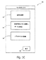
他の実施態様において、図1Cに示されるように、受信装置/記録装置30、および/またはワークステーション50、および/または携帯型の装置40は、ソフトウェアとオペレーティングシステム、あるいは、他の命令を含み得るものであり、それらは、装置4から送信されているデータあるいは画像について、表示、分析あるいは処理する能力を与えることができる。
In other embodiments, as shown in FIG. 1C, the receiver /
この発明のある実施態様によると、オペレーティングシステムは、1またはそれよりも多い手続を実行するための「ツールボックス」画面90のような情報表示を含み得る。た
とえば、画面90は、患者受付ボックス92と、「着脱可能なメモリ装置にデータを転送」ボックス94と、リアルタイム表示ボックス96と、終了ボックス98とを含み得る。他の機能が含まれていてもよい。
According to one embodiment of the invention, the operating system may include an information display such as a “toolbox”
図2は、この発明のある実施態様に従う生体内検知システム2の例示的なブロック図である。この発明のある実施態様に従うと、生体内検知システム2は、生体内検知装置4と、受信装置/記録装置230と、携帯型の装置251とを含み得るものであり、それはワークステーションであり、あるいはワークステーションに含まれ得る。
FIG. 2 is an exemplary block diagram of an in-
この発明のある実施態様に従うと、検出装置4は、容器あるいは筐体241を含み得る。この発明の一実施態様に従うと、筐体の内部に、たとえば、撮像システム218と、制御ブロック220と、送信装置222と、受信装置224とアンテナ226とが含まれ得る。この発明の一実施態様に従うと、検知装置4は、少なくとも、撮像システム218と制御ブロック220と送信装置222と任意の受信装置224に対して電力を供給するための電源228を含み得る。
According to an embodiment of the present invention, the detection device 4 may include a container or
この発明の一実施態様に従うと、すべての構成部品は、検知装置4の筐体に密封され得るものであり(その筐体あるいはシェルは1つ以上の部品を含み得る)、たとえば、撮像システム、電源、ならびに送信および制御システムは、すべて、検知装置4の筐体の内部で密封され得る。 According to one embodiment of the present invention, all components can be sealed in the housing of the sensing device 4 (the housing or shell can include one or more components), for example, an imaging system, The power supply and transmission and control system can all be sealed inside the housing of the sensing device 4.
この発明の一実施態様に従うと、検知装置4は、典型的には、自発的に飲み下すことが可能なカプセルであってもよく、あるいはカプセルを含んでもよいが、装置4は、他の形状を有していてもよく、また飲み下せなくても、あるいは自発的でなくてもよい。装置4の実施例は、典型的には、自発的であり、あるいは典型的には内蔵型である。たとえば、装置4は、カプセル、あるいは、容器あるいはシェルの中に実質的にすべての構成部品が含まれる他の装置でもよい。そして、装置4がたとえば電力の供給を受け、あるいは情報を送信するために、いかなる有線あるいはケーブルを必要としない他の装置であってもよい。 According to one embodiment of the invention, the sensing device 4 may typically be a capsule that can be swallowed spontaneously, or it may comprise a capsule, but the device 4 may have other shapes. It may have, may not be swallowed, or may not be spontaneous. Embodiments of device 4 are typically spontaneous or typically self-contained. For example, the device 4 may be a capsule or other device in which substantially all components are contained in a container or shell. The device 4 may be another device that does not require any wire or cable to receive power supply or transmit information, for example.
この発明のある実施態様に従うと、送信装置222は、たとえば装置4のさまざまな動作を制御するための制御機能を含み得るが、制御能力あるいは、1つ又はそれよりも多い制御の局面が離れた構成部品に含まれてもよい。
According to certain embodiments of the present invention, the
この発明の一実施態様に従うと、電源228は、たとえば酸化銀バッテリ、リチウム電池、コンデンサ、あるいは他の適切な電源のようなバッテリを含み得る。この発明の他の実施態様において、電源228は存在しなくてもよく、当該装置は、たとえばその装置に対して伝わる磁界あるいは電界によって、外部の電源によって電力の供給を受けてもよい。
According to one embodiment of the invention,
撮像システム218は、光学ウインドウ230と、たとえば発光ダイオード(LED)、OLED(有機LED)のような少なくとも1つの発光源232と、イメージングセンサ234と、光学系236とを含み得る。
The
イメージングセンサ234は、固体イメージングセンサ、相補型金属酸化膜半導体(complementary metal oxide semiconductor(CMOS))イメージングセンサ、電荷結合素子(charge coupled device(CCD))イメージングセンサ、リニアイメージングセンサと、ラインイメージングセンサと、フレームイメージングセンサ、「カメラオンチップ」イメージングセンサ、または他の適切なイメージングセンサを含み得る。
The
この発明のある実施態様に従うと、制御ブロック220は、少なくとも部分的には、検知装置4の動作を制御し得る。たとえば、制御ブロック220は、発光源232が光線を生成する時間間隔と、イメージングセンサ234が画像を撮像する時間間隔と、送信装置22がその画像を送信する時間間隔とを同期させる。加えて、制御ブロック220は、送信装置222と光学受信装置224とイメージングセンサ234との動作に必要なタイミング信号あるいは他の信号を生成し得る。さらに、制御ブロック220は、たとえば画像データバッファリングのように検知装置4の他の構成要素によって実行される動作を補うための動作を、実行し得る。
According to an embodiment of the invention, the
この発明のある実施態様に従うと、制御ブロック220は、たとえば組み合せ論理、ステートマシン、コントローラ、プロセッサ、メモリ要素その他のような論理コンポーネントのいかなる組み合せも含み得る。 According to certain embodiments of the present invention, control block 220 may include any combination of logic components such as combinational logic, state machines, controllers, processors, memory elements, and the like.
制御ブロック220と送信装置222と受信装置224とイメージングセンサ234とは、半導体のダイのいかなる組み合せにおいても実現され得る。たとえば、そしてこの発明はこの点に限られないけれども、制御ブロック220と送信装置222と受信装置224とは、第1の半導体のダイの一部であってもよく、また、イメージングセンサ234は、第2の半導体のダイの一部であってもよい。さらに、そのような半導体のダイは、特定用途向け集積回路(application-specific integrated circuit(ASIC))であってもよく、あるいは、特定用途向け汎用集積回路(application-specific standard product(ASSP))の一部であってもよい。ある実施態様に従うと、ダイは積み重ねられてもよい。ある実施態様に従うと、当該構成部品のいくつかあるいはすべては、同じダイの上にあってもよい。
この発明のある実施態様に従うと、発光源232は、光学ウインドウ231を透過することができ、かつ、人体の内腔の内部240を照射することができる光線238を発生し得る。人体の内腔の一例の網羅的でない一覧は、胃腸管(GI)と、血管と、生殖器官と他の妥当な人体の内腔とを含み得る。
According to certain embodiments of the invention, the
人体の内腔の内部240からの光線238の反射光242は、光学ウインドウ230を透過して検知装置4に戻り得るものであり、光学系236によってイメージングセンサ234上で焦点が合わされ得る。この発明のある実施態様に従うと、イメージングセンサ234はその焦点が合った反射光242を受信し得るものであり、制御ブロック220からの画像取得コマンド244に応答して、イメージングセンサ234は、人体の内腔の内部240の画像をキャプチャし得る。この発明のある実施態様に従うと、制御ブロック220は、有線246を介して、イメージングセンサ234から内部240の画像を受信し得るものであり、アンテナ226を介して無線媒体210に対して内部240の画像を送信するために送信装置222を制御することができる。
The reflected light 242 of the
検知装置4は、人体の内腔の軸に沿って、受動的にあるいは能動的に前進し得る。その前進に実質的に同等であり、あるいはなくてもよく、また、関連付けられ、もしくは関連付けられない時間の間隔ごとに、制御ブロック220は、イメージングセンサ234による画像の取得を開始し得るものであり、そして、その取得された画像を送信するために送信装置222を制御することができる。結果として、その人体の内腔の内部のストリーム画像は、検知装置4から無線媒体210を介して送信され得る。
The sensing device 4 can be advanced passively or actively along the axis of the body lumen. The
装置4は、「無線通信フレーム」に組み込まれた取得画像を送信し得る。無線通信フレームのペイロード部は、取得された画像を含み得るものであり、たとえばテレメトリー情報、および/または、巡回冗長コード(cyclic redundancy code(CRC))および/または、エラー訂正符号(ECC)のような付加データを含み得る。加えて、無線通信フレ
ームは、オーバーヘッド部を含み得るものであり、それは、たとえば、フレーミングビット、同期ビット、プリアンブルビットなどを含み得る。
The device 4 may transmit the acquired image embedded in the “wireless communication frame”. The payload portion of the wireless communication frame may include the acquired image, such as telemetry information and / or cyclic redundancy code (CRC) and / or error correction code (ECC). Additional data may be included. In addition, a wireless communication frame may include an overhead portion, which may include, for example, framing bits, synchronization bits, preamble bits, and the like.
この発明のある実施態様に従うと、受信装置/記録装置230は、アンテナ248と、たとえばRF受信装置250のような受信装置と、光学送信装置(TX)252と、デジタルモデム254と、メモリコントローラ256と、プロセッサ(uP)258と、たとえばユニバーサルシリアルバス(USB)コントローラ260のような通信コントローラとを含み得る。この発明の他の実施態様に従うと、送信装置52は、受信装置/記録装置230から独立した装置であってもよい。
According to one embodiment of the invention, the receiver /
この発明のある実施態様に従うと、プロセッサ258は、たとえばバス262を介して、RF受信装置250と、任意の送信装置252と、デジタルモデム254と、メモリコントローラ256と、USBコントローラ260との動作を制御することができる。加えて、RF受信装置250と、任意の送信装置252と、デジタルモデム254と、メモリコントローラ256と、プロセッサ258と、USBコントローラ260とは、バス262を介して、検知装置4あるいはその各部から受信した画像のようなデータを交換することができる。制御あるいはデータ交換のための他の方法が可能であって当該発明の範囲内であることが、理解され得る。
According to one embodiment of the present invention, processor 258 performs operations of
この発明のある実施態様に従うと、アンテナ248は、受信装置/記録装置230の内部あるいは外部に装着され得るものであり、RF受信装置250と任意の送信装置252とはいずれも、アンテナ248に接続され得る。この発明のある実施態様に従うと、送信装置252は、アンテナ248を介して、無線メッセージを検知装置4に対して送信することができる。この発明のある実施態様に従うと、RF受信装置250は、アンテナ248を介して、検知装置4からの、たとえば、無線通信フレームのストリームのような伝送信号を受信することができ、その受信された無線通信フレームに対応する信号264を出力し得る。
According to one embodiment of the present invention, the
この発明のある実施態様に従うと、デジタルモデム254は、RF受信装置250のサンプリングされたアナログ信号のビット264を受信し得るものであり、そのアナログ信号264から作られたデジタルビット265を出力することができ、たとえば、プロセッサ258によって受信されるペイロード有効指示266を出力することができ。この発明のある実施態様に従うと、ペイロード有効指示266は、ペイロード部(図3の306)の間、たとえば、ハイ(high)論理レベルまで、デジタルモデム254によってアサートされ得るものであり、その他の場合は、たとえばロー(low)論理レベルまでデジタルモデム254によってデ・アサートされ得る。ペイロードビット265は、メモリコントローラ256によって受信され得るものであり、ペイロード有効指示266は、プロセッサ258によって受信され得る。
According to one embodiment of the invention, the digital modem 254 is capable of receiving the sampled
メモリコントローラ256は、書込ダイレクトメモリアクセス(write direct memory access(DMA))コントローラ268と、読取DMAコントローラ270と、ヘッダ記憶部272と、書込ページポインタ記憶部274と、読取ページポインタ記憶部276と、読取/書込バーストサイズ記憶部277とを含み得る。ペイロード有効指示266のアサートに応答して、プロセッサ258は、書込ページポインタ記憶部274に、メモリ212のページに対するポインタを格納することができ、任意に、ヘッダを、ヘッダ記憶部272に格納し得る。加えて、プロセッサ258は、デジタルモデム254から無線通信フレームのペイロードビット265を受信するために、書込DMAコントローラ268を起動することができ、そのペイロードビット265をメモリ212に保存し得る。この発明のある実施態様に従うと、受信装置/記録装置230は、媒体214を介して、ワークステーション251および/または携帯型の装置と通信することができる。たとえば、こ
の発明のある実施態様に従うと、受信装置/記録装置230は、メモリ212に記録されているペイロードをワークステーション251に転送することができ、また、ワークステーション251から制御信号を受信することができる。この発明はこの点に限られるものではないが、媒体214は、たとえばUSBケーブルであってもよく、受信装置/記録装置230のUSBコントローラ260または装置251のUSBコントローラ280に接続されてもよい。代替的に、媒体214は、無線であってもよく、受信装置/記録装置230および装置251は、無線で通信し得る。
The
この発明のある実施態様に従うと、受信装置/記録装置230は、USBコントローラ260あるいは他の適切なリンクを介して、検知装置4から装置251に受信されたようにストリームのペイロードの送信をたとえば開始するための制御信号を、装置251から受信し得るものであり、そのストリームの特定のペイロードにおいて開始する。USBコントローラ60は、その制御信号を、バス62を介して、プロセッサ58に転送し得る。
According to one embodiment of the invention, the receiver /
この発明のある実施態様に従うと、装置251から受信した制御信号に応答して、プロセッサ258は、メモリコントローラ256およびUSBコントローラ260をプログラムして、読取DMAコントローラ270が装置251によって要求された順番に、メモリ212からペイロードをフェッチし、そのフェッチしたペイロードをUSBコントローラ260に送り、かつ、USBコントローラ260がそのフェッチされたペイロードを装置251に送信する。たとえば、プロセッサ258は、読取ページポインタ記憶部276に対して、読取DMAコントローラ270がメモリ212のどこからペイロードのフェッチを開始することができるかの部分に対するポインタを書き込むことができる。加えて、プロセッサ258は、読取/書込バーストサイズ記憶部277に対して、読取DMAコントローラ270が一度のバーストによってフェッチできるメモリ212の部分の数を書き込み得る。
According to one embodiment of the invention, in response to a control signal received from
読取DMAコントローラ270は、書込DMAコントローラ268がメモリ212にアクセスしていない間に、記録されているペイロードをフェッチするために、メモリバス278を介して、メモリ212にアクセスし得る。少なくともこの目的のために、書込DMAコントローラ268は、たとえば、指示284を読取DMAコントローラ270に出力し得る。この発明のある実施態様に従うと、書込DMAコントローラ268は、ペイロード有効指示266のアサートに応答して、たとえば指示284をハイ論理レベルにアサートし得る。そして、たとえば、当該ヘッダをメモリ212に書き込むことが完了した後に、指示284をロー論理レベルにデ・アサートし得る。この発明のある実施態様に従うと、読取DMAコントローラ270は、指示284がデ・アサートされた後に、メモリ212から、記録されているペイロードのフェッチを開始することができ、そして、メモリ212から、読取/書込バーストサイズ記憶部277に格納されている数に等しい部分の数をフェッチすることができる。
Read
たとえば、この発明のある実施態様に従うと、読取/書込バーストサイズ記憶部277に格納されている数は、読取ページポインタ記憶部276に格納されているポインタの数に、および/または、読取DMAコントローラ270がメモリ212から記録されているペイロードをフェッチするために利用可能な時間に、関連付けられ得る。
For example, according to one embodiment of the present invention, the number stored in read / write
読取DMAコントローラ270は、たとえばバス262を介して、バーストの終了をプロセッサ258に通知するために、指示をプロセッサ258に送信し得る。
Read
ある実施態様に従うと、そのメモリにおける逆方向および順方向への動きはイネーブルされ得る。他の実施態様に従うと、データは、デジタルモデム254からUSBコントローラ260に直接に送信(たとえば、フェッチ)され得る。したがって、読取DMA27
0に対する書き込みは必要でなくなり得る。ある実施態様に従うと、読取DMA270は、受信装置/記録装置230に含まれている必要がない。
According to an embodiment, backward and forward movement in the memory can be enabled. According to other embodiments, data may be sent (eg, fetched) directly from the digital modem 254 to the
Writing to 0 may not be necessary. According to certain embodiments, the
装置251は、プロセッサ286と、たとえばマウスあるいはキーボードのような少なくとも1つのヒューマンインターフェイス装置(human interface device(HID))288と、メモリ290と、ディスプレイ装置216に接続される表示コントローラ292とを含み得る。
The
この発明のある実施態様に従うと、プロセッサ258は、バス294を介して、USBコントローラ280、HID288、メモリ290および表示コントローラ292の動作を制御することができる。加えて、USBコントローラ280とプロセッサ286とHID288とメモリ290と表示コントローラ292とは、バス294を介して、たとえば受信装置/記録装置230から受信した無線通信フレームのペイロード、あるいは、その受信装置/記録装置230の部分から受信した無線通信フレームのペイロードのようなデータを、交換することができる。
According to one embodiment of the present invention, the processor 258 can control the operation of the
この発明のある実施態様に従うと、受信装置/記録装置230から受信した無線通信フレームのペイロードは、バス294を介して、あるいはプロセッサ286によって、USBコントローラ280からメモリ290に対して、DMAプロセスにおいて転送され得る。
According to one embodiment of the present invention, the payload of the wireless communication frame received from the receiver /
この発明のある実施態様に従うと、画像は、メモリ290に格納されているペイロードから抽出されてもよく、表示されるために表示コントローラ292によってディスプレイ装置216に転送されてもよく、および/または、プロセッサ286によって分析されてもよい。
According to certain embodiments of the invention, the image may be extracted from a payload stored in
プロセッサ258および286の一例の網羅的でない一覧は、中央処理装置(central processing unit(CPU))、デジタル信号プロセッサ(digital signal processor(DSP))、縮小命令セットコンピュータ(reduced instruction set computer(RISC))、複雑命令セットコンピュータ(complex instruction set computer(CISC))等を含む。さらに、プロセッサ220,258および/または286は、特定用途向け集積回路(application specific integrated circuit(ASIC))の一部であってもよく、あるいは、各々特定用途向け汎用集積回路(application specific standard product(ASSP))の一部であってもよい。
An example non-exhaustive list of
装置251の一例の網羅的でない一覧は、OEM(original equipment manufacturer)向けのワークステーション、デスクトップ型のパーソナルコンピュータ、サーバコンピュータ、ラップトプコンピュータ、パーソナルデジタルアシスタント、ノートブックコンピュータ、携帯型のコンピュータ等を含み得る。
An example non-exhaustive list of
次に、この発明の実施態様に従う生体内検知システム2において生じ得るイベントを表わす、単純化されたタイミング図である図3が参照される。
Reference is now made to FIG. 3, which is a simplified timing diagram representing events that may occur in the in-
この発明のある実施態様に従うと、検知装置4によって送信される無線通信フレームの例示的なペイロードは、たとえば256画素×256画素およびECCからなる取得された画像を含み得る。検知装置4は、たとえば、500ミリ秒(mS)の実質的に等しいフレーム時間間隔(300)について1秒当たり2つの無線通信フレームを送信し得る。フレームタイム間隔の送信部分(302)の間、検知装置4は、無線通信フレームを送信することができ、フレーム時間間隔の停止部分(304)の間、検知装置4は、送信することができない。加えて、送信部分(302)のうちのペイロード部分(306)の間、検
知装置4は、無線通信フレームのペイロードを送信することができ、一方、送信部(302)の残りの間、検知装置4は、無線通信フレームのオーバーヘッドを送信することができる。他の実施態様に従うと、停止部分(304)は、必要でなくてもよい。フェッチ動作および送信は、たとえば以下に述べられるように、送信期間(302)の間ほとんど同時に実行され得る。
According to an embodiment of the present invention, an exemplary payload of a wireless communication frame transmitted by the sensing device 4 may include an acquired image consisting of, for example, 256 pixels × 256 pixels and ECC. The sensing device 4 may transmit two wireless communication frames per second for a substantially equal frame time interval (300) of, for example, 500 milliseconds (mS). During the transmission portion (302) of the frame time interval, the detection device 4 can transmit a wireless communication frame, and during the stop portion (304) of the frame time interval, the detection device 4 cannot transmit. In addition, during the payload portion (306) of the transmission portion (302), the detection device 4 can transmit the payload of the wireless communication frame, while the detection device during the remainder of the transmission unit (302). 4 can transmit the overhead of the radio communication frame. According to other embodiments, the stop portion (304) may not be necessary. The fetch operation and transmission can be performed almost simultaneously during the transmission period (302), eg, as described below.
この発明のある実施態様に従うと、任意の受信装置224は、アンテナ226によって無線媒体210を介して無線メッセージを受信することができ、制御ブロック220は、これらのメッセージを取得することができる。そのようなメッセージの一例の網羅的でない一覧は、検知装置4による撮像を有効にすること又は無効にすること、画像の撮影のためのタイムインターバルを制御すること、検知装置4からの送信を有効にすること又は無効にすること、その他の適切なメッセージを含む。
In accordance with certain embodiments of the present invention, any receiving
この発明のある実施態様に従うと、書込DMAコントローラ268は、ペイロードビット265を受信することができ、メモリバス278を介してメモリ212にアクセスすることができ、書込ページポインタ記憶部274に格納されているポインタによって示されるメモリ212の部分に、ペイロードビット265を格納し得る。ペイロード有効指示266の後に続くデ・アサートに応答して、プロセッサ258は、ペイロードビット265の終わりを示すために制御信号をメモリコントローラ256に送信し得る。応答して、書込DMAコントローラ268は、ペイロードビット265の最後のバイトに、あるいはメモリ212における最初のバイトの前に、ヘッダ記憶部272に格納されているヘッダを付加してもよく、そして、その動作を終了することができる。この発明のある実施態様に従うと、図3に示されるように、実質的に重複するペイロード部分(306)のタイムインターバルの間、RF受信装置250によって受信されたペイロードは、メモリ212に格納され、一方、ペイロード(306)に加えられるタイムインターバル(308)の間、ヘッダ記憶部272に格納されているヘッダは、メモリ212に格納される。
According to one embodiment of the present invention, write
この発明のある実施態様に従うと、ペイロードビット26を独立してメモリ212に格納するために書込DMAコントローラ268を駆動しているプロセッサ258のプロセスは、一連の無線通信フレームのフレームについて反復し得る。さらに、検知装置4から受信されたペイロードの順序は、メモリ212において追跡可能であってもよい。
According to one embodiment of the invention, the process of processor 258 driving
次に、この発明のある実施態様に従って検知装置の動作のタイミング図を表わす概念的な図である図4Aおよび4Bが参照される。この発明のある実施態様に従うと、図4Aに示されるように、全体の記録期間410、すなわち受信装置/記録装置6によってメモリ12に対して検知装置4から受信した情報を記録することは、時刻Tにおいて始まり、時刻T1において終了し得る。ダウンロード/処理期間420および同時に表示する期間440、たとえば受信装置/記録装置6からワークステーション50に対して情報をダウンロードすることおよびその情報を表示することは、時刻T1において始まり、時刻T2において終了し得る。ある実施態様に従うと、受信装置/記録装置6は、メモリ12にその情報を記録してもよく(記録期間410)、その後に、その情報を処理し、および/またはディスプレイ装置18のようなディスプレイ装置にその情報を表示してもよい(ダウンロード/処理期間420および表示期間430)。
Reference is now made to FIGS. 4A and 4B, which are conceptual diagrams representing timing diagrams of operation of the sensing device in accordance with an embodiment of the present invention. According to one embodiment of the present invention, as shown in FIG. 4A, recording the information received from the sensing device 4 to the
この発明のある実施態様に従うと、たとえば図4Bに示されるように、記録期間440、ダウンロード/処理期間450および表示期間460はすべて、時刻Tにおいて開始し、時刻T1において終了し得る。たとえば、生体内検知システムは、ストリーム画像のような情報を同時に記録し、ダウンロードし、表示してもよく、したがって、当該検知装置が患者の体内に存在する間に、その患者の内腔のリアルタイムの表示を可能にすることができる。
According to one embodiment of the invention, as shown, for example, in FIG. 4B, the
この発明の一実施態様に従うと、受信装置/記録装置6は、メモリ12のようなメモリに検知装置4から受信した情報を記録し、その情報を処理し、かつディスプレイ装置18のような表示装置にその情報を(図1Aに示されるように)表示することを同時に行なってもよい。
According to one embodiment of the present invention, the receiving device /
この発明の他の実施態様に従うと、受信装置/記録装置6は、メモリ32のようなメモリに検知装置4から受信した情報を記録し、そのメモリからワークステーション50あるいは携帯型の装置にその情報をダウンロードすることを同時に行なってもよい。その情報は、ダウンロード/処理期間450および記録期間440の間、ディスプレイ装置46のような表示装置に同時に表示されてもよい。
According to another embodiment of the present invention, the receiving device /
この発明のある実施態様に従うと、制御ボタンがディスプレイ装置18のような表示装置に含まれていてもよく、当該検知装置が患者の体内に存在する間、また、記録期間440およびダウンロード/処理期間450の間、たとえば、リアルタイムで、ユーザがたとえばストリーム画像の早送り、巻戻し、再生の停止、あるいは先頭もしくは終了への移動を可能にしてもよい。
According to certain embodiments of the present invention, control buttons may be included in a display device, such as
図5Aは、この発明のある実施態様に従って、生体内検知装置によって集められたたとえばストリーム画像の情報を同時に受信しおよび表示するための方法の概念的なフローチャートである。ステップ510にて、情報、たとえばストリームの画像は、検知装置4が患者の体内に存在する間、たとえば受信装置/記録装置6を使用することによって検知装置4から受信され得る。ステップ520にて、その情報は、受信装置/記録装置6によって、たとえばメモリ12に記録され得る。ステップ530にて、その情報は、その受信装置/記録装置によって処理され、および/または、たとえばメモリ12からワークステーションにダウンロードされ得るものであり、同時に、たとえばディスプレイ装置46に(たとえば図1Bに示されるように)表示され得る。
FIG. 5A is a conceptual flowchart of a method for simultaneously receiving and displaying, for example, stream image information collected by an in-vivo sensing device, according to an embodiment of the present invention. At
図5Bは、この発明のある実施態様に従って生体内の場所をリアルタイムで表示するための方法の概念的なフローチャートである。ステップ560にて、情報は、たとえば受信装置/記録装置6を使用することによって、検知装置から受信され得る。ステップ570にて、その検知装置によって送信された情報は、同時に、メモリに記録され、その受信装置/記録装置によって処理され、および/またはそのメモリからたとえばワークステーション50にダウンロードされ得る。その情報は、受信装置/記録装置がその情報を記録し処理しあるいはダウンロードしている間、たとえばディスプレイ装置46に表示され得るものであり、これにより、検知装置4が患者の体内に存在する間もリアルタイム表示が可能になる。
FIG. 5B is a conceptual flowchart of a method for displaying in-vivo locations in real time in accordance with an embodiment of the present invention. At
図6は、この発明のある実施態様に従って情報を受信するための方法の例示的で簡略化された概念的なフローチャートの一例である。ステップ610にて、情報、たとえばストリームの画像は、たとえば受信装置/記録装置30を使用することによって検知装置4から受信され得る。その間、検知装置4は患者の体内に存在している。ステップ620にて、その情報は、メモリ32のようなメモリに、(図1Bに示されるように)たとえば受信装置/記録装置6を用いて記録される。ステップ630にて、その情報は、たとえばメモリ32から5ギガのディスクオンキー(5G DiskonKey)のような着脱可能なメモリにダウンロードされ得る。ある実施態様に従うと、その情報は、受信装置/記録装置30によって同時に記録されてもよく、たとえば着脱可能なメモリ60によってダウンロードされてもよい。ステップ640にて、ダウンロードされたその情報は、たとえば、患者のチェックイン情報あるいは他の情報とともに処理のための中央サイトに送られ得る。当該中央サイトは、たとえば、生体内検知装置4から得られたデータをプレビューするための訓
練を受けた、健康についての専門家を擁する病院あるいは読み取りセンターなどであり得る。
FIG. 6 is an example of an exemplary simplified conceptual flowchart of a method for receiving information in accordance with an embodiment of the present invention. At
図7は、この発明のある実施態様に従う、データを受信するための方法について例示的で簡略化された概念的なフローチャートの例示である。ステップ710にて、ユーザあるいはオペレータは、たとえば胃腸管あるいは生体内センサが患者の体内にある患者のその胃腸管の他の範囲に従って、体の範囲にわたって受信装置/記録装置を移動させ得る。
FIG. 7 is an illustration of an exemplary and simplified conceptual flowchart for a method for receiving data, in accordance with an embodiment of the present invention. At
ステップ720にて、生体内センサのおおよその位置がたとえば当該受信装置/記録装置の位置に基づいて、当該センサからの信号がその受信装置/記録装置によって受信されたときに決定され得る。たとえば、ユーザは、その患者の腹部にわたって、その受信装置/記録装置をあてがうことができ、画像がディスプレイ装置に現われたときにそれを停止する。ある実施態様においては、位置の決定は、行なわれなくてもよい。
At
ステップ730にて、受信装置/記録装置は、当該生体内センサから受信された画像あるいはその他の情報を表示し得る。
At
ある実施態様においては、画像は、記録され、あるいは当該受信装置/記録装置から、たとえば携帯電話のあるいは他の電磁波によってメモリにあるいは遠隔地にいるユーザに送信され得る。 In some embodiments, the image can be recorded or transmitted from the receiver / recorder to a user at a remote location, for example by a mobile phone or other electromagnetic waves.
この発明のある特徴がここに示され述べられてきたが、多くの変形、置換、変更あるいは均等物がこの分野における当業者の心に浮かぶであろう。したがって、添付されたクレームは、この発明の精神の中に含まれるそのような全ての修正を含むことが意図されていることが理解されるべきである。 While certain features of the invention have been shown and described herein, many modifications, substitutions, changes, or equivalents will occur to those skilled in the art. Therefore, it is to be understood that the appended claims are intended to cover all such modifications as fall within the spirit of this invention.
Claims (10)
発光源と、
イメージングセンサと、
送信装置と、
発光源が光線を生成する期間、イメージングセンサが画像を撮像する期間、および送信装置が前記画像を送信する期間からなる群から選択される期間を同期させるとともに、画像データバッファリングを実行する制御ブロックと、
検知装置内に配置され、制御ブロックに対する制御メッセージを無線受信する内部受信装置とを含み、さらに、
前記検知装置から画像を受信するための外部受信装置と、
前記検知装置が患者の体内に存在する間に、選択された画像を選択された順にダウンロードするとともにダウンロードされた画像を表示するように、前記外部受信装置を制御する、携帯型の装置と、
を備える、生体内検知システム。An in-vivo detection device, the in-vivo detection device,
A light source;
An imaging sensor;
A transmitting device;
A control block that synchronizes a period selected from the group consisting of a period during which the light source generates light, a period during which the imaging sensor captures an image, and a period during which the transmission device transmits the image, and executes image data buffering When,
An internal receiving device disposed within the sensing device and wirelessly receiving a control message for the control block;
An external receiving device for receiving an image from the sensing device;
A portable device that controls the external receiving device to download selected images in the selected order and display the downloaded images while the sensing device is in the patient's body;
An in-vivo detection system comprising:
を同時に実行する、請求項4に記載のシステム。The external reception device records an image of a stream image received from the in-vivo detection device in a memory, downloads the image from the memory to the workstation, and transmits the image to the workstation. The system according to claim 4, wherein the display on the display is performed simultaneously.
Applications Claiming Priority (5)
| Application Number | Priority Date | Filing Date | Title |
|---|---|---|---|
| US58388204P | 2004-06-30 | 2004-06-30 | |
| US60/583,882 | 2004-06-30 | ||
| US66707405P | 2005-04-01 | 2005-04-01 | |
| US60/667,074 | 2005-04-01 | ||
| PCT/IL2005/000696 WO2006003650A2 (en) | 2004-06-30 | 2005-06-30 | In-vivo sensing system device and method for real time viewing |
Publications (3)
| Publication Number | Publication Date |
|---|---|
| JP2008504922A JP2008504922A (en) | 2008-02-21 |
| JP2008504922A5 JP2008504922A5 (en) | 2008-08-21 |
| JP4820365B2 true JP4820365B2 (en) | 2011-11-24 |
Family
ID=35783227
Family Applications (1)
| Application Number | Title | Priority Date | Filing Date |
|---|---|---|---|
| JP2007519975A Active JP4820365B2 (en) | 2004-06-30 | 2005-06-30 | In-vivo detection system apparatus and method for real-time display |
Country Status (4)
| Country | Link |
|---|---|
| US (1) | US20080262304A1 (en) |
| EP (1) | EP1765144B1 (en) |
| JP (1) | JP4820365B2 (en) |
| WO (1) | WO2006003650A2 (en) |
Families Citing this family (9)
| Publication number | Priority date | Publication date | Assignee | Title |
|---|---|---|---|---|
| EP1942800B1 (en) * | 2005-09-09 | 2011-09-07 | Given Imaging Ltd. | Concurrent transfer and processing and real time viewing of in-vivo images |
| ES2476999T3 (en) | 2005-10-11 | 2014-07-15 | Impedimed Limited | Hydration Status Monitoring |
| JP4956287B2 (en) * | 2007-06-06 | 2012-06-20 | オリンパスメディカルシステムズ株式会社 | Capsule endoscope system and program |
| US20100186234A1 (en) | 2009-01-28 | 2010-07-29 | Yehuda Binder | Electric shaver with imaging capability |
| WO2011073987A1 (en) | 2009-12-17 | 2011-06-23 | Given Imaging Ltd. | Device, system and method for activation, calibration and testing of an in-vivo imaging device |
| EP2624745A4 (en) * | 2010-10-07 | 2018-05-23 | Abbott Diabetes Care, Inc. | Analyte monitoring devices and methods |
| US11141063B2 (en) * | 2010-12-23 | 2021-10-12 | Philips Image Guided Therapy Corporation | Integrated system architectures and methods of use |
| US9667889B2 (en) * | 2013-04-03 | 2017-05-30 | Butterfly Network, Inc. | Portable electronic devices with integrated imaging capabilities |
| US9747227B1 (en) * | 2013-05-24 | 2017-08-29 | Qlogic, Corporation | Method and system for transmitting information from a network device |
Citations (6)
| Publication number | Priority date | Publication date | Assignee | Title |
|---|---|---|---|---|
| US5604531A (en) * | 1994-01-17 | 1997-02-18 | State Of Israel, Ministry Of Defense, Armament Development Authority | In vivo video camera system |
| JP2001224553A (en) * | 2000-02-17 | 2001-08-21 | Asahi Optical Co Ltd | Imaging instrument for capusle endoscope |
| WO2003011103A2 (en) * | 2001-08-02 | 2003-02-13 | Given Imaging Ltd. | Apparatus and methods for in vivo imaging |
| JP2004073887A (en) * | 2003-11-12 | 2004-03-11 | Olympus Corp | Capsule endoscope |
| JP2004167008A (en) * | 2002-11-20 | 2004-06-17 | Olympus Corp | Body inside observation system |
| JP2005074034A (en) * | 2003-09-01 | 2005-03-24 | Olympus Corp | Capsule endoscope |
Family Cites Families (54)
| Publication number | Priority date | Publication date | Assignee | Title |
|---|---|---|---|---|
| JPS5519124A (en) * | 1978-07-27 | 1980-02-09 | Olympus Optical Co | Camera system for medical treatment |
| US5993378A (en) * | 1980-10-28 | 1999-11-30 | Lemelson; Jerome H. | Electro-optical instruments and methods for treating disease |
| EP0526064B1 (en) * | 1991-08-02 | 1997-09-10 | The Grass Valley Group, Inc. | Video editing system operator interface for visualization and interactive control of video material |
| US5819736A (en) * | 1994-03-24 | 1998-10-13 | Sightline Technologies Ltd. | Viewing method and apparatus particularly useful for viewing the interior of the large intestine |
| US6310642B1 (en) * | 1997-11-24 | 2001-10-30 | Micro-Medical Devices, Inc. | Reduced area imaging devices incorporated within surgical instruments |
| US6982742B2 (en) * | 1997-10-06 | 2006-01-03 | Adair Edwin L | Hand-held computers incorporating reduced area imaging devices |
| US6240312B1 (en) * | 1997-10-23 | 2001-05-29 | Robert R. Alfano | Remote-controllable, micro-scale device for use in in vivo medical diagnosis and/or treatment |
| US8636648B2 (en) * | 1999-03-01 | 2014-01-28 | West View Research, Llc | Endoscopic smart probe |
| US7813789B2 (en) * | 1999-06-15 | 2010-10-12 | Given Imaging Ltd. | In-vivo imaging device, optical system and method |
| US6474341B1 (en) * | 1999-10-28 | 2002-11-05 | Surgical Navigation Technologies, Inc. | Surgical communication and power system |
| US7039453B2 (en) * | 2000-02-08 | 2006-05-02 | Tarun Mullick | Miniature ingestible capsule |
| EP1693000B1 (en) * | 2000-03-08 | 2013-05-08 | Given Imaging Ltd. | A device for in vivo imaging |
| IL163684A0 (en) * | 2000-05-31 | 2005-12-18 | Given Imaging Ltd | Measurement of electrical characteristics of tissue |
| JP2002304584A (en) * | 2001-04-05 | 2002-10-18 | Olympus Optical Co Ltd | Equipment rental system |
| US7119814B2 (en) * | 2001-05-18 | 2006-10-10 | Given Imaging Ltd. | System and method for annotation on a moving image |
| IL143260A (en) * | 2001-05-20 | 2006-09-05 | Given Imaging Ltd | Array system and method for locating an in vivo signal source |
| US6939292B2 (en) * | 2001-06-20 | 2005-09-06 | Olympus Corporation | Capsule type endoscope |
| AU2002304266A1 (en) * | 2001-06-20 | 2003-01-02 | Given Imaging Ltd. | Motility analysis within a gastrointestinal tract |
| JP2003010112A (en) * | 2001-06-28 | 2003-01-14 | Olympus Optical Co Ltd | Endoscope system |
| US6951536B2 (en) * | 2001-07-30 | 2005-10-04 | Olympus Corporation | Capsule-type medical device and medical system |
| US6648823B2 (en) * | 2001-07-31 | 2003-11-18 | Medtronic, Inc. | Method and system of follow-up support for a medical device |
| JP2003070804A (en) * | 2001-09-05 | 2003-03-11 | Olympus Optical Co Ltd | Remote medical support system |
| JP3974769B2 (en) * | 2001-11-06 | 2007-09-12 | オリンパス株式会社 | Capsule medical device |
| IL153510A0 (en) * | 2001-12-18 | 2003-07-06 | Given Imaging Ltd | Device, system and method for capturing in-vivo images with three-dimensional aspects |
| IL147221A (en) * | 2001-12-20 | 2010-11-30 | Given Imaging Ltd | Device, system and method for image based size analysis |
| US20030158503A1 (en) * | 2002-01-18 | 2003-08-21 | Shinya Matsumoto | Capsule endoscope and observation system that uses it |
| US6939290B2 (en) * | 2002-02-11 | 2005-09-06 | Given Imaging Ltd | Self propelled device having a magnetohydrodynamic propulsion system |
| IL154391A (en) * | 2002-02-11 | 2009-05-04 | Given Imaging Ltd | Self propelled device |
| WO2003069913A1 (en) * | 2002-02-12 | 2003-08-21 | Given Imaging Ltd. | System and method for displaying an image stream |
| JP4363843B2 (en) * | 2002-03-08 | 2009-11-11 | オリンパス株式会社 | Capsule endoscope |
| JP4009473B2 (en) * | 2002-03-08 | 2007-11-14 | オリンパス株式会社 | Capsule endoscope |
| JP3869291B2 (en) * | 2002-03-25 | 2007-01-17 | オリンパス株式会社 | Capsule medical device |
| EP1501415A1 (en) * | 2002-05-09 | 2005-02-02 | Given Imaging Ltd. | System and method for in vivo sensing |
| US7708705B2 (en) * | 2002-07-03 | 2010-05-04 | Given Imaging Ltd. | System and method for sensing in-vivo stress and pressure |
| AU2003274635A1 (en) * | 2002-10-15 | 2004-05-04 | Given Imaging Ltd. | Device, system and method for transfer of signals to a moving device |
| US7252633B2 (en) * | 2002-10-18 | 2007-08-07 | Olympus Corporation | Remote controllable endoscope system |
| JP2004167163A (en) * | 2002-11-22 | 2004-06-17 | Olympus Corp | Capsule type medical care system |
| JP4503930B2 (en) * | 2003-01-30 | 2010-07-14 | オリンパス株式会社 | Medical equipment |
| JP4149838B2 (en) * | 2003-03-04 | 2008-09-17 | オリンパス株式会社 | Capsule medical device |
| JP4012097B2 (en) * | 2003-03-06 | 2007-11-21 | オリンパス株式会社 | Capsule type medical device collection device |
| DE10318205A1 (en) * | 2003-04-22 | 2004-11-25 | Siemens Ag | Computer supported 3-D imaging for capsule endoscope takes sequence of single images and processes them using overlapping pattern recognition algorithm to display surroundings |
| CA2523288C (en) * | 2003-04-25 | 2009-06-23 | Olympus Corporation | Wireless in-vivo information acquiring system and body-insertable device |
| JP4328125B2 (en) * | 2003-04-25 | 2009-09-09 | オリンパス株式会社 | Capsule endoscope apparatus and capsule endoscope system |
| JP3810381B2 (en) * | 2003-04-25 | 2006-08-16 | オリンパス株式会社 | Image display device, image display method, and image display program |
| CA2523309C (en) * | 2003-04-25 | 2009-01-06 | Olympus Corporation | Capsule endoscope and capsule endoscope system |
| CN101264001B (en) * | 2003-04-25 | 2010-11-10 | 奥林巴斯株式会社 | Image display apparatus |
| JP4402655B2 (en) * | 2003-05-14 | 2010-01-20 | オリンパス株式会社 | Capsule medical device |
| DE10323216B3 (en) * | 2003-05-22 | 2004-12-23 | Siemens Ag | Endoscope apparatus has cameras which are provided at respective ends of endoscope capsule, such that one of camera is tilted or rotated to change photography range |
| WO2004112592A1 (en) * | 2003-06-24 | 2004-12-29 | Olympus Corporation | Capsule type medical device communication system, capsule type medical device, and biological information reception device |
| US7319781B2 (en) * | 2003-10-06 | 2008-01-15 | Carestream Health, Inc. | Method and system for multiple passes diagnostic alignment for in vivo images |
| US8082024B2 (en) * | 2004-01-16 | 2011-12-20 | Alfano Robert R | Micro-scale compact device for in vivo medical diagnosis combining optical imaging and point fluorescence spectroscopy |
| US20050192478A1 (en) * | 2004-02-27 | 2005-09-01 | Williams James P. | System and method for endoscopic optical constrast imaging using an endo-robot |
| US20060095093A1 (en) * | 2004-11-04 | 2006-05-04 | Ido Bettesh | Apparatus and method for receiving device selection and combining |
| JP4981316B2 (en) * | 2005-12-16 | 2012-07-18 | オリンパスメディカルシステムズ株式会社 | Intra-subject introduction device |
-
2005
- 2005-06-30 WO PCT/IL2005/000696 patent/WO2006003650A2/en active Application Filing
- 2005-06-30 US US11/631,367 patent/US20080262304A1/en not_active Abandoned
- 2005-06-30 EP EP05756914.7A patent/EP1765144B1/en active Active
- 2005-06-30 JP JP2007519975A patent/JP4820365B2/en active Active
Patent Citations (6)
| Publication number | Priority date | Publication date | Assignee | Title |
|---|---|---|---|---|
| US5604531A (en) * | 1994-01-17 | 1997-02-18 | State Of Israel, Ministry Of Defense, Armament Development Authority | In vivo video camera system |
| JP2001224553A (en) * | 2000-02-17 | 2001-08-21 | Asahi Optical Co Ltd | Imaging instrument for capusle endoscope |
| WO2003011103A2 (en) * | 2001-08-02 | 2003-02-13 | Given Imaging Ltd. | Apparatus and methods for in vivo imaging |
| JP2004167008A (en) * | 2002-11-20 | 2004-06-17 | Olympus Corp | Body inside observation system |
| JP2005074034A (en) * | 2003-09-01 | 2005-03-24 | Olympus Corp | Capsule endoscope |
| JP2004073887A (en) * | 2003-11-12 | 2004-03-11 | Olympus Corp | Capsule endoscope |
Also Published As
| Publication number | Publication date |
|---|---|
| US20080262304A1 (en) | 2008-10-23 |
| EP1765144A2 (en) | 2007-03-28 |
| JP2008504922A (en) | 2008-02-21 |
| EP1765144A4 (en) | 2008-07-02 |
| WO2006003650A3 (en) | 2006-08-31 |
| WO2006003650A2 (en) | 2006-01-12 |
| EP1765144B1 (en) | 2015-11-18 |
Similar Documents
| Publication | Publication Date | Title |
|---|---|---|
| JP4820365B2 (en) | In-vivo detection system apparatus and method for real-time display | |
| US8043209B2 (en) | System and method for transmitting the content of memory storage in an in-vivo sensing device | |
| US20080004532A1 (en) | System and method for transmitting identification data in an in-vivo sensing device | |
| US11715201B2 (en) | Capsule endoscope for determining lesion area and receiving device | |
| EP1709901A2 (en) | System and method for performing capsule endoscopy in remote sites | |
| US7805178B1 (en) | Device, system and method of receiving and recording and displaying in-vivo data with user entered data | |
| EP2977010B1 (en) | Radiation image capturing system for avoiding interference when using wireless signals between image capturing device, console and hospital information system | |
| US20210076916A1 (en) | Control method and control system for capsule endoscope | |
| US20080108866A1 (en) | Control method for capsule endoscope with memory storage device | |
| JP4552487B2 (en) | Radiation image detection confirmation network system | |
| JP5271710B2 (en) | A system for simultaneously transferring and processing in-vivo images and viewing them in real time | |
| US8098295B2 (en) | In-vivo imaging system device and method with image stream construction using a raw images | |
| KR20180136857A (en) | Capsule endoscope to determine lesion area and receiving device | |
| CN202568200U (en) | Portable electronic anorectum scope | |
| US20100099948A1 (en) | In-vivo information display device, in-vivo information display system, and in-vivo information display method | |
| US20070219413A1 (en) | Capsulated endoscope with memory storage device | |
| JP5294725B2 (en) | Radiation imaging system | |
| US8279059B2 (en) | Data recorder, system and method for transmitting data received from an in-vivo sensing device | |
| US20090313672A1 (en) | Hand-held data recorder, system and method for in-vivo sensing | |
| US20060111758A1 (en) | Apparatus and methods for replacement of files in a receiver of an in-vivo sensing system | |
| US20180000328A1 (en) | Capsule endoscope |
Legal Events
| Date | Code | Title | Description |
|---|---|---|---|
| A521 | Request for written amendment filed |
Free format text: JAPANESE INTERMEDIATE CODE: A523 Effective date: 20080630 |
|
| A621 | Written request for application examination |
Free format text: JAPANESE INTERMEDIATE CODE: A621 Effective date: 20080630 |
|
| RD03 | Notification of appointment of power of attorney |
Free format text: JAPANESE INTERMEDIATE CODE: A7423 Effective date: 20081205 |
|
| A521 | Request for written amendment filed |
Free format text: JAPANESE INTERMEDIATE CODE: A821 Effective date: 20081225 |
|
| RD04 | Notification of resignation of power of attorney |
Free format text: JAPANESE INTERMEDIATE CODE: A7424 Effective date: 20081225 |
|
| A131 | Notification of reasons for refusal |
Free format text: JAPANESE INTERMEDIATE CODE: A131 Effective date: 20101116 |
|
| A601 | Written request for extension of time |
Free format text: JAPANESE INTERMEDIATE CODE: A601 Effective date: 20110216 |
|
| A602 | Written permission of extension of time |
Free format text: JAPANESE INTERMEDIATE CODE: A602 Effective date: 20110223 |
|
| A521 | Request for written amendment filed |
Free format text: JAPANESE INTERMEDIATE CODE: A523 Effective date: 20110225 |
|
| A131 | Notification of reasons for refusal |
Free format text: JAPANESE INTERMEDIATE CODE: A131 Effective date: 20110510 |
|
| A521 | Request for written amendment filed |
Free format text: JAPANESE INTERMEDIATE CODE: A523 Effective date: 20110617 |
|
| TRDD | Decision of grant or rejection written | ||
| A01 | Written decision to grant a patent or to grant a registration (utility model) |
Free format text: JAPANESE INTERMEDIATE CODE: A01 Effective date: 20110830 |
|
| A01 | Written decision to grant a patent or to grant a registration (utility model) |
Free format text: JAPANESE INTERMEDIATE CODE: A01 |
|
| A61 | First payment of annual fees (during grant procedure) |
Free format text: JAPANESE INTERMEDIATE CODE: A61 Effective date: 20110902 |
|
| FPAY | Renewal fee payment (event date is renewal date of database) |
Free format text: PAYMENT UNTIL: 20140909 Year of fee payment: 3 |
|
| R150 | Certificate of patent or registration of utility model |
Ref document number: 4820365 Country of ref document: JP Free format text: JAPANESE INTERMEDIATE CODE: R150 Free format text: JAPANESE INTERMEDIATE CODE: R150 |
|
| R250 | Receipt of annual fees |
Free format text: JAPANESE INTERMEDIATE CODE: R250 |
|
| R250 | Receipt of annual fees |
Free format text: JAPANESE INTERMEDIATE CODE: R250 |
|
| R250 | Receipt of annual fees |
Free format text: JAPANESE INTERMEDIATE CODE: R250 |
|
| R250 | Receipt of annual fees |
Free format text: JAPANESE INTERMEDIATE CODE: R250 |
|
| R250 | Receipt of annual fees |
Free format text: JAPANESE INTERMEDIATE CODE: R250 |
|
| R250 | Receipt of annual fees |
Free format text: JAPANESE INTERMEDIATE CODE: R250 |
|
| R250 | Receipt of annual fees |
Free format text: JAPANESE INTERMEDIATE CODE: R250 |
|
| R250 | Receipt of annual fees |
Free format text: JAPANESE INTERMEDIATE CODE: R250 |
|
| R250 | Receipt of annual fees |
Free format text: JAPANESE INTERMEDIATE CODE: R250 |
|
| R250 | Receipt of annual fees |
Free format text: JAPANESE INTERMEDIATE CODE: R250 |