JP4699013B2 - Capsule type medical device body and capsule type medical system - Google Patents
Capsule type medical device body and capsule type medical system Download PDFInfo
- Publication number
- JP4699013B2 JP4699013B2 JP2004343138A JP2004343138A JP4699013B2 JP 4699013 B2 JP4699013 B2 JP 4699013B2 JP 2004343138 A JP2004343138 A JP 2004343138A JP 2004343138 A JP2004343138 A JP 2004343138A JP 4699013 B2 JP4699013 B2 JP 4699013B2
- Authority
- JP
- Japan
- Prior art keywords
- spiral
- capsule
- rotation propulsion
- propulsion unit
- rotation
- Prior art date
- Legal status (The legal status is an assumption and is not a legal conclusion. Google has not performed a legal analysis and makes no representation as to the accuracy of the status listed.)
- Expired - Fee Related
Links
Images


Classifications
-
- A—HUMAN NECESSITIES
- A61—MEDICAL OR VETERINARY SCIENCE; HYGIENE
- A61B—DIAGNOSIS; SURGERY; IDENTIFICATION
- A61B1/00—Instruments for performing medical examinations of the interior of cavities or tubes of the body by visual or photographical inspection, e.g. endoscopes; Illuminating arrangements therefor
- A61B1/04—Instruments for performing medical examinations of the interior of cavities or tubes of the body by visual or photographical inspection, e.g. endoscopes; Illuminating arrangements therefor combined with photographic or television appliances
- A61B1/041—Capsule endoscopes for imaging
-
- A—HUMAN NECESSITIES
- A61—MEDICAL OR VETERINARY SCIENCE; HYGIENE
- A61B—DIAGNOSIS; SURGERY; IDENTIFICATION
- A61B1/00—Instruments for performing medical examinations of the interior of cavities or tubes of the body by visual or photographical inspection, e.g. endoscopes; Illuminating arrangements therefor
- A61B1/00147—Holding or positioning arrangements
- A61B1/00156—Holding or positioning arrangements using self propulsion
-
- A—HUMAN NECESSITIES
- A61—MEDICAL OR VETERINARY SCIENCE; HYGIENE
- A61B—DIAGNOSIS; SURGERY; IDENTIFICATION
- A61B34/00—Computer-aided surgery; Manipulators or robots specially adapted for use in surgery
- A61B34/70—Manipulators specially adapted for use in surgery
- A61B34/73—Manipulators for magnetic surgery
Description
本発明は生体内に送り込まれ、この生体内を推進するのに好適なカプセル型医療装置本体及びカプセル型医療システムに関する。 The present invention relates to a capsule medical device body and a capsule medical system that are sent into a living body and are suitable for propelling the living body.
螺旋状突起を設けた螺旋回転推進部を回転させて被検体内を推進させる従来例としては、特公昭60−56489号公報がある。この特公昭60−56489号公報には、内視鏡先端部に相対螺旋機構を搭載してこの内視鏡先端部を体腔内へ誘導する体腔内誘導装置が記載されている。 Japanese Patent Publication No. 60-56489 discloses a conventional example in which a spiral rotation propulsion unit provided with a spiral projection is rotated to propel the inside of a subject. Japanese Patent Publication No. 60-56489 discloses an intracorporeal guidance device that mounts a relative helical mechanism at the distal end of an endoscope and guides the distal end of the endoscope into a body cavity.
上記公報に記載の体腔内誘導装置は、上記螺旋状突起を互いに逆方向に設けた螺旋回転推進部を備えており、これら螺旋回転推進部を互いに逆方向に回転駆動させることにより、自らが推進するようになっている。このため、上記公報に記載の体腔内誘導装置は、内視鏡先端部を体腔内へ押圧挿入する方法より挿入手技が簡易である。 The intra-body-cavity guidance device described in the above publication includes a spiral rotation propulsion unit in which the spiral protrusions are provided in opposite directions, and is propelled by itself by rotationally driving these spiral rotation propulsion units in opposite directions. It is supposed to be. For this reason, the body cavity guidance device described in the above publication has a simpler insertion procedure than the method of pressing and inserting the distal end portion of the endoscope into the body cavity.
また、最近、カプセル型医療システムは、使用される状況になって来ている。カプセル型医療システムは、カプセル型医療装置本体(以下、単にカプセル本体)を備えている。カプセル本体は、被験者が飲み込み易いように形成されている。カプセル本体は、患者の口腔から飲み込まれることにより体腔内に送り込まれる。カプセル本体は、小腸近傍等、細長な挿入部を有する内視鏡でも到達が困難であった体腔内深部へ容易に到達して観察・診断もしくは処置等の医療行為が可能である。
上記従来のカプセル型医療システムは、上記特公昭60−56489号公報に記載されている技術をカプセル本体に応用するように構成すると、回転の土台となる内視鏡挿入部に代わる部分が無いので、互いに逆方向に回転させると上記螺旋回転推進部が空回りしたり、全く回らないなどうまく機能せず体腔内への推進力となり得ない虞が生じる。 Since the conventional capsule medical system is configured to apply the technique described in the above Japanese Patent Publication No. 60-56489 to the capsule body, there is no portion to replace the endoscope insertion portion that becomes the base of rotation. If they are rotated in opposite directions, the spiral rotation propulsion unit may rotate idle or not rotate at all and may not function properly and cannot be propelled into the body cavity.
本発明は、上記事情に鑑みてなされたもので、良好に螺旋回転推進部が機能して体腔内への推進力を得ることが可能なカプセル型医療装置本体及びカプセル型医療システムを提供することを目的とする。 The present invention has been made in view of the above circumstances, and provides a capsule medical device body and a capsule medical system in which a helical rotation propulsion unit functions well and can obtain a propulsive force into a body cavity. With the goal.
本発明の一態様のカプセル型医療装置本体は、生体内に送り込まれ、この生体内を推進するカプセル型医療装置本体であって、ベース部と、前記ベース部に連結され、外表面に螺旋状突起を設けた螺旋回転推進部と、前記ベース部に対し前記螺旋回転推進部を相対的に回転させる回転手段と、を具備し、前記螺旋状突起を設けた前記螺旋回転推進部が、前記回転手段によって回転されることにより螺旋軸方向に推進力を発生して前進すると共に、前記ベース部外表面には前記螺旋回転推進部の推進を妨げずに前記体腔内壁に対して前記ベース部の回転を防止する溝または突起により形成された回転防止手段を設けたことを特徴とする。
本発明の一態様のカプセル型医療システム体は、生体内を推進するカプセル型医療装置本体及び、生体外に設け、前記カプセル型医療装置本体と信号の送受信を行う体外装置を有するカプセル型医療システムであって、前記カプセル型医療装置本体は、ベース部と、前記ベース部に連結され、外表面に螺旋状突起を設けた螺旋回転推進部と、前記ベース部に対し前記螺旋回転推進部を相対的に回転させる回転手段と、前記螺旋回転推進部と一体的に設けられ、生体内の画像情報を取得する画像情報取得手段と、前記螺旋回転推進部に対して生体又は前記ベース部との相対的な回転角度を検出する角度検出手段と、前記角度検出手段からの角度情報を前記画像情報取得手段で取得された画像情報と関連付ける情報関連手段と、前記画像情報取得手段が取得した前記画像情報を前記体外装置に送信する体内通信手段と、を具備し、前記螺旋状突起を設けた前記螺旋回転推進部は、前記回転手段によって回転されることにより螺旋軸方向に推進力を発生して前進すると共に、前記ベース部外表面には前記螺旋回転推進部の推進を妨げずに前記体腔内壁に対して前記ベース部の回転を防止する溝または突起により形成された回転防止手段を設け、前記体外装置は、前記カプセル型医療装置本体の体内通信手段から送信された画像情報を受信する体外通信手段と、前記角度情報に基づいて、前記画像情報の表示角度を補正する角度補正手段と、を具備したことを特徴とする。
The capsule medical device main body of one embodiment of the present invention is a capsule medical device main body that is fed into a living body and propels the living body, and is connected to the base portion and the base portion, and has a spiral shape on the outer surface. A spiral rotation propulsion portion provided with a protrusion, and a rotation means for rotating the spiral rotation propulsion portion relative to the base portion, wherein the spiral rotation propulsion portion provided with the spiral protrusion is the rotation By rotating by means, a propulsive force is generated in the direction of the helical axis to advance and the base portion rotates on the outer surface of the body cavity without obstructing the propulsion of the helical rotation propulsion portion. An anti-rotation means formed by a groove or a protrusion for preventing the rotation is provided.
A capsule medical system body according to one embodiment of the present invention includes a capsule medical device body that promotes in vivo, and an extracorporeal device that is provided outside the body and transmits and receives signals to and from the capsule medical device body. The capsule medical device body includes a base portion, a spiral rotation propulsion portion coupled to the base portion and provided with a spiral protrusion on an outer surface, and the spiral rotation propulsion portion relative to the base portion. Rotating means for rotating automatically, image information obtaining means for obtaining image information in the living body provided integrally with the spiral rotation propulsion section, and relative to the living body or the base section with respect to the spiral rotation propulsion section Angle detection means for detecting a typical rotation angle, information-related means for associating angle information from the angle detection means with image information acquired by the image information acquisition means, and the image information acquisition An in-vivo communication means for transmitting the image information acquired by the stage to the extracorporeal device, and the helical rotation propulsion unit provided with the helical protrusion is rotated in the direction of the helical axis by being rotated by the rotating means. A rotation formed by a groove or a protrusion that moves forward by generating a propulsive force and prevents the rotation of the base portion relative to the inner wall of the body cavity without disturbing the propulsion of the helical rotation propulsion portion on the outer surface of the base portion. And an extracorporeal device that corrects the display angle of the image information based on the angle information and the extracorporeal communication unit that receives the image information transmitted from the in-vivo communication unit of the capsule medical device body. And an angle correction means.
本発明のカプセル型医療装置本体及びカプセル型医療システムは、良好に螺旋回転推進部が機能して体腔内への推進力を得ることができるという効果がある。 The capsule medical device main body and the capsule medical system of the present invention have an effect that the helical rotation propulsion unit functions well to obtain a propulsion force into the body cavity.
以下、図面を参照して本発明の実施例を説明する。 Embodiments of the present invention will be described below with reference to the drawings.
図1ないし図20は本発明の実施例1に係わり、図1は実施例1のカプセル型医療システムの概略構成を示す全体構成図、図2は図1のカプセル本体の外観説明図、図3は図2のカプセル本体の内部構成を示す説明図、図4は図2のカプセル本体が体腔内管路の狭まった部分を通過する直前の様子を示す説明図、図5は図4の状態から揺動(振動)により体腔内管路の狭まった部分から脱出している際のカプセル本体の様子を示す説明図、図6は図5の状態から体腔内管路の狭まった部分から脱出した直後のカプセル本体の様子を示す説明図、図7は角度検出センサを設けたカプセル本体を示す概略図、図8は図7の角度検出センサにより検出された角度情報に基づき行われる角度補正処理を示す概念図、図9は形状記憶合金を用いて螺旋接触手段である揺動手段(振動手段)を構成したカプセル本体の内部構成を示す説明図、図10はベース部に対して螺旋回転推進部が首振りするように螺旋接触手段を構成したカプセル本体の内部構成を示す説明図、図11は図10のカプセル本体の動作を示す説明図、図12は螺旋回転推進部の中心軸と第1モータの回転軸とをオフセットするように、螺旋回転推進部の後端部に第1モータのモータ軸が嵌合固定している様子を示すカプセル本体の要部説明図、図13は図12の構成により螺旋回転推進部がベース部に対し偏心するように螺旋接触手段を構成したカプセル本体の動作を示す説明図、図14はベース部を2つに分割してそれぞれに回転用モータを設け、更に螺旋回転推進部が偏心するように螺旋接触手段を構成したカプセル本体の内部構成を示す説明図、図15は図14のカプセル本体の動作を示す説明図、図16は螺旋回転推進部が屈曲するように螺旋接触手段を構成したカプセル本体の内部構成を示す説明図、図17は図16のカプセル本体の動作を示す説明図、図18は図16のカプセル本体が体腔内管路の屈曲部を通過する直前の様子を示す説明図、図19は図18の状態から体腔内管路の屈曲部を通過している際のカプセル本体の様子を示す説明図、図20は螺旋回転推進部が屈曲するように屈曲手段を構成したカプセル本体を示す説明図である。 1 to 20 relate to the first embodiment of the present invention, FIG. 1 is an overall configuration diagram showing a schematic configuration of the capsule medical system of the first embodiment, FIG. 2 is an external explanatory diagram of the capsule main body of FIG. 2 is an explanatory view showing the internal configuration of the capsule body of FIG. 2, FIG. 4 is an explanatory view showing the state immediately before the capsule body of FIG. 2 passes through the narrowed portion of the intraluminal duct, and FIG. 5 is from the state of FIG. FIG. 6 is an explanatory view showing the state of the capsule body when it escapes from the narrowed portion of the body cavity conduit by rocking (vibration), and FIG. 6 is immediately after it escapes from the narrowed portion of the body cavity conduit from the state of FIG. FIG. 7 is a schematic diagram showing a capsule body provided with an angle detection sensor, and FIG. 8 shows angle correction processing performed based on angle information detected by the angle detection sensor of FIG. Conceptual diagram, Fig. 9 shows spiral contact using shape memory alloy FIG. 10 is an explanatory view showing the internal structure of the capsule body that constitutes the swing means (vibration means) that is a step, and FIG. FIG. 11 is an explanatory diagram showing the operation of the capsule body of FIG. 10, and FIG. 12 is a spiral rotation propulsion unit that offsets the central axis of the spiral rotation propulsion unit and the rotation axis of the first motor. FIG. 13 is an explanatory view of the main part of the capsule body showing a state in which the motor shaft of the first motor is fitted and fixed to the rear end portion of the first motor. FIG. FIG. 14 is an explanatory view showing the operation of the capsule main body constituting the spiral contact means. FIG. 14 shows that the base part is divided into two parts, each is provided with a rotation motor, and the spiral rotation propulsion part is further eccentric. Of the capsule body FIG. 15 is an explanatory view showing the operation of the capsule body of FIG. 14, FIG. 16 is an explanatory view showing the internal structure of the capsule body in which the helical contact means is configured so that the helical rotation propulsion unit is bent, 17 is an explanatory view showing the operation of the capsule main body of FIG. 16, FIG. 18 is an explanatory view showing the state immediately before the capsule main body of FIG. 16 passes through the bent portion of the intraluminal duct, and FIG. 19 is from the state of FIG. FIG. 20 is an explanatory view showing the capsule body in which the bending means is configured so that the helical rotation propulsion part is bent. FIG. 20 is an explanatory view showing the state of the capsule body when passing through the bent part of the body cavity duct.
図1に示すように、実施例1のカプセル型医療システム1は、生体内に送り込まれ、この生体内を推進するカプセル本体2と、患者の周囲、つまり体外に配置され、カプセル本体2と信号の送受信を行う体外装置3とを有して構成されている。
前記カプセル本体2は、生体内情報を取得するための生体情報取得手段を有し、この生体情報取得手段で得た生体内情報を図示しないカプセル側アンテナから電波として発信するようになっている。
As shown in FIG. 1, a capsule
The
前記体外装置3は、前記カプセル本体2からの生体内情報を体外アンテナ3aにより受信して信号処理し、生体内情報をモニタ3bの表示画面に表示するようになっている。
The
尚、本実施例では、生体情報として生体内の画像情報を取得するようになっている。 In this embodiment, in-vivo image information is acquired as biological information.
即ち、前記カプセル本体2は生体内を撮像するカプセル型内視鏡として機能し、前記体外装置3は前記カプセル本体2から送信される画像情報を信号処理して前記モニタ3bの表示画面に生体内の画像を表示するようになっている。
That is, the capsule
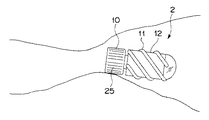
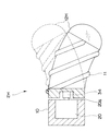
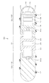
図2及び図3に示すようにカプセル本体2は、ベース部10と、このベース部10に連結され、外表面に螺旋状突起11を設けた螺旋回転推進部12とを有して構成されている。
前記螺旋状突起11は、前記螺旋回転推進部12の外表面に丸みを設けた略半球状等の断面構造にして、体内の内壁面に滑らかに接触するようになっている。
As shown in FIGS. 2 and 3, the
The
前記螺旋回転推進部12は、一方の端部(前端という)に半球状の透明部材13が形成され、その中央付近には透明部材13に対向してCCD( Charge Coupled Device )等の撮像装置14が配置され、その周囲の例えば4箇所にはLED( Light Emitting Diode )等の照明装置15が配置されている。
前記撮像装置14及び前記照明装置15の後方側には、第1バッテリ16と、画像送信ユニット17と、制御回路18とが設けられている。
The spiral
A
前記第1バッテリ16は、前記螺旋回転推進部12内部の各部に電源電力を供給するようになっている。前記画像送信ユニット17は、前記撮像装置14からの撮像信号を信号処理して得た画像信号を変調等送信処理を施して図示しないカプセル側アンテナより前記体外装置3へ送信するようになっている。尚、前記画像送信ユニット17は、カプセル側アンテナを内蔵してもよいし、また別体に設けてもよい。
前記制御回路18は、前記撮像装置14及び前記照明装置15の制御を行うようになっている。
The
The
一方、前記ベース部10には、前記螺旋回転推進部12を回転させるための回転手段である第1モータ20が配置されている。尚、ここで、ベース部10とは、前記螺旋回転推進部12を回転させるためのモータを備えていると定義する。
On the other hand, the
前記第1モータ20のモータ軸20aは、前記螺旋回転推進部12の後端部に嵌合固定され、前記螺旋回転推進部12を前記ベース部10に対して相対的に回転させるようになっている。
このことにより、前記螺旋回転推進部12は、前記第1モータ20の回転力により前記ベース部10に対し相対的に回転し、この回転を前記螺旋状突起11が推力(推進力)に変換して螺旋軸方向(螺旋軸21の方向)に推進力を発生することができる。
A
As a result, the helical
また、前記ベース部10には、前記螺旋回転推進部12の前記螺旋状突起11を生体に接触させるための第2モータ22が配置されている。この第2モータ22には、揺動手段(振動手段)として揺動(振動)を発生するように偏心ロータ23を設けている。
The
前記第2モータ22の駆動により、カプセル本体2は、前記偏心ロータ23から振動が発生し、この振動がベース部10から前記螺旋回転推進部12に伝達されてカプセル全体を揺動(振動)させるようになっている。
このことにより、カプセル本体2は、前記螺旋状突起11が体腔内壁に接触せず推進ができない場合でも、カプセル全体の揺動(振動)によりそこで停止することなく螺旋状突起11が体腔に接触するような状態に遷移し、推進し続けることができるようになっている。尚、前記第1モータ20,第2モータ22は、前記ベース部10に設けた第2バッテリ24から電源電力を供給されるようになっている。
By driving the
As a result, even when the
また、前記ベース部10には、このベース部10が回転しないように回転防止手段として外表面に長手軸と平行に複数の溝部25が形成されている。
このことにより、前記カプセル本体2は、推進を妨げずに前記ベース部10が体腔内壁に対し回転するのを防止するようになっている。
In addition, a plurality of
Thus, the
このような構成による本実施例の作用を説明する。
カプセル本体2により体腔内を検査する場合、患者はこのカプセル本体2を飲み込む。体腔内に飲みこまれたカプセル本体2は食道等を通過する際に、照明装置15で照明し、撮像装置14で体腔内の画像を撮像する。
The operation of the present embodiment having such a configuration will be described.
When examining the inside of a body cavity with the
カプセル本体2は、撮像装置14からの撮像信号を画像送信ユニット17により信号処理して得た画像信号を変調等送信処理を施してカプセル側アンテナから体外装置3に電波で送信する。
The
体外装置3は、体外アンテナ3aにより受信した電波を復調し、この復調した画像データを信号処理して画像データを得る。そして、体外装置3は、カプセル本体2により順次撮像された画像データをモニタ3bの表示画面にカプセル画像として表示する。
The
ここで、カプセル本体2は、前記第2バッテリ24からの電源電力を供給されて前記第1モータ20が駆動し、この第1モータ20のモータ軸20aに嵌合された前記螺旋回転推進部12が回転する。
Here, the
前記螺旋回転推進部12は、前記第1モータ20のモータ軸20aから回転力を伝達され、この第1モータ20の回転力により前記ベース部10に対し相対的に回転する。尚、このとき、前記ベース部10は、前記回転防止手段である前記外表面に形成した溝部25により推進を妨げずに前記体腔内壁に対して回転するのを防止している。
The helical
この螺旋回転推進部12の回転によって、カプセル本体2は、螺旋回転推進部12の螺旋状突起11と体腔内壁との接触部分に雄ねじが雌ねじに対して移動するような、螺旋回転推進部12を前進させる推進力が発生する。
By the rotation of the helical
これにより、カプセル本体2は、前記螺旋回転推進部12が螺旋軸方向(螺旋軸21の方向)に推進力を発生し、前進することができる。
従って、カプセル本体2は、良好に螺旋回転推進部12が機能して体腔内への推進力を得ることができる。
Thereby, the capsule
Therefore, the
ここで、例えば、カプセル本体2は、図4に示すように体腔内管路が狭まった部分を通過したところとする。狭まった先は、空間が広くあいている。
すると、カプセル本体2は、図4に示すように前記螺旋回転推進部12が体腔内管路の内壁に接触しなくなり、先に進まなくなってしまう。
Here, for example, it is assumed that the capsule
Then, as shown in FIG. 4, in the
このとき、図5に示すようにカプセル本体2の前記第2モータ22を駆動する。
この第2モータ22の駆動により、カプセル本体2は、前記偏心ロータ23から振動が発生し、この振動がベース部10から前記螺旋回転推進部12に伝達されてカプセル全体を揺動(振動)させる。
At this time, the
By driving the
すると、カプセル本体2は、図6に示すように上記揺動(振動)により体腔内管路の狭まった部分から脱出でき、前記螺旋回転推進部12が体腔内壁と接触する状態に戻って前記螺旋回転推進部12の回転により推進し続ける。
Then, as shown in FIG. 6, the
これにより、カプセル本体2は、前記螺旋状突起11が体腔内壁に接触せず推進ができない場合でも、カプセル全体の揺動(振動)によりそこで停止することなく螺旋状突起11が体腔内壁に接触するような状態に遷移し、推進し続けることができる。
この結果、本実施例のカプセル型医療システム1は、良好に螺旋回転推進部12が機能して体腔内への推進力を得ることができる。
As a result, even when the capsule
As a result, in the capsule
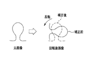
尚、前記カプセル本体2は、前記撮像装置14が前記螺旋回転推進部12に設けられているので、得られるカプセル画像が回転してしまう。
そこで、前記第1モータ20に角度検出手段を設け、この角度検出手段により検出された角度情報に基づき、カプセル画像を角度補正してもよい。あるいは、角度検出手段を設け、その情報の積分値に基づき、角度を求めてもよい。
In the
Therefore, angle detection means may be provided in the
図7に示すようにカプセル本体2Bは、前記第1モータ20に角度検出センサ26を設けて構成されている。
この場合、前記画像送信ユニット17は、前記撮像装置14からの前記撮像信号に対して前記角度検出センサ26からの角度情報を関係付けて前記体外装置3へ送信するようになっている。
As shown in FIG. 7, the
In this case, the
そして、前記体外装置3は、図8に示すように前記カプセル本体2から受信した前記角度情報に基づき、前記画像信号に対して角度補正処理を行うようになっている。
尚、上記角度補正処理は、前記画像送信ユニット17により行うように構成してもよい。この場合、前記画像送信ユニット17は、前記角度検出センサ26からの角度情報に基づき、前記撮像装置14からの撮像信号に対して角度補正処理を行って得た画像信号を体外装置3へ送信するようにしてもよい。
これにより、カプセル本体2Bは、回転しないカプセル画像を得ることができる。
The
The angle correction process may be performed by the
Accordingly, the capsule body 2B can obtain a capsule image that does not rotate.
また、カプセル本体は、前記第2モータ22を用いることなく、図9に示すように形状記憶合金を用いて前記螺旋接触手段である前記揺動手段(振動手段)を構成してもよい。
図9に示すようにカプセル本体2Cは、揺動手段(振動手段)として前記螺旋回転推進部12にSMA( Shape Memory Alloy )を用いている。
Further, the capsule body may constitute the swing means (vibration means) which is the spiral contact means using a shape memory alloy as shown in FIG. 9 without using the
As shown in FIG. 9, the capsule body 2C uses SMA (Shape Memory Alloy) for the spiral
更に具体的に説明すると、前記カプセル本体2Cは、前記螺旋回転推進部12の外周付近に錘27aが移動可能な空間部27bを形成している。この空間部27bには、前記錘27aの両端にSMAワイヤにより形成されたSMAコイル28を接続している。前記SMAコイル28は、通電により伸縮して前記錘を往復運動させるようになっている。
More specifically, the capsule body 2C forms a space 27b in which the weight 27a can move near the outer periphery of the spiral
また、前記螺旋回転推進部12には、前記SMAコイル28に通電するSMA駆動回路29が設けられている。
前記カプセル本体2Cは、前記SMA駆動回路29からの信号により先端又は後端側のSMAコイル28が伸縮することで錘27aが往復運動してカプセル全体の重心が変化するようになっている。
The spiral
The capsule body 2C is configured such that the weight 27a is reciprocated by the expansion and contraction of the
これにより、前記カプセル本体2Cは、連続的にカプセル全体の重心を変化させることで、カプセル全体に上記実施例1で説明したのと同様、あるいはより大きな揺動(振動)を発生することができる。尚、前記カプセル本体2Cは、SMAコイル28の代わりに導電性ポリマー(人工筋肉)やリニアアクチュエータなどを用いて構成してもよい。
As a result, the capsule body 2C can change the center of gravity of the entire capsule continuously to generate the same oscillation or greater vibration (vibration) in the entire capsule as described in the first embodiment. . The capsule body 2C may be configured using a conductive polymer (artificial muscle), a linear actuator, or the like instead of the
また、カプセル本体は、前記ベース部10に対して前記螺旋回転推進部12が首振りするように前記螺旋接触手段を構成してもよい。
図10に示すようにカプセル本体2Dは、前記ベース部10を2つに分割し、それぞれに回転用モータを設けて構成されている。
The capsule main body may constitute the spiral contact means so that the spiral
As shown in FIG. 10, the
更に具体的に説明すると、前記カプセル本体2Dは前記螺旋回転推進部12を回転させる前記第1モータ20が傾斜ベース部材30に嵌合固定されてこの傾斜ベース部材30に傾くように取り付けられている。
前記傾斜ベース部材30は、後端部に前記第2モータ22のモータ軸22aが嵌合固定されており、この第2モータ22の駆動により前記螺旋回転推進部12ごと回転されるようになっている。尚、前記第2モータ22は、ベース部本体10aに配置されている。
More specifically, the
The
これにより、カプセル本体2Dは、前記螺旋回転推進部12の回転軸31と、傾斜ベース部材30の中心軸32とが傾いているので、図11に示すように前記螺旋回転推進部12が前記ベース部10に対して首を振るようにしながら回転する。
従って、カプセル本体2Dは、上記実施例1と同様な効果を得ることに加え、前記螺旋回転推進部12が前記ベース部10に対し常に移動しているので、体腔内壁に接触する機会が増え、より推進し易くなる。
Thereby, since the
Therefore, in addition to obtaining the same effect as the first embodiment, the
また、カプセル本体は、前記ベース部10に対して前記螺旋回転推進部12が偏心するように前記螺旋接触手段を構成してもよい。
図12に示すようにカプセル本体2Eは、前記螺旋回転推進部12の回転軸31と前記傾斜ベース部材30の中心軸32とがオフセットするように、前記螺旋回転推進部12の後端部に前記第1モータ20のモータ軸20aが嵌合固定されている。
Further, the capsule body may constitute the spiral contact means so that the spiral
As shown in FIG. 12, the capsule main body 2E is disposed at the rear end of the spiral
これにより、カプセル本体2Eは、前記螺旋回転推進部12が前記ベース部10に対し偏心するので、図13に示すように前記螺旋回転推進部12が前記ベース部10に対して常に移動することになる。
従って、カプセル本体2Eは、前記カプセル本体2Dと同様な効果を得る。
As a result, the capsule body 2E has the spiral
Therefore, the capsule body 2E obtains the same effect as the
また、カプセル本体は、前記カプセル本体2Dと同様に前記ベース部10を2つに分割してそれぞれに回転用モータを設け、更に前記カプセル本体2Eと同様に前記螺旋回転推進部12が偏心するように前記螺旋接触手段を構成してもよい。
図14に示すようにカプセル本体2Fは、前記螺旋回転推進部12を回転させる前記第1モータ20がベース部材33に嵌合固定されて取り付けられている。このベース部材33は、前記傾斜ベース部材30の中心軸32が前記螺旋回転推進部12の回転軸31とオフセットするように、後端部に前記第2モータ22のモータ軸22aが嵌合固定されて取り付けられ、この第2モータ22の駆動により前記螺旋回転推進部12ごと回転されるようになっている。尚、前記第2モータ22は、ベース部本体10aに配置されている。
Also, the capsule body is divided into two
As shown in FIG. 14, the
これにより、カプセル本体2Fは、前記螺旋回転推進部12が前記ベース部10に対し偏心するので、図15に示すように前記螺旋回転推進部12が自身の回転軸31を軸にして回転しながら、前記ベース部10に対し常に移動することになる。
従って、カプセル本体2Fは、前記カプセル本体2Eと同様な効果を得る。
As a result, the
Therefore, the
また、カプセル本体は、前記螺旋回転推進部12が屈曲するように前記螺旋接触手段を構成してもよい。
図16に示すようにカプセル本体2Gは、前記第1モータ20と前記螺旋回転推進部12とを可撓性を有するフレキシブルシャフト34で連結し、前記螺旋回転推進部12が屈曲するように構成されている。即ち、前記フレキシブルシャフト34は、屈曲手段を構成している。
The capsule body may constitute the spiral contact means so that the spiral
As shown in FIG. 16, the
これにより、カプセル本体2Gは、図17に示すように前記螺旋回転推進部12が外部からの力で前記ベース部10に対し回転しながら自由に傾くことができる。
従って、カプセル本体2Gは、図18に示すように体腔内の屈曲部に達した際、図19に示すように前記螺旋回転推進部12と体腔内壁とが接触すると前記螺旋回転推進部12が推進する方向の下側に向きを変え、屈曲部を通過し易くなる。
更に、回転による遠心力で螺旋回転推進部12が首をふるように回転するため、カプセル本体2Gは、前記カプセル本体2Eと同様な効果を得る。
Thereby, as shown in FIG. 17, the capsule
Accordingly, when the
Furthermore, since the helical
また、カプセル本体は、前記螺旋回転推進部12が屈曲するように前記屈曲手段を構成してもよい。
図20に示すようにカプセル本体2Hは、前記屈曲手段として螺旋回転推進部12Hが外部からの力で変形する弾性体により形成されている。
これにより、カプセル本体2Hは、前記カプセル本体2Gと同様な効果を得る。
The capsule body may constitute the bending means so that the spiral
As shown in FIG. 20, the capsule main body 2H is formed of an elastic body in which the helical
Thereby, the capsule body 2H obtains the same effect as the
尚、本実施例は、体腔内を撮像するカプセル型内視鏡として機能するカプセル本体に本発明を適用して構成しているが、本発明はこれに限定されず、生体組織を採取する採取手段を有する組織採取型カプセル型医療装置、薬剤を放出する薬剤放出型カプセル型医療装置、生体組織を焼灼する焼治療型カプセル型医療装置に本発明を適用しても構わない。 In this embodiment, the present invention is applied to a capsule body that functions as a capsule endoscope that images the inside of a body cavity. However, the present invention is not limited to this, and sampling for collecting biological tissue is performed. The present invention may be applied to a tissue-collecting capsule medical device having a means, a drug-releasing capsule medical device that releases a drug, and an ablation type capsule medical device that cauterizes a living tissue.
図21ないし図31は本発明の実施例2に係わり、図21は実施例2のカプセル本体を示す外観説明図、図22は図21のカプセル本体の内部構成を示す説明図、図23は電気刺激を与えるように螺旋接触手段を構成したカプセル本体の内部構成を示す説明図、図24は体腔内を吸引する吸引機構を設けて螺旋接触手段を構成したカプセル本体の内部構成を示す説明図、図25は図24の第1モータ,第2モータの要部説明図、図26は送気機構を設けて螺旋回転推進部の外径を変化させる径可変手段により螺旋接触手段を構成したカプセル本体の内部構成を示す説明図、図27はバルーンにより螺旋状突起を形成して径可変手段を構成したカプセル本体の外観図、図28は回転防止手段としてキャタピラを設けたベース部の説明図、図29は回転防止手段としてローラ状タイヤを設けたベース部の説明図、図30は回転防止手段としてフィン状突起を設けたベース部の説明図、図31は回転防止手段としてブラシを設けたベース部の説明図である。 FIGS. 21 to 31 relate to the second embodiment of the present invention, FIG. 21 is an external explanatory view showing the capsule body of the second embodiment, FIG. 22 is an explanatory view showing the internal configuration of the capsule body of FIG. 21, and FIG. FIG. 24 is an explanatory view showing the internal configuration of the capsule body that configures the spiral contact means so as to give a stimulus; FIG. 24 is an explanatory view showing the internal configuration of the capsule body that configures the spiral contact means by providing a suction mechanism that sucks the inside of the body cavity; FIG. 25 is an explanatory view of the main parts of the first motor and the second motor of FIG. 24, and FIG. FIG. 27 is an external view of a capsule body in which a spiral protrusion is formed by a balloon to form a diameter variable means, and FIG. 28 is an explanatory view of a base portion provided with a caterpillar as a rotation preventing means. 29 FIG. 30 is an explanatory view of a base portion provided with fin-like protrusions as rotation preventing means, and FIG. 31 is an explanatory view of a base portion provided with brushes as rotation preventing means. FIG.
上記実施例1は螺旋回転推進部12を1つ設けてベース部10と連結して構成しているが、実施例2は前記ベース部10を中心に前記螺旋回転推進部12を2つ設けて構成する。それ以外の構成は上記実施例1とほぼ同様なので、同じ構成には同じ符号を付して説明を省略する。
In the first embodiment, one spiral
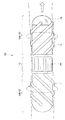
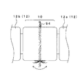
図21及び図22に示すように、実施例2のカプセル本体50は、ベース部10を中心に前記螺旋回転推進部12を2つ設けて構成されている。
更に具体的に説明すると、前記カプセル本体50は、ベース部10と、このベース部10に取り付けられた第1モータ20,第2モータ22により前記ベース部10に対して相対的に回転する前方側螺旋回転推進部12a及び後方側螺旋回転推進部12bとを有して構成されている。これら前方側螺旋回転推進部12aと後方側螺旋回転推進部12bとは、外表面に設けられる前記螺旋状突起11が互いに逆向きとなるように形成されている。尚、前方とは、撮像装置14の向いている方向と定義する。
As shown in FIGS. 21 and 22, the capsule
More specifically, the
前記ベース部10には、前記前方側螺旋回転推進部12aを回転させる第1モータ20と、前記後方側螺旋回転推進部12bを回転させる第2モータ22と、これら第1モータ20,第2モータ22を駆動するための電源電力を供給する第2バッテリ24が設けられている。
これにより、前記カプセル本体50は、一方の螺旋回転推進部12(前方側螺旋回転推進部12a又は後方側螺旋回転推進部12b)が体腔内壁に接触せずに推進できない場合でも、他方の螺旋回転推進部12(後方側螺旋回転推進部12b又は前方側螺旋回転推進部12a)が体腔内壁に接触するよう補助して推進し続けることができる。
The
Thereby, even if one capsule rotation propulsion unit 12 (the front side spiral
尚、カプセル本体は、電気刺激を与えるように前記螺旋接触手段を構成してもよい。
図23に示すようにカプセル本体50Bは、電気刺激を与えることにより体腔内管路である腸管の収縮により前記螺旋回転推進部12が常に腸管内壁に接触する状態を維持するように構成されている。
The capsule body may constitute the spiral contact means so as to apply electrical stimulation.
As shown in FIG. 23, the capsule
更に具体的に説明すると、カプセル本体50Bは、螺旋状突起11に図示しない電極を形成してこの電極に電気刺激として電気信号を出力する電気刺激制御回路61と、この電気刺激制御回路61を駆動するための電源電力を供給する第3バッテリ62と有して構成されている。尚、前記螺旋状突起11は、一端が前記電気刺激制御回路61に電気的に接続され、他端が図示しないスリップリングを介して前記電気刺激制御回路61に電気的に接続されて閉回路を構成している。
More specifically, the
これにより、カプセル本体50Bは、体腔内管路である腸管に対して螺旋状突起11から電気刺激を与えることにより、腸管が収縮して前記ベース部10及び前記螺旋回転推進部12(前方側螺旋回転推進部12a又は後方側螺旋回転推進部12b)とが常に腸管内壁と接触状態を保ち安定的に推進する。
As a result, the
また、カプセル本体は、体腔内を吸引する吸引機構を設けて前記螺旋接触手段を構成してもよい。
図24に示すようにカプセル本体50Cは、吸引機構により体腔内管路である腸管内を吸出して前記螺旋回転推進部12が常に腸管内壁に接触する状態を維持するように構成されている。
Further, the capsule body may be provided with a suction mechanism for sucking the inside of the body cavity to constitute the spiral contact means.
As shown in FIG. 24, the capsule body 50C is configured to suck the inside of the intestinal tract, which is an intracorporeal duct, by a suction mechanism so that the spiral
更に具体的に説明すると、カプセル本体50Cは、腸管内の空気や体液等の流体を吸引するための吸引装置63と、この吸引装置63に接続されて流体を吸引する吸引管路64と、吸引した流体を排出するための排出管路65とを有して構成されている。
More specifically, the capsule body 50C includes a
前記吸引装置63は、前記後方側螺旋回転推進部12bに配置されている。このため、前記前方側螺旋回転推進部12aは、前記ベース部10を介して前記吸引管路64が前記吸引装置63に接続されている。
The
前記吸引管路64は、前記第1モータ20,第2モータ22を介して接続されている。
図25に示すように前記第1モータ20,第2モータ22は、モータ内部空間において、貫通路71aが形成された回転軸71がOリング72によって気密に構成され、吸引管路64を構成している。尚、モータ20,22は、ロータ71bとステータ71cとから構成されている。
The
As shown in FIG. 25, in the
これにより、カプセル本体50Cは、体腔内管路である腸管に対して空気や体液等の流体を吸出しすることにより、前記カプセル本体50Bと同様に腸管が収縮して前記ベース部10及び前記螺旋回転推進部12とが常に腸管内壁と接触状態を保ち安定的に推進する。
As a result, the capsule body 50C sucks fluid such as air or body fluid into the intestinal tract which is a body cavity duct, so that the intestinal tract contracts in the same manner as the
また、カプセル本体は、送気機構を設けて前記螺旋回転推進部12の外径を変化させる径可変手段により前記螺旋接触手段を構成してもよい。
図26に示すようにカプセル本体50Dは、送気機構により前記螺旋回転推進部12及び前記ベース部10が膨張して常に腸管内壁に接触する状態を維持するように構成されている。
Further, the capsule main body may constitute the spiral contact means by a diameter variable means for providing an air supply mechanism to change the outer diameter of the spiral
As shown in FIG. 26, the capsule main body 50D is configured so that the spiral
更に具体的に説明すると、カプセル本体50Dは、腸管内の空気や体液等の流体を取り込む吸引管路80と、この吸引管路80に接続され、取り込んだ流体を送気する送気装置81と、前記ベース部10及び前記螺旋回転推進部12に設けたバルーン82と、このバルーン82に前記送気装置81からの流体を送気するための送気管路83とを有して構成されている。即ち、前記バルーン82は、前記径可変手段を構成している。
More specifically, the capsule body 50D includes a
尚、前記ベース部10に設けたベース側バルーン82aには、回転防止手段として外表面に長手軸と平行に複数の溝部25が形成されている。一方、前記螺旋回転推進部12に設けた螺旋側バルーン82bには、螺旋状突起11が設けられている。
A plurality of
前記送気装置81は、前記後方側螺旋回転推進部12bに配置されている。このため、前記ベース部10及び前記前方側螺旋回転推進部12aに設けられたバルーン82には、前記カプセル本体50Bと同様に、前記第1モータ20,第2モータ22が送気管路83の一部を形成して前記送気装置81に接続されている。
The air supply device 81 is disposed in the rear spiral
これにより、カプセル本体50Dは、体腔内管路である腸管に対して空気や体液等の流体を取り込んで前記バルーン82(ベース側バルーン82a,螺旋側バルーン82b)に送気することにより、バルーン82が膨張して前記ベース部10及び前記螺旋回転推進部12とが常に腸管内壁と接触状態を保ち安定的に推進する。
As a result, the capsule body 50D takes in fluid such as air or body fluid into the intestinal tract that is a body cavity duct, and supplies the fluid to the balloon 82 (
また、カプセル本体は、バルーンにより螺旋状突起を形成して径可変手段を構成してももよい。
図27に示すようにカプセル本体50Eは、バルーンにより螺旋状突起を形成した螺旋状バルーン84を設けて構成されている。即ち、この螺旋状バルーン84は、径可変手段を構成している。尚、図示しないが、前記カプセル本体50Eは送気管路83が前記螺旋状バルーン84に接続されている。
Further, the capsule body may form a diameter variable means by forming a spiral projection with a balloon.
As shown in FIG. 27, the
これにより、カプセル本体50Eは、体腔内管路である腸管に対して空気や体液等の流体を取り込んで前記ベース部10のバルーン82及び螺旋状バルーン84に送気することにより、これらバルーンが膨張して前記ベース部10及び前記螺旋回転推進部12とが常に腸管内壁と接触状態を保ち安定的に推進する。
As a result, the
尚、ベース部10は、前記回転防止手段として図28〜図31に示すように構成してもよい。
図28に示すようにベース部10は、前記回転防止手段としてキャタピラ90を設けている。前記キャタピラ90は、複数個のローラ状タイヤ91(図中では3つ)が図示しない支点を中心に回転可能に設けて、これらローラ状タイヤ91にベルト92を架けて構成されている。尚、前記キャタピラ90は、複数個(図中、紙面に対して上下前後方向に4つ)設けられている。
The
As shown in FIG. 28, the
また、図29に示すようにベース部10には、前記回転防止手段としてローラ状タイヤ91のみを複数個設けている。また、図30に示すようにベース部10には、前記回転防止手段としてフイン状突起93を複数個設けている。また、図31に示すようにベース部10には、前記回転防止手段としてブラシ94を周状に設けている。
上記図28〜図31に示すように構成した回転防止手段により、カプセル本体50は、前記螺旋回転推進部12の推進を妨げずに、前記ベース部10が体腔に対し回転するのを防止する。
Further, as shown in FIG. 29, the
With the rotation preventing means configured as shown in FIGS. 28 to 31, the
図32及び図33は本発明の実施例3に係わり、図32は実施例3のカプセル本体を示す外観説明図、図33は螺旋回転推進部をシース状に形成して撮像装置をベース部に設けたカプセル本体の内部構成を示す説明図である。 32 and 33 relate to the third embodiment of the present invention, FIG. 32 is an external explanatory view showing the capsule main body of the third embodiment, and FIG. 33 is a spiral rotation propulsion portion formed in a sheath shape and the imaging device is used as a base portion. It is explanatory drawing which shows the internal structure of the provided capsule main body.
上記実施例1,2は螺旋回転推進部12に撮像装置14が設けられ、撮像されるカプセル画像が回転するように構成しているが、実施例3は撮像されるカプセル画像が回転しないように構成する。それ以外の構成は上記実施例1,2とほぼ同様なので、同じ構成には同じ符号を付して説明を省略する。
In the first and second embodiments, the
図32に示すように、実施例3のカプセル本体100は、撮像されるカプセル画像が回転しないように撮像装置14を前記ベース部10に設けて構成されている。
更に具体的に説明すると、カプセル本体100は、ベース部10の端部(前端という)に半球状の透明部材13が形成され、その中央付近には透明部材13に対向して撮像装置14が配置され、その周囲の例えば4箇所にはLED等の照明装置15が配置されている。
As shown in FIG. 32, the
More specifically, in the
尚、前記螺旋回転推進部12には、図示しないが上記実施例1と同様に前記第1バッテリ16と、前記画像送信ユニット17と、前記制御回路18が設けられており、図示しないスリップリングを介して前記撮像装置14及び前記照明装置15が電気的に接続されて駆動するようになっている。それ以外の構成は、上記実施例1と同様なので、説明を省略する。
これにより、前記カプセル本体100は、撮像されるカプセル画像が回転しないので、画像処理する必要がなく簡易な構成でカプセル画像を得られる。
Although not shown, the spiral
Thereby, since the
また、カプセル本体は、撮像されるカプセル画像が回転しないように、螺旋回転推進部12をシース状に形成して撮像装置14を前記ベース部10に設けてもよい。
図33に示すようにカプセル本体100Bは、シース状に形成したシース状螺旋回転推進部101がベース部10Bを覆うように構成されている。
Moreover, the capsule main body may be provided with the
As shown in FIG. 33, the capsule body 100B is configured such that a sheath-like spiral
前記シース状螺旋回転推進部101は、前記ベース部10Bに対してベアリング部102により回転可能に構成されている。また、前記ベース部10Bに設けられた第1モータ20のモータ軸20aには、ピニオン21bに前記シース状螺旋回転推進部101が噛合している。
The sheath-like spiral
これにより、前記シース状螺旋回転推進部101は、前記第1モータ20の駆動により前記ベース部10Bを覆うように回転するようになっている。即ち、前記シース状螺旋回転推進部101は、シース状の回転体である。
Thereby, the sheath-like spiral
前記ベース部10Bは、端部(前端という)に半球状の透明部材13が形成され、その中央付近には透明部材13に対向して撮像装置14が配置され、その周囲の例えば4箇所にはLED等の照明装置15が配置されている。前記撮像装置14及び前記照明装置15の後方側には、前記第1バッテリ16と、前記画像送信ユニット17と、前記制御回路18とが設けられている。
これにより、前記カプセル本体100Bは、撮像されるカプセル画像が回転しないので、上記カプセル本体100と同様な効果を得る。
The base portion 10B is formed with a hemispherical
Thereby, since the capsule body 100B does not rotate the captured capsule image, the capsule body 100B obtains the same effect as the
図34ないし図36は本発明の実施例4に係わり、図34は実施例4のカプセル本体を示す外観説明図、図35は図34のカプセル本体の内部構成を示す説明図、図36はベース部の長手軸と螺旋回転推進部の長手軸とが屈曲するように螺旋接触手段を構成したカプセル本体の内部構成を示す説明図である。 FIGS. 34 to 36 relate to the fourth embodiment of the present invention, FIG. 34 is an external explanatory view showing the capsule body of the fourth embodiment, FIG. 35 is an explanatory view showing the internal configuration of the capsule body of FIG. 34, and FIG. It is explanatory drawing which shows the internal structure of the capsule main body which comprised the helical contact means so that the longitudinal axis of a part and the longitudinal axis of a helical rotation promotion part might be bent.
上記実施例1〜3は回転防止手段としてベース部の外表面に長手軸と平行に複数の溝部25が形成されているが、実施例4はベース部の外表面に螺旋状突起11を設けて構成する。それ以外の構成は上記実施例1,2とほぼ同様なので、同じ構成には同じ符号を付して説明を省略する。
In the first to third embodiments, a plurality of
図34及び図35に示すように、実施例4のカプセル本体110は、前記螺旋回転推進部12を回転させるための前記第1モータ20を備えているベース部111の外表面に螺旋状突起11を設けて構成されている。
前記ベース部111は、前記第1モータ20の駆動による前記螺旋回転推進部12の回転に対して慣性力により前記螺旋回転推進部12に対して逆回転するようになっている。
As shown in FIGS. 34 and 35, the
The
これにより、カプセル本体110は、前記ベース部111の逆回転によって、体腔内壁に対しカプセル全体が回転することを防止するようになっている。
また、カプセル本体110は、前記第1モータ20に角速度センサ112が設けられている。前記角速度センサ112は、前記螺旋回転推進部12が空転すると負荷がなくなり回転速度が変化することを検知するようになっている。これにより、螺旋回転推進部12の回転速度の最適化を行い、効率的な推進を実現できる。
Thereby, the capsule
In addition, the
尚、前記カプセル本体110は、図示しないが上記実施例1で説明した前記カプセル本体2と同様な前記偏心ロータ23を設けた第2モータ22又は、前記カプセル本体2Cと同様なSMAコイル28を設けた振動手段(揺動手段)、或いは前記カプセル本体50Bと同様な電気刺激を与えて腸管の収縮を行う等、前記螺旋接触手段を設けて構成している。これにより、カプセル本体110は、螺旋回転推進部12と体腔内壁との接触状態を回復し推進させることができる。
Although not shown, the
尚、カプセル本体は、ベース部の長手軸と螺旋回転推進部の長手軸とが屈曲するように前記螺旋接触手段を構成してもよい。
図36に示すようにカプセル本体110Bは、ベース部111Bの長手軸113と螺旋回転推進部12Bの長手軸114とが屈曲する状態を維持するように構成されている。
Note that the capsule body may constitute the spiral contact means such that the longitudinal axis of the base portion and the longitudinal axis of the spiral rotation propulsion portion are bent.
As shown in FIG. 36, the
更に具体的に説明すると、カプセル本体110Bは、前記ベース部111Bと前記螺旋回転推進部12Bとがくの字型を形成するように前記第1モータ20によって連結されている。
これにより、前記カプセル本体110Bは、ベース部111Bの長手軸113と螺旋回転推進部12Bの長手軸114とが屈曲した状態で回転することにより、体腔内壁に対して常に良好な接触状態を維持することができる。
More specifically, the
Accordingly, the
図37ないし図40は本発明の実施例5に係わり、図37は実施例5のカプセル本体を示す外観説明図、図38は図37のカプセル本体の内部構成を示す説明図、図39は図37のカプセル本体が体腔内管路の屈曲部を通過する直前の様子を示す説明図、図40は図39の状態から体腔内管路の屈曲部を通過している際のカプセル本体の様子を示す説明図である。 FIGS. 37 to 40 relate to the fifth embodiment of the present invention, FIG. 37 is an external explanatory view showing the capsule body of the fifth embodiment, FIG. 38 is an explanatory view showing the internal configuration of the capsule body of FIG. 37, and FIG. FIG. 40 is an explanatory view showing a state immediately before the capsule body 37 passes through the bent part of the body cavity duct, and FIG. 40 shows the state of the capsule body when passing through the bent part of the body cavity pipe from the state of FIG. It is explanatory drawing shown.
上記実施例2はベース部10が外形を変更しないように構成しているが、実施例5はベース部が関節を有して屈曲するように構成する。それ以外の構成は上記実施例2とほぼ同様なので、同じ構成には同じ符号を付して説明を省略する。
In the second embodiment, the
図37及び図38に示すように、実施例5のカプセル本体120は、ベース部121を中心に前記螺旋回転推進部12を2つ設けて構成されている。
更に具体的に説明すると、前記カプセル本体50は、ベース部121と、このベース部121に取り付けられた第1モータ20,第2モータ22により前記ベース部121に対して相対的に回転する前方側螺旋回転推進部12a及び後方側螺旋回転推進部12bとを有して構成されている。前記前方側螺旋回転推進部12aと前記後方側螺旋回転推進部12bとは、これら外表面に設けられる前記螺旋状突起11が互いに逆向きとなるように形成されている。
As shown in FIGS. 37 and 38, the
More specifically, the
前記ベース部121は、前方側関節122aと後方側関節122bとを有し、これら関節122a,122bの軸部123a,123bをボールジョイント124により連結すると共に、屈曲するよう前記軸部123a,123bの周囲を屈曲手段として例えば、4本のSMAコイル125により接続している。更に、前記ベース部121は、前記前方側関節122aと前記後方側関節122bとの間を蛇腹129により覆っている。
The
尚、前記ベース部121は、前記ボールジョイント124の代わりに図示しないフレキシブルシャフトを用いて構成してもよい。
前記前方側関節122aには、前記前方側螺旋回転推進部12aを回転させる第1モータ20が配置され、この第1モータ20を駆動するための電源電力を供給する第2バッテリ24が設けられている。
The base 121 may be configured using a flexible shaft (not shown) instead of the ball joint 124.
A
一方、前記後方側関節122bには、前記後方側螺旋回転推進部12bを回転させるための第2モータ22が配置されると共に、前記SMAコイル125に通電するSMA駆動回路131が配置され、これら第2モータ22及びSMA駆動回路131を駆動するための電源電力を供給する第3バッテリ132が設けられている。
On the other hand, the rear joint 122b is provided with a
これにより、前記カプセル本体120は、前記SMA駆動回路131から通電することで、前記4本のSMAコイル125が伸縮し、ベース部121が任意の方向に屈曲可能となっている。尚、図中、カプセル本体120は、上側のSMAコイル125が伸びると共に、下側のSMAコイル125が縮んで前記ベース部121が下側向きに屈曲して前記前方側螺旋回転推進部12aが下側を向いている状態となっている。
Accordingly, when the
即ち、前記関節122a,122b及び前記屈曲手段であるSMAコイル125は、推進方向変更手段を構成している。
従って、カプセル本体120は、図39に示すように体腔内の屈曲部に達した際、図40に示すように前記ベース部121が屈曲することにより、前記前方側螺旋回転推進部12aが推進する方向の下側に向きを変え、屈曲部を通過し易くなる。
That is, the joints 122a and 122b and the
Therefore, when the
尚、本発明は、以上述べた実施例のみに限定されるものではなく、発明の要旨を逸脱しない範囲で種々変形実施可能である。 The present invention is not limited to the above-described embodiments, and various modifications can be made without departing from the spirit of the invention.
[付記]
(付記項1)
生体内に送り込まれ、この生体内を推進するカプセル型医療装置本体であって、
ベース部と、
前記ベース部に連結され、外表面に螺旋状突起を設けた螺旋回転推進部と、
前記ベース部に対し前記螺旋回転推進部を相対的に回転させる回転手段と、
を具備し、
前記螺旋状突起を設けた前記螺旋回転推進部が、前記回転手段によって回転されることにより螺旋軸方向に推進力を発生することを特徴とするカプセル型医療装置本体。
[Appendix]
(Additional item 1)
A capsule-type medical device body that is sent into a living body and promotes the living body,
A base part;
A spiral rotation propulsion unit connected to the base unit and provided with a spiral projection on the outer surface;
A rotating means for rotating the helical rotation propulsion unit relative to the base unit;
Comprising
The capsule medical device main body characterized in that the helical rotation propulsion unit provided with the helical protrusion generates a propulsive force in the direction of the helical axis by being rotated by the rotating means.
(付記項2)
前記ベース部を中心に前記螺旋回転推進部を2つ設け、これら2つの螺旋回転推進部に設けられた前記螺旋状突起が互いに逆向きであることを特徴とする付記項1に記載のカプセル型医療装置本体。
(付記項3)
前記ベース部は、略円筒形状に形成され、生体に対して回転することを防止する回転防止手段を備えていることを特徴とする付記項1又は2に記載のカプセル型医療装置本体。
(Appendix 2)
The capsule mold according to
(Additional Item 3)
The capsule medical device main body according to
(付記項4)
前記ベース部は、前記螺旋回転推進部と逆向きの前記螺旋状突起を備えていることを特徴とする付記項1に記載のカプセル型医療装置本体。
(付記項5)
前記螺旋回転推進部の前記螺旋状突起を生体に接触させる螺旋接触手段を設けたことを特徴とする付記項1〜4に記載のカプセル型医療装置本体。
(Appendix 4)
The capsule medical device main body according to
(Appendix 5)
The capsule medical device main body according to any one of
(付記項6)
生体内を推進するカプセル型医療装置本体及び、生体外に設け、前記カプセル型医療装置本体と信号の送受信を行う体外装置を有するカプセル型医療システムであって、
前記カプセル型医療装置本体は、
ベース部と、
前記ベース部に連結され、外表面に螺旋状突起を設けた螺旋回転推進部と、
前記ベース部に対し前記螺旋回転推進部を相対的に回転させる回転手段と、
前記螺旋回転推進部と一体的に設けられ、生体内の画像情報を取得する画像情報取得手段と、
前記螺旋回転推進部に対して生体又は前記ベース部との相対的な回転角度を検出する角度検出手段と、
前記角度検出手段からの角度情報を前記画像情報取得手段で取得された画像情報と関連付ける情報関連手段と、
前記画像情報取得手段が取得した前記画像情報を前記体外装置に送信する体内通信手段と、
を具備し、
前記体外装置は、
前記カプセル型医療装置本体の体内通信手段から送信された画像情報を受信する体外通信手段と、
前記角度情報に基づいて、前記画像情報の表示角度を補正する角度補正手段と、
を具備したことを特徴とするカプセル型医療システム。
(Appendix 6)
A capsule medical system having a capsule medical device main body for propelling in a living body and an extracorporeal device provided outside the living body for transmitting and receiving signals to and from the capsule medical device main body,
The capsule medical device body is:
A base part;
A spiral rotation propulsion unit connected to the base unit and provided with a spiral projection on the outer surface;
A rotating means for rotating the helical rotation propulsion unit relative to the base unit;
An image information acquisition unit that is provided integrally with the spiral rotation propulsion unit and acquires in-vivo image information;
An angle detection means for detecting a relative rotation angle of the living body or the base portion with respect to the spiral rotation propulsion unit;
Information-related means for associating angle information from the angle detection means with image information acquired by the image information acquisition means;
In-vivo communication means for transmitting the image information acquired by the image information acquisition means to the extracorporeal device;
Comprising
The extracorporeal device is:
Extracorporeal communication means for receiving image information transmitted from the in-vivo communication means of the capsule medical device body;
An angle correcting means for correcting a display angle of the image information based on the angle information;
A capsule-type medical system comprising:
(付記項7)
前記ベース部は、屈曲自在に曲がる関節と、前記関節を曲げるための屈曲手段とを有する推進方向変更手段を設けたことを特徴とする付記項3に記載のカプセル型医療装置本体。
(付記項8)
前記回転防止手段は、推進方向に回転自在なキャタピラを有することを特徴とする付記項3に記載のカプセル型医療装置本体。
(Appendix 7)
The capsule medical device main body according to
(Appendix 8)
The capsule medical device main body according to
(付記項9)
前記回転防止手段は、推進方向に回転自在なタイヤを有することを特徴とする付記項3に記載のカプセル型医療装置。
(付記項10)
前記回転防止手段は、フィン状突起を有することを特徴とする付記項3に記載のカプセル型医療装置。
(付記項11)
前記回転防止手段は、ブラシを有することを特徴とする付記項3に記載のカプセル型医療装置。
(Appendix 9)
The capsule medical device according to
(Appendix 10)
The capsule medical device according to
(Appendix 11)
The capsule medical device according to
(付記項12)
前記ベース部と前記螺旋回転推進部との相対角度を検知する角速度センサを有することを特徴とする付記項4に記載のカプセル型医療装置本体。
(付記項13)
前記螺旋接触手段は、前記螺旋回転推進部を前記ベース部に対して振動させる振動手段であることを特徴とする付記項5に記載のカプセル型医療装置本体。
(Appendix 12)
The capsule medical device body according to
(Additional Item 13)
The capsule medical device body according to
(付記項14)
前記螺旋接触手段は、前記螺旋回転推進部を前記ベース部に対して揺動させる揺動手段であることを特徴とする付記項5に記載のカプセル型医療装置本体。
(付記項15)
前記螺旋接触手段は、前記螺旋回転推進部を前記ベース部に対して屈曲させる屈曲手段であることを特徴とする付記項5に記載のカプセル型医療装置本体。
(Appendix 14)
The capsule medical device body according to
(Appendix 15)
6. The capsule medical device main body according to
(付記項16)
前記螺旋接触手段は、前記螺旋回転推進部の外径を変化させる径可変手段であることを特徴とする付記項5に記載のカプセル型医療装置本体。
(付記項17)
前記螺旋接触手段は、前記螺旋回転推進部の回転軸と、前記ベース部の中心軸とを偏芯させて構成したことであることを特徴とする付記項5に記載のカプセル型医療装置本体。
(Appendix 16)
The capsule medical device main body according to
(Appendix 17)
The capsule medical device main body according to
(付記項18)
前記螺旋接触手段は、生体に電気刺激を与えるよう前記螺旋回転推進部の前記螺旋状突起に電極を設けたことであることを特徴とする付記項5に記載のカプセル型医療装置本体。
(付記項19)
前記螺旋接触手段は、進行方向の体腔内管路を収縮させるために体腔内を吸引する吸引機構を設けたことであることを特徴とする付記項5に記載のカプセル型医療装置本体。
(Appendix 18)
6. The capsule medical device body according to
(Appendix 19)
The capsule medical device main body according to
(付記項20)
前記関節は、ボールジョイント又はフレキシブルシャフトを有することを特徴とする付記項7に記載のカプセル型医療装置本体。
(付記項21)
前記屈曲手段は、前記螺旋回転推進部を牽引するSMA(形状記憶合金)コイル又はSMAワイヤを有することを特徴とする付記項7に記載のカプセル型医療装置本体。
(Appendix 20)
The capsule medical device main body according to appendix 7, wherein the joint includes a ball joint or a flexible shaft.
(Appendix 21)
The capsule medical device main body according to appendix 7, wherein the bending means includes an SMA (shape memory alloy) coil or an SMA wire that pulls the spiral rotation propulsion unit.
(付記項22)
前記振動手段は、偏心ロータの動作により前記螺旋回転推進部を前記ベース部に対して振動させることを特徴とする付記項13に記載のカプセル型医療装置本体。
(付記項23)
前記振動手段は、SMA(形状記憶合金)コイル又はSMAワイヤの動作によって錘を往復運動させることにより前記螺旋回転推進部を前記ベース部に対して振動させることを特徴とする付記項13に記載のカプセル型医療装置本体。
(Appendix 22)
14. The capsule medical device main body according to
(Appendix 23)
14. The
(付記項24)
前記屈曲手段は、フレキシブルシャフトであることを特徴とする付記項15に記載のカプセル型医療装置本体。
(付記項25)
前記屈曲手段は、前記螺旋回転推進部が弾性体で形成されていることを特徴とする付記項15に記載のカプセル型医療装置本体。
(Appendix 24)
The capsule medical device main body according to
(Appendix 25)
The capsule medical device main body according to
(付記項26)
前記径可変手段は、バルーンであり、このバルーン上に前記螺旋状突起を設けていることを特徴とする付記項16に記載のカプセル型医療装置本体。
(付記項27)
前記径可変手段は、伸縮可能に構成した前記螺旋状突起であることを特徴とする付記項16に記載のカプセル型医療装置本体。
(Appendix 26)
The capsule medical device main body according to
(Appendix 27)
The capsule-type medical device body according to
(付記項28)
生体内を推進するカプセル型医療装置本体及び、生体外に設け、前記カプセル型医療装置本体と信号の送受信を行う体外装置を有するカプセル型医療システムであって、
前記カプセル型医療装置本体は、
ベース部と、
前記ベース部に連結され、外表面に螺旋状突起を設けた螺旋回転推進部と、
前記ベース部に対し前記螺旋回転推進部を相対的に回転させる回転手段と、
生体内情報を取得する生体情報取得手段と、
前記生体情報取得手段が取得した生体情報を前記体外装置に送信する体内通信手段と、
を具備し、
前記体外装置は、
前記カプセル型医療装置本体の前記体内通信手段から送信された生体情報を受信する体外通信手段を
を具備したことを特徴とするカプセル型医療システム。
(Appendix 28)
A capsule medical system having a capsule medical device main body for propelling in a living body and an extracorporeal device provided outside the living body for transmitting and receiving signals to and from the capsule medical device main body,
The capsule medical device body is:
A base part;
A spiral rotation propulsion unit connected to the base unit and provided with a spiral projection on the outer surface;
A rotating means for rotating the helical rotation propulsion unit relative to the base unit;
Biometric information acquisition means for acquiring in vivo information;
In-vivo communication means for transmitting the biometric information acquired by the biometric information acquisition means to the extracorporeal device;
Comprising
The extracorporeal device is:
An extracorporeal communication means for receiving biological information transmitted from the in-vivo communication means of the capsule medical device main body.
(付記項29)
前記生体情報取得手段が生体内の画像を取得する画像情報取得手段であり、前記螺旋回転推進部と一体的に設けられていることを特徴とする付記項28に記載のカプセル型医療システム。
(付記項30)
前記生体情報取得手段が生体内の画像を取得する画像情報取得手段であり、前記ベース部と一体的に設けられていることを特徴とする付記項28のカプセル型医療システム。
(Appendix 29)
29. The capsule medical system according to
(Appendix 30)
The capsule medical system according to
(付記項31)
前記カプセル型医療装置本体は、前記螺旋回転推進部が生体又は前記ベース部との相対的な回転角度を検出する角度検出センサを有し、この角度検出センサからの角度情報が前記画像情報取得手段で取得された画像情報と関連付けて前記体内通信手段により前記体外装置に送信し、
前記体外装置は、前記体内通信手段により送信された前記角度情報に基づいて、前記画像情報の表示角度を補正する角度補正手段を有する
ことを特徴とする付記項29に記載のカプセル型医療システム。
(付記項32)
前記螺旋回転推進部は、シース状の回転体により構成されていること特徴とする付記項30に記載のカプセル型医療装置本体。
(Appendix 31)
The capsule medical device main body includes an angle detection sensor for detecting the relative rotation angle of the spiral rotation propulsion unit with the living body or the base unit, and angle information from the angle detection sensor is the image information acquisition unit. In association with the image information acquired in the above, transmitted to the extracorporeal device by the in-vivo communication means,
30. The capsule medical system according to
(Appendix 32)
The capsule medical device body according to
(付記項33)
生体内に送り込まれ、この生体内を推進するカプセル型医療装置本体であって、
外表面に螺旋状突起を設けた螺旋回転推進部と、
前記螺旋回転推進部を回転させる回転手段と、
前記回転手段を設けて前記螺旋回転推進部を連結したベース部と、
を具備し、
前記螺旋回転推進部は、前記回転手段の駆動により前記ベース部に対して相対的に回転されることにより、前記螺旋状突起の螺旋軸方向に推進力を発生することを特徴とするカプセル型医療装置本体。
(Appendix 33)
A capsule-type medical device body that is sent into a living body and promotes the living body,
A spiral rotation propulsion unit having a spiral protrusion on the outer surface;
A rotating means for rotating the helical rotation propulsion unit;
A base portion provided with the rotating means and connected to the spiral rotation propulsion portion;
Comprising
The capsule rotation propulsion unit generates a propulsive force in the direction of the spiral axis of the spiral projection by being rotated relative to the base unit by driving the rotation unit. The device body.
本発明のカプセル型医療装置本体及びカプセル型医療システムは、良好に螺旋回転推進部が機能して体腔内への推進力を得ることができるので、医療分野に適している。 The capsule medical device main body and the capsule medical system of the present invention are suitable for the medical field because the helical rotation propulsion unit functions well to obtain a propulsion force into the body cavity.
1 カプセル型医療システム
2 カプセル本体
3 体外装置
10 ベース部
11 螺旋状突起
12 螺旋回転推進部
14 撮像装置
16 第1バッテリ
17 画像送信ユニット
18 制御回路
20 第1モータ
21 螺旋軸
22 第2モータ
23 偏心ロータ
24 第2バッテリ
25 溝部
代理人 弁理士 伊藤 進
DESCRIPTION OF
Claims (6)
ベース部と、
前記ベース部に連結され、外表面に螺旋状突起を設けた螺旋回転推進部と、
前記ベース部に対し前記螺旋回転推進部を相対的に回転させる回転手段と、
を具備し、
前記螺旋状突起を設けた前記螺旋回転推進部が、前記回転手段によって回転されることにより螺旋軸方向に推進力を発生して前進すると共に、前記ベース部外表面には前記螺旋回転推進部の推進を妨げずに前記体腔内壁に対して前記ベース部の回転を防止する溝または突起により形成された回転防止手段を設けた
ことを特徴とするカプセル型医療装置本体。 A capsule-type medical device body that is sent into a living body and promotes the living body,
A base part;
A spiral rotation propulsion unit connected to the base unit and provided with a spiral projection on the outer surface;
A rotating means for rotating the helical rotation propulsion unit relative to the base unit;
Comprising
The spiral rotation propulsion unit provided with the spiral protrusion generates a propulsive force in the direction of the spiral axis by being rotated by the rotating means and moves forward, and the outer surface of the base unit is provided with the spiral rotation propulsion unit. A capsule medical device main body comprising a rotation preventing means formed by a groove or a protrusion for preventing rotation of the base portion relative to the inner wall of the body cavity without hindering propulsion.
前記カプセル型医療装置本体は、
ベース部と、
前記ベース部に連結され、外表面に螺旋状突起を設けた螺旋回転推進部と、
前記ベース部に対し前記螺旋回転推進部を相対的に回転させる回転手段と、
前記螺旋回転推進部と一体的に設けられ、生体内の画像情報を取得する画像情報取得手段と、
前記螺旋回転推進部に対して生体又は前記ベース部との相対的な回転角度を検出する角度検出手段と、
前記角度検出手段からの角度情報を前記画像情報取得手段で取得された画像情報と関連付ける情報関連手段と、
前記画像情報取得手段が取得した前記画像情報を前記体外装置に送信する体内通信手段と、
を具備し、
前記螺旋状突起を設けた前記螺旋回転推進部は、前記回転手段によって回転されることにより螺旋軸方向に推進力を発生して前進すると共に、前記ベース部外表面には前記螺旋回転推進部の推進を妨げずに前記体腔内壁に対して前記ベース部の回転を防止する溝または突起により形成された回転防止手段を設け、
前記体外装置は、
前記カプセル型医療装置本体の体内通信手段から送信された画像情報を受信する体外通信手段と、
前記角度情報に基づいて、前記画像情報の表示角度を補正する角度補正手段と、
を具備したことを特徴とするカプセル型医療システム。 A capsule medical system having a capsule medical device main body for propelling in a living body and an extracorporeal device provided outside the living body for transmitting and receiving signals to and from the capsule medical device main body,
The capsule medical device body is:
A base part;
A spiral rotation propulsion unit connected to the base unit and provided with a spiral projection on the outer surface;
A rotating means for rotating the helical rotation propulsion unit relative to the base unit;
An image information acquisition unit that is provided integrally with the spiral rotation propulsion unit and acquires in-vivo image information;
An angle detection means for detecting a relative rotation angle of the living body or the base portion with respect to the spiral rotation propulsion unit;
Information-related means for associating angle information from the angle detection means with image information acquired by the image information acquisition means;
In-vivo communication means for transmitting the image information acquired by the image information acquisition means to the extracorporeal device;
Comprising
The spiral rotation propulsion unit provided with the spiral protrusion is advanced by generating a propulsive force in the direction of the spiral axis by being rotated by the rotating means, and on the outer surface of the base unit, the spiral rotation propulsion unit Providing rotation prevention means formed by grooves or protrusions that prevent rotation of the base portion relative to the inner wall of the body cavity without hindering propulsion,
The extracorporeal device is:
Extracorporeal communication means for receiving image information transmitted from the in-vivo communication means of the capsule medical device body;
An angle correcting means for correcting a display angle of the image information based on the angle information;
A capsule-type medical system comprising:
Priority Applications (5)
| Application Number | Priority Date | Filing Date | Title |
|---|---|---|---|
| JP2004343138A JP4699013B2 (en) | 2004-11-26 | 2004-11-26 | Capsule type medical device body and capsule type medical system |
| PCT/JP2005/022126 WO2006057443A1 (en) | 2004-11-26 | 2005-11-25 | Medical system |
| CN2005800386468A CN101056576B (en) | 2004-11-26 | 2005-11-25 | Medical system |
| US11/663,124 US8038600B2 (en) | 2004-11-26 | 2005-11-25 | Medical system |
| EP05811669A EP1824374A1 (en) | 2004-11-26 | 2005-11-25 | Medical system |
Applications Claiming Priority (1)
| Application Number | Priority Date | Filing Date | Title |
|---|---|---|---|
| JP2004343138A JP4699013B2 (en) | 2004-11-26 | 2004-11-26 | Capsule type medical device body and capsule type medical system |
Publications (3)
| Publication Number | Publication Date |
|---|---|
| JP2006149581A JP2006149581A (en) | 2006-06-15 |
| JP2006149581A5 JP2006149581A5 (en) | 2007-11-01 |
| JP4699013B2 true JP4699013B2 (en) | 2011-06-08 |
Family
ID=36628559
Family Applications (1)
| Application Number | Title | Priority Date | Filing Date |
|---|---|---|---|
| JP2004343138A Expired - Fee Related JP4699013B2 (en) | 2004-11-26 | 2004-11-26 | Capsule type medical device body and capsule type medical system |
Country Status (2)
| Country | Link |
|---|---|
| JP (1) | JP4699013B2 (en) |
| CN (1) | CN101056576B (en) |
Families Citing this family (22)
| Publication number | Priority date | Publication date | Assignee | Title |
|---|---|---|---|---|
| JP4961898B2 (en) * | 2005-10-27 | 2012-06-27 | コニカミノルタアドバンストレイヤー株式会社 | Capsule medical device |
| WO2008018300A1 (en) * | 2006-08-09 | 2008-02-14 | Olympus Medical Systems Corp. | Capsule endoscope |
| JP2008194082A (en) * | 2007-02-08 | 2008-08-28 | Hoya Corp | Intracelom mover |
| JP2008194080A (en) * | 2007-02-08 | 2008-08-28 | Hoya Corp | Intracelom mover |
| KR20080079037A (en) * | 2007-02-26 | 2008-08-29 | 주식회사 인트로메딕 | Endoscope capsule and method for controlling the same |
| US20090275800A1 (en) * | 2008-05-01 | 2009-11-05 | Zeiner Mark S | Camera for positioning in the pylorus during bariatric procedures |
| EP2291108A4 (en) * | 2008-05-17 | 2013-01-23 | Spirus Medical Inc | Rotate-to-advance catheterization system |
| KR101040487B1 (en) * | 2008-11-10 | 2011-06-09 | 연세대학교 산학협력단 | in-vivo moving robot having spiral surface structure |
| KR100996487B1 (en) | 2008-11-10 | 2010-11-24 | 연세대학교 산학협력단 | in-vivo moving robot having movement by extension and contraction motion and propulsion method thereof |
| JP5191421B2 (en) * | 2009-03-10 | 2013-05-08 | オリンパスメディカルシステムズ株式会社 | Capsule medical device |
| JPWO2010109696A1 (en) * | 2009-03-25 | 2012-09-27 | オリンパスメディカルシステムズ株式会社 | Medical equipment |
| KR101583830B1 (en) * | 2009-10-07 | 2016-01-08 | 엘지전자 주식회사 | Capsule endoscope |
| US20150065926A1 (en) * | 2012-04-12 | 2015-03-05 | Sony Corporation | Capsule-type medical device and system |
| WO2014003064A1 (en) * | 2012-06-27 | 2014-01-03 | オリンパスメディカルシステムズ株式会社 | Insertion device |
| JP5634478B2 (en) * | 2012-10-22 | 2014-12-03 | 富士フイルム株式会社 | Endoscope |
| US10548459B2 (en) | 2014-03-17 | 2020-02-04 | Intuitive Surgical Operations, Inc. | Systems and methods for control of imaging instrument orientation |
| JP5945654B1 (en) * | 2014-07-17 | 2016-07-05 | オリンパス株式会社 | Insertion device |
| US11717143B2 (en) | 2017-07-31 | 2023-08-08 | Sony Olympus Medical Solutions Inc. | Endoscope camera head |
| CN110269580A (en) * | 2018-03-15 | 2019-09-24 | 清华大学深圳研究生院 | Robot system is peeped in a kind of micro radio |
| US11089946B2 (en) * | 2019-10-07 | 2021-08-17 | Anx Robotica Corp. | Inflatable in-vivo capsule endoscope with magnetic guide |
| CN112220486B (en) * | 2020-11-11 | 2022-12-20 | 深圳市安健科技股份有限公司 | Angle synchronization method and system for DR three-dimensional reconstruction |
| KR102654095B1 (en) * | 2022-03-29 | 2024-04-04 | 서울과학기술대학교 산학협력단 | Screw Propulsion Detection Robot |
Citations (4)
| Publication number | Priority date | Publication date | Assignee | Title |
|---|---|---|---|---|
| JPH06190A (en) * | 1992-06-19 | 1994-01-11 | Shimadzu Corp | Micromachine communication equipment |
| JP2003275170A (en) * | 2002-03-25 | 2003-09-30 | Olympus Optical Co Ltd | Encapsulated medical device |
| JP2004000645A (en) * | 2003-06-05 | 2004-01-08 | Olympus Corp | Medical capsule device and medical capsule system |
| JP2004255174A (en) * | 2003-02-04 | 2004-09-16 | Olympus Corp | Medical device guiding system |
-
2004
- 2004-11-26 JP JP2004343138A patent/JP4699013B2/en not_active Expired - Fee Related
-
2005
- 2005-11-25 CN CN2005800386468A patent/CN101056576B/en not_active Expired - Fee Related
Patent Citations (4)
| Publication number | Priority date | Publication date | Assignee | Title |
|---|---|---|---|---|
| JPH06190A (en) * | 1992-06-19 | 1994-01-11 | Shimadzu Corp | Micromachine communication equipment |
| JP2003275170A (en) * | 2002-03-25 | 2003-09-30 | Olympus Optical Co Ltd | Encapsulated medical device |
| JP2004255174A (en) * | 2003-02-04 | 2004-09-16 | Olympus Corp | Medical device guiding system |
| JP2004000645A (en) * | 2003-06-05 | 2004-01-08 | Olympus Corp | Medical capsule device and medical capsule system |
Also Published As
| Publication number | Publication date |
|---|---|
| JP2006149581A (en) | 2006-06-15 |
| CN101056576B (en) | 2010-07-14 |
| CN101056576A (en) | 2007-10-17 |
Similar Documents
| Publication | Publication Date | Title |
|---|---|---|
| JP4699013B2 (en) | Capsule type medical device body and capsule type medical system | |
| US8038600B2 (en) | Medical system | |
| US7578788B2 (en) | Capsule-type medical device | |
| JP3490932B2 (en) | Swallowable endoscope device | |
| US8257257B2 (en) | Capsule type medical device | |
| JP3490933B2 (en) | Swallowable endoscope device | |
| JP4855771B2 (en) | In-vivo image capturing apparatus and in-vivo image capturing system | |
| JP4827540B2 (en) | In-subject insertion device | |
| JP2005052502A (en) | Capsule type medical device and capsule type medical device guiding system | |
| US20050272976A1 (en) | Endoscope insertion aiding device | |
| JP4961898B2 (en) | Capsule medical device | |
| WO2005013811A1 (en) | Medical device, medical device guide system, capsule-type medical device, and capsule-type medical device guide device | |
| EP2064986A1 (en) | Endoscope system | |
| JP4642424B2 (en) | In-body medical device | |
| WO2023001759A1 (en) | Inspection robot | |
| EP1769714B1 (en) | Device and system for introduction into examinee | |
| KR101884205B1 (en) | Wireless power transmission type capsule endoscope with remote steering control | |
| KR101492072B1 (en) | Self-propelled colonoscope using elastic caterpillars | |
| JP4445817B2 (en) | Intra-subject introduction apparatus and intra-subject introduction system | |
| JP2004275409A (en) | Ultrasonic capsule endoscope system | |
| JP4632748B2 (en) | Capsule medical device | |
| WO2006120689A2 (en) | Disposable endoscope connector | |
| KR101265112B1 (en) | Capsule endoscope robot installed propulsion device | |
| JP2005230444A (en) | Guidewire-type capsule endoscope | |
| JP2008178743A (en) | Capsule type medical device and capsule type medical device guiding system |
Legal Events
| Date | Code | Title | Description |
|---|---|---|---|
| A521 | Written amendment |
Free format text: JAPANESE INTERMEDIATE CODE: A523 Effective date: 20070914 |
|
| A621 | Written request for application examination |
Free format text: JAPANESE INTERMEDIATE CODE: A621 Effective date: 20070914 |
|
| A131 | Notification of reasons for refusal |
Free format text: JAPANESE INTERMEDIATE CODE: A131 Effective date: 20100907 |
|
| A521 | Written amendment |
Free format text: JAPANESE INTERMEDIATE CODE: A523 Effective date: 20101108 |
|
| A131 | Notification of reasons for refusal |
Free format text: JAPANESE INTERMEDIATE CODE: A131 Effective date: 20101124 |
|
| A521 | Written amendment |
Free format text: JAPANESE INTERMEDIATE CODE: A523 Effective date: 20110124 |
|
| A01 | Written decision to grant a patent or to grant a registration (utility model) |
Free format text: JAPANESE INTERMEDIATE CODE: A01 Effective date: 20110215 |
|
| A61 | First payment of annual fees (during grant procedure) |
Free format text: JAPANESE INTERMEDIATE CODE: A61 Effective date: 20110302 |
|
| S531 | Written request for registration of change of domicile |
Free format text: JAPANESE INTERMEDIATE CODE: R313531 |
|
| R350 | Written notification of registration of transfer |
Free format text: JAPANESE INTERMEDIATE CODE: R350 |
|
| LAPS | Cancellation because of no payment of annual fees |