JP3854665B2 - microscope - Google Patents
microscope Download PDFInfo
- Publication number
- JP3854665B2 JP3854665B2 JP23022996A JP23022996A JP3854665B2 JP 3854665 B2 JP3854665 B2 JP 3854665B2 JP 23022996 A JP23022996 A JP 23022996A JP 23022996 A JP23022996 A JP 23022996A JP 3854665 B2 JP3854665 B2 JP 3854665B2
- Authority
- JP
- Japan
- Prior art keywords
- objective lens
- illumination
- specimen
- illumination light
- spot
- Prior art date
- Legal status (The legal status is an assumption and is not a legal conclusion. Google has not performed a legal analysis and makes no representation as to the accuracy of the status listed.)
- Expired - Fee Related
Links
Images


Description
【0001】
【発明の属する技術分野】
本発明は、スポット照明付き観察系を備えた顕微鏡に関するものである。
【0002】
【従来の技術】
従来、液晶や半導体などの製造工程で、パターンの欠陥検査を始め、ごみや傷などの解析に、スポット照明付きの観察系を備えた顕微鏡が用いられている。
図3は、このようなスポット照明付き観察系を備えた顕微鏡の一例を示すもので、顕微鏡本体1では、落射照明光源2からの落射照明光をレンズ3を通してキューブ4で反射させ、反射光路401に進め、対物レンズ5を通して移動ステージ6上に載置された標本7を照明し、また、落射照明光により照明された標本7の光像を、対物レンズ5よりキューブ4を透過して、透過光路402に進め、結像レンズ8を通してハーフミラー9で反射と透過の2方向に分割し、このうち反射光を、ミラー10を介して接眼レンズ11の中間位置に結像し、また、透過光を、TVカメラ12の撮像面121に結像するようにしている。一方、このような顕微鏡本体1に設けられるスポット照明付き観察系13では、落射照明光源14からの落射照明光をレンズ15を通してハーフミラー16で反射させ、反射光路161に進め、対物レンズ17を通して標本7をスポット照明し、このスポット照明された標本7の光像を、対物レンズ17よりハーフミラー16を透過して透過光路162に進め、結像レンズ18を介してTVカメラ19の撮像面191に結像するようにしている。
【0003】
この場合、スポット照明付き観察系13の作動距離WDは、顕微鏡本体1の対物レンズ5の作動距離WDよりかなり長くなっていて、標本7上のスポット照明は見易い構造になっている。そして、実際に標本7上の欠陥などの観察を行うには、まず、観察したい欠陥部をスポット照明付き観察系13の対物レンズ17下のスポット照明位置に移動させ、低倍率による欠陥観察をTVカメラ19の撮像画面により行う。そして、この観察で、さらに高倍率の顕微鏡観察を行いたい場合は、観察したい欠陥部を顕微鏡本体1の対物レンズ5の下に移動させ、TVカメラ12の撮像画面または接眼レンズ11により観察を行うようになる。この場合、スポット照明付き観察系13の対物レンズ17に対応する標本7の低倍率の観察位置から、顕微鏡本体1の対物レンズ5に対応する高倍率の観察位置への移動は、標本7を載置した移動ステージ6のXY方向の移動により行われる。勿論、この逆の顕微鏡本体1の対物レンズ5に対応する高倍率の観察位置からスポット照明付き観察系13の対物レンズ17に対応する標本7の低倍率の観察位置への移動も可能である。
【0004】
【発明が解決しようとする課題】
ところが、このような構成によると、顕微鏡本体1の落射照明光源2およびTVカメラ12と、スポット照明付き観察系13の落射照明光源14およびTVカメラ19とが重複していて、それぞれに同じ機能を持たせるようにしているため、これら各所を効率良く使用できないばかりか、部品点数の多さから大型化を招き、価格的にも高価なものになってしまう。また、上述したようにスポット照明付き観察系13に、専用の落射照明光源14およびTVカメラ19を設けていて、かかる観察系自身大型であることは、作業者の標本上の視野の確保や他ユニットとの干渉およびシステムの拡張性を考慮すると、好ましいことでない。さらに、落射照明光源2、14がそれぞれ用いられることは、光源のメンテナンス工数も増え、不経済であり、さらにまた、スポット照明付き観察系13には、接眼レンズが設けられていないが、ユーザによっては、TVカメラ19で観察する像を接眼レンズで観察することを望むこともあり、この場合、スポット照明付き観察系13中にプリズムなどを用いて光路を分割し接眼レンズを増設するようにすると、顕微鏡本体1側の接眼レンズ11と重複することから、さらに大型で、高価なものになってしまう。
【0005】
本発明は、上記事情に鑑みてなされたもので、構成を簡単にでき、小形で、価格的にも安価にできるスポット照明付き観察系を備えた顕微鏡を提供することを目的とする。
【0006】
【課題を解決するための手段】
本発明の顕微鏡は、標本を載置するステージと、前記標本に対して光軸が垂直になるように配置された前記標本を高倍に拡大する高倍対物レンズと、前記高倍対物レンズを介して取込まれた標本像を観察する観察手段と、前記高倍対物レンズと前記観察手段との間の光軸に対して直行する方向に照明光を出射する照明光源と、前記照明光源の出射方向の延長線上で前記高倍対物レンズの光軸から離れた位置に配置され前記照明光を前記標本に対して垂直に偏向する反射部材と、前記反射部材の反射光路に前記標本に対して光軸が垂直になるように配置され、前記高倍対物レンズより低倍で前記標本上にスポット照明を行なうスポット照明用対物レンズと、前記高倍対物レンズの光軸と前記スポット照明用対物レンズの光軸が直行する位置に配置され、前記照明光源から出射された照明光を前記高倍対物レンズ側に反射させる方向と、前記標本で反射し前記高倍対物レンズを通過した光を前記観察手段側に透過させる方向と、前記照明光源から出射された照明光を前記反射部材側に透過させる方向と、前記標本で反射し前記スポット照明用対物レンズを通過した光を前記観察手段側に反射させる方向に光路を4分割する光路分割手段とを具備したことを特徴とする。
【0009】
この結果、本発明によれば、観察手段を高倍対物レンズとスポット照明用対物レンズで共用することができるので、部品点数を軽減できる分、小型で価格的にも安価にでき、さらに、スポット照明用対物レンズにより標本を低倍で観察することができる。
【0010】
【発明の実施の形態】
以下、本発明の一実施の形態を図面に従い説明する。
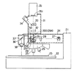
図1は、本発明が適用されるスポット照明付き観察系を備えた顕微鏡の概略構成を示している。
【0011】
図において、21は顕微鏡本体で、この顕微鏡本体21には、移動ステージ22を有し、この移動ステージ22上に液晶基板またはウェハなどの標本23を載置している。また、顕微鏡本体21には、移動ステージ22上方まで延びる中空の落射照明ユニット24を突設し、この落射照明ユニット24の先端部下方に倍率の異なる複数の対物レンズ25を有するレボルバ26を配置している。
【0012】
落射照明ユニット24は、その中空部に落射照明光源27、レンズ28および光路分割キューブ29を設けている。この場合、光路分割キューブ29は、レンズ28を通して与えられる落射照明光源27からの落射照明光を反射と透過の2方向に分割するもので、光路分割キューブ29で反射した落射照明光源27からの落射照明光を反射光路291に進めるとともに、透過した落射照明光を透過光路292に進めるようにしている。
【0013】
この場合、反射光路291に進んだ落射照明光は、対物レンズ25を通して移動ステージ22上に載置された標本23を照明し、標本23からの反射光、つまり反射光路291の逆方向から入射される観察光は、光路分割キューブ29を透過し透過光路293に進み、後述する接眼レンズユニット31に入射され、また、光路分割キューブ29を透過した落射照明光は、透過光路292に進んで、後述するスポット照明付き観察系36に入射するようになっている。
【0014】
光路分割キューブ29には、シャッタ30を設けている。このシャッタ30は、図2に示すように一対の長方形遮蔽板301、302をL字状に形成するとともに、遮蔽板301に透穴301aを、また遮蔽板302に透穴302aをそれぞれ形成したもので、これら遮蔽板301、302をアクチュエータ304の駆動力により、その長手方向に配置されたガイド303に沿って直線移動(図1では、紙面と垂直方向に直線移動)することにより、透穴301aを反射光路291中に、または透穴302aを透過光路292中にそれぞれ選択的に配置できるようにしている。ここで、シャッタ30をアクチュエータの代わりに手動で切り換えられるような機械的な切換機構を用いることもできる。また、アクチュエータ304は、モータまたはソレノイドのように電気的に制御可能なものや、エアや油圧で制御可能なものであってもよい。
【0015】
レボルバ26は、倍率の異なる複数の対物レンズ25のうちの1つを選択的に反射光路291中に挿入するためのものである。
落射照明ユニット24の先端部上方に接眼レンズユニット31を配置している。この接眼レンズユニット31は、結像レンズ32、2方向分割プリズム33および接眼レンズ34を有し、光路分割キューブ29の透過光路293に進んだ観察像を2方向分割プリズム33で2方向に分割し、このうち一方を接眼レンズ34の中間位置に結像し、また、他方を、TVカメラ35の撮像面351に結像するようにしている。
【0016】
また、落射照明ユニット24の先端にスポット照明付き観察系36を配置している。このスポット照明付き観察系36は、ミラー37と対物レンズ38を有し、光路分割キューブ29の透過光路292に進んだ落射照明光源27からの落射照明光をミラー37より対物レンズ38を通して移動ステージ22上の標本23をスポット照明し、標本23からの反射光を光路分割キューブ29で反射させ、透過光路294に進み、接眼レンズユニット31に入射するようにしている。
【0017】
次に、このように構成した実施の形態の動作を説明する。
まず、標本23に対しスポット照明付き観察を行う場合、シャッタ30をアクチュエータ304により駆動して、遮蔽板302の透穴302aを透過光路292中に配置する。この場合、反射光路291は、遮蔽板301により遮蔽される。
【0018】
この状態から、落射照明光源27を点灯すると、この落射照明光源27からの落射照明光は、レンズ28を通して光路分割キューブ29に入射され、ここで透過されて透過光路292に進み、スポット照明付き観察系36に入射される。
【0019】
これにより、落射照明光は、ミラー37により反射され対物レンズ38を通して移動ステージ22上の標本23をスポット照明する。この標本23から反射光が光路分割キューブ29で反射され、反射光路294に進み、接眼レンズユニット31の結像レンズ32、2方向分割プリズム33を介して接眼レンズ34の中間位置およびTVカメラ35の撮像面351に結像され、これら接眼レンズ34またはTVカメラ35により欠陥部位の観察が行われ、観察した欠陥部位をスポット照明位置に移動する。
【0020】
次に、このようにして観察された欠陥部位を、高倍率の顕微鏡観察する場合は、シャッタ30をアクチュエータ304により駆動して、今度は、遮蔽板301の透穴301aを反射光路291中に配置する。この場合、透過光路292は、遮蔽板302により遮蔽される。
【0021】
また、移動ステージ22を移動して、対物レンズ25に高倍率で観察したい欠陥部位を対応させる。
この状態から、落射照明光源27を点灯すると、この落射照明光源27からの落射照明光は、レンズ28を通して光路分割キューブ29に入射され、ここで反射されて反射光路291に進み、対物レンズ25を通して移動ステージ22上の標本23を照明するようになり、この標本23からの反射光が光路分割キューブ29を透過され、透過光路293を進み、接眼レンズユニット31の結像レンズ32、2方向分割プリズム33を介して接眼レンズ34の中間位置およびTVカメラ35の撮像面351に結像され、これら接眼レンズ34またはTVカメラ35により欠陥部位に対する高倍率の顕微鏡観察が行われる。
【0022】
従って、このようにすれば、顕微鏡本体21の落射照明光源27による落射照明光を光路分割キューブ29により反射光路291と透過光路292に分割するとともに、これら反射光路291および透過光路292のいずれか一方をシャッタ30により遮蔽可能にする。そして、シャッタ30により反射光路291を遮蔽している状態では、透過光路292を通った落射照明光による標本23のスポット照明像が接眼レンズユニット31に取込まれるとともに、接眼レンズ34およびTVカメラ35により欠陥部が低倍率で観察される。一方、シャッタ30により透過光路292を遮蔽している状態では、反射光路291を通った落射照明光による標本23の観察像が、同様に接眼レンズユニット31に取込まれ、接眼レンズ34およびTVカメラ35により欠陥部が高倍率で観察される。このようにして、スポット照明付き観察系に対する落射照明光源27および接眼レンズユニット31と、顕微鏡本体21による標本23の観察に対する落射照明光源27および接眼レンズユニット31を共用できるようにしているので、スポット照明付き観察系での部品点数を大幅に軽減でき、顕微鏡全体として小型で価格的のも安価にできる。また、落射照明光源27を共通にできることは、従来の2個の落射照明光源を用いたものに比べ、光源のメンテナンス工数を低減でき、取扱いを簡単なものにできる。さらに、スポット照明付き観察系についても、接眼レンズ34による接眼観察も可能にしたので、スポット照明付き観察系での観察をさらに確実なものにできる。
【0023】
なお、上述した実施の形態では、シャッタ30により光路分割キューブ29の反射光路291または透過光路292を選択的に遮蔽するようにしたが、これら反射光路291、透過光路292に各別にシャッタを設け、自動または手動によりそれぞれ独立して反射光路291または透過光路292を遮蔽するようにしてもよいし、さらに機械的なシャッタに代えて液晶シャッタを用いてもよい。また、上述した実施の形態では、対物レンズ25、38に無限遠対物レンズを用い、これら対物レンズ25または38と結像レンズ32により標本23の観察像を結像させる無限遠設計の顕微鏡について述べたが、対物レンズ25、38に有限遠対物レンズを用い、それぞれの結像位置を結像レンズ32およびTVカメラ35の撮像面351に直接合致させる有限遠設計の顕微鏡にも適用できる。また、このような有限遠設計の対物レンズの光路のどこかに、結像位置を変えるためのレンズを配置する光学系にも有効である。
【0024】
【発明の効果】
以上述べたように、本発明によれば、スポット照明用光学手段に対する照明用光源および観察用光学手段と観察照明用光学手段に対する照明用光源および観察用光学手段を共用できるので、スポット照明付き観察系での部品点数を軽減できる分、小型で価格的にも安価にできる。また、照明用光源を共通にできることから光源のメンテナンス工数を低減でき、取扱いを簡単なものにできる。さらに、スポット照明付き観察系での接眼観察も可能にできるので、スポット照明付き観察系での観察をさらに確実なものにできる。
【図面の簡単な説明】
【図1】 本発明の一実施の形態にかかるスポット照明付き観察系を備えた顕微鏡の概略構成を示す図。
【図2】 一実施の形態に適用されるシャッタ装置の概略構成を示す図。
【図3】 従来のスポット照明付き観察系を備えた顕微鏡の概略構成を示す図。
【符号の説明】
21…顕微鏡本体、
22…移動ステージ、
23…標本、
24…落射照明ユニット、
25…対物レンズ、
26…レボルバ、
27…落射照明光源、
28…レンズ、
29…光路分割キューブ、
291、294…反射光路、
292、293…透過光路、
30…シャッタ、
301、302…遮蔽板、
301a、302a…透穴、
303…ガイド、
304…アクチュエータ、
31…接眼レンズユニット、
32…結像レンズ、
33…2方向分割プリズム、
34…接眼レンズ、
35…TVカメラ、
351…撮像面、
36…スポット照明付き観察系、
37…ミラー、
38…対物レンズ。[0001]
BACKGROUND OF THE INVENTION
The present invention relates to a microscope having an observation system with spot illumination.
[0002]
[Prior art]
2. Description of the Related Art Conventionally, a microscope equipped with an observation system with spot illumination is used for pattern defect inspection and analysis of dust and scratches in manufacturing processes of liquid crystals and semiconductors.
FIG. 3 shows an example of a microscope equipped with such an observation system with spot illumination. In the microscope main body 1, epi-illumination light from the epi-
[0003]
In this case, the working distance WD of the observation system with
[0004]
[Problems to be solved by the invention]
However, according to such a configuration, the epi-
[0005]
The present invention has been made in view of the above circumstances, and an object of the present invention is to provide a microscope having an observation system with a spot illumination that can be simplified in configuration, small, and inexpensive.
[0006]
[Means for Solving the Problems]
The microscope according to the present invention includes a stage on which a specimen is placed, a high-magnification objective lens that magnifies the specimen arranged so that the optical axis is perpendicular to the specimen, and a high-magnification objective lens. An observation means for observing the sample image, an illumination light source for emitting illumination light in a direction orthogonal to the optical axis between the high-magnification objective lens and the observation means, and an extension of the emission direction of the illumination light source A reflecting member arranged on a line at a position away from the optical axis of the high-magnification objective lens, and deflecting the illumination light perpendicular to the specimen; and an optical axis perpendicular to the specimen in the reflected light path of the reflecting member A spot illumination objective lens that performs spot illumination on the specimen at a lower magnification than the high-magnification objective lens, and a position where the optical axis of the high-magnification objective lens and the optical axis of the spot illumination objective lens are orthogonal Arranged A direction in which the illumination light emitted from the illumination light source is reflected to the high-magnification objective lens side, a direction in which light reflected by the sample and passed through the high-magnification objective lens is transmitted to the observation means side, and the illumination light source An optical path dividing unit that divides the optical path into four in a direction in which the illumination light emitted from the light is transmitted to the reflecting member side and a direction in which the light reflected by the sample and passed through the spot illumination objective lens is reflected to the observation unit side It was characterized by comprising .
[0009]
As a result, according to the present invention, it is possible to share the observation means with a high-magnification objective lens and the spot illumination objective lens, amount that can reduce the number of parts can also be inexpensive price basis small, further, spotlighting The specimen can be observed at a low magnification by the objective lens.
[0010]
DETAILED DESCRIPTION OF THE INVENTION
Hereinafter, an embodiment of the present invention will be described with reference to the drawings.
FIG. 1 shows a schematic configuration of a microscope provided with an observation system with spot illumination to which the present invention is applied.
[0011]
In the figure,
[0012]
The epi-
[0013]
In this case, the epi-illumination light that has traveled to the reflected light path 291 illuminates the
[0014]
The optical
[0015]
The
An eyepiece unit 31 is disposed above the tip of the epi-
[0016]
An observation system with
[0017]
Next, the operation of the embodiment configured as described above will be described.
First, when performing observation with spot illumination on the
[0018]
In this state, when the epi-
[0019]
Thereby, the epi-illumination light is reflected by the
[0020]
Next, when the defect site observed in this way is observed with a high-magnification microscope, the
[0021]
In addition, the moving
When the epi-
[0022]
Therefore, according to this, the incident illumination light from the incident
[0023]
In the above-described embodiment, the reflected light path 291 or the transmitted
[0024]
【The invention's effect】
As described above, according to the present invention, the illumination light source and the observation optical means for the spot illumination optical means and the illumination light source and the observation optical means for the observation illumination optical means can be shared. Because the number of parts in the system can be reduced, it can be made small and inexpensive. Further, since the illumination light source can be made common, the maintenance work of the light source can be reduced and the handling can be simplified. Furthermore, since it is possible to perform eyepiece observation with an observation system with spot illumination, observation with an observation system with spot illumination can be further ensured.
[Brief description of the drawings]
FIG. 1 is a diagram showing a schematic configuration of a microscope including an observation system with spot illumination according to an embodiment of the present invention.
FIG. 2 is a diagram showing a schematic configuration of a shutter device applied to one embodiment.
FIG. 3 is a diagram showing a schematic configuration of a microscope including a conventional observation system with spot illumination.
[Explanation of symbols]
21 ... Microscope body,
22 ... Moving stage,
23 ... Sample,
24 ... Epi-illumination unit,
25 ... Objective lens,
26 ... Revolver,
27 ... Epi-illumination light source,
28 ... Lens,
29 ... Optical path division cube,
291, 294 ... reflected light path,
292, 293 ... transmitted light path,
30 ... Shutter,
301, 302 ... shielding plate,
301a, 302a ... through holes,
303 ... Guide,
304 ... Actuator,
31 ... eyepiece unit,
32 ... imaging lens,
33 ... Two-way split prism,
34 ... eyepiece,
35 ... TV camera,
351 ... Imaging surface,
36 ... Observation system with spot illumination,
37 ... Mirror,
38 ... Objective lens.
Claims (4)
前記標本に対して光軸が垂直になるように配置された前記標本を高倍に拡大する高倍対物レンズと、
前記高倍対物レンズを介して取込まれた標本像を観察する観察手段と、
前記高倍対物レンズと前記観察手段との間の光軸に対して直行する方向に照明光を出射する照明光源と、
前記照明光源の出射方向の延長線上で前記高倍対物レンズの光軸から離れた位置に配置され前記照明光を前記標本に対して垂直に偏向する反射部材と、
前記反射部材の反射光路に前記標本に対して光軸が垂直になるように配置され、前記高倍対物レンズより低倍で前記標本上にスポット照明を行なうスポット照明用対物レンズと、
前記高倍対物レンズの光軸と前記スポット照明用対物レンズの光軸が直行する位置に配置され、前記照明光源から出射された照明光を前記高倍対物レンズ側に反射させる方向と、前記標本で反射し前記高倍対物レンズを通過した光を前記観察手段側に透過させる方向と、前記照明光源から出射された照明光を前記反射部材側に透過させる方向と、前記標本で反射し前記スポット照明用対物レンズを通過した光を前記観察手段側に反射させる方向に光路を4分割する光路分割手段と
を具備したことを特徴とする顕微鏡。A stage for placing the specimen;
A high-magnification objective lens that magnifies the specimen that is arranged so that the optical axis is perpendicular to the specimen;
Observation means for observing a sample image captured through the high-magnification objective lens;
An illumination light source that emits illumination light in a direction perpendicular to the optical axis between the high-magnification objective lens and the observation means;
A reflecting member that is disposed at a position away from the optical axis of the high-magnification objective lens on an extended line in the emission direction of the illumination light source, and deflects the illumination light perpendicular to the sample;
An objective lens for spot illumination that is arranged so that the optical axis is perpendicular to the specimen in the reflection optical path of the reflecting member, and performs spot illumination on the specimen at a lower magnification than the high-magnification objective lens;
The optical axis of the high-magnification objective lens and the optical axis of the spot illumination objective lens are arranged at a position orthogonal to each other, and the direction in which the illumination light emitted from the illumination light source is reflected toward the high-magnification objective lens and reflected by the sample A direction in which the light that has passed through the high-magnification objective lens is transmitted to the observation means side, a direction in which the illumination light emitted from the illumination light source is transmitted to the reflection member side, and reflected by the sample to be reflected by the spot illumination objective A microscope comprising: an optical path dividing unit that divides an optical path into four in a direction in which light passing through a lens is reflected to the observation unit side .
Priority Applications (1)
| Application Number | Priority Date | Filing Date | Title |
|---|---|---|---|
| JP23022996A JP3854665B2 (en) | 1996-08-30 | 1996-08-30 | microscope |
Applications Claiming Priority (1)
| Application Number | Priority Date | Filing Date | Title |
|---|---|---|---|
| JP23022996A JP3854665B2 (en) | 1996-08-30 | 1996-08-30 | microscope |
Publications (2)
| Publication Number | Publication Date |
|---|---|
| JPH1073767A JPH1073767A (en) | 1998-03-17 |
| JP3854665B2 true JP3854665B2 (en) | 2006-12-06 |
Family
ID=16904572
Family Applications (1)
| Application Number | Title | Priority Date | Filing Date |
|---|---|---|---|
| JP23022996A Expired - Fee Related JP3854665B2 (en) | 1996-08-30 | 1996-08-30 | microscope |
Country Status (1)
| Country | Link |
|---|---|
| JP (1) | JP3854665B2 (en) |
Families Citing this family (8)
| Publication number | Priority date | Publication date | Assignee | Title |
|---|---|---|---|---|
| WO2001071406A1 (en) * | 2000-03-24 | 2001-09-27 | Olympus Optical Co., Ltd. | Microscope unit |
| JP2002182123A (en) * | 2000-12-11 | 2002-06-26 | Nikon Corp | Microscope device |
| KR100566087B1 (en) * | 2004-04-22 | 2006-03-30 | 정권용 | Mobile microscope for checking real time welding of laser welding machine |
| JP5021942B2 (en) * | 2006-02-28 | 2012-09-12 | 日立オムロンターミナルソリューションズ株式会社 | Image sensor, identification device and correction method thereof |
| DE102008041822B4 (en) * | 2008-09-04 | 2011-06-22 | Leica Microsystems CMS GmbH, 35578 | An optical system for merging a first and a second field beam respectively emanating from an object into a resulting image beam |
| CN103955050B (en) * | 2014-05-13 | 2016-08-24 | 杨征 | A kind of multi-pass microscopic system |
| JP2020507106A (en) * | 2016-12-30 | 2020-03-05 | ライカ バイオシステムズ イメージング インコーポレイテッドLeica Biosystems Imaging, Inc. | Low resolution slide imaging, slide label imaging and high resolution slide imaging using dual optical paths and a single imaging sensor |
| WO2019068039A1 (en) * | 2017-09-29 | 2019-04-04 | Leica Biosystems Imaging, Inc. | Two pass macro image |
-
1996
- 1996-08-30 JP JP23022996A patent/JP3854665B2/en not_active Expired - Fee Related
Also Published As
| Publication number | Publication date |
|---|---|
| JPH1073767A (en) | 1998-03-17 |
Similar Documents
| Publication | Publication Date | Title |
|---|---|---|
| US20070146871A1 (en) | Microscope and sample observation method | |
| US7564624B2 (en) | Microscope | |
| JP3854665B2 (en) | microscope | |
| KR100806023B1 (en) | Microscope unit | |
| JP2017523469A (en) | Methods for optical inspection and / or manipulation of microscopes and microsamples | |
| JP3944285B2 (en) | Board inspection equipment | |
| US11709137B2 (en) | Light sheet fluorescence microscope | |
| JP4720078B2 (en) | Microscope barrel | |
| JP4406108B2 (en) | Multiphoton excitation laser microscope | |
| JPH0530823U (en) | System microscope | |
| JP2000275594A (en) | Substrate inspecting device | |
| JP3735936B2 (en) | Surgical microscope | |
| JP4128260B2 (en) | microscope | |
| JP2002006224A (en) | Dark/bright field vertical illuminating device for microscope | |
| CN116490811A (en) | Microscope | |
| JPH11133211A (en) | Filter switching device | |
| US7835075B2 (en) | Replacement device for microscopes | |
| JP3176678B2 (en) | Microscope lighting device | |
| JP2013190760A (en) | Illuminator for microscope | |
| JP2002098906A (en) | Microscope | |
| JP3644997B2 (en) | Laser processing equipment | |
| JP2000056234A (en) | Microscope | |
| JP3557261B2 (en) | microscope | |
| JP3204712B2 (en) | High to very low magnification microscope | |
| JPH0618956U (en) | Oblique illumination device for visual inspection |
Legal Events
| Date | Code | Title | Description |
|---|---|---|---|
| A977 | Report on retrieval |
Free format text: JAPANESE INTERMEDIATE CODE: A971007 Effective date: 20051110 |
|
| A131 | Notification of reasons for refusal |
Free format text: JAPANESE INTERMEDIATE CODE: A131 Effective date: 20051206 |
|
| A521 | Written amendment |
Free format text: JAPANESE INTERMEDIATE CODE: A523 Effective date: 20060203 |
|
| TRDD | Decision of grant or rejection written | ||
| A01 | Written decision to grant a patent or to grant a registration (utility model) |
Free format text: JAPANESE INTERMEDIATE CODE: A01 Effective date: 20060905 |
|
| A61 | First payment of annual fees (during grant procedure) |
Free format text: JAPANESE INTERMEDIATE CODE: A61 Effective date: 20060911 |
|
| FPAY | Renewal fee payment (event date is renewal date of database) |
Free format text: PAYMENT UNTIL: 20090915 Year of fee payment: 3 |
|
| FPAY | Renewal fee payment (event date is renewal date of database) |
Free format text: PAYMENT UNTIL: 20100915 Year of fee payment: 4 |
|
| FPAY | Renewal fee payment (event date is renewal date of database) |
Free format text: PAYMENT UNTIL: 20110915 Year of fee payment: 5 |
|
| LAPS | Cancellation because of no payment of annual fees |