JP3833879B2 - Endoscope device - Google Patents
Endoscope device Download PDFInfo
- Publication number
- JP3833879B2 JP3833879B2 JP2000237312A JP2000237312A JP3833879B2 JP 3833879 B2 JP3833879 B2 JP 3833879B2 JP 2000237312 A JP2000237312 A JP 2000237312A JP 2000237312 A JP2000237312 A JP 2000237312A JP 3833879 B2 JP3833879 B2 JP 3833879B2
- Authority
- JP
- Japan
- Prior art keywords
- endoscope
- sterilization
- bending
- pressure
- predetermined
- Prior art date
- Legal status (The legal status is an assumption and is not a legal conclusion. Google has not performed a legal analysis and makes no representation as to the accuracy of the status listed.)
- Expired - Fee Related
Links
Images


Classifications
-
- A—HUMAN NECESSITIES
- A61—MEDICAL OR VETERINARY SCIENCE; HYGIENE
- A61L—METHODS OR APPARATUS FOR STERILISING MATERIALS OR OBJECTS IN GENERAL; DISINFECTION, STERILISATION OR DEODORISATION OF AIR; CHEMICAL ASPECTS OF BANDAGES, DRESSINGS, ABSORBENT PADS OR SURGICAL ARTICLES; MATERIALS FOR BANDAGES, DRESSINGS, ABSORBENT PADS OR SURGICAL ARTICLES
- A61L2/00—Methods or apparatus for disinfecting or sterilising materials or objects other than foodstuffs or contact lenses; Accessories therefor
- A61L2/26—Accessories or devices or components used for biocidal treatment
-
- A—HUMAN NECESSITIES
- A61—MEDICAL OR VETERINARY SCIENCE; HYGIENE
- A61L—METHODS OR APPARATUS FOR STERILISING MATERIALS OR OBJECTS IN GENERAL; DISINFECTION, STERILISATION OR DEODORISATION OF AIR; CHEMICAL ASPECTS OF BANDAGES, DRESSINGS, ABSORBENT PADS OR SURGICAL ARTICLES; MATERIALS FOR BANDAGES, DRESSINGS, ABSORBENT PADS OR SURGICAL ARTICLES
- A61L2/00—Methods or apparatus for disinfecting or sterilising materials or objects other than foodstuffs or contact lenses; Accessories therefor
- A61L2/02—Methods or apparatus for disinfecting or sterilising materials or objects other than foodstuffs or contact lenses; Accessories therefor using physical phenomena
- A61L2/04—Heat
- A61L2/06—Hot gas
- A61L2/07—Steam
-
- A—HUMAN NECESSITIES
- A61—MEDICAL OR VETERINARY SCIENCE; HYGIENE
- A61L—METHODS OR APPARATUS FOR STERILISING MATERIALS OR OBJECTS IN GENERAL; DISINFECTION, STERILISATION OR DEODORISATION OF AIR; CHEMICAL ASPECTS OF BANDAGES, DRESSINGS, ABSORBENT PADS OR SURGICAL ARTICLES; MATERIALS FOR BANDAGES, DRESSINGS, ABSORBENT PADS OR SURGICAL ARTICLES
- A61L2202/00—Aspects relating to methods or apparatus for disinfecting or sterilising materials or objects
- A61L2202/10—Apparatus features
- A61L2202/12—Apparatus for isolating biocidal substances from the environment
- A61L2202/122—Chambers for sterilisation
-
- A—HUMAN NECESSITIES
- A61—MEDICAL OR VETERINARY SCIENCE; HYGIENE
- A61L—METHODS OR APPARATUS FOR STERILISING MATERIALS OR OBJECTS IN GENERAL; DISINFECTION, STERILISATION OR DEODORISATION OF AIR; CHEMICAL ASPECTS OF BANDAGES, DRESSINGS, ABSORBENT PADS OR SURGICAL ARTICLES; MATERIALS FOR BANDAGES, DRESSINGS, ABSORBENT PADS OR SURGICAL ARTICLES
- A61L2202/00—Aspects relating to methods or apparatus for disinfecting or sterilising materials or objects
- A61L2202/20—Targets to be treated
- A61L2202/24—Medical instruments, e.g. endoscopes, catheters, sharps
Description
【0001】
【発明の属する技術分野】
本発明は、高圧蒸気滅菌の際、挿入部に軟性部を有する内視鏡を収納する内視鏡補助具を備えた内視鏡装置に関する。
【0002】
【従来の技術】
従来より、細長の挿入部を体腔内に挿入することにより、体腔内臓器などを観察したり、必要に応じて処置具チャンネル内に挿通した処置具を用いて各種治療処置の行える医療用の内視鏡が広く利用されている。
【0003】
医療分野で使用される内視鏡は、挿入部を体腔内に挿入して、臓器などを観察したり、内視鏡の処置具チャンネル内に挿入した処置具を用いて、各種治療や処置を行う。このため、一度使用した内視鏡や処置具を他の患者に再使用する場合には、内視鏡や処置具を介しての患者間感染を防止する必要から、検査・処置終了後に内視鏡装置の洗滌消毒を行わなければならなかった。
【0004】
近年では、煩雑な作業を伴わず、滅菌後直ちに使用が可能で、ランニングコストが安価なオートクレーブ滅菌(高圧蒸気滅菌)が内視鏡機器の消毒滅菌処理の主流になりつつある。
【0005】
例えば特開平5−285103号公報には内視鏡の機能に悪影響を与えることなく内視鏡をオートクレーブ滅菌する内視鏡用オートクレーブ装置が示されている。
【0006】
この高圧蒸気滅菌の環境は、精密電子機器である内視鏡にとって非常に過酷な条件である。このため、この条件に耐性を有する内視鏡を実現させるため、一般の消毒・滅菌手段での使用を前提にした内視鏡に比べ、高圧対策、高温対策、蒸気対策等、様々な対策を施している。
【0007】
【発明が解決しようとする課題】
しかしながら、挿入部に軟性部を有する内視鏡では、その挿入部長が長いため、この挿入部を丸めた状態にして高圧蒸気滅菌装置内に配置しなければならず、この状態で高圧蒸気滅菌を行うと、軟性部に丸めた際の曲がり癖が付き、高圧蒸気滅菌後の検査の際、この軟性部の曲がり癖によって挿入性が低下するおそれがあった。
【0008】
本発明は上記事情に鑑みてなされたものであり、内視鏡を高圧蒸気滅菌した際、軟性部に曲がり癖がつくことによって挿入性が低下することを防止する内視鏡補助具を備えた内視鏡装置を提供することを目的にしている。
【0009】
【課題を解決するための手段】
本発明の内視鏡装置は、挿入部に軟性部を有する高圧蒸気滅菌に対応する下部消化管用の内視鏡と、高圧蒸気滅菌を行う際、前記内視鏡を収納する内視鏡補助具とを備える内視鏡装置であって、
前記内視鏡補助具は、前記内視鏡が着脱可能で、前記軟性部の所定部位の曲げ半径が他の部位の曲げ半径より大きくなるように規制する位置決め部を有し、
前記所定部位は、少なくとも挿入部先端から70cmまでの部位を含む軟性部であることを特徴とする内視鏡装置。
【0010】
この構成によれば、下部消化器官用の内視鏡を内視鏡補助具に収納して高圧蒸気滅菌を行うことによって、位置決め部によって所定の状態に規制された軟性部の所定部位に挿入性を損なう曲がり癖がつくことが防止される。
【0011】
【発明の実施の形態】
以下、図面を参照して本発明の実施の形態を説明する。
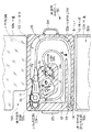
図1ないし図3は本発明の一実施形態に係り、図1は内視鏡装置の全体構成を示す図、図2は滅菌用収納ケースに内視鏡を配置させた状態を示す図、図3は内視鏡を滅菌用収納ケースに収納した状態を示す図である。
【0012】
なお、図3(a)はトレー本体に中蓋を被せた状態を示す図、図3(b)は外蓋で覆った状態を示す図である。
【0013】
図1に示すように本実施形態の内視鏡装置1は、撮像手段を備えた電子内視鏡(以下内視鏡と記載する)2と、照明光を供給する光源装置3と、撮像手段を制御するとともに前記撮像手段から得られる信号を処理するビデオプロセッサ4と、このビデオプロセッサ4に接続されたモニタ5とで主に構成されている。なお、符号50はこの内視鏡2を収納する後述する内視鏡補助具となる滅菌用収納ケースである。
【0014】
前記内視鏡2は、細長で可撓性を有する挿入部10と、この挿入部10の基端部に連設する操作部11と、この操作部11の側方から延出する可撓性を有するユニバーサルコード12とで構成されている。
【0015】
前記ユニバーサルコード12の端部には前記光源装置3に着脱自在なコネクタ12aが設けられている。このコネクタ12aを光源装置3に接続することによって、光源装置3に備えられている図示しないランプからの照明光が内視鏡2の図示しないライトガイドを伝送されて観察部位を照射するようになっている。
【0016】
前記挿入部10と操作部との接続部分には急激な曲がりを防止する弾性部材で構成された挿入部折れ止め部材7aが設けられ、前記操作部11とユニバーサルコード12との接続部分には同様に操作部折れ止め部材7bが設けられ、そしてユニバーサルコード12とコネクタ12aとの接続部分には同様にコネクタ折れ止め部材7cが設けられている。
【0017】
前記内視鏡2の細長で可撓性を有する挿入部10は、先端側から順に硬性で例えば先端面に図示しない観察窓や照明窓などを配設した先端硬性部13,複数の湾曲駒を連接して湾曲自在な湾曲部14、微妙な柔軟性と弾発性とからなる可撓性を有する軟性部である可撓管部15とを連設して構成されている。前記湾曲部14は、操作部11に設けられている湾曲操作ノブ16を適宜操作することによって湾曲し、観察窓等を配設した先端硬性部13の先端面を所望の方向に向けられるようになっている。
【0018】
前記操作部11には前記湾曲操作ノブ16の他に先端面に設けた図示しない送気送水ノズルから前記観察窓に向けて洗滌液体や気体を噴出させる際の送気操作、送水操作を行う送気送水操作ボタン17及び先端面に設けた図示しない吸引口を介して吸引操作を行うための吸引操作ボタン18、前記ビデオプロセッサ4を遠隔操作する複数のリモートスイッチ19,…,19や内視鏡2の挿入部内に配置された処置具チャンネルに連通する処置具挿入口20が設けられている。
【0019】
前記コネクタ12aの側部には電気コネクタ部12bが設けられている。この電気コネクタ部12bには前記ビデオプロセッサ4に接続された信号コード6の信号コネクタ6aが着脱自在に接続される。この信号コネクタ6aをビデオプロセッサ4に接続することによって、内視鏡2の撮像手段を制御するとともに、この撮像手段から伝送される電気信号から映像信号を生成して、内視鏡観察画像を前記モニタ5の画面上に表示する。なお、電気コネクタ部12bには内視鏡2の内部と外部とを連通する図示しない通気口が設けられている。このため、前記内視鏡2の電気コネクタ部12bには前記通気口を塞ぐ圧力調整弁(不図示)を設けた圧力調整弁付き防水キャップ(以下防水キャップと略記する)9aが着脱自在な構成になっている。
【0020】
また、このコネクタ12aには光源装置3に内蔵されている図示しない気体供給源に着脱自在に接続される気体供給口金12cや、液体供給源である送水タンク8に着脱自在に接続される送水タンク加圧口金12d及び液体供給口金12e、前記吸引口より吸引を行うための図示しない吸引源が接続される吸引口金12f、送水を行うための図示しない送水手段と接続される注入口金12gが設けられている。
【0021】
さらに、高周波処置等を行った際、内視鏡2に高周波漏れ電流が発生した場合、この漏れ電流を図示しない高周波処置装置に帰還させるためのアース端子口金12hが設けられている。
【0022】
前記内視鏡2は、観察や処置に使用された際、洗滌後、高圧蒸気滅菌を行うことが可能に構成されており、この内視鏡2を高圧蒸気滅菌する際には前記防水キャップ9aを電気コネクタ部12bに取り付ける。
【0023】
そして、前記内視鏡2を高圧蒸気滅菌する際には、この内視鏡2を収容器である滅菌用収納ケース50に収納する。この滅菌用収納ケース50は、ケース本体であるトレイ51と蓋部材52とで構成され、このトレイ51には内視鏡2を所定形状に収まるように規制する位置決め部を有している。また、これらトレイ51及び蓋部材52には高圧蒸気を導くための通気孔が複数形成されている。このため、トレイ51に蓋部材52を被せて一体にしたとき、ケース内部は非気密的な状態である。
【0024】
ここで、図2及び図3を参照して滅菌用収納ケース50を説明する。
図2に示すように滅菌用収納ケース50は、前記トレイ51であるトレイ本体53に、開閉自在な蓋部材52として薄板状の中蓋52a、箱状の外蓋52bとが取り付けられている。本実施形態においては中蓋52a及び外蓋52bを、前記トレイ本体53に対して観音開き構造としている。
【0025】
前記内視鏡2の可撓管部15には短いものから長いものまである。そして、本実施形態のように可撓管部15の長い機種では、挿入部10、ユニバーサルコード12を曲げた状態にしないと、内視鏡の滅菌を行う比較的小型な高圧蒸気滅菌装置に配置することができない。このため、前記トレイ本体53に、操作部11、コネクタ12a、挿入部10の所定部位等を所定の位置に収納配置させるための位置決め部が設けてあり、前記操作部11、コネクタ12a、挿入部10の先端硬性部13を所定の収納場所である凹部53a,53b,53cに配置することによって、ユニバーサルコード12や挿入部10の収納形態(曲げ形状が)が図に示すように決定されるようにしている。
【0026】
つまり、前記トレイ本体53には前記操作部11の位置を規制する位置決め部を兼ねる収納部である操作部用凹部53aや前記コネクタ12aの位置を規制する位置決め部を兼ねる収納部であるコネクタ用凹部53b、前記先端硬性部13を含む挿入部10の所定部位を規制する位置決め部を兼ねる収納部である所定部位用凹部53c及び内視鏡2のユニバーサルコード12や挿入部10の所定部位を除く他の部位を収納する収納用凹部53d、前記内視鏡2から取り外された送気送水操作ボタン17、吸引操作ボタン18や検査時に処置具挿入口20に取り付けられていた処置具栓処置具栓31などの小物を収納する小物用凹部53eが設けられている。
【0027】
前記所定部位とは挿入性に大きな影響を及ぼす部位であり、本実施形態においては後述するが、前記先端硬性部13、湾曲部14及び可撓管部15の先端側である。
【0028】
前記可撓管部15が長い機種である下部消化管用内視鏡の場合、挿入部長が例えば133cmや168cm等であるが、一般的に、大腸の肛門から盲腸部までを極力余分な撓みを除くようにして挿入させた場合(最短距離で挿入させたときには)、約70cmまでの部分が挿入される。
【0029】
つまり、この70cmまでの部分は殆ど全ての患者に対して挿入される部分であり、このように挿入される約70cmまでの部分が軟性部の所定部位であり、特にこの部位を略ストレート形状又はストレート形状に近い非常に緩やかな曲げ形状(曲げ半径の大きな形状)で収納されるようにトレイ本体53の凹部53a,53b,53c,53dを構成している。このことにより、前記トレイ本体53の凹部53a,53b,53c,53dに内視鏡2を収納配置すると、挿入部10は図に示す収納形態になり、図中矢印A部分が先端硬性部13の先端から約70cmの位置になる。つまり、この収納形態において軟性部の所定部位は、略ストレート形状で収納配置される。
【0030】
なお、前記凹部53a,53b,53cは、配置される操作部11やコネクタ12a、先端硬性部13,湾曲部14,可撓管部15の先端側が大きくスライドすることなく、かつ配置及び取り出しを容易に行え、高圧蒸気が周囲に対して十分に行き渡るよう、操作部11,コネクタ12a,先端硬性部13,湾曲部14,可撓管部15の外形寸法に対して所定のクリアランスを設けて形作られている。
【0031】
また、前記凹部53a,53b,53c,53dの深さ寸法は、それぞれ操作部11やコネクタ12a、挿入部10、ユニバーサルコード12がトレイ本体53上面より出っ張らない深さ寸法に設定されている。しかし、前記操作部11を操作部用凹部53aに配置した際、湾曲操作ノブ16は前記トレイ本体53の上面より突出する深さ寸法になっている。したがって、前記湾曲操作ノブ16を除いた操作部11やコネクタ12a、先端硬性部13、湾曲部14、可撓管部15ユニバーサルコード12は凹部53a,53b,53c,53d内に完全に配置された状態になる。
【0032】
さらに、前記凹部53a,53bの形状は、前記内視鏡2に送気送水操作ボタン17、吸引操作ボタン18、処置具栓31が取り付けられたままの状態で内視鏡2をトレイ本体53に収納配置させようとした場合、収納されないようにクリアランスに工夫が施されている。つまり、前記送気送水操作ボタン17、吸引操作ボタン18、処置具栓31を取り外した状態でトレイ本体53に収納配置することが可能で、このとき、内視鏡2内の管路内や、内視鏡2と送気送水操作ボタン17、吸引操作ボタン18、処置具栓31との接続部等に高圧蒸気滅菌時の高圧蒸気が十分に行き渡るようになっている。
【0033】
前記滅菌用収納ケース50の薄板状の中蓋52aには切欠部52cが形成されている。図3(a)に示すようにこの中蓋52aをトレイ本体53の上面に被せて前記凹部53a,53b,53c,53d,53eを塞ぐように配置させることによって、前記切欠部52cから前記湾曲操作ノブ16が突出する。
【0034】
前記中蓋52aをトレイ本体53の上面に被せることによって、内視鏡2の挿入部10、操作部11、ユニバーサルコード12は、トレイ本体53及び中蓋52a以外の他の物に当たることなく、所定のクリアランスを持った状態で位置決め収納される。そして、この中蓋52aの上には処置具32や洗浄具33が置かれるようになっている。なお、この中蓋52aは、透明部材で形成することが望ましく、着色されていてもよい。
【0035】
一方、前記滅菌用収納ケース50の箱状の外蓋52bには前記処置具32や洗浄具33を収納配置させる空間となる窪み部52dが設けられ、外周側部には前記滅菌用収納ケース50を例えば縦状態にして持ち運ぶ時にしっかりと握られる運搬用取っ手34と、この滅菌用収納ケース50を例えば水平状態で持つ際に把持する把持部35とが設けられている。
【0036】
そして、前記蓋部材52は、中蓋52a、外蓋52bの順に閉じる構成であり、その逆では蓋を閉じることができないようになっている。
【0037】
ここで、内視鏡2を高圧蒸気滅菌する際の代表的な条件について説明する。
この代表的な条件としては米国規格協会承認、医療機器開発協会発行の米国規格ANSI/AAMI ST37−1992に、プレバキュームタイプで滅菌工程1処置具挿入口20°Cで4分、グラビティタイプで滅菌工程1処置具挿入口20°Cで10分とされている。
【0038】
高圧蒸気滅菌の滅菌工程時の温度条件については、高圧蒸気滅菌装置の形式や滅菌工程の時間によって異なるが、一般的には操作部115°Cから138°C程度の範囲で設定される。滅菌装置の中には142°C程度に設定可能なものもある。
【0039】
時間条件については滅菌工程の温度条件によって異なる。一般的には3〜60分程度に設定される。滅菌装置の種類によっては100分程度に設定可能なものもある。
【0040】
そして、この工程での滅菌装置内の圧力は一般的には大気圧に対して+0.2MPa程度に設定される。
【0041】
次に、一般的なプレバキュームタイプにおける内視鏡の高圧蒸気滅菌工程を簡単に説明する。
まず、滅菌対象機器である内視鏡2の電気コネクタ部12bに防水キャップ9aを取り付け、滅菌用収納ケース50のトレイ本体53の凹部53a,53b,53c,53dに内視鏡2を収納し、小物用凹部53eに送気送水操作ボタン17、吸引操作ボタン18、処置具栓処置具栓31などを収容する。そして、中蓋52aでトレイ本体53を覆い、このトレイ本体53を覆う中蓋52aの上に処置具32や洗浄具33を配置した後、図3(b)に示すように外蓋52bを被せて一体にし、滅菌装置内に配置する。
【0042】
前記電気コネクタ部12bに防水キャップ9aを取り付けたことにより、圧力調整弁が閉じた状態になって前記通気口を塞ぐ。すなわち、内視鏡2の内部と外部とが水密的に密閉される。そして、高圧滅菌工程前の滅菌装置内を減圧状態(プレバキューム工程)にする。
【0043】
なお、このプレバキューム工程とは、滅菌工程時に滅菌対象機器の細部にまで蒸気を浸透させるための工程であり、滅菌装置内を減圧させることにより、滅菌対象機器全体に高圧高温蒸気が行き渡るようになる。このプレバキューム工程における滅菌装置内の圧力は、一般的に大気圧に対して−0.07〜−0.09MPa程度に設定される。
【0044】
しかし、プレバキューム工程において、滅菌装置内の圧力が減少すると、内視鏡2の内部圧力に対して外部圧力が低くなって圧力差が生じる。すると、前記防水キャップ9aの圧力調整弁が開いて、前記通気口を介して内視鏡2の内部と外部とが連通状態になる。このことによって、圧力差が大きく生じることを防ぐ。つまり、内視鏡2が内部圧力と外部圧力との圧力差によって破損することが防止される。
【0045】
次に、滅菌装置内に高圧高温蒸気を送り込んで滅菌を行う(滅菌工程)。
この滅菌工程においては滅菌装置内が加圧される。すると、内視鏡2の内部圧力より外部圧力の方が高くなるような圧力差が生じる。このため、前記防水キャップ9aの圧力調整弁が閉じ、高圧蒸気が通気口を通過して内視鏡内部に侵入することを遮断する。
【0046】
高圧蒸気は、前記トレイ本体53及び蓋部材52である中蓋52a、外蓋52bに複数形成されている通気孔を介して滅菌用収納ケース50内に侵入し、高分子材料で形成されている前記可撓管15の外皮チューブ15cや内視鏡2の外装体の接続部に設けられたシール手段であるフッ素ゴムやシリコンゴム等で形成されたOリング等を透過して内視鏡内部に徐々に侵入していく。
【0047】
このとき、内視鏡2の外装体にはプレバキューム工程で減圧された圧力と滅菌工程で加圧された圧力とが加算された、外部から内部に向けた圧力が生じた状態になる。
【0048】
次いで、滅菌後の滅菌対象機器を乾燥させるため、滅菌工程終了後、滅菌装置内を再度減圧状態にして乾燥(乾燥工程)を行う。この乾燥工程では、滅菌装置内を減圧して滅菌装置内から蒸気を排除して滅菌装置内の滅菌対象機器の乾燥を促進する。この乾燥工程における滅菌装置内の圧力は一般的には大気圧に対して−0.07MPa〜−0.09MPa程度に設定される。なお、前記乾燥工程は必要に応じて任意に行うものである。
【0049】
滅菌工程後の減圧工程では、滅菌装置内の圧力が減少して内視鏡2の内部圧力より外部圧力が低くなるような圧力差が生じる。この圧力差が生じると略同時に前記防水キャップ9aの圧力調整弁が開き、通気口を介して内視鏡2の内部と外部とが連通状態になり、内視鏡内部と外部との間に大きな圧力差が生じることが防止される。そして、減圧工程が終了して、滅菌装置内が加圧されて、内視鏡2の内部圧力よりも外部圧力の方が高くなるような圧力差が生じると前記防水キャップ9aの圧力調整弁が閉じる。
【0050】
なお、高圧蒸気滅菌全工程終了時、内視鏡2の外装体には減圧工程で減圧された分、外部から内部に向けた圧力が生じた状態になる。そして、防水キャップ9aを電気コネクタ部12bから取り外すことにより、前記通気口によって内視鏡2の内部と外部とが連通して、内視鏡2の内部は大気圧となり、内視鏡2の外装体に生じていた圧力差による負荷がなくなる。
【0051】
上述したように滅菌工程中、内視鏡2の内部及び外部は高圧蒸気にさらされる。このとき、滅菌用収納ケース50に収納配置された内視鏡2の所定部位である先端硬性部13の先端から約70cmまでが略ストレート形状で収納配置されているので、高圧蒸気にさらされても挿入性に大きく影響する可撓管部15の先端側である所定部位に曲がり癖が付くことが防止される。
【0052】
このように、滅菌用収納ケースを構成するトレイ本体に、挿入性に大きな影響を及ぼす可撓管部の先端側である、軟性部の所定部位を略ストレート形状に規制するための操作部用凹部、コネクタ用凹部、所定部位用凹部等の位置決め部を設けたことによって、内視鏡をトレイ本体に収納配置させることによって、簡単に軟性部の所定部位をストレート形状に配置させてることができるので、高圧蒸気滅菌を行った際に、軟性部の所定部位に曲がり癖が付くことを防止することができる。このことによって、高圧蒸気滅菌工程後、挿入部の挿入性が変化しない。
【0053】
なお、本実施形態においては、挿入部の先端側から70cmまでを略ストレート形状にする構成にしているが、高圧蒸気滅菌装置内に余裕がある場合には、ストレート形状部を70cmより更に長くするとよい。
【0054】
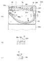
図4及び図5は本発明の第2実施形態に係り、図4は滅菌用収納ケースの他の構成を示す図、図5は滅菌用収納ケースの具体的な構成を説明する図である。
【0055】
図5(a)は閉じた状態の中蓋の上に挿入部を配置した状態を説明する図、図5(b)は図5(a)に示すB−B線断面図、図5(c)は図5(a)に示すC−C線断面図である。
【0056】
図4に示すように本実施形態の滅菌用収納ケース50Aは、内視鏡2の操作部11、ユニバーサルコード12、コネクタ12aを収納配置する操作部用凹部53a、ユニバーサルコード用凹部53f、コネクタ用凹部53bや送気送水操作ボタン17、吸引操作ボタン18、処置具栓処置具栓31及び洗浄ブラシ36等を収納する小物用凹部53e及び処置具32a,32bを収納する処置具用凹部53gを設けたトレイ本体53Aと、このトレイ本体53Aの一方側に取り付けられた一点鎖線に示すように開閉自在な中蓋55a及び二点鎖線に示すように開閉自在な外蓋55bとで構成されている。
【0057】
前記中蓋55aは、前記トレイ本体53A上の実線に示す部分までを覆うように構成されており、この中蓋55aをトレイ本体53上に配置させることによって、前記凹部53e,53f,53gの全体及びコネクタ用凹部53bの一部を覆って、内視鏡2のユニバーサルコード12やコネクタ12aが、このトレイ本体53A、中蓋55a以外の他の物に当たることなく、所定のクリアランスを持った状態で位置決め収納される。
【0058】
前記凹部53a,53f,53bに前記内視鏡2の操作部11、ユニバーサルコード12、コネクタ12aを収納配置したとき、前記挿入部10はトレイ本体53A上に配置され、その大部分がトレイ本体53Aから突出する。
【0059】
そして、この状態で、前記中蓋55aを閉状態にして凹部53e,53f,53gの全体及びコネクタ用凹部53bの一部を覆い、図5(a)に示すように前記トレイ本体53Aから突出した挿入部10を中蓋55aの上面に設けられている曲げ半径を所定の値に設定した曲壁56に沿わせて配置する。このことによって、前記挿入部10の先端側の軟性部は非常に緩やかな曲げ形状になる。なお、この曲壁56の曲げ半径は、前記挿入部手元側の曲げ半径より大きく設定されている。
【0060】
この配置状態状態のとき、図5(b)に示すように前記中蓋55aは、トレイ本体53に形成されている段部54に配置されているので、中蓋55aの上面とトレイ本体53Aの上面とが略同一平面になっている。このため、挿入部10を構成する可撓管部15がトレイ本体53A上から中蓋55a上に段差部などを経ることなく配置される。
【0061】
なお、図5(a)に示すように曲壁56は、前記挿入部10の先端硬性部13及び湾曲部14を所定のクリアランスで配置させる挿入部先端配置部56aを形成しており、この挿入部先端配置部56aに挿入部10の先端硬性部13及び湾曲部14を配置させることによって、可撓管部15が曲壁56に沿って配置されるようになっている。
【0062】
また、図5(c)に示すように前記曲壁56の高さ寸法は、可撓管部15の径寸法より大きく形成されている。そして、前記外蓋55bをトレイ本体53に被せたとき、中蓋55aの上に配置されいる可撓管部15及び曲壁56が前記外蓋55bに設けられている窪み部55c内に配置されるようになっている。このことによって、前記外蓋55bを閉めた状態にしたとき、この外蓋55bの内面によって前記挿入部10が押圧されることを防止している。
【0063】
つまり、本実施形態においては、挿入部10とユニバーサルコード12及びコネクタ12aとが滅菌用収納ケース50Aで中蓋55aによって隔離されて、立体的な位置関係で配置される。
【0064】
なお、図5(a)中の矢印Aは前記実施形態と同様、先端から約70cmの位置を示すものであり、本実施形態においては挿入部10の先端側から70cmまでが非常に緩やかな曲げ形状で配置されている。その他の構成及び作用は前記第1実施形態と同様であり、同部材には同符合を付して説明を省略する。
【0065】
このように、内視鏡の挿入部とユニバーサルコード及びコネクタとを中蓋を介して滅菌用収納ケース内で隔離して、立体的な位置関係で収納配置させることによって、滅菌用収納ケースのコンパクト化を図ることができる。
【0066】
また、可撓管部を曲げて収納する場合、先端から70cmの位置までの曲げ半径を、この70cmから手元側の可撓管部の曲げ半径より大きくしたことによって、たとえわずかであるが高圧蒸気滅菌後に可撓管部に曲がり癖が付いてしまった場合でも実質的な挿入性能を極力高いレベルに確保することができる。その他の作用及び効果は前記第1実施形態と同様である。
【0067】
なお、トレイ本体の構造は省略するが、前記内視鏡2の収納形態を図6の内視鏡を収納する際の他の形態を説明する図に示すようにしてもよい。
つまり、上述した実施形態において挿入部10を曲げる方向を、操作部11から延出しているユニバーサルコード12の延出方向にしたのに対して、図に示すように挿入部10の曲げる方向をユニバーサルコード12の延出する方向と逆方向にして可撓管15及び所定部位を収納する用にしてもよい。
【0068】
このとき、所定部位を矩形状のトレイ51の略対角線方向(各辺と平行でない方向という意味)に略ストレート形状に配置する。このことによって、先端側から70cmより長い部位を略ストレート形状に配置することができ、トレイ51のスペースを有効利用して、所定部位が極力長いストレート形状部になる。
【0069】
なお、内視鏡2の方向には、通常、上下左右の4方向があるが、これは前記湾曲操作ノブ16を操作したとき、モニタ5の画面上の上方向に移動する方向を上方向とし、それを基準に他の方向を決めたものであり、本実施形態においては可撓管部15を上方向に曲げている。
【0070】
図7の術者を頭部側から見て、挿入部を患者に挿入している状態を説明する図に示すように、内視鏡2を患者61の大腸に挿入する場合、通常、術者60は、左手で操作部11を把持し、右手で可撓管部15の一部を把持する。このとき、術者60によって個人差はあるが、多くの場合、可撓管部15が長いので可撓管部15の手元側に曲げが形成され、その曲げ方向が上方向近傍になっている。
【0071】
したがって、可撓管部15の所定部位(例えば挿入部先端から70cm)より手元側に上方向の曲がり癖がついたとしても、上述したように検査時に可撓管部15の手元側を上方向に曲げるので、違和感が殆どない。
【0072】
このように、検査時に必ず曲げる方向を考慮して、可撓管部の所定部位より手元側に曲がり癖をつけることによって、たとえ可撓管部の所定部位より手元側に曲がり癖が付いた場合でも挿入性に違和感を感じさせることを防止することができる。
【0073】
また、矩形状のトレイの略対角線方向に所定部位を配置して略ストレート形状を形成させることによって、先端側から70cmより長い部位を略ストレート形状に配置することや滅菌用収納ケースの小型化を図ることができる。
【0074】
なお、前記挿入部10を曲げる方向を上述した下方向や上方向に限定すると、常に同じ方向に挿入部10が曲げられた状態になって、繰り返し高圧蒸気滅菌を行うことによって、曲がり癖の度合いが徐々にきつくなるおそれがある。
【0075】
このため、曲げ方向が全く正反対となるように形成したトレイ本体を用意しておくことにより、1方向に曲がり癖が付くことを防止して、繰り返し高圧蒸気滅菌を行った場合でも初期の挿入性能を維持することができる。そして、挿入部の曲げ方向は、上下方向に限定されるものではなく左右方向であってもよい。
【0076】
図8は本発明の第3実施形態にかかる内視鏡補助具の他の構成を説明する図である。
本実施形態における内視鏡補助具は、内視鏡2の挿入部10に着脱自在に装着可能な略管状の挿入部被覆部材70である。
【0077】
図に示すように前記挿入部被覆部材70は、前記内視鏡2の挿入部10の所定部位である先端から矢印Aに示す70cmの部分までを覆って所定形状(略ストレート形状)に保持する位置決め部となる比較的硬質な部材で形成された硬質パイプ部71と、前記挿入部10の軟性部である前記70cmの部分より手元側の可撓管部15を覆う可撓性を有する例えばコイルパイプ部72と、このコイルパイプ部72の基端部に設けた固定部材73とで構成されている。
【0078】
前記固定部材73を、例えば操作部11に設けられている処置具挿入口20に配置することによって、この挿入部被覆部材70が挿入部10を覆うように一体的に配置される。
【0079】
上述のように構成した挿入部被覆部材70は、使用後の内視鏡2を高圧蒸気滅菌する際、内視鏡2の挿入部10に装着される。そして、この装着状態で、内視鏡2は、滅菌装置内又はトレイ51内に配置される。このとき、内視鏡2の可撓管部15を曲げた状態にしないと、前記トレイ51や高圧蒸気滅菌装置内に収められないので、前記挿入部被覆部材70のコイルパイプ部72によって覆われた部分を曲げていく。このとき、前記硬質パイプ部71で覆われた所定部位は、前記可撓管部15が曲げられても殆ど曲げられることなくストレート形状に保持する。
【0080】
このように、挿入部を覆う挿入部被覆部材を、所定部位を覆う硬質パイプ部と、手元側の可撓管部を覆うコイルパイプ部とで構成することにより、滅菌装置内に内視鏡を配置させる際、可撓管部を適宜曲げて収納した場合でも、所定部位を略ストレート形状に保持して高圧蒸気滅菌を行うことができる。このことによって、収納作業の自由度が広がり、かつ、高圧蒸気滅菌後の挿入性の低下を防止することができる。
【0081】
なお、本発明は、以上述べた実施形態のみに限定されるものではなく、発明の要旨を逸脱しない範囲で種々変形実施可能である。
【0082】
[付記]
以上詳述したような本発明の上記実施形態によれば、以下の如き構成を得ることができる。
【0083】
(1)挿入部に軟性部を有する高圧蒸気滅菌に対応する内視鏡と、高圧蒸気滅菌を行う際、前記内視鏡を収納する内視鏡補助具とを備える内視鏡装置において、前記内視鏡補助具は、前記内視鏡が着脱可能で、前記軟性部の所定部位の曲げ半径が他の部位の曲げ半径より大きくなるように規制する位置決め部を有する内視鏡装置。
【0084】
(2)前記所定部位は、少なくとも挿入部先端から70cmまでの部位を含む軟性部である付記1記載の内視鏡装置。
【0085】
(3)前記位置決め部は、前記所定部位を略ストレート状に保持する付記1記載の内視鏡装置。
【0086】
(4)前記内視鏡の挿入部の曲げ方向を対向する2方向にする付記1記載の内視鏡装置。
【0087】
(5)前記内視鏡補助具は、内視鏡全体を非気密的に覆う収容器である付記1記載の内視鏡装置。
【0088】
(6)前記収容器は、開閉蓋と運搬用取手とを有する付記6記載の内視鏡装置。
【0089】
(7)前記内視鏡補助具は、内視鏡の挿入部を被覆する挿入部被覆部材である付記1記載の内視鏡装置。
【0090】
(8)前記挿入部被覆部材は、内視鏡挿入部の所定部位を覆って所定形状に保持する硬質パイプ部と、前記挿入部の軟性部である前記所定部位より手元側の可撓管部を覆う可撓性を有するコイルパイプ部とを有する付記7記載の内視鏡装置。
【0091】
【発明の効果】
以上説明したように本発明によれば、内視鏡を高圧蒸気滅菌した際、軟性部に曲がり癖がつくことによって挿入性が低下することを防止する内視鏡補助具を備えた内視鏡装置を提供することができる。
【図面の簡単な説明】
【図1】図1ないし図3は本発明の一実施形態に係り、図1は内視鏡装置の全体構成を示す図
【図2】滅菌用収納ケースに内視鏡を配置させた状態を示す図
【図3】内視鏡を滅菌用収納ケースに収納した状態を示す図
【図4】図4及び図5は本発明の第2実施形態に係り、図4は滅菌用収納ケースの他の構成を示す図
【図5】滅菌用収納ケースの具体的な構成を説明する図
【図6】内視鏡を収納する際の他の形態を説明する図
【図7】術者を頭部側から見て、挿入部を患者に挿入している状態を説明する図
【図8】本発明の第3実施形態にかかる内視鏡補助具の他の構成を説明する図
【符号の説明】
2…内視鏡
10…挿入部
15…可撓管部
51…トレイ
52a…中蓋
52b…外蓋
53a…操作部用凹部
53b…コネクタ用凹部
53c…挿入部所定部位用凹部
53d…収納用凹部
53e…小物用凹部
50…滅菌用収納ケース
53…トレイ本体[0001]
BACKGROUND OF THE INVENTION
The present invention relates to an endoscope apparatus including an endoscope auxiliary tool that houses an endoscope having a soft portion in an insertion portion during autoclaving.
[0002]
[Prior art]
Conventionally, by inserting a long and thin insertion portion into a body cavity, the inside of a body cavity can be observed, and various medical treatments can be performed using a treatment instrument inserted into a treatment instrument channel as necessary. Endoscopes are widely used.
[0003]
Endoscopes used in the medical field are used for various treatments and treatments by inserting an insertion portion into a body cavity to observe an organ or the like or using a treatment tool inserted into a treatment tool channel of an endoscope. Do. For this reason, when reusing an endoscope or treatment tool once used for another patient, it is necessary to prevent infection between patients via the endoscope or treatment tool. The mirror device had to be cleaned and disinfected.
[0004]
In recent years, autoclave sterilization (high-pressure steam sterilization), which can be used immediately after sterilization without complicated work and is inexpensive in running cost, is becoming the mainstream of disinfection sterilization processing of endoscope devices.
[0005]
For example, Japanese Patent Laid-Open No. 5-285103 discloses an endoscope autoclave device for autoclaving an endoscope without adversely affecting the function of the endoscope.
[0006]
This high-pressure steam sterilization environment is a very severe condition for an endoscope which is a precision electronic device. Therefore, in order to realize an endoscope that is resistant to this condition, various measures such as high pressure measures, high temperature measures, and steam measures are taken compared to endoscopes that are premised on use with general disinfection and sterilization means. Has been given.
[0007]
[Problems to be solved by the invention]
However, an endoscope having a flexible portion in the insertion portion has a long insertion portion length, and therefore must be placed in a high-pressure steam sterilizer with the insertion portion rolled up. When it did, the bending part when the soft part was rolled was attached, and in the test | inspection after high pressure steam sterilization, there existed a possibility that insertability might fall by the bending part of this soft part.
[0008]
The present invention has been made in view of the above circumstances, and is provided with an endoscope assisting tool that prevents the insertion property from being lowered due to bending of the flexible portion when the endoscope is sterilized by high-pressure steam. An object of the present invention is to provide an endoscope apparatus.
[0009]
[Means for Solving the Problems]
An endoscope apparatus according to the present invention includes an endoscope for a lower digestive tract corresponding to high-pressure steam sterilization having a soft portion at an insertion portion, and an endoscope auxiliary tool for storing the endoscope when performing high-pressure steam sterilization An endoscopic device comprising :
The endoscope auxiliary tool has a positioning portion that is detachable from the endoscope and restricts a bending radius of a predetermined portion of the flexible portion to be larger than a bending radius of another portion ,
The endoscope apparatus according to
[0010]
According to this configuration, by inserting the endoscope for the lower digestive organs in the endoscope auxiliary tool and performing high-pressure steam sterilization, the insertion property can be inserted into a predetermined portion of the soft portion that is regulated to a predetermined state by the positioning portion . It is prevented that the bending wrinkle which damages is made.
[0011]
DETAILED DESCRIPTION OF THE INVENTION
Embodiments of the present invention will be described below with reference to the drawings.
1 to 3 relate to an embodiment of the present invention, FIG. 1 is a diagram showing an overall configuration of an endoscope apparatus, and FIG. 2 is a diagram showing a state in which an endoscope is arranged in a sterilization storage case. 3 is a view showing a state in which the endoscope is stored in a sterilization storage case.
[0012]
FIG. 3A is a diagram showing a state in which the tray body is covered with an inner lid, and FIG. 3B is a diagram showing a state in which the tray body is covered with an outer lid.
[0013]
As shown in FIG. 1, an
[0014]
The
[0015]
A
[0016]
The connecting portion between the
[0017]
The elongated and
[0018]
In addition to the
[0019]
An
[0020]
The
[0021]
Further, when a high frequency leakage current is generated in the
[0022]
The
[0023]
When the
[0024]
Here, the
As shown in FIG. 2, in the
[0025]
The
[0026]
That is, the tray main body 53 has an
[0027]
The predetermined portion is a portion that has a great influence on the insertability, and is the distal end side of the distal end
[0028]
In the case of the endoscope for the lower digestive tract where the
[0029]
That is, the portion up to 70 cm is inserted into almost all patients, and the portion inserted up to about 70 cm is a predetermined portion of the soft part. The
[0030]
The
[0031]
In addition, the depth dimensions of the
[0032]
Furthermore, the shape of the
[0033]
A
[0034]
By covering the
[0035]
On the other hand, the box-shaped
[0036]
The
[0037]
Here, typical conditions for autoclaving the
As typical conditions, the American Standards Association approved and the American Standard ANSI / AAMI ST37-1992 issued by the Medical Device Development Association, pre-vacuum
[0038]
The temperature condition during the sterilization process of high-pressure steam sterilization varies depending on the type of the high-pressure steam sterilization apparatus and the time of the sterilization process, but is generally set in the range of 115 ° C to 138 ° C of the operation unit. Some sterilizers can be set to around 142 ° C.
[0039]
About time conditions, it changes with temperature conditions of a sterilization process. Generally, it is set to about 3 to 60 minutes. Some types of sterilizers can be set to about 100 minutes.
[0040]
The pressure in the sterilizer in this step is generally set to about +0.2 MPa with respect to atmospheric pressure.
[0041]
Next, the high-pressure steam sterilization process of an endoscope in a general pre-vacuum type will be briefly described.
First, the waterproof cap 9a is attached to the
[0042]
By attaching the waterproof cap 9a to the
[0043]
This pre-vacuum process is a process for infiltrating the steam into the details of the sterilization target device during the sterilization process. By reducing the pressure inside the sterilization apparatus, high-pressure and high-temperature steam is distributed throughout the sterilization target device. Become. The pressure in the sterilizer in this pre-vacuum process is generally set to about -0.07 to -0.09 MPa with respect to atmospheric pressure.
[0044]
However, when the pressure in the sterilizer decreases in the pre-vacuum process, the external pressure becomes lower than the internal pressure of the
[0045]
Next, sterilization is performed by sending high-pressure high-temperature steam into the sterilizer (sterilization process).
In this sterilization step, the inside of the sterilizer is pressurized. Then, a pressure difference is generated such that the external pressure is higher than the internal pressure of the
[0046]
The high-pressure steam enters the
[0047]
At this time, the exterior body of the
[0048]
Next, in order to dry the sterilization target device after sterilization, the inside of the sterilization apparatus is again depressurized and dried (drying step) after the sterilization step. In this drying step, the inside of the sterilizer is decompressed to remove steam from the inside of the sterilizer, thereby promoting the drying of the sterilization target device in the sterilizer. The pressure in the sterilizer in this drying step is generally set to about -0.07 MPa to -0.09 MPa with respect to atmospheric pressure. In addition, the said drying process is arbitrarily performed as needed.
[0049]
In the decompression process after the sterilization process, a pressure difference is generated such that the pressure in the sterilization apparatus decreases and the external pressure becomes lower than the internal pressure of the
[0050]
At the end of the entire high-pressure steam sterilization process, the exterior body of the
[0051]
As described above, the inside and outside of the
[0052]
As described above, the operation portion recess for restricting a predetermined portion of the flexible portion, which is the distal end side of the flexible tube portion having a great influence on the insertability to the tray body constituting the sterilization storage case, to a substantially straight shape. Since the positioning portion such as the connector recess and the predetermined portion recess is provided, the predetermined portion of the flexible portion can be easily arranged in a straight shape by storing the endoscope in the tray body. In addition, when high-pressure steam sterilization is performed, it is possible to prevent bending of the predetermined part of the soft part from being bent. Thereby, the insertion property of the insertion portion does not change after the high-pressure steam sterilization step.
[0053]
In addition, in this embodiment, it is set as the structure which makes 70 cm from the front end side of an insertion part into a substantially straight shape, However, When there is room in a high pressure steam sterilizer, if a straight shape part is made longer than 70 cm, Good.
[0054]
4 and 5 relate to the second embodiment of the present invention, FIG. 4 is a diagram showing another configuration of the sterilization storage case, and FIG. 5 is a diagram illustrating a specific configuration of the sterilization storage case.
[0055]
FIG. 5A is a diagram for explaining a state in which the insertion portion is disposed on the closed inner lid, FIG. 5B is a cross-sectional view taken along the line BB in FIG. 5A, and FIG. ) Is a cross-sectional view taken along line CC shown in FIG.
[0056]
As shown in FIG. 4, the
[0057]
The
[0058]
When the
[0059]
In this state, the
[0060]
In this arrangement state, as shown in FIG. 5B, the
[0061]
As shown in FIG. 5 (a), the
[0062]
Further, as shown in FIG. 5C, the height dimension of the
[0063]
In other words, in the present embodiment, the
[0064]
In addition, the arrow A in FIG. 5A shows a position of about 70 cm from the tip as in the above embodiment, and in this embodiment, the bending from the tip side of the
[0065]
In this way, the insertion portion of the endoscope, the universal cord, and the connector are isolated from each other in the sterilization storage case via the inner lid, and are stored and arranged in a three-dimensional positional relationship, so that the sterilization storage case is compact. Can be achieved.
[0066]
Further, when the flexible tube portion is bent and stored, the bend radius from the tip to a position of 70 cm is made larger than the bend radius of the flexible tube portion on the hand side from 70 cm. Even when the flexible tube portion is bent and creased after sterilization, the substantial insertion performance can be ensured to the highest possible level. Other operations and effects are the same as those in the first embodiment.
[0067]
Although the structure of the tray main body is omitted, the storage form of the
That is, in the above-described embodiment, the bending direction of the
[0068]
At this time, the predetermined portion is arranged in a substantially straight shape in a substantially diagonal direction (meaning a direction not parallel to each side) of the
[0069]
The direction of the
[0070]
When the
[0071]
Therefore, even if an upward bending crease is attached to the proximal side of a predetermined portion of the flexible tube portion 15 (for example, 70 cm from the distal end of the insertion portion), as described above, the proximal side of the
[0072]
In this way, in consideration of the direction of bending at the time of inspection, if a bending crease is attached to the proximal side from the predetermined part of the flexible tube part, even if a bending crease is attached to the proximal side from the predetermined part of the flexible tube part However, it is possible to prevent the insertion from feeling uncomfortable.
[0073]
In addition, by arranging a predetermined portion in a substantially diagonal direction of the rectangular tray to form a substantially straight shape, a portion longer than 70 cm from the front end side can be disposed in a substantially straight shape, and the sterilization storage case can be downsized. Can be planned.
[0074]
If the direction in which the
[0075]
For this reason, by preparing a tray body that is formed so that the bending direction is exactly opposite, it is possible to prevent bending in one direction and prevent initial bending performance even when repeated autoclaving is performed. Can be maintained. And the bending direction of an insertion part is not limited to an up-down direction, The left-right direction may be sufficient.
[0076]
FIG. 8 is a diagram for explaining another configuration of the endoscope auxiliary tool according to the third embodiment of the present invention.
The endoscope auxiliary tool in this embodiment is a substantially tubular insertion
[0077]
As shown in the drawing, the insertion
[0078]
For example, by arranging the fixing
[0079]
The insertion
[0080]
As described above, the insertion portion covering member that covers the insertion portion is composed of the hard pipe portion that covers the predetermined portion and the coil pipe portion that covers the flexible tube portion on the hand side, so that the endoscope can be placed in the sterilization apparatus. Even when the flexible tube portion is bent and accommodated when being arranged, high-pressure steam sterilization can be performed with the predetermined portion held in a substantially straight shape. As a result, the degree of freedom of the storage operation is widened, and the deterioration of the insertability after high-pressure steam sterilization can be prevented.
[0081]
It should be noted that the present invention is not limited to the embodiments described above, and various modifications can be made without departing from the spirit of the invention.
[0082]
[Appendix]
According to the embodiment of the present invention as described above in detail, the following configuration can be obtained.
[0083]
(1) An endoscope apparatus comprising: an endoscope corresponding to high-pressure steam sterilization having a flexible portion in an insertion portion; and an endoscope auxiliary tool that houses the endoscope when performing high-pressure steam sterilization. The endoscope auxiliary tool is an endoscope apparatus that includes a positioning unit that allows the endoscope to be attached and detached, and restricts a bending radius of a predetermined portion of the flexible portion to be larger than a bending radius of another portion.
[0084]
(2) The endoscope apparatus according to
[0085]
(3) The endoscope apparatus according to
[0086]
(4) The endoscope apparatus according to
[0087]
(5) The endoscope apparatus according to
[0088]
(6) The endoscope apparatus according to
[0089]
(7) The endoscope apparatus according to
[0090]
(8) The insertion portion covering member includes a hard pipe portion that covers a predetermined portion of the endoscope insertion portion and holds the endoscope in a predetermined shape, and a flexible tube portion closer to the proximal side than the predetermined portion that is a soft portion of the insertion portion. The endoscope apparatus according to appendix 7, further comprising: a flexible coil pipe portion that covers the body.
[0091]
【The invention's effect】
As described above, according to the present invention, when the endoscope is sterilized by high-pressure steam, the endoscope provided with the endoscope auxiliary tool that prevents the insertion property from being deteriorated due to the bending of the flexible portion and the wrinkle. An apparatus can be provided.
[Brief description of the drawings]
FIG. 1 to FIG. 3 relate to an embodiment of the present invention, and FIG. 1 is a diagram showing an overall configuration of an endoscope apparatus. FIG. 2 shows a state in which an endoscope is arranged in a sterilization storage case. FIG. 3 is a view showing a state where an endoscope is stored in a sterilization storage case. FIGS. 4 and 5 are related to a second embodiment of the present invention, and FIG. FIG. 5 is a diagram illustrating a specific configuration of a sterilization storage case. FIG. 6 is a diagram illustrating another form of storing an endoscope. FIG. The figure explaining the state which has inserted the insertion part in the patient seeing from the side. [FIG. 8] The figure explaining other structures of the endoscope auxiliary tool concerning 3rd Embodiment of this invention.
2 ...
Claims (2)
前記内視鏡補助具は、前記内視鏡が着脱可能で、前記軟性部の所定部位の曲げ半径が他の部位の曲げ半径より大きくなるように規制する位置決め部を有し、
前記所定部位は、少なくとも挿入部先端から70cmまでの部位を含む軟性部であることを特徴とする内視鏡装置。An endoscope for the lower gastrointestinal tract corresponding to the high-pressure steam sterilization with flexible portion in the insertion portion, when performing high pressure steam sterilization, met apparatus endoscope and an endoscope aid for housing the endoscope And
The endoscope auxiliary tool has a positioning part that allows the endoscope to be attached and detached and restricts a bending radius of a predetermined part of the flexible part to be larger than a bending radius of another part ,
The endoscope apparatus according to claim 1, wherein the predetermined part is a soft part including at least a part from the distal end of the insertion part to 70 cm .
Priority Applications (2)
| Application Number | Priority Date | Filing Date | Title |
|---|---|---|---|
| JP2000237312A JP3833879B2 (en) | 2000-08-04 | 2000-08-04 | Endoscope device |
| US09/919,190 US7303734B2 (en) | 2000-08-04 | 2001-07-31 | Endoscope container for high-pressure steam sterilization |
Applications Claiming Priority (1)
| Application Number | Priority Date | Filing Date | Title |
|---|---|---|---|
| JP2000237312A JP3833879B2 (en) | 2000-08-04 | 2000-08-04 | Endoscope device |
Publications (3)
| Publication Number | Publication Date |
|---|---|
| JP2002045335A JP2002045335A (en) | 2002-02-12 |
| JP2002045335A5 JP2002045335A5 (en) | 2005-06-16 |
| JP3833879B2 true JP3833879B2 (en) | 2006-10-18 |
Family
ID=18729196
Family Applications (1)
| Application Number | Title | Priority Date | Filing Date |
|---|---|---|---|
| JP2000237312A Expired - Fee Related JP3833879B2 (en) | 2000-08-04 | 2000-08-04 | Endoscope device |
Country Status (2)
| Country | Link |
|---|---|
| US (1) | US7303734B2 (en) |
| JP (1) | JP3833879B2 (en) |
Families Citing this family (19)
| Publication number | Priority date | Publication date | Assignee | Title |
|---|---|---|---|---|
| JP2002253648A (en) * | 2001-02-28 | 2002-09-10 | Olympus Optical Co Ltd | Recycling device for spent endoscope |
| JP3831276B2 (en) * | 2002-02-27 | 2006-10-11 | オリンパス株式会社 | Endoscope autoclave device |
| US6884392B2 (en) * | 2002-11-12 | 2005-04-26 | Minntech Corporation | Apparatus and method for steam reprocessing flexible endoscopes |
| KR100845079B1 (en) * | 2003-07-22 | 2008-07-09 | 올림푸스 가부시키가이샤 | High temperature and high pressure steam sterilization method for endoscope, and endoscope |
| JP4414734B2 (en) * | 2003-11-12 | 2010-02-10 | オリンパス株式会社 | Endoscope system |
| JP4733927B2 (en) * | 2004-03-25 | 2011-07-27 | オリンパス株式会社 | Endoscope storage case and endoscope apparatus |
| JP2006068330A (en) * | 2004-09-02 | 2006-03-16 | Pentax Corp | Sterilization method of endoscope |
| US10058342B2 (en) * | 2006-01-12 | 2018-08-28 | Gynesonics, Inc. | Devices and methods for treatment of tissue |
| JP5243726B2 (en) * | 2007-03-30 | 2013-07-24 | 日立コンシューマエレクトロニクス株式会社 | Motor function measuring device |
| US8235209B2 (en) | 2010-08-11 | 2012-08-07 | Boston Scientific Scimed, Inc. | Medical device packaging and methods for preparing and packaging medical devices |
| US8973748B2 (en) | 2011-01-19 | 2015-03-10 | Boston Scientific Scime, Inc. | Medical device packaging and methods for preparing and packaging medical devices |
| US9096368B2 (en) | 2011-01-19 | 2015-08-04 | Boston Scientific Scimed, Inc. | Medical device packaging and methods for preparing and packaging medical devices |
| JP6022317B2 (en) * | 2012-11-19 | 2016-11-09 | 株式会社Ihiシバウラ | Endoscope cleaning device |
| US9669119B2 (en) * | 2014-05-06 | 2017-06-06 | American Sterilizer Company | Sterilizer |
| JP6411852B2 (en) * | 2014-10-07 | 2018-10-24 | 平田機工株式会社 | Conveying device, conveying system, and conveying method |
| US10814027B2 (en) | 2017-12-07 | 2020-10-27 | Asp Global Manufacturing Gmbh | Sterilization-assistance device |
| US10967084B2 (en) | 2017-12-15 | 2021-04-06 | Asp Global Manufacturing Gmbh | Flow restrictor |
| US20190201568A1 (en) * | 2017-12-29 | 2019-07-04 | Ethicon, Inc. | Sterilization tray |
| CN109349828A (en) * | 2018-11-09 | 2019-02-19 | 安徽爱就爱家具制造有限公司 | A kind of table ware cabinet |
Family Cites Families (11)
| Publication number | Priority date | Publication date | Assignee | Title |
|---|---|---|---|---|
| US3633758A (en) * | 1970-01-09 | 1972-01-11 | North American Instr Corp | Catheter storage rack |
| JPS6395045A (en) * | 1986-10-08 | 1988-04-26 | オリンパス光学工業株式会社 | Protector of medical instrument |
| JPH04806Y2 (en) * | 1987-01-28 | 1992-01-13 | ||
| JPH06510931A (en) * | 1992-03-13 | 1994-12-08 | アメリカン ステリライザー カンパニー | Devices and systems for sterilizing objects |
| JPH05285103A (en) * | 1992-04-10 | 1993-11-02 | Olympus Optical Co Ltd | Autoclave device for endoscope |
| JP3144711B2 (en) * | 1992-08-14 | 2001-03-12 | オリンパス光学工業株式会社 | Bend protection |
| US5882589A (en) * | 1994-06-03 | 1999-03-16 | Leon Shipper | Sealed endoscope decontamination, disinfection and drying device |
| US5759490A (en) * | 1996-06-14 | 1998-06-02 | Steris Corporation | Porous clip for concurrent catheter sterilization and reshaping |
| JP3869060B2 (en) * | 1996-12-24 | 2007-01-17 | オリンパス株式会社 | Endoscope |
| JP4112086B2 (en) * | 1998-08-26 | 2008-07-02 | オリンパス株式会社 | Endoscope tray |
| US6361751B1 (en) * | 1999-11-01 | 2002-03-26 | Next Step Medical Technologies L.L.C. | Apparatus and method for disinfecting an endoscope |
-
2000
- 2000-08-04 JP JP2000237312A patent/JP3833879B2/en not_active Expired - Fee Related
-
2001
- 2001-07-31 US US09/919,190 patent/US7303734B2/en not_active Expired - Fee Related
Also Published As
| Publication number | Publication date |
|---|---|
| US20020015673A1 (en) | 2002-02-07 |
| JP2002045335A (en) | 2002-02-12 |
| US7303734B2 (en) | 2007-12-04 |
Similar Documents
| Publication | Publication Date | Title |
|---|---|---|
| JP3833879B2 (en) | Endoscope device | |
| JP3905320B2 (en) | Endoscopic high-temperature high-pressure steam sterilization container and endoscope cleaning and sterilization system | |
| JP4429495B2 (en) | Endoscope | |
| JP3965108B2 (en) | Endoscope flexible tube | |
| US5630787A (en) | System including endoscope and disposable protection cover with channel | |
| JP4574806B2 (en) | Endoscope | |
| JP4414734B2 (en) | Endoscope system | |
| JP3790920B2 (en) | High temperature high pressure steam sterilization container | |
| JP2002017659A (en) | Endoscope | |
| US20020072654A1 (en) | Endoscope | |
| JPH07204211A (en) | Medical sterilization cover | |
| JP2002306412A (en) | Endoscope cooling device | |
| JP2000102508A (en) | Endoscope | |
| JP3850394B2 (en) | Endoscope system | |
| JP4472280B2 (en) | Endoscope high-temperature high-pressure steam sterilization treatment method | |
| JP4698878B2 (en) | Endoscope device | |
| JP3831276B2 (en) | Endoscope autoclave device | |
| JP5289525B2 (en) | Endoscope and endoscope sterilization method | |
| JP3691757B2 (en) | Autoclave equipment | |
| JP2005253790A (en) | Autoclave sterilization method and autoclave sterilization apparatus to which the method is applied | |
| JP2003245241A (en) | Endoscope cover | |
| JP2010201052A (en) | Endoscope | |
| JPH06237884A (en) | Protective cover part stock of endoscope | |
| JP2004194916A (en) | Endoscope system housing case | |
| JP2003225194A (en) | Endoscope |
Legal Events
| Date | Code | Title | Description |
|---|---|---|---|
| A521 | Request for written amendment filed |
Free format text: JAPANESE INTERMEDIATE CODE: A523 Effective date: 20040909 |
|
| A621 | Written request for application examination |
Free format text: JAPANESE INTERMEDIATE CODE: A621 Effective date: 20040909 |
|
| A977 | Report on retrieval |
Free format text: JAPANESE INTERMEDIATE CODE: A971007 Effective date: 20060202 |
|
| A131 | Notification of reasons for refusal |
Free format text: JAPANESE INTERMEDIATE CODE: A131 Effective date: 20060425 |
|
| A521 | Request for written amendment filed |
Free format text: JAPANESE INTERMEDIATE CODE: A523 Effective date: 20060623 |
|
| TRDD | Decision of grant or rejection written | ||
| A01 | Written decision to grant a patent or to grant a registration (utility model) |
Free format text: JAPANESE INTERMEDIATE CODE: A01 Effective date: 20060718 |
|
| A61 | First payment of annual fees (during grant procedure) |
Free format text: JAPANESE INTERMEDIATE CODE: A61 Effective date: 20060720 |
|
| FPAY | Renewal fee payment (event date is renewal date of database) |
Free format text: PAYMENT UNTIL: 20100728 Year of fee payment: 4 |
|
| FPAY | Renewal fee payment (event date is renewal date of database) |
Free format text: PAYMENT UNTIL: 20100728 Year of fee payment: 4 |
|
| FPAY | Renewal fee payment (event date is renewal date of database) |
Free format text: PAYMENT UNTIL: 20110728 Year of fee payment: 5 |
|
| FPAY | Renewal fee payment (event date is renewal date of database) |
Free format text: PAYMENT UNTIL: 20120728 Year of fee payment: 6 |
|
| FPAY | Renewal fee payment (event date is renewal date of database) |
Free format text: PAYMENT UNTIL: 20130728 Year of fee payment: 7 |
|
| S531 | Written request for registration of change of domicile |
Free format text: JAPANESE INTERMEDIATE CODE: R313531 |
|
| R350 | Written notification of registration of transfer |
Free format text: JAPANESE INTERMEDIATE CODE: R350 |
|
| LAPS | Cancellation because of no payment of annual fees |