US7303734B2 - Endoscope container for high-pressure steam sterilization - Google Patents
Endoscope container for high-pressure steam sterilization Download PDFInfo
- Publication number
- US7303734B2 US7303734B2 US09/919,190 US91919001A US7303734B2 US 7303734 B2 US7303734 B2 US 7303734B2 US 91919001 A US91919001 A US 91919001A US 7303734 B2 US7303734 B2 US 7303734B2
- Authority
- US
- United States
- Prior art keywords
- endoscope
- insertion member
- bend radius
- flexible insertion
- container
- Prior art date
- Legal status (The legal status is an assumption and is not a legal conclusion. Google has not performed a legal analysis and makes no representation as to the accuracy of the status listed.)
- Expired - Fee Related, expires
Links
Images


Classifications
-
- A—HUMAN NECESSITIES
- A61—MEDICAL OR VETERINARY SCIENCE; HYGIENE
- A61L—METHODS OR APPARATUS FOR STERILISING MATERIALS OR OBJECTS IN GENERAL; DISINFECTION, STERILISATION OR DEODORISATION OF AIR; CHEMICAL ASPECTS OF BANDAGES, DRESSINGS, ABSORBENT PADS OR SURGICAL ARTICLES; MATERIALS FOR BANDAGES, DRESSINGS, ABSORBENT PADS OR SURGICAL ARTICLES
- A61L2/00—Disinfection or sterilisation of materials or objects, in general; Accessories therefor
- A61L2/26—Accessories
-
- A—HUMAN NECESSITIES
- A61—MEDICAL OR VETERINARY SCIENCE; HYGIENE
- A61L—METHODS OR APPARATUS FOR STERILISING MATERIALS OR OBJECTS IN GENERAL; DISINFECTION, STERILISATION OR DEODORISATION OF AIR; CHEMICAL ASPECTS OF BANDAGES, DRESSINGS, ABSORBENT PADS OR SURGICAL ARTICLES; MATERIALS FOR BANDAGES, DRESSINGS, ABSORBENT PADS OR SURGICAL ARTICLES
- A61L2/00—Disinfection or sterilisation of materials or objects, in general; Accessories therefor
- A61L2/02—Disinfection or sterilisation of materials or objects, in general; Accessories therefor using physical processes
- A61L2/04—Heat
- A61L2/06—Hot gas
- A61L2/07—Steam
-
- A—HUMAN NECESSITIES
- A61—MEDICAL OR VETERINARY SCIENCE; HYGIENE
- A61L—METHODS OR APPARATUS FOR STERILISING MATERIALS OR OBJECTS IN GENERAL; DISINFECTION, STERILISATION OR DEODORISATION OF AIR; CHEMICAL ASPECTS OF BANDAGES, DRESSINGS, ABSORBENT PADS OR SURGICAL ARTICLES; MATERIALS FOR BANDAGES, DRESSINGS, ABSORBENT PADS OR SURGICAL ARTICLES
- A61L2103/00—Materials or objects being the target of disinfection or sterilisation
- A61L2103/15—Laboratory, medical or dentistry appliances, e.g. catheters or sharps
-
- A—HUMAN NECESSITIES
- A61—MEDICAL OR VETERINARY SCIENCE; HYGIENE
- A61L—METHODS OR APPARATUS FOR STERILISING MATERIALS OR OBJECTS IN GENERAL; DISINFECTION, STERILISATION OR DEODORISATION OF AIR; CHEMICAL ASPECTS OF BANDAGES, DRESSINGS, ABSORBENT PADS OR SURGICAL ARTICLES; MATERIALS FOR BANDAGES, DRESSINGS, ABSORBENT PADS OR SURGICAL ARTICLES
- A61L2202/00—Aspects relating to methods or apparatus for disinfecting or sterilising materials or objects
- A61L2202/10—Apparatus features
- A61L2202/12—Apparatus for isolating biocidal substances from the environment
- A61L2202/122—Chambers for sterilisation
Definitions
- the present invention relates to an endoscope container for high-pressure steam sterilization in which an endoscope is stowed for high-pressure steam sterilization.
- Medical endoscopes have been widely used in the past.
- An elongated insertion member of such a medical endoscope is inserted into a body cavity in order to observe an intracavitary organ or the like.
- therapeutic accessories may be passed through a therapeutic accessory channel that runs through the medical endoscope in order to perform various cures.
- the endoscope for use in the field of medicine has an insertion member thereof inserted into a body cavity for the purpose of observing an organ. Otherwise, therapeutic accessories may be inserted into a therapeutic accessory channel that runs through the endoscope in order to perform various cures or treatments.
- a user may use an endoscope or therapeutic accessories, and want to reuse the endoscope or therapeutic accessories for another patient.
- medical equipment must be cleaned and disinfected after being used for examination or treatment. This is essential to prevent inter-patient infection by way of an endoscope or therapeutic accessory.
- Japanese Unexamined Patent Publication No. 5-285103 has disclosed an autoclave for endoscopes that autoclaves an endoscope without adversely affecting the capabilities of the endoscope.
- the endoscope since the insertion member is long, the endoscope must be settled in a high-pressure steam sterilizer with the insertion member rounded. If the endoscope is sterilized with high-pressure steam in this state, the soft part of the insertion member is held bent as it is rounded. When the endoscope is used to perform examination after sterilized with high-pressure steam, the inserting smoothness of the insertion member of the endoscope deteriorates due to the bent state of the soft part.
- an object of the present invention is to provide an endoscope container for high-pressure steam sterilization that prevents deterioration of inserting smoothness attributable to the fact that when the endoscope is sterilized with high-pressure steam, a soft part of the endoscope is held bent due to high-pressure steam.
- an endoscope container for high-pressure steam sterilization consisting mainly of a tray, a lid member, and a positioning member.
- the tray serves as a housing and has a plurality of pores.
- the lid member has a plurality of pores and blocks the opening of the tray.
- the positioning member is included in either of the tray or lid member, and restricts bending of a predetermined portion of an insertion member having a soft part so that the bend radius of the predetermined portion of the insertion member will be larger than the bend radius of the other portion thereof. Consequently, the soft part of the insertion member of the endoscope is prevented from being held bent.
- FIG. 1 to FIG. 3 are explanatory diagrams showing a first embodiment of the present invention
- FIG. 1 shows the overall configuration of an endoscope system
- FIG. 2 shows an endoscope settled in a sterilization casing that is an example of an endoscope container for high-pressure steam sterilization
- FIG. 3A shows the sterilization casing with a tray body covered with an inner lid
- FIG. 3B shows the sterilization casing with an outer lid closed
- FIG. 4 and FIG. 5 are explanatory diagrams showing a second embodiment of the present invention.
- FIG. 4 shows another structure of a sterilization casing
- FIG. 5A is an explanatory diagram showing the sterilization casing with an insertion member placed on a closed inner lid
- FIG. 5B is a VB-VB sectional view of the sterilization casing shown in FIG. 5A ;
- FIG. 5C is a VC-VC sectional view of the sterilization casing shown in FIG. 5A ;
- FIG. 6 is an explanatory diagram showing another form in which an endoscope is stowed
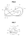
- FIG. 7 is an explanatory diagram showing a scene where an operator is inserting an insertion member to a patient with the operator and other things seen from overhead;
- FIG. 8 is an explanatory diagram showing another structure of an endoscope container for high-pressure steam sterilization in accordance with a third embodiment of the present invention.
- a first embodiment of the present invention will be described with reference to FIG. 1 to FIG. 3B .
- an endoscope system 1 in which the present embodiment is employed consists mainly of an electronic endoscope (hereinafter simply an endoscope) 2 , a light source apparatus 3 , a video processor 4 , and a monitor 5 .
- the endoscope 2 has an imaging means.
- the light source apparatus 3 supplies illumination light to the endoscope 2 .
- the video processor 4 controls the imaging means, and processes an image signal produced by the imaging means to produce, for example, a video signal.
- the video processor 4 is connected to the monitor 5 .
- a sterilization casing 50 that will be described later is an endoscope container for high-pressure steam sterilization in which the endoscope 2 is stowed.
- the endoscope 2 consists mainly of an insertion member 10 , a control section 11 , and a universal cord 12 .
- the insertion member 10 is elongated and flexible.
- the control section 11 is coupled to the proximal end of the insertion member 10 .
- the universal cord 12 is flexible and extended from the lateral part of the control section 11 .
- a connector 12 a that can be freely connected to or disconnected from the light source apparatus 3 is fixed to an end of the universal cord 12 .
- illumination light emanating from a lamp (not shown) that is incorporated in the light source apparatus 3 is propagated to a light guide (not shown) and runs through the endoscope 2 . A region to be observed is thus illuminated.
- An anti-breakage member 7 a for an insertion member formed with an elastic member is mounted on a joint between the insertion member 10 and control section 11 in order to prevent abrupt bending.
- an anti-breakage member 7 b for a control member analogous to the anti-breakage member 7 a for an insertion member is mounted on a joint between the control section 11 and universal cord 12 .
- an anti-breakage member 7 c for a connector analogous to the anti-breakage member 7 a for an insertion member is mounted on a joint between the universal cord 12 and connector 12 a.
- the insertion member 10 of the endoscope 2 that is elongated and flexible has a distal rigid part 13 , a bending section 14 , and a flexible tube 15 , which is a soft part, coupled to one another in that order from the distal end of the insertion member.
- the distal rigid part 13 is formed with a hard member.
- An observation window and an illumination window are formed in, for example, the distal surface of the distal rigid part 13 . Otherwise, an aeration/perfusion nozzle from which cleaning fluid or gas is jetted out towards the observation window, and a suction port through which a humor or filth is sucked are exposed on the distal surface of the distal rigid part 13 .
- the bending section 14 has a plurality of bending pieces (not shown) concatenated so that the bending section 14 can be bent freely.
- the flexible tube 15 is soft and resilient and has delicate properties.
- An angling knob 16 is formed on the control section 11 .
- the bending section 14 is bent in desired directions.
- the distal surface of the distal rigid part 13 having the observation window formed therein is angled in desired directions.
- an aeration/perfusion button 17 In addition to the angling knob 16 , an aeration/perfusion button 17 , a suction button 18 , a plurality of remote control switches 19 , and a therapeutic accessory insertion port 20 are formed on the control section 11 .
- the aeration/perfusion button 17 By pressing the aeration/perfusion button 17 , cleaning liquid or gas is jetted out from the aeration/perfusion nozzle. By pressing the suction button 18 , a humor etc. can be sucked through the suction port.
- the plurality of remote control switches 19 is used to remotely control, for example, the video processor 4 .
- the therapeutic accessory insertion port 20 communicates with a therapeutic accessory channel tube that will be described later and that runs through the insertion member of the endoscope 2 .
- An electric connector member 12 b is formed on the lateral part of the connector 12 a.
- a signal connector 6 a fixed to a signal cord 6 that is coupled to the video processor 4 is joined with the electric connector member 12 b so that the signal connector 6 a can be freely connected or disconnected.
- the signal connector 6 a is coupled to the video processor 4 , whereby the imaging means in the endoscope 2 is controlled by the video processor. Moreover, an image signal sent from the imaging means is processed in order to produce a video signal. Consequently, an endoscopic view image is displayed on the screen of the monitor 5 .
- the electric connector member 12 b has an air vent hole that is not shown and that links the interior and exterior of the endoscope 2 . Therefore, a pressure regulating valve-inclusive waterproof cap (hereinafter simply a waterproof cap) 9 a having a pressure regulating valve (not shown) that blocks the air vent hole can be freely detachably attached to the electric connector member 12 b of the endoscope 2 .
- the connector 12 a has a gas supply base 12 c, a water supply tank pressurization base 12 d, a fluid supply base 12 e, a suction base 12 f, an injection base 12 g, and a ground base 12 h formed thereon.
- the gas supply base 12 c is freely connected and disconnected to/from a gas source (not shown) that is incorporated in the light source apparatus 3 (not shown).
- the water supply tank pressurization base 12 d and liquid supply base 12 e are connected to a water tank 8 , which is a liquid source, so that they can be connected and disconnected freely.
- the suction base 12 f is connected to a sucking device (not shown) to suck fluid through the suction port.
- the injection base 12 g is connected to a water supplying device (not shown) that supplies water.
- An electric cable is plugged in to the ground base 12 h, whereby high-frequency leakage current generated during diathermy is fed back to a diathermy device (not shown).
- the endoscope 2 can be cleaned after being used for observation or treatment.
- the endoscope 2 can then be sterilized with high-pressure steam.
- the waterproof cap 9 a is attached to the electric connector member 12 b.
- the endoscope 2 is stowed in the sterilization casing 50 .
- the sterilization casing 50 consists mainly of a tray 51 that serves as a housing and a lid member 52 that blocks the opening of the tray 51 .
- the tray 51 has a positioning member that is shaped in conformity with the shape of the endoscope. The positioning member restricts the locations of the components of the endoscope 2 so that the insertion member 10 , control section 11 , universal cord 12 , and connector 12 a of the endoscope 2 will be settled in predetermined places.
- the tray 51 and lid member 52 each have a plurality of pores through which high-pressure steam is led in to the casing. When the lid member 52 is closed to meet the tray 51 , the interior of the casing is by no means airtight.
- the sterilization casing 50 has a tray body 53 that composes the tray 51 .
- the tray body 53 is attached by the lid member 52 that can be opened or closed freely and is composed of an inner lid 52 a shaped like a thin plate and an outer lid 52 b serving as a housing.
- the inner lid 52 a and outer lid 52 b are hinged to opposed sides of the tray body 52 to open in opposite directions.
- the lid member 52 has the inner lid 52 a and outer lid 52 b closed in that order. Even when an attempt is made to close the outer lid 52 b and inner lid 52 a in that order, the lids will not be closed.
- the flexible tube 15 of the endoscope 2 is available in various lengths.
- the present embodiment is concerned with the flexible tube 15 of a long type.
- the flexible tube of a long type is adopted, unless the insertion member 10 and universal cord 12 are bent, the endoscope cannot be settled in a relatively small high-pressure steam sterilizer that sterilizes the endoscope 2 .
- the tray body 53 has concave parts 53 a, 53 b, and 53 c that constitute a positioning member which enables the control section 11 , the connector 12 a, and the predetermined portion of the insertion member 10 to settle into predetermined places.
- the control section 11 , the connector 12 a, and the distal rigid part 13 of the insertion member 10 are settled into the concave parts 53 a, 53 b, and 53 c that are the predetermined places. Consequently, the bent states of the universal cord 12 and insertion member 10 , that is, the stowed states thereof are determined as shown in FIG. 2 .
- the tray body 53 has the concave control-section part 53 a, the concave connector part 53 b, the concave predetermined-portion part 53 c, a stowage 53 d, and a small-articles stowage 53 e.
- the concave control-section part 53 a provides a stowage for the control section 11 and is part a positioning member which restricts the location of the control section 11 .
- the concave connector part 53 b provides a stowage for the connector 12 a and is part of the positioning member which restricts the location of the connector 12 a.
- the concave predetermined-portion part 53 c provides a stowage for the predetermined portion of the insertion member 10 including the distal rigid part 13 and is part of the positioning member which restricts the location of the predetermined portion.
- the stowage 53 d is a place in which the universal cord 12 of the endoscope 2 and the portion of the insertion member 10 other than the predetermined portion thereof are stowed.
- the small-articles stowage 53 e is a place in which small articles such as the aeration/perfusion operation button 17 that was removed from the endoscope 2 , the suction button 18 , including a therapeutic accessory plug 31 that has been attached to the therapeutic accessory insertion port 20 , are stowed.
- the predetermined portion of the insertion member is a portion that dominates the inserting smoothness thereof.
- the predetermined portion of the insertion member includes the distal rigid part 13 , the bending section 14 , or the distal portion of the flexible tube 15 .
- the flexible tube 15 of the endoscope is as long as, for example, 133 cm or 168 cm.
- the length of the inserted portion of the insertion member is approximately 70 cm.
- the distal portion of 70 cm long of the insertion member is inserted to almost all patients.
- the inserted portion of approximately 70 cm long of the insertion member is the predetermined portion including a portion of the soft part.
- the concave parts 53 a, 53 b, 53 c, and 53 d of the tray body 53 are formed so that the predetermined portion of the insertion member will be stowed in a substantially straight form or a quite loosely bent form that is close to the straight form, that is, in a curved form that exhibits a large bend radius.
- a point of arrow A indicated in FIG. 2 is a point located approximately 70 cm away from the distal end of the distal rigid part 13 .
- the concave parts 53 a, 53 b, and 53 c have dimensions larger than the outer dimensions of the control section 11 , connector 12 a, distal rigid part 13 , bending section 14 , and flexible tube 15 so that a predetermined clearance will be preserved in each of the concave parts.
- the clearances in the concave parts are determined so that the control section 11 , the connector 12 a, the distal rigid part 13 , bending section 14 , and the distal portion of the flexible tube 15 will not move largely, can be mounted or dismounted easily, and will be fully exposed to high-pressure steam.
- the depths of the concave parts 53 a, 53 b, and 53 d are determined so that the control section 11 , connector 12 a, insertion member 10 , and universal cord 12 will not jut out of the top of the tray body 53 .
- the angling knob 16 juts out of the top of the tray body 53 . All the portions of the control section 11 except the angling knob 16 , the connector 12 a, the distal rigid part 13 , the bending section 14 , the flexible tube 15 , and the universal cord are fully settled in the concave parts 53 a, 53 b, 53 c, and 53 d.
- the concave parts 53 a and 53 b are shaped to have the clearances preserved so that an attempt of stowing the endoscope 2 in the tray body 53 with the aeration/perfusion button 17 , suction button 18 , and therapeutic accessory plug 31 attached to the endoscope 2 will fail.
- the aeration/perfusion button 17 , suction button 18 , and therapeutic accessory plug 31 are freely attachable and detachable to/from the endoscope 2 .
- the inner lid 52 a shaped like a thin plate and included in the sterilization casing 50 has a notch 52 c.
- the inner lid 52 a is closed to cover the top of the tray body 53 , the concave parts 53 a, 53 b, 53 c, 53 d, and 53 e are hidden behind the inner lid 52 a. In this state, the angling operation knob 16 juts out through the notch 52 c.
- the insertion member 10 , control section 11 , and universal cord 12 of the endoscope 2 are positioned and stowed with the predetermined clearances preserved.
- the insertion member 10 , control section 11 , and universal cord 12 will not be abutted on anything other than the tray body 53 and inner lid 52 a.
- a therapeutic accessory 32 and a cleaning tool 33 can be placed on the inner lid 52 a.
- the inner lid 52 a is formed with a transparent member and may be colored.
- the outer lid 52 b of the sterilization casing 50 that serves as a housing has a dent 52 d formed as an inner space that accommodates the therapeutic accessory 32 and cleaning tool 33 .
- a handle 34 and a grip 35 are formed on the outer edge of the tray body 53 .
- the handle 34 is grabbed by the hand in order to carry the sterilization casing 50 , for example, lengthwise.
- the grip 35 is used to hold the sterilization casing 50 , for example, horizontally.
- the conditions are stipulated in the U.S. standard ANSI/AAMI ST37-1992 approved by the American National Standards Institute (ANSI) and published from the Association for the Advancement of Medical Instrumentation (AAMI).
- the U.S. standard stipulates that a pre-vacuum sterilization process should be performed at 132° C. for four min, and that a gravity settling sterilization process should be performed at 132° C. for ten min.
- the condition of the temperature for high-pressure steam sterilization varies depending on the type of high-pressure steam sterilizer or the time required for sterilization. In general, the temperature ranges from about 115° C. to about 138° C. However, some sterilizers can be set to about 142° C.
- the condition of the time varies depending on the condition of the temperature for sterilization. In general, the time ranges from about 3 min to about 60 min. Some types of sterilizers can be set to about 100 min.
- the pressure in a sterilization chamber is set to a value that is higher by about 0.2 MPa than the atmospheric pressure.
- the waterproof cap 9 a is attached to the electric connector member 12 b of the endoscope 2 that is an apparatus to be sterilized. Thereafter, the endoscope 2 is stowed in the sterilization casing 50 with the portions thereof settled in the concave parts 53 a, 53 b, 53 c, and 53 d of the tray body 53 .
- the aeration/perfusion button 17 , suction button 18 , and therapeutic accessory plug 31 are stowed in the small-articles stowage 53 e.
- the tray body 53 is covered with the inner lid 52 a.
- the therapeutic accessory 32 and cleaning tool 33 are placed on the inner lid 52 a that covers the tray body 53 .
- the outer lid 52 b is closed to meet the tray body as shown in FIG. 3B .
- the sterilization casing 50 is then placed in a sterilizer. Prior to high-pressure sterilization, a sterilization chamber is decompressed (at a pre-vacuum step).
- the waterproof cap 9 a is attached to the electric connector member 12 b, the pressure regulating valve is closed and the air vent hole is blocked. In other words, the interior of the endoscope 2 is shut out from the exterior thereof and sealed to be watertight.
- the pre-vacuum step is a step of making preparations for infiltration of steam to every part of the apparatus to be sterilized at a sterilization step.
- the sterilization chamber is decompressed at the pre-vacuum step, whereby high-pressure high-temperature steam permeates the entire apparatus to be sterilized.
- the pressure in the sterilization chamber is generally set to a value that is smaller by a value ranging about 0.07 MPa to about 0.09 MPa than the atmospheric pressure.
- the sterilization chamber is pressurized. Consequently, a difference in pressure occurs between the interior and exterior of the endoscope 2 , that is, the external pressure of the endoscope 2 gets higher than the internal pressure thereof. This causes the pressure regulating valve of the waterproof cap 9 a to close. Eventually, high-pressure steam is disabled from invading into the endoscope through the air vent hole.
- high-pressure steam invades into the sterilization casing 50 through the pluralities of pores formed in the tray body 53 and in the inner lid 52 a and outer lid 52 b respectively that constitute the lid member 52 .
- the high-pressure steam then invades gradually into the endoscope through a sheathing tube 15 c of the flexible tube 15 or O rings (not shown).
- the sheathing tube 15 c is a housing member of the endoscope 2 and is made of a high polymer material.
- the O rings are made of fluorocarbon rubber or silicon rubber and serve as a sealing means included in the sheathing tube 15 c and joints of housing members of the endoscope 2 .
- the pressure is equivalent to the sum of pressure released during decompression at the pre-vacuum step and pressure added at the sterilization step.
- the sterilization chamber is decompressed again in order to dry the apparatus (dry step) that has been sterilized.
- the sterilization chamber is decompressed in order to remove steam from the sterilization chamber. This facilitates drying of the endoscope 2 .
- the pressure in the sterilization chamber is set to a value that is smaller by a value ranging from about 0.07 to about 0.09 MPa than the atmospheric pressure. The dry step is followed arbitrarily when needed.
- the pressure in the sterilization chamber is decreased. Consequently, a difference in pressure occurs between the interior and exterior of the endoscope 2 , that is, the external pressure of the endoscope 2 gets lower than the internal pressure thereof.
- the pressure regulating valve of the waterproof cap 9 a opens substantially at the same time.
- the interior and exterior of the endoscope 2 communicate with each other through the air vent hole. This prevents occurrence of a large difference in pressure between the interior and exterior of the endoscope.
- the sterilization chamber is pressurized.
- a difference in pressure occurs between the interior and exterior of the endoscope 2 , that is, the external pressure of the endoscope 2 gets higher than the internal pressure thereof. This causes the pressure regulating valve of the waterproof cap 9 a to close.
- the interior and exterior of the endoscope 2 are exposed to high-pressure steam.
- the predetermined portion of the endoscope 2 that includes the distal portion of the flexible tube 15 will not be held bent, though it is exposed to high-pressure steam. This is because the predetermined portion of the endoscope 2 of approximately 70 cm long away from the distal end of the distal rigid part 13 is stowed in a substantially straight form in the sterilization casing 50 .
- the predetermined portion of the flexible tube 15 that largely affects the inserting smoothness of the insertion member is prevented from being held bent.
- the positioning member including the concave control-section part, concave connector part, and concave predetermined-portion part is formed as an integral part of the tray body that forms the sterilization casing.
- the positioning member restricts the stowed state of the predetermined portion including the distal portion of the flexible tube that is the soft part to the substantially straight form.
- the stowed state of the predetermined portion of the insertion member including the distal portion of the flexible tube largely affects the inserting smoothness of the insertion member.
- the predetermined portion of the insertion member having the soft part is settled in the straight form. Therefore, after the endoscope is sterilized with high-pressure steam, the predetermined portion of the insertion member the soft part will not be held bent. This means that the inserting smoothness of the insertion member will not change despite high-pressure steam sterilization.
- the predetermined portion of 70 cm long away from the distal portion of the insertion member is stowed in a substantially straight form. If a high-pressure steam sterilizer has a sufficient space, the length of the distal portion of the insertion member that is stowed in the straight form may be larger than 70 cm.
- a sterilization casing 50 A in accordance with the present embodiment consists mainly of a tray body 53 A, an inner lid 55 a, and an outer lid 55 b.
- the inner lid 55 a is hinged to one side of the tray body 53 A and freely opened or closed as indicated with an alternate long and two short dashes line.
- the outer lid 55 b is freely opened or closed as indicated with an alternate long and two short dashes line.
- a concave control-section part 53 a, a concave universal-cord part 53 f, a concave connector part 53 b, a small-articles stowage 53 e, and a therapeutic accessory stowage 53 g are formed as integral parts of the tray body 53 A.
- the control section 11 , universal cord 12 , and connector 12 a of the endoscope 2 are settled in the concave control-section part 53 a, concave universal-cord part 53 f, and concave connector part 53 b respectively.
- the aeration/perfusion button 17 , the suction button 18 , the therapeutic accessory plug 31 , and a cleaning brush 36 are settled in the small-articles stowage 53 e.
- Therapeutic accessories 32 a and 32 b are settled in the therapeutic accessory stowage 53 g.
- the inner lid 55 a and outer lid 55 b hinge on the same side of the tray body 53 to open in the same direction.
- the inner lid 55 a covers part of the top of the tray body 53 A defined with a solid bold line in FIG. 4 .
- the concave parts 53 e, 53 f, and 53 g and part of the concave connector part 53 b are hidden behind the inner lid 55 a.
- the universal cord 12 and connector 12 a of the endoscope 2 are positioned with predetermined clearances preserved in concave parts but are not abutted on anything other than the tray body 53 A and inner lid 55 a.
- the insertion member 10 is placed on the tray body 53 A with a majority thereof jutted out of the tray body 53 A.
- the inner lid 55 a is closed. Consequently, the concave parts 53 e, 53 f, and 53 g and part of the concave connector part 53 b are hidden behind the inner lid 55 a.
- the insertion member 10 jutting out of the tray body 53 A is placed along a curved wall 56 formed on the top of the inner lid 55 a.
- the curved wall 56 is the positioning member and exhibits a bend radius of a predetermined value. Consequently, the distal portion of the soft part of the insertion member 10 is quite loosely bent.
- the bend radius of the curved wall 56 is set larger than a bend radius of the proximal portion of the insertion member.
- the inner lid 55 a is, as shown in FIG. 5B , engaged with a step portion 54 of the tray body 53 . Therefore, the top of the lid 55 a and the top of the tray body 53 A lie substantially on the same plane. The flexible tube 15 included in the insertion member 10 will therefore pass no step when being led from the tray body 53 A to the inner lid 55 a.
- the curved wall 56 forms a distal portion-of-insertion member placement section 56 a in which the distal rigid part 13 and bending section 14 of the insertion member 10 are placed with a predetermined clearance preserved in the placement section.
- the flexible tube 15 is settled along the curved wall 56 .
- the height of the curved wall 56 is, as shown in FIG. 5C , larger than the diameter of the flexible tube 15 .
- the insertion member 10 , universal cord 12 , and connector 12 a are positioned three-dimensionally in the sterilization casing 50 A with the insertion member 10 separated from the universal cord 12 and connector 12 a with the inner lid 55 a between them.
- An arrow A in FIG. 5A indicates a point apart by approximately 70 cm away from the distal end. According to the present embodiment, the distal portion of 70 cm long of the insertion member 10 is settled while being quite loosely bent.
- the other components of the present embodiment and an operation thereof are identical to those of the first embodiment. The same reference numerals are assigned to the same members, and the description of the members is omitted.
- the insertion member, universal cord, and connector are positioned three-dimensionally within the sterilization casing while the insertion member of the endoscope is separated from the universal cord and connector thereof with the inner lid between them. This results in the compact sterilization casing.
- the bend radius of the distal portion of 70 cm long of the insertion member is set larger than the bend radius of the proximal portion of the flexible tube that is proximal from the distal portion of 70 cm long. Even if the flexible tube may be held bent a little after being sterilized with high-pressure steam, the substantial inserting smoothness of the insertion member can be retained at a very high level.
- the other operation and advantage are identical to those of the first embodiment.
- the structure of the tray body will not be detailed.
- the tray body may be structured so that the endoscope 2 will be stowed as shown in FIG. 6 .
- the insertion member 10 is bent along the universal cord 12 that is extended from the control section 11 .
- the insertion member 10 is bent in a direction different from a direction in which the universal cord 12 extends. The predetermined portion of the insertion member including a portion of the flexible tube 15 is settled this way.
- the predetermined portion is settled in a substantially straight form in the direction of a diagonal of the rectangular tray 51 , that is, in a direction not parallel with any side of the rectangular tray 51 . Consequently, the longer part of 70 cm away from the end of the distal portion of the insertion member can be settled in the substantially straight form.
- the predetermined portion of the insertion member is settled along the longest possible straight line by using effectively the most of the space in the tray 51 .
- the endoscope 2 is angled in, normally, four directions, that is, in up, down, right, and left directions.
- the angling knob 16 is manipulated, if the endoscope appears to move upwards on the screen of the monitor 5 , the endoscope is said to be angled in the up direction.
- the other three directions are determined with respect to the up direction.
- the flexible tube 15 is bent in the up direction.
- an operator 60 usually holds, as shown in FIG. 7 , the control section 11 with the left hand and holds part of the flexible tube 15 with the right hand.
- the flexible tube 15 is so long that the proximal portion of the flexible tube 15 is often bent, though the magnitude of bend varies depending on the operator 60 .
- the flexible tube is bent in a direction close to the up direction.
- the portion of the flexible tube proximal to the predetermined portion of the insertion member is held bent in consideration of a direction in which the flexible tube is always bent during examination. Therefore, even if the portion of the flexible tube proximal to the predetermined portion of the insertion member is held bent, an operator will not feel that the inserting smoothness of the insertion member has changed.
- the predetermined portion of the insertion member is settled in the direction of a diagonal of the rectangular tray and is thus substantially straightened.
- the distal portion of 70 cm or longer of the insertion member can be settled in a substantially straight form, and the sterilization casing can be designed compactly.
- the insertion member 10 is always bent in the same direction. After the endoscope is sterilized repeatedly with high-pressure steam, the insertion member 10 may be held bent to a greater extent.
- tray bodies causing the insertion member to bend in opposite directions may be made available in order to prevent the insertion member from being held bent in one direction. In this case, even after the endoscope is sterilized repeatedly with high-pressure steam, the initial inserting smoothness thereof can be maintained.
- the direction in which the insertion member is bent is not limited to the up or down direction but may be the right or left direction.
- a third embodiment of the present invention will be described with reference to FIG. 8 .
- An endoscope container for high-pressure steam sterilization in accordance with the present embodiment is a substantially tubular insertion member sheathing member 70 that can be freely attached and detached to/from the insertion member 10 of the endoscope 2 .
- the insertion member sheathing member 70 consists mainly of a hard pipe portion 71 , a coil pipe portion 72 , and a fixing member 73 .
- the hard pipe portion 71 is part of the positioning member and is formed with a relatively hard member.
- the hard pipe portion 71 sheathes and holds the distal portion of 70 cm long of the insertion member 10 of the endoscope 2 , that is, the predetermined portion of the insertion member 10 thereof in a predetermined form (substantially straight form).
- arrow A indicates a point of 70 cm apart from the distal end of the insertion member 10 .
- the coil pipe portion 72 that is flexible sheathes the portion of flexible tube 15 proximal from the distal portion of 70 cm long of the insertion member 10 .
- the flexible tube 15 is a soft part of the insertion member 10 .
- the fixing member 73 is fixed to the proximal end of the coil pipe portion 72 .
- the fixing member 73 is located, for example, at the position of the therapeutic accessory insertion port 20 formed in the control section 1 . Consequently, the insertion member sheathing member 70 is attached to the insertion member 10 as an integral part of the insertion member 10 , thus sheathing the insertion member 10 .
- the thus structured insertion member sheathing member 70 is attached to the insertion member 10 of the endoscope 2 before the endoscope 2 that has been used is sterilized with high-pressure steam.
- the endoscope 2 With the insertion member sheathing member 70 thus attached, the endoscope 2 is placed in a sterilizer or the tray 51 .
- the flexible tube 15 of the endoscope 2 is bent, the endoscope 2 cannot be stowed in the tray 51 or a high-pressure steam sterilizer.
- the portion of the insertion member sheathed with the coil pipe portion 72 of the insertion member sheathing member 70 is therefore bent.
- the predetermined portion of the insertion member sheathed with the hard pipe portion 71 is hardly bent but held straight.
- the insertion member sheathing member that sheathes the insertion member is composed of the hard pipe portion that sheathes the predetermined portion and the coil pipe portion that sheathes the proximal portion of the flexible tube.
Landscapes
- Health & Medical Sciences (AREA)
- Epidemiology (AREA)
- Life Sciences & Earth Sciences (AREA)
- Animal Behavior & Ethology (AREA)
- General Health & Medical Sciences (AREA)
- Public Health (AREA)
- Veterinary Medicine (AREA)
- Apparatus For Disinfection Or Sterilisation (AREA)
- Endoscopes (AREA)
Abstract
Description
Claims (16)
Applications Claiming Priority (2)
| Application Number | Priority Date | Filing Date | Title |
|---|---|---|---|
| JP2000237312A JP3833879B2 (en) | 2000-08-04 | 2000-08-04 | Endoscope device |
| JP2000-237312 | 2000-08-04 |
Publications (2)
| Publication Number | Publication Date |
|---|---|
| US20020015673A1 US20020015673A1 (en) | 2002-02-07 |
| US7303734B2 true US7303734B2 (en) | 2007-12-04 |
Family
ID=18729196
Family Applications (1)
| Application Number | Title | Priority Date | Filing Date |
|---|---|---|---|
| US09/919,190 Expired - Fee Related US7303734B2 (en) | 2000-08-04 | 2001-07-31 | Endoscope container for high-pressure steam sterilization |
Country Status (2)
| Country | Link |
|---|---|
| US (1) | US7303734B2 (en) |
| JP (1) | JP3833879B2 (en) |
Cited By (4)
| Publication number | Priority date | Publication date | Assignee | Title |
|---|---|---|---|---|
| US8235209B2 (en) | 2010-08-11 | 2012-08-07 | Boston Scientific Scimed, Inc. | Medical device packaging and methods for preparing and packaging medical devices |
| US8973748B2 (en) | 2011-01-19 | 2015-03-10 | Boston Scientific Scime, Inc. | Medical device packaging and methods for preparing and packaging medical devices |
| US9096368B2 (en) | 2011-01-19 | 2015-08-04 | Boston Scientific Scimed, Inc. | Medical device packaging and methods for preparing and packaging medical devices |
| US20150320896A1 (en) * | 2014-05-06 | 2015-11-12 | American Sterilizer Company | Sterilizer |
Families Citing this family (15)
| Publication number | Priority date | Publication date | Assignee | Title |
|---|---|---|---|---|
| JP3905320B2 (en) * | 2001-02-28 | 2007-04-18 | オリンパス株式会社 | Endoscopic high-temperature high-pressure steam sterilization container and endoscope cleaning and sterilization system |
| JP3831276B2 (en) * | 2002-02-27 | 2006-10-11 | オリンパス株式会社 | Endoscope autoclave device |
| US6884392B2 (en) * | 2002-11-12 | 2005-04-26 | Minntech Corporation | Apparatus and method for steam reprocessing flexible endoscopes |
| KR100845079B1 (en) * | 2003-07-22 | 2008-07-09 | 올림푸스 가부시키가이샤 | High temperature and high pressure steam sterilization method for endoscope, and endoscope |
| JP4414734B2 (en) * | 2003-11-12 | 2010-02-10 | オリンパス株式会社 | Endoscope system |
| JP4733927B2 (en) * | 2004-03-25 | 2011-07-27 | オリンパス株式会社 | Endoscope storage case and endoscope apparatus |
| JP2006068330A (en) * | 2004-09-02 | 2006-03-16 | Pentax Corp | Endoscope sterilization method |
| US10058342B2 (en) * | 2006-01-12 | 2018-08-28 | Gynesonics, Inc. | Devices and methods for treatment of tissue |
| JP5243726B2 (en) * | 2007-03-30 | 2013-07-24 | 日立コンシューマエレクトロニクス株式会社 | Motor function measuring device |
| JP6022317B2 (en) * | 2012-11-19 | 2016-11-09 | 株式会社Ihiシバウラ | Endoscope cleaning device |
| JP6411852B2 (en) * | 2014-10-07 | 2018-10-24 | 平田機工株式会社 | Conveying device, conveying system, and conveying method |
| US10814027B2 (en) | 2017-12-07 | 2020-10-27 | Asp Global Manufacturing Gmbh | Sterilization-assistance device |
| US10967084B2 (en) | 2017-12-15 | 2021-04-06 | Asp Global Manufacturing Gmbh | Flow restrictor |
| US20190201568A1 (en) * | 2017-12-29 | 2019-07-04 | Ethicon, Inc. | Sterilization tray |
| CN109349828A (en) * | 2018-11-09 | 2019-02-19 | 安徽爱就爱家具制造有限公司 | A kind of table ware cabinet |
Citations (8)
| Publication number | Priority date | Publication date | Assignee | Title |
|---|---|---|---|---|
| US3633758A (en) * | 1970-01-09 | 1972-01-11 | North American Instr Corp | Catheter storage rack |
| JPH05285103A (en) | 1992-04-10 | 1993-11-02 | Olympus Optical Co Ltd | Autoclave device for endoscope |
| JPH0663007A (en) | 1992-08-14 | 1994-03-08 | Olympus Optical Co Ltd | Protective body of curving part |
| US5534221A (en) * | 1992-03-13 | 1996-07-09 | American Sterilizer Company | Device and system for sterilizing objects |
| US5759490A (en) * | 1996-06-14 | 1998-06-02 | Steris Corporation | Porous clip for concurrent catheter sterilization and reshaping |
| US5882589A (en) * | 1994-06-03 | 1999-03-16 | Leon Shipper | Sealed endoscope decontamination, disinfection and drying device |
| JP2000060791A (en) * | 1998-08-26 | 2000-02-29 | Olympus Optical Co Ltd | Endoscope tray |
| US6361751B1 (en) * | 1999-11-01 | 2002-03-26 | Next Step Medical Technologies L.L.C. | Apparatus and method for disinfecting an endoscope |
Family Cites Families (3)
| Publication number | Priority date | Publication date | Assignee | Title |
|---|---|---|---|---|
| JPS6395045A (en) * | 1986-10-08 | 1988-04-26 | オリンパス光学工業株式会社 | Protector of medical instrument |
| JPH04806Y2 (en) * | 1987-01-28 | 1992-01-13 | ||
| JP3869060B2 (en) * | 1996-12-24 | 2007-01-17 | オリンパス株式会社 | Endoscope |
-
2000
- 2000-08-04 JP JP2000237312A patent/JP3833879B2/en not_active Expired - Fee Related
-
2001
- 2001-07-31 US US09/919,190 patent/US7303734B2/en not_active Expired - Fee Related
Patent Citations (8)
| Publication number | Priority date | Publication date | Assignee | Title |
|---|---|---|---|---|
| US3633758A (en) * | 1970-01-09 | 1972-01-11 | North American Instr Corp | Catheter storage rack |
| US5534221A (en) * | 1992-03-13 | 1996-07-09 | American Sterilizer Company | Device and system for sterilizing objects |
| JPH05285103A (en) | 1992-04-10 | 1993-11-02 | Olympus Optical Co Ltd | Autoclave device for endoscope |
| JPH0663007A (en) | 1992-08-14 | 1994-03-08 | Olympus Optical Co Ltd | Protective body of curving part |
| US5882589A (en) * | 1994-06-03 | 1999-03-16 | Leon Shipper | Sealed endoscope decontamination, disinfection and drying device |
| US5759490A (en) * | 1996-06-14 | 1998-06-02 | Steris Corporation | Porous clip for concurrent catheter sterilization and reshaping |
| JP2000060791A (en) * | 1998-08-26 | 2000-02-29 | Olympus Optical Co Ltd | Endoscope tray |
| US6361751B1 (en) * | 1999-11-01 | 2002-03-26 | Next Step Medical Technologies L.L.C. | Apparatus and method for disinfecting an endoscope |
Cited By (5)
| Publication number | Priority date | Publication date | Assignee | Title |
|---|---|---|---|---|
| US8235209B2 (en) | 2010-08-11 | 2012-08-07 | Boston Scientific Scimed, Inc. | Medical device packaging and methods for preparing and packaging medical devices |
| US8973748B2 (en) | 2011-01-19 | 2015-03-10 | Boston Scientific Scime, Inc. | Medical device packaging and methods for preparing and packaging medical devices |
| US9096368B2 (en) | 2011-01-19 | 2015-08-04 | Boston Scientific Scimed, Inc. | Medical device packaging and methods for preparing and packaging medical devices |
| US20150320896A1 (en) * | 2014-05-06 | 2015-11-12 | American Sterilizer Company | Sterilizer |
| US9669119B2 (en) * | 2014-05-06 | 2017-06-06 | American Sterilizer Company | Sterilizer |
Also Published As
| Publication number | Publication date |
|---|---|
| JP2002045335A (en) | 2002-02-12 |
| JP3833879B2 (en) | 2006-10-18 |
| US20020015673A1 (en) | 2002-02-07 |
Similar Documents
| Publication | Publication Date | Title |
|---|---|---|
| US7303734B2 (en) | Endoscope container for high-pressure steam sterilization | |
| JP3905320B2 (en) | Endoscopic high-temperature high-pressure steam sterilization container and endoscope cleaning and sterilization system | |
| KR100685337B1 (en) | Endoscope flexible tube | |
| US6514198B2 (en) | Endoscope capable of undergoing at least one of cleaning, disinfection, and sterilization at high temperature | |
| US6916285B2 (en) | Endoscope device | |
| US6679835B2 (en) | Endoscope device | |
| US6730018B2 (en) | Endoscope | |
| US20200367732A1 (en) | Endoscope | |
| US6689052B2 (en) | Endoscope characterized by soft section thereof through which built-in components lie | |
| JP3790920B2 (en) | High temperature high pressure steam sterilization container | |
| US6773395B2 (en) | Endoscope | |
| US7850603B2 (en) | Endoscope for sterilizing built-in elongated channel with high-temperature and high-pressure vapor | |
| US6761686B2 (en) | Endoscope | |
| JP4678980B2 (en) | Endoscope cooling device | |
| US6565506B2 (en) | Endoscope | |
| JP3831276B2 (en) | Endoscope autoclave device | |
| JP2748330B2 (en) | Sheath device for rigid endoscope | |
| JP3691757B2 (en) | Autoclave equipment | |
| JPH06319677A (en) | Cover type endoscope | |
| JP2002330921A (en) | Endoscopic apparatus | |
| JP3402646B2 (en) | Endoscope with endoscope cover method | |
| JP2010201052A (en) | Endoscope |
Legal Events
| Date | Code | Title | Description |
|---|---|---|---|
| AS | Assignment |
Owner name: OLYMPUS OPTICAL CO., LTD., JAPAN Free format text: ASSIGNMENT OF ASSIGNORS INTEREST;ASSIGNOR:MORIYAMA, HIROKI;REEL/FRAME:012050/0415 Effective date: 20010717 |
|
| AS | Assignment |
Owner name: OLYMPUS CORPORATION, JAPAN Free format text: CHANGE OF NAME;ASSIGNOR:OLYMPUS OPTICAL CO., LTD.;REEL/FRAME:015995/0172 Effective date: 20031001 |
|
| STCF | Information on status: patent grant |
Free format text: PATENTED CASE |
|
| FPAY | Fee payment |
Year of fee payment: 4 |
|
| FPAY | Fee payment |
Year of fee payment: 8 |
|
| AS | Assignment |
Owner name: OLYMPUS CORPORATION, JAPAN Free format text: CHANGE OF ADDRESS;ASSIGNOR:OLYMPUS CORPORATION;REEL/FRAME:039344/0502 Effective date: 20160401 |
|
| FEPP | Fee payment procedure |
Free format text: MAINTENANCE FEE REMINDER MAILED (ORIGINAL EVENT CODE: REM.); ENTITY STATUS OF PATENT OWNER: LARGE ENTITY |
|
| LAPS | Lapse for failure to pay maintenance fees |
Free format text: PATENT EXPIRED FOR FAILURE TO PAY MAINTENANCE FEES (ORIGINAL EVENT CODE: EXP.); ENTITY STATUS OF PATENT OWNER: LARGE ENTITY |
|
| STCH | Information on status: patent discontinuation |
Free format text: PATENT EXPIRED DUE TO NONPAYMENT OF MAINTENANCE FEES UNDER 37 CFR 1.362 |
|
| FP | Lapsed due to failure to pay maintenance fee |
Effective date: 20191204 |