JP3807775B2 - How to lift the construction elevator - Google Patents
How to lift the construction elevator Download PDFInfo
- Publication number
- JP3807775B2 JP3807775B2 JP9714896A JP9714896A JP3807775B2 JP 3807775 B2 JP3807775 B2 JP 3807775B2 JP 9714896 A JP9714896 A JP 9714896A JP 9714896 A JP9714896 A JP 9714896A JP 3807775 B2 JP3807775 B2 JP 3807775B2
- Authority
- JP
- Japan
- Prior art keywords
- hoisting rope
- machine room
- counterweight
- car
- rope
- Prior art date
- Legal status (The legal status is an assumption and is not a legal conclusion. Google has not performed a legal analysis and makes no representation as to the accuracy of the status listed.)
- Expired - Fee Related
Links
Images


Description
【0001】
【発明の属する技術分野】
この発明は、建築工事が下層階から上層階へ進捗するに従って昇降行程が上方へ延長される工事用エレベーターの上昇移動方法に関する。
【0002】
【従来の技術】
図9〜図11は、例えば特開昭57−38283号公報に示された従来の工事用エレベーター装置に類似した工事用エレベーター装置を示す図で、図9は縦断面図、図10は図9の工事用エレベーター装置の上昇移動状態を示す図、図11は図9の工事用エレベーター装置の上昇移動後の状態を示す図である。図において、1は建物、2は建物1に設けられた昇降路で、上下に互いに離れて設置された梁からなる建築構造体3により横断面において区分されている。
【0003】
4は建築構造体3により区分された昇降路2の一側を昇降するかご、5は建築構造体3により区分された昇降路2の他側を昇降するつり合おもり、6は昇降路2のかご4の上方に仮設された移動機械室で、吊り具7及び駆動綱車8を有する巻上機9が設けられている。10は移動機械室6を支持する架台、11は架台10に設けられてつり合おもり5の上方に配置された滑車である。
【0004】
12は巻上ロープで、駆動綱車8及び滑車11に巻掛けられて一端はかご4に他端はつり合おもり5に連結されている。13は昇降路2の底部に設けられたかご衝突受、14は昇降路2の底部に設けられたつり合おもり衝突受、15は建物1の上部に設けられたクレーンで、16はそれのクレーンロープ、17は一端が移動機械室6の下部に他端はかご4に連結された揚重用鎖である。
【0005】
従来の工事用エレベーター装置は上記のように構成され、建築工事中の建物1に構成された昇降路2の上端部に移動機械室6が仮設される。そして、巻上ロープ12が駆動綱車8及び滑車11に巻掛けられて図9に示すようにかご4及びつり合おもり5が吊持される。この状態で巻上機9が付勢されると巻上ロープ12を介してかご4及びつり合おもり5が互いに反対方向へ運転される。
【0006】
これによって、建築された建物1の階床に対応した昇降路2による昇降行程におけるエレベーターの工事用運転が行われる。そして、建築工事が進捗して昇降路2が上方に延長されると、移動機械室6が延長された昇降路2の上端部に移動される。この移動機械室6の上方移動には次に述べる作業が行われる。
【0007】
すなわち、先ずつり合おもり5を昇降路2の最下部まで下げてつり合おもり衝突受14に支持する。次いで、かご4を揚重用鎖17によって移動機械室6に吊持して、かご4及びつり合おもり5から巻上ロープ12を外して撤去する。そして、クレーン15のクレーンロープ16を吊り具7に連結して移動機械室6を吊持する。次いで、架台10及び滑車11が撤去され、これにより図10に示す状態となる。
【0008】
次に、クレーン15により移動機械室6が延長された昇降路2の上端部に移動され、移動機械室6対応位置に架台10及び滑車11が再度仮設される。そして、巻上ロープ12によりかご4及びつり合おもり5が再度吊持されて、揚重用鎖17が撤去されて図11に示す状態となる。これにより、延長された建物1の階床に対応した昇降路2による昇降行程におけるエレベーターの工事用運転が行われる。そして、建築工事の進捗に伴って移動機械室6の上方移動が繰り返され、建築工事の進捗に対応した昇降行程によるエレベーターの工事用運転を行うようになっている。
【0009】
【発明が解決しようとする課題】
上記のような従来の工事用エレベーター装置において、かご4及びつり合おもり5の昇降経路が建築構造体3により区分されている。このため、巻上ロープ12が建築構造体3を跨いで吊設されるので、移動機械室6の上方移動の都度、かご4及びつり合おもり5を共に巻上ロープ12から外すことが必要となる。また、上方移動した移動機械室6の位置に対応した長さの巻上ロープ12が上方移動の度毎に掛け替えられる。このため、移動機械室6の上方移動に煩雑な作業を要するという問題点があった。
【0010】
この発明は、かかる問題点を解消するためになされたものであり、簡易な作業により、また少ない費用によって移動機械室の上方移動ができる工事用エレベーターの上昇移動方法及び工事用エレベーター装置を得ることを目的とする。
【0011】
【課題を解決するための手段】
この発明に係る工事用エレベーターの上昇移動方法においては、建物に設けられて横断面において建築構造体により区分された昇降路の一側を昇降するかご及び昇降路の他側を昇降するつり合おもりと、巻上機が設置されて昇降路のかごの上方に仮設された移動機械室と、巻上機の駆動綱車に巻掛けられて一端がつり合おもりに切離し自在に接続され他端はかごに配置された巻上ロープと、かごに設けられて巻上ロープのかご側の端部が巻き込まれ繰り出し自在に構成されて巻上ロープを所定長さにおいて固定する巻上ロープ繰出装置と、移動機械室に設けられて要時に巻上ロープを保持する巻上ロープ保持装置と、要時に移動機械室及びつり合いおもりに連結される揚重手段とを備え、 移動機械室を延長された昇降路の上端部に移動する際に、かごを昇降路の最下部まで下げ、かごが昇降しないようにするステップと、かごの巻上ロープ繰出装置のロープ保持を解除し、巻上ロープを繰出し可能状態にするステップと、巻上ロープ保持装置により巻上ロープを保持するステップと、つり合おもりに連結された巻上ロープを取外すステップと、建物の上部に設置されたクレーンにより、揚重手段を介して移動機械室及び巻上ロープから切離されたつり合いおもりを引上げ、移動機械室を延長された上方の階床に仮設するステップと、取外された巻上ロープをつり合おもりに連結するステップと、移動機械室の巻上ロープ保持装置の保持力を解除し、かごの巻上ロープ繰出装置により巻上ロープを保持するステップと、移動機械室及びつり合いおもりから揚重手段を撤去するステップと含むものである。
【0012】
また、建物に設けられて横断面において建築構造体により区分された昇降路の一側を昇降するかご及び昇降路の他側を昇降するつり合おもりと、巻上機が設置されて昇降路のかごの上方に仮設された移動機械室と、巻上機の駆動綱車に巻掛けられて一端がつり合おもりに切離し自在に接続され他端はかごに配置された巻上ロープと、かごに設けられて巻上ロープのかご側の端部が巻き込まれ繰り出し自在に構成されて巻上ロープを所定長さにおいて固定する巻上ロープ繰出装置と、移動機械室に設けられて要時に巻上ロープを保持する巻上ロープ保持装置と、要時に移動機械室及びつり合いおもりにそれぞれ連結される移動機械室揚重用ロープ及びつり合いおもり揚重用ロープとを備え、移動機械室を延長された昇降路の上端部に移動する際に、かごを昇降路の最下部まで下げ、かごが昇降しないようにするステップと、かごの巻上ロープ繰出装置のロープ保持を解除し、巻上ロープを繰出し可能状態にするステップと、巻上ロープ保持装置により巻上ロープを保持するステップと、つり合おもりに連結された巻上ロープを取外すステップと、建物の上部に設置されたクレーンにより、移動機械室揚重用ロープ及びつり合いおもり揚重用ロープを介して移動機械室及び巻上ロープから切離されたつり合いおもりを引上げ、移動機械室を延長された上方の階床に仮設するステップと、取外された巻上ロープをつり合おもりに連結するステップと、移動機械室の巻上ロープ保持装置の保持力を解除し、かごの巻上ロープ繰出装置により巻上ロープを保持するステップと、移動機械室及びつり合いおもりから移動機械室揚重用ロープ及びつり合いおもり揚重用ロープを撤去するステップと含むものである。
【0013】
また、建物に設けられて横断面において建築構造体により区分された昇降路の一側を昇降するかご及び昇降路の他側を昇降するつり合おもりと、巻上機が設置されて昇降路のかごの上方に仮設された移動機械室と、巻上機の駆動綱車に巻掛けられて一端がつり合おもりに切離し自在に接続され他端はかごに配置された巻上ロープと、かごに設けられて巻上ロープのかご側の端部が巻き込まれ繰り出し自在に構成されて巻上ロープを所定長さにおいて固定する巻上ロープ繰出装置と、移動機械室に設けられて要時に巻上ロープを保持する巻上ロープ保持装置と、要時に両端部がそれぞれつり合いおもり及び移動機械室に連結され、中間部が移動機械室位置よりも下方の昇降路の固定部に枢着された下部上昇移動滑車及び昇降路の最上部に枢着された上部上昇移動滑車に巻掛けられたつり合いおもり揚重用ロープとを備え、移動機械室を延長された昇降路の上端部に移動する際に、かごを昇降路の最下部まで下げ、かごが昇降しないようにするステップと、かごの巻上ロープ繰出装置のロープ保持を解除し、巻上ロープを繰出し可能状態にするステップと、巻上ロープ保持装置により巻上ロープを保持するステップと、つり合おもりに連結された巻上ロープを取外すステップと、建物の上部に設置されたクレーンにより、移動機械室を引上げることにより、この移動機械室に連結されたつり合いおもり揚重用ロープを介して、巻上ロープから切離されたつり合いおもりを引上げ、移動機械室を延長された上方の階床に仮設するステップと、取外された巻上ロープをつり合おもりに連結するステップと、移動機械室の巻上ロープ保持装置の保持力を解除し、かごの巻上ロープ繰出装置により巻上ロープを保持するステップと、移動機械室及びつり合いおもりに連結されたつり合いおもり用揚重ロープを撤去するステップと含むものである。
【0014】
【発明の実施の形態】
実施の形態1.
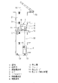
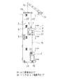
図1〜図4は、この発明の実施の形態の一例を示す図で、図1は縦断面図、図2は図1の工事用エレベーター装置の上昇移動状態を示す図、図3は図1の工事用エレベーター装置の上昇移動後の状態を示す図、図4は図1の工事用エレベーター装置の上昇移動の手順を説明する工程図である。図において、1は建物、2は建物1に設けられた昇降路で、上下に互いに離れて設置された梁からなる建築構造体3により横断面において区分されている。
【0015】
4は建築構造体3により区分された昇降路2の一側を昇降するかご、5は建築構造体3により区分された昇降路2の他側を昇降するつり合おもり、6は昇降路2のかご4の上方に仮設された移動機械室で、吊り具7及び駆動綱車8を有する巻上機9が設けられている。10は移動機械室6を支持する架台、11は架台10に設けられてつり合おもり5の上方に配置された滑車である。
【0016】
13は昇降路2の底部に設けられたかご衝突受、14は昇降路2の底部に設けられたつり合おもり衝突受、15は建物1の上部に設けられたクレーンで、16はそれのクレーンロープである。18は巻上ロープで、駆動綱車8及び滑車11に巻掛けられて一端はかご4に他端はつり合おもり5に連結されている。19はかご4に設けられて巻上ロープ18のかご4側の端部が巻き込まれ繰り出し自在に構成されて巻上ロープ18を所定長さにおいて固定する巻上ロープ繰出装置である。
【0017】
20はクレーンロープ16の下端に設けられた揚重具、21は両端がそれぞれ揚重具20及び移動機械室6の吊り具7に連結された移動機械室揚重用ロープ、22は両端がそれぞれ揚重具20及びつり合おもり5に連結されたつり合おもり揚重用ロープである。23は移動機械室6に設けられて要時に巻上ロープ18を保持する巻上ロープ保持装置である。
【0018】
上記のように構成された工事用エレベーター装置において、建築工事中の建物1に構成された昇降路2の上端部に移動機械室6が仮設される。そして、巻上ロープ18が駆動綱車8及び滑車11に巻掛けられて巻上ロープ繰出装置19を介してかご4に連結され、またつり合おもり5に連結されて図1に示す状態となる。そして、巻上機9が付勢されると巻上ロープ18を介してかご4及びつり合おもり5が互いに反対方向へ運転される。
【0019】
これによって、建築された建物1の階床に対応した昇降路2による昇降行程におけるエレベーターの工事用運転が行われる。そして、建築工事が進捗して昇降路2が上方に延長されると、移動機械室6が延長された昇降路2の上端部に移動される。この移動機械室6の上方移動作業手順を図4に示す工程図により説明する。
【0020】
すなわち、ステップ101によりかご4を昇降路2の最下部まで下げてかご衝突受13に支持して昇降しないようにする。次いでステップ102によりクレーンロープ16の揚重具20に、移動機械室揚重用ロープ21により移動機械室6を連結し、またつり合おもり揚重用ロープ22よりつり合おもりを連結する。そして、ステップ103へ進みかご4の巻上ロープ繰出装置19の巻上ロープ18保持を解除して巻上ロープ18を繰出し可能状態とする。
【0021】
次に、ステップ104へ進んで移動機械室6の巻上ロープ保持装置23により巻上ロープ18を保持し、移動機械室6からの巻上ロープ18の落下を防ぐ。そして、ステップ105によりつり合おもり5に連結された巻上ロープ18を外して移動機械室6内に引き込み、架台10及び滑車11が撤去されて図2に示す状況となる。次いで、ステップ106へ進みクレーン15によりつり合おもり5及び移動機械室6が引上げられる。
【0022】
そして、移動機械室6が延長された昇降路2の上端部の階床に移動され、移動機械室6対応位置に架台10及び滑車11が再度仮設される。次に、ステップ107へ進んで、移動機械室6内に引き込まれていた巻上ロープ18を繰出してつり合おもり5に連結する。そして、ステップ108により移動機械室6の巻上ロープ保持装置23による巻上ロープ18の保持を解除し、またかご4の巻上ロープ繰出装置19により巻上ロープ18を保持する。
【0023】
次いで、ステップ109へ進んで、クレーンロープ16の揚重具20、移動機械室揚重用ロープ21及びつり合おもり揚重用ロープ22を撤去して図3に示す状態となる。これにより、延長された建物1の階床に対応した昇降路2による昇降行程におけるエレベーターの工事用運転が行われる。そして、建築工事の進捗に伴って移動機械室6の上方移動が繰り返され、建築工事の進捗に対応した昇降行程によるエレベーターの工事用運転が行われる。
【0024】
要するに、建物1の上部に設けられたクレーン15によって、つり合おもり5が巻上ロープ18から切離された状態の移動機械室6及びつり合おもり5の少なくとも上方を経由するつり合おもり揚重用ロープ22を介して巻上ロープ18から切離された状態のつり合おもり5を揚重するものである。
【0025】
このような装置構成又は装置構成による工事用エレベーターの上昇移動方法によって、移動機械室6の上方移動に際してかご4とつり合おもり5のうち、つり合おもり5のみを巻上ロープ18から外すだけで済み作業を簡略化することができる。また、移動機械室6の最終上方移動位置に対応した長さの巻上ロープ18が巻上ロープ繰出装置19に収容される。このため、移動機械室6の上方移動の都度、所要長さを巻上ロープ繰出装置19から繰出すことにより対応できる。
【0026】
したがって、無駄な巻上ロープ18を準備することがなく、作業が簡易化すると共に、費用を低減することができる。
また、クレーン15によりつり合おもり5及び移動機械室6が同時に引上げられるので、建物側のクレーン15の使用時間を短縮することができる。
【0027】
また、揚重具20を介してつり合おもり5及び移動機械室6が引上げられる。このため、建築構造体3により移動機械室6側に比べて昇降路2の開口部が狭くなっているつり合おもり5側において、クレーン15のクレーンロープ16によりつり合おもり5を直接に揚重することがなく、クレーン15のクレーンロープ16を上方の開口部から昇降路2内に吊下する必要がない。したがって、クレーンロープ16を建築構造体3等の固定物に接触させて損傷する不具合を防ぐことができる。
【0028】
また、かご4を昇降路2の最下部に支持して巻上ロープ繰出装置19から巻上ロープ18を繰出すので、移動機械室6の引上げにより所要長さが自動的に繰出される。また、移動機械室6の上方移動の都度、新たに巻上ロープ18を手配する必要がなく、作業が容易にでき作業を能率化することができる。
【0029】
実施の形態2.
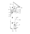
図5及び図6は、この発明の他の実施の形態の一例を示す図で、図5は工事用エレベーター装置の上昇移動状態を示す図であり前述の図2相当図、図6は図5の工事用エレベーター装置の上昇移動の手順を説明する工程図である。図において、図1〜図4と同符号は相当部分を示す。
【0030】
24は昇降路2最上部の建築構造体3の上側に枢着されてつり合おもり5の直上位置に配置された上部上昇移動滑車、25は移動機械室6の仮設位置よりも下方に配置された建築構造体3の下側に枢着された下部上昇移動滑車で、二つの滑車が回転軸線を互いに平行に、かつ互いに離れて配置されて構成されている。26は上部上昇移動滑車24及び下部上昇移動滑車25に巻掛けられて両端がそれぞれつり合おもり5及び移動機械室6の下部に連結されたつり合おもり揚重用ロープである。
【0031】
上記のように構成された工事用エレベーター装置において、前述の図1〜図4の工事用エレベーター装置と同様に、建築工事中の建物1に構成された昇降路2の上端部に移動機械室6が仮設される。そして、巻上ロープ18が駆動綱車8及び滑車11に巻掛けられて巻上ロープ繰出装置19を介してかご4に連結され、またつり合おもり5に連結されて図1に示す状態となる。そして、巻上機9が付勢されると巻上ロープ18を介してかご4及びつり合おもり5が互いに反対方向へ運転される。
【0032】
これによって、建築された建物1の階床に対応した昇降路2による昇降行程におけるエレベーターの工事用運転が行われる。そして、建築工事が進捗して昇降路2が上方に延長されると、移動機械室6が延長された昇降路2の上端部に移動される。この移動機械室6の上方移動作業手順を図6に示す工程図により説明する。
【0033】
すなわち、ステップ201により上部上昇移動滑車24及び下部上昇移動滑車25が設置される。そして、ステップ202によりかご4を昇降路2の最下部まで下げてかご衝突受13に支持して昇降しないようにする。次いでステップ203によりつり合おもり揚重用ロープ26を上部上昇移動滑車24及び下部上昇移動滑車25に巻掛けて両端をそれぞれつり合おもり5及び移動機械室6の下部に連結する。
【0034】
次いで、ステップ204へ進み、かご4の巻上ロープ繰出装置19の巻上ロープ18保持を解除して巻上ロープ18を繰出し可能状態とする。次に、ステップ205へ進んで移動機械室6の巻上ロープ保持装置23により巻上ロープ18を保持し、移動機械室6からの巻上ロープ18の落下を防ぐ。そして、ステップ206によりつり合おもり5に連結された巻上ロープ18を外して移動機械室6内に引き込み、架台10及び滑車11が撤去されて図5に示す状態となる。
【0035】
次いで、ステップ207へ進みクレーンロープ16を吊り具7に連結してクレーン15により移動機械室6を引上げる。これにより、つり合おもり5もつり合おもり揚重用ロープ26を介して引上げられる。そして、移動機械室6が延長された昇降路2の上端部の階床に移動され、移動機械室6対応位置に架台10及び滑車11が再度仮設される。
【0036】
次に、ステップ208へ進んで、移動機械室6内に引き込まれていた巻上ロープ18を繰出してつり合おもり5に連結する。そして、ステップ209により移動機械室6の巻上ロープ保持装置23による巻上ロープ18の保持を解除し、またかご4の巻上ロープ繰出装置19により巻上ロープ18を保持する。
【0037】
次いで、ステップ210へ進んで、つり合おもり揚重用ロープ26、上部上昇移動滑車24及び下部上昇移動滑車25が撤去される。これにより、延長された建物1の階床に対応した昇降路2による昇降行程におけるエレベーターの工事用運転が行われる。そして、建築工事の進捗に伴って移動機械室6の上方移動が繰り返され、建築工事の進捗に対応した昇降行程によるエレベーターの工事用運転が行われる。
【0038】
要するに、建物1の上部に設けられたクレーン15によって、つり合おもり5が巻上ロープ18から切離された状態の移動機械室6及びつり合おもり5の少なくとも上方を経由するつり合おもり揚重用ロープ26を介して巻上ロープ18から切離された状態のつり合おもり5を揚重するものである。
【0039】
したがって、詳細な説明を省略するが図5及び図6の実施の形態における装置構成又は装置構成による工事用エレベーターの上昇移動方法によって、前述の図1〜図4の実施の形態と同様な作用を得ることができる。
【0040】
また、図5及び図6の実施の形態において、移動機械室6の移動前の工事用エレベーターの運転に支障なく上部上昇移動滑車24を設置することができる。また、下部上昇移動滑車25は移動機械室6の上昇移動ごとに必ずしも撤去する必要はなく、移動機械室6の上昇移動作業が容易にでき作業を能率化することができる。
【0041】
また、つり合おもり揚重用ロープ26によりつり合おもり5を移動機械室6に連結して移動機械室6の揚重と共につり合おもり5を揚重することができる。このため、建物側のクレーン15の使用時間を短縮することができる。
また、図1〜図4の実施の形態におけるかご揚重用ロープ21が省略されるので、移動機械室6の上昇移動作業の手数が減少する。
【0042】
また、つり合おもり5がつり合おもり揚重用ロープ26を介してクレーンロープ16により間接的に吊持されてクレーン15によって引き上げられる。このため、建築構造体3により移動機械室6側に比べて昇降路2の開口部が狭くなっているつり合おもり5側において、クレーン15のクレーンロープ16を建築構造体3等の固定物に接触させて損傷する不具合を防ぐことができる。
【0043】
実施の形態3.
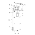
図7も、この発明の他の実施の形態の一例を示す工事用エレベーター装置の上昇移動状態を示す図で、前述の図2相当図である。図において、図5と同符号は相当部分を示し、25は昇降路2の底面に設置されて建築構造体3の直下位置に配置された下部上昇移動滑車である。
【0044】
この図7の実施の形態においても、上部上昇移動滑車24及び下部上昇移動滑車25に巻掛けられて両端がそれぞれつり合おもり5及び移動機械室6の下部に連結されたつり合おもり揚重用ロープ26が設けられる。
【0045】
そして、建物1の上部に設けられたクレーン15によって、つり合おもり5が巻上ロープ18から切離された状態の移動機械室6及びつり合おもり5の少なくとも上方を経由するつり合おもり揚重用ロープ26を介して巻上ロープ18から切離された状態のつり合おもり5が揚重される。したがって、詳細な説明を省略するが図7の実施の形態においても、図5及び図6の実施の形態と同様な作用が得られる。
【0046】
実施の形態4.
図8も、この発明の他の実施の形態の一例を示す工事用エレベーター装置の上昇移動状態を示す図で、前述の図2相当図である。図において、図5と同符号は相当部分を示し、24は上部上昇移動滑車で、二つの滑車が回転軸線を互いに平行に、かつ互いに離れて配置されて構成され、昇降路2最上部の建築構造体3の上側に設けられて建築構造体3の上面に対応して配置されている。25は昇降路2の底面に設置されて昇降路2におけるかご4の区分内に配置された下部上昇移動滑車である。
【0047】
この図8の実施の形態においても、上部上昇移動滑車24及び下部上昇移動滑車25に巻掛けられて両端がそれぞれつり合おもり5及び移動機械室6の下部に連結されたつり合おもり揚重用ロープ26が設けられる。
【0048】
そして、建物1の上部に設けられたクレーン15によって、つり合おもり5が巻上ロープ18から切離された状態の移動機械室6及びつり合おもり5の少なくとも上方を経由するつり合おもり揚重用ロープ26を介して巻上ロープ18から切離された状態のつり合おもり5が揚重される。したがって、詳細な説明を省略するが図8の実施の形態においても、図5及び図6の実施の形態と同様な作用が得られる。
【0049】
【発明の効果】
この発明は以上説明したように、建物に設けられて横断面において建築構造体により区分された昇降路の一側を昇降するかご及び昇降路の他側を昇降するつり合おもりと、巻上機が設置されて昇降路のかごの上方に仮設された移動機械室と、巻上機の駆動綱車に巻掛けられて一端がつり合おもりに切離し自在に接続され他端はかごに配置された巻上ロープと、かごに設けられて巻上ロープのかご側の端部が巻き込まれ繰り出し自在に構成されて巻上ロープを所定長さにおいて固定する巻上ロープ繰出装置と、移動機械室に設けられて要時に巻上ロープを保持する巻上ロープ保持装置と、要時に移動機械室及びつり合いおもりに連結される揚重手段とを備え、移動機械室を延長された昇降路の上端部に移動する際に、かごを昇降路の最下部まで下げ、かごが昇降しないようにするステップと、かごの巻上ロープ繰出装置のロープ保持を解除し、巻上ロープを繰出し可能状態にするステップと、巻上ロープ保持装置により巻上ロープを保持するステップと、つり合おもりに連結された巻上ロープを取外すステップと、建物の上部に設置されたクレーンにより、揚重手段を介して移動機械室及び巻上ロープから切離されたつり合いおもりを引上げ、移動機械室を延長された上方の階床に仮設するステップと、取外された巻上ロープをつり合おもりに連結するステップと、移動機械室の巻上ロープ保持装置の保持力を解除し、かごの巻上ロープ繰出装置により巻上ロープを保持するステップと、移動機械室及びつり合いおもりから揚重手段を撤去するステップと含むものである。
【0050】
これによって、移動機械室の上方移動に際してつり合おもりのみを巻上ロープから外すだけで済み作業を簡略化することができる。また、建物側のクレーンによりつり合おもり及び移動機械室が同時に引上げられるので、建物側のクレーンの使用時間を短縮することができる。また、かごを昇降路の最下部に支持して巻上ロープ繰出装置から巻上ロープを繰出すので、移動機械室の引上げにより所要長さの巻上ロープが自動的に繰出される。したがって、移動機械室の上方移動作業が容易にでき能率を向上する効果がある。
【0051】
また、この発明は以上説明したように、建物に設けられて横断面において建築構造体により区分された昇降路の一側を昇降するかご及び昇降路の他側を昇降するつり合おもりと、巻上機が設置されて昇降路のかごの上方に仮設された移動機械室と、巻上機の駆動綱車に巻掛けられて一端がつり合おもりに切離し自在に接続され他端はかごに配置された巻上ロープと、かごに設けられて巻上ロープのかご側の端部が巻き込まれ繰り出し自在に構成されて巻上ロープを所定長さにおいて固定する巻上ロープ繰出装置と、移動機械室に設けられて要時に巻上ロープを保持する巻上ロープ保持装置と、要時に移動機械室及びつり合いおもりにそれぞれ連結される移動機械室揚重用ロープ及びつり合いおもり揚重用ロープとを備え、移動機械室を延長された昇降路の上端部に移動する際に、かごを昇降路の最下部まで下げ、かごが昇降しないようにするステップと、かごの巻上ロープ繰出装置のロープ保持を解除し、巻上ロープを繰出し可能状態にするステップと、巻上ロープ保持装置により巻上ロープを保持するステップと、つり合おもりに連結された巻上ロープを取外すステップと、建物の上部に設置されたクレーンにより、移動機械室揚重用ロープ及びつり合いおもり揚重用ロープを介して移動機械室及び巻上ロープから切離されたつり合いおもりを引上げ、移動機械室を延長された上方の階床に仮設するステップと、取外された巻上ロープをつり合おもりに連結するステップと、移動機械室の巻上ロープ保持装置の保持力を解除し、かごの巻上ロープ繰出装置により巻上ロープを保持するステップと、移動機械室及びつり合いおもりから移動機械室揚重用ロープ及びつり合いおもり揚重用ロープを撤去するステップと含むものである。
【0052】
これによって、移動機械室の上方移動に際してつり合おもりのみを巻上ロープから外すだけで済み作業を簡略化することができる。また、建物側のクレーンによりつり合おもり及び移動機械室が同時に引上げられるので、建物側のクレーンの使用時間を短縮することができる。また、かごを昇降路の最下部に支持して巻上ロープ繰出装置から巻上ロープを繰出すので、移動機械室の引上げにより所要長さの巻上ロープが自動的に繰出される。
【0053】
また、建物側のクレーンのクレーンロープを上方の開口部から昇降路内に吊下する必要がなく、クレーンロープを建築構造体等の固定物に接触させて損傷する不具合を防ぐことができる。したがって、移動機械室の上方移動作業が容易にでき能率を向上する効果がある。
【0054】
また、この発明は以上説明したように、建物に設けられて横断面において建築構造体により区分された昇降路の一側を昇降するかご及び昇降路の他側を昇降するつり合おもりと、巻上機が設置されて昇降路のかごの上方に仮設された移動機械室と、巻上機の駆動綱車に巻掛けられて一端がつり合おもりに切離し自在に接続され他端はかごに配置された巻上ロープと、かごに設けられて巻上ロープのかご側の端部が巻き込まれ繰り出し自在に構成されて巻上ロープを所定長さにおいて固定する巻上ロープ繰出装置と、移動機械室に設けられて要時に巻上ロープを保持する巻上ロープ保持装置と、要時に両端部がそれぞれつり合いおもり及び移動機械室に連結され、中間部が移動機械室位置よりも下方の昇降路の固定部に枢着された下部上昇移動滑車及び昇降路の最上部に枢着された上部上昇移動滑車に巻掛けられたつり合いおもり揚重用ロープとを備え、移動機械室を延長された昇降路の上端部に移動する際に、かごを昇降路の最下部まで下げ、かごが昇降しないようにするステップと、かごの巻上ロープ繰出装置のロープ保持を解除し、巻上ロープを繰出し可能状態にするステップと、巻上ロープ保持装置により巻上ロープを保持するステップと、つり合おもりに連結された巻上ロープを取外すステップと、建物の上部に設置されたクレーンにより、移動機械室を引上げることにより、この移動機械室に連結されたつり合いおもり揚重用ロープを介して、巻上ロープから切離されたつり合いおもりを引上げ、移動機械室を延長された上方の階床に仮設するステップと、取外された巻上ロープをつり合おもりに連結するステップと、移動機械室の巻上ロープ保持装置の保持力を解除し、かごの巻上ロープ繰出装置により巻上ロープを保持するステップと、移動機械室及びつり合いおもりに連結されたつり合いおもり用揚重ロープを撤去するステップと含むものである。
【0055】
これによって、移動機械室の上方移動に際してつり合おもりのみを巻上ロープから外すだけで済み作業を簡略化することができる。また、建物側のクレーンによりつり合おもり及び移動機械室が同時に引上げられるので、建物側のクレーンの使用時間を短縮することができる。また、かごを昇降路の最下部に支持して巻上ロープ繰出装置から巻上ロープを繰出すので、移動機械室の引上げにより所要長さの巻上ロープが自動的に繰出される。また、移動機械室の上昇移動時にかご揚重用ロープが不要であるので作業を簡易化することができる。したがって、移動機械室の上方移動作業が容易にでき能率を向上する効果がある。
【図面の簡単な説明】
【図1】 この発明の実施の形態1を示す縦断面図。
【図2】 図1の工事用エレベーター装置の上昇移動状態を示す図。
【図3】 図1の工事用エレベーター装置の上昇移動後の状態を示す図。
【図4】 図1の工事用エレベーター装置の上昇移動の手順を説明する工程図。
【図5】 この発明の実施の形態2を示す工事用エレベーター装置の上昇移動状態を示す図で、前述の図1相当図。
【図6】 図5の工事用エレベーター装置の上昇移動の手順を説明する工程図。
【図7】 この発明の実施の形態3を示す工事用エレベーター装置の上昇移動状態を示す図で、前述の図1相当図。
【図8】 この発明の実施の形態4を示す工事用エレベーター装置の上昇移動状態を示す図で、前述の図1相当図。
【図9】 従来の工事用エレベーター装置を示す縦断面図。
【図10】 図9の工事用エレベーター装置の上昇移動状態を示す図。
【図11】 図9の工事用エレベーター装置の上昇移動後における状態を示す図。
【符号の説明】
1 建物、2 昇降路、3 建築構造体、4 かご、5 つり合おもり、6 移動機械室、8 駆動綱車、9 巻上機、15 クレーン、18 巻上ロープ、19 巻上ロープ繰出装置、21 かご揚重用ロープ、22 つり合おもり揚重用ロープ、26 つり合おもり揚重用ロープ。[0001]
BACKGROUND OF THE INVENTION
This invention is a method of ascending and moving a construction elevator in which the ascending / descending process is extended upward as the building work progresses from the lower floor to the upper floor.To the lawRelated.
[0002]
[Prior art]
9 to 11 are views showing a construction elevator apparatus similar to the conventional construction elevator apparatus disclosed in, for example, Japanese Patent Application Laid-Open No. 57-38283. FIG. 9 is a longitudinal sectional view, and FIG. FIG. 11 is a diagram showing a state after the upward movement of the construction elevator apparatus of FIG. 9. In the figure, 1 is a building, 2 is a hoistway provided in the
[0003]
4 is a cage for raising and lowering one side of the
[0004]
A
[0005]
The conventional construction elevator apparatus is configured as described above, and the
[0006]
Thereby, the operation | work for the construction of the elevator in the raising / lowering process by the
[0007]
That is, the
[0008]
Next, the
[0009]
[Problems to be solved by the invention]
In the conventional construction elevator apparatus as described above, the elevating path of the
[0010]
The present invention has been made to solve such problems, and to obtain a construction elevator ascending and moving method and a construction elevator device capable of moving up a moving machine room with simple work and at low cost. With the goal.
[0011]
[Means for Solving the Problems]
In the ascending and moving method of the construction elevator according to the present invention, the cage is provided in the building and lifts and lowers one side of the hoistway divided by the building structure in the cross section, and the counterweight lifts and lowers the other side of the hoistway. And a moving machine room temporarily installed above the car of the hoistway where the hoisting machine is installed, and one end of the hoisting machine is wound around the driving sheave and connected to the counterweight so that the other end is freely connected. A hoisting rope disposed in the car, and a hoisting rope feeding device that is provided on the car and is configured so that the end portion on the car side of the hoisting rope is wound up and can be fed out to fix the hoisting rope at a predetermined length.A hoisting rope holding device which is provided in the moving machine room and holds the hoisting rope when necessary, and a lifting means connected to the moving machine room and the counterweight when necessary, When moving the moving machine room to the upper end of the extended hoistway, lower the car to the lowermost part of the hoistway so that the car does not move up and down, and release the rope holding of the car hoisting rope feeding device Installed in the upper part of the building, the step of making the hoisting rope ready to be fed, the step of holding the hoisting rope by the hoisting rope holding device, the step of removing the hoisting rope connected to the counterweight Lifting the counterweight separated from the moving machine room and the hoisting rope by the lifting means, temporarily setting the moving machine room on the extended upper floor, and removing the hoisting A step of connecting the rope to the counterweight, a step of releasing the holding force of the hoisting rope holding device of the moving machine room and holding the hoisting rope by the hoisting rope feeding device of the car, and the moving machine room It is intended to include a step of removing the lifting means from Bitsuriai weight.
[0012]
Also, JianOf the hoistway that is provided on the object and is lifted up and down on one side of the hoistway divided by the building structure in the cross-section and the hoisting machine A moving machine room that is temporarily installed above, a hoisting rope that is wound around a driving sheave of the hoisting machine and has one end detachably connected to the counterweight and the other end arranged on the car, and a car A hoisting rope feeding device configured so that the end of the hoisting rope on the side of the car is caught and freely drawn out, and fixes the hoisting rope at a predetermined length;A hoisting rope holding device which is provided in the moving machine room and holds the hoisting rope when necessary, and a moving machine room lifting rope and a counterweight hoisting rope respectively connected to the moving machine room and the counterweight when necessary. When moving the mobile machine room to the upper end of the extended hoistway, lowering the car to the lowermost part of the hoistway so that the car does not move up and down, and holding the rope of the car hoisting rope feeding device To release the hoisting rope, to allow the hoisting rope to be unwound, to hold the hoisting rope by the hoisting rope holding device, to remove the hoisting rope connected to the counterweight, and to the upper part of the building. The installed crane lifts the counterweight separated from the mobile machine room and the hoisting rope via the lifting rope and the counterweight lifting rope. Temporarily releasing the moving machine room on the extended upper floor, connecting the removed hoisting rope to the counterweight, and releasing the holding force of the hoisting rope holding device of the moving machine room; A step of holding the hoisting rope by the hoisting rope feeding device of the car, and a step of removing the moving machine room lifting rope and the counterweight lifting rope from the moving machine room and the counterweight..
[0013]
Also, JianOf the hoistway that is provided on the object and is lifted up and down on one side of the hoistway divided by the building structure in the cross-section and the hoisting machine A moving machine room that is temporarily installed above, a hoisting rope that is wound around a driving sheave of the hoisting machine and has one end detachably connected to the counterweight and the other end arranged on the car, and a car A hoisting rope feeding device configured so that the end of the hoisting rope on the side of the car is caught and freely drawn out, and fixes the hoisting rope at a predetermined length;A hoisting rope holding device that is provided in the moving machine room and holds the hoisting rope when necessary, and both ends are respectively connected to the counterweight and the moving machine room when necessary, and the intermediate part is below the position of the moving machine room. The lower lift moving pulley pivotally attached to the fixed part of the hoistway and the counterweight lifting rope wound around the upper lift moving pulley pivotally attached to the uppermost part of the hoistway, and the mobile machine room is extended. When moving to the upper end of the hoistway, lower the car to the lowest part of the hoistway so that the car does not go up and down, release the rope holding of the car hoisting rope feeding device, and feed the hoisting rope The step of making it possible, the step of holding the hoisting rope with the hoisting rope holding device, the step of removing the hoisting rope connected to the counterweight, and the crane installed at the top of the building. By lifting the machine room, the counterweight separated from the hoisting rope is pulled up via the counterweight lifting rope connected to the mobile machine room, and the mobile machine room is extended to the extended upper floor. The step of temporarily setting, the step of connecting the removed hoisting rope to the counterweight, the holding force of the hoisting rope holding device of the moving machine room is released, and the hoisting rope is moved by the hoisting rope feeding device of the car. And holding and removing the counterweight lifting rope connected to the mobile machine room and the counterweight..
[0014]
DETAILED DESCRIPTION OF THE INVENTION
1-4 is a figure which shows an example of embodiment of this invention, FIG. 1 is a longitudinal cross-sectional view, FIG. 2 is a figure which shows the raising movement state of the construction elevator apparatus of FIG. 1, FIG. 3 is FIG. FIG. 4 is a process diagram for explaining the procedure of the upward movement of the construction elevator apparatus of FIG. 1. In the figure, 1 is a building, 2 is a hoistway provided in the
[0015]
4 is a cage for raising and lowering one side of the
[0016]
13 is a car collision receiver provided at the bottom of the
[0017]
20 is a lifting device provided at the lower end of the
[0018]
In the construction elevator apparatus configured as described above, the moving
[0019]
Thereby, the operation | work for the construction of the elevator in the raising / lowering process by the
[0020]
That is, in step 101, the
[0021]
Next, it progresses to step 104, the hoisting
[0022]
Then, the moving
[0023]
Next, the routine proceeds to step 109, where the
[0024]
In short, for the lifting of the counterweight via at least the upper part of the moving
[0025]
By such an apparatus configuration or a method of ascending and moving the construction elevator by the apparatus configuration, only the
[0026]
Therefore, the
Moreover, since the
[0027]
Further, the
[0028]
Further, since the
[0029]
5 and 6 are diagrams showing an example of another embodiment of the present invention, and FIG. 5 is a diagram showing an upward movement state of the construction elevator device.2FIG. 6 is a process diagram for explaining the procedure of the upward movement of the construction elevator apparatus of FIG. In the figure, the same reference numerals as in FIGS.
[0030]
[0031]
In the construction elevator apparatus configured as described above, the moving
[0032]
Thereby, the operation | work for the construction of the elevator in the raising / lowering process by the
[0033]
That is, in
[0034]
Next, the routine proceeds to step 204, where the hoisting
[0035]
Next, the process proceeds to step 207 where the
[0036]
Next, the routine proceeds to step 208, where the hoisting
[0037]
Next, the routine proceeds to step 210, where the
[0038]
In short, for the lifting of the counterweight via at least the upper part of the moving
[0039]
Therefore, although the detailed description is omitted, the apparatus configuration in the embodiment of FIG. 5 and FIG. 6 or the method of ascending and moving the construction elevator by the apparatus configuration has the same effect as the embodiment of FIG. Obtainable.
[0040]
5 and 6, the upper ascending
[0041]
Also, the counterweight lifting rope 26Thus, the
Further, since the
[0042]
Also, the
[0043]
FIG. 7 is also a diagram showing an ascending movement state of a construction elevator apparatus showing an example of another embodiment of the present invention,2It is an equivalent figure. In the figure, the same reference numerals as those in FIG. 5 denote corresponding parts, and 25 is a lower ascending movable pulley installed on the bottom surface of the
[0044]
Also in the embodiment of FIG. 7, the counterweight lifting rope wound around the upper ascending
[0045]
Then, for the lifting of the counterweight through at least the upper part of the moving
[0046]
FIG. 8 is also a diagram showing the upward movement state of the construction elevator device showing an example of another embodiment of the present invention,2It is an equivalent figure. In the figure, the same reference numerals as those in FIG. 5 denote the corresponding parts, and
[0047]
Also in the embodiment of FIG. 8, the counterweight lifting rope wound around the upper
[0048]
Then, for the lifting and lifting of the counterweight via at least the upper part of the moving
[0049]
【The invention's effect】
As described above, the present invention provides a car that lifts and lowers one side of a hoistway that is provided in a building and divided by a building structure in a cross section, and a counterweight that lifts and lowers the other side of the hoistway, and a hoisting machine Is installed on the hoistway cage, and the hoisting machine drive sheave is wound around one end of the hoistway so that it can be separated from the counterweight and the other end is placed on the car. A hoisting rope, and a hoisting rope feeding device that is provided on the car and is configured to be freely drawn out by being wound at an end of the hoisting rope on the car side, and fixing the hoisting rope at a predetermined length;A hoisting rope holding device provided in the moving machine room for holding the hoisting rope when necessary, and lifting means connected to the moving machine room and the counterweight when necessary, and extending the moving machine room When moving to the upper end of the road, the step of lowering the car to the lowest part of the hoistway to prevent the car from going up and down, releasing the rope holding of the car hoisting rope feeding device and feeding the hoisting rope The lifting means is provided by a step of setting the state, a step of holding the hoisting rope by the hoisting rope holding device, a step of removing the hoisting rope connected to the counterweight, and a crane installed at the top of the building. The lifting weight separated from the moving machine room and the hoisting rope is pulled up, and the step of temporarily setting the moving machine room on the extended upper floor and the removed hoisting rope are connected to the counterweight. Removing the holding force of the hoisting rope holding device of the moving machine room, holding the hoisting rope by the hoisting rope feeding device of the car, and removing the lifting means from the moving machine room and the counterweight Including stepsIs.
[0050]
Accordingly, it is only necessary to remove the counterweight from the hoisting rope when the mobile machine room is moved upward, and the work can be simplified. Moreover, since the counterweight and the moving machine room are pulled up simultaneously by the crane on the building side, the usage time of the crane on the building side can be shortened. Further, since the car is supported at the lowermost part of the hoistway and the hoisting rope is fed out from the hoisting rope feeding device, the hoisting rope of a required length is automatically fed out by pulling up the moving machine room. Therefore, it is possible to easily move the moving machine room upward and to improve the efficiency.
[0051]
In addition, as described above, the present inventionJianOf the hoistway which is provided on the object and which is lifted up and down the other side of the hoistway, and a hoisting machine installed in the hoistway car A moving machine room temporarily installed above, a hoisting rope that is wound around a driving sheave of a hoisting machine, one end of which is detachably connected to a counterweight and the other end is arranged in a car, and a car A hoisting rope feeding device configured so that the end of the hoisting rope on the side of the car is caught and freely drawn out, and fixes the hoisting rope at a predetermined length;A hoisting rope holding device which is provided in the moving machine room and holds the hoisting rope when necessary, and a moving machine room lifting rope and a counterweight hoisting rope respectively connected to the moving machine room and the counterweight when necessary. When moving the mobile machine room to the upper end of the extended hoistway, lowering the car to the lowermost part of the hoistway so that the car does not move up and down, and holding the rope of the car hoisting rope feeding device To release the hoisting rope, to allow the hoisting rope to be unwound, to hold the hoisting rope by the hoisting rope holding device, to remove the hoisting rope connected to the counterweight, and to the upper part of the building. The installed crane lifts the counterweight separated from the mobile machine room and the hoisting rope via the lifting rope and the counterweight lifting rope. Temporarily releasing the moving machine room on the extended upper floor, connecting the removed hoisting rope to the counterweight, and releasing the holding force of the hoisting rope holding device of the moving machine room; A step of holding the hoisting rope by the hoisting rope feeding device of the car, and a step of removing the moving machine room lifting rope and the counterweight lifting rope from the moving machine room and the counterweight..
[0052]
Accordingly, it is only necessary to remove the counterweight from the hoisting rope when the mobile machine room is moved upward, and the work can be simplified. Moreover, since the counterweight and the moving machine room are pulled up simultaneously by the crane on the building side, the usage time of the crane on the building side can be shortened. Further, since the car is supported at the lowermost part of the hoistway and the hoisting rope is fed out from the hoisting rope feeding device, the hoisting rope of a required length is automatically fed out by pulling up the moving machine room.
[0053]
Moreover, it is not necessary to suspend the crane rope of the crane on the building side from the upper opening in the hoistway, and it is possible to prevent the crane rope from being damaged by being brought into contact with a fixed object such as a building structure. Therefore, it is possible to easily move the moving machine room upward and to improve the efficiency.
[0054]
In addition, as described above, the present inventionJianOf the hoistway that is provided on the object and is lifted up and down on one side of the hoistway divided by the building structure in the cross-section and the hoisting machine A moving machine room that is temporarily installed above, a hoisting rope that is wound around a driving sheave of the hoisting machine and has one end detachably connected to the counterweight and the other end arranged on the car, and a car A hoisting rope feeding device configured so that the end of the hoisting rope on the side of the car is caught and freely drawn out, and fixes the hoisting rope at a predetermined length;A hoisting rope holding device that is provided in the moving machine room and holds the hoisting rope when necessary, and both ends are respectively connected to the counterweight and the moving machine room when necessary, and the intermediate part is below the position of the moving machine room. The lower lift moving pulley pivotally attached to the fixed part of the hoistway and the counterweight lifting rope wound around the upper lift moving pulley pivotally attached to the uppermost part of the hoistway, and the mobile machine room is extended. When moving to the upper end of the hoistway, lower the car to the lowest part of the hoistway so that the car does not go up and down, release the rope holding of the car hoisting rope feeding device, and feed the hoisting rope The step of making it possible, the step of holding the hoisting rope with the hoisting rope holding device, the step of removing the hoisting rope connected to the counterweight, and the crane installed at the top of the building. By lifting the machine room, the counterweight separated from the hoisting rope is pulled up via the counterweight lifting rope connected to the mobile machine room, and the mobile machine room is extended to the extended upper floor. The step of temporarily setting, the step of connecting the removed hoisting rope to the counterweight, the holding force of the hoisting rope holding device of the moving machine room is released, and the hoisting rope is moved by the hoisting rope feeding device of the car. And holding and removing the counterweight lifting rope connected to the mobile machine room and the counterweight..
[0055]
Accordingly, it is only necessary to remove the counterweight from the hoisting rope when the mobile machine room is moved upward, and the work can be simplified. Moreover, since the counterweight and the moving machine room are pulled up simultaneously by the crane on the building side, the usage time of the crane on the building side can be shortened. Further, since the car is supported at the lowermost part of the hoistway and the hoisting rope is fed out from the hoisting rope feeding device, the hoisting rope of a required length is automatically fed out by pulling up the moving machine room. Further, since the car lifting rope is not required when the mobile machine room is moved up, the operation can be simplified. Therefore, it is possible to easily move the moving machine room upward and to improve the efficiency.
[Brief description of the drawings]
FIG. 1 is a longitudinal sectional
FIG. 2 is a diagram showing an upward movement state of the construction elevator apparatus of FIG. 1;
FIG. 3 is a diagram showing a state after the ascending movement of the construction elevator apparatus of FIG. 1;
FIG. 4 is a process diagram for explaining a procedure for ascending movement of the construction elevator apparatus of FIG. 1;
FIG. 5 is a diagram showing the upward movement state of the construction elevator apparatus according to
6 is a process diagram illustrating the procedure of ascending movement of the construction elevator apparatus of FIG. 5;
FIG. 7 is a diagram showing a rising movement state of a construction elevator apparatus according to
FIG. 8 is a diagram showing an ascending movement state of a construction elevator
FIG. 9 is a longitudinal sectional view showing a conventional construction elevator apparatus.
FIG. 10 is a diagram showing an upward movement state of the construction elevator apparatus of FIG. 9;
FIG. 11 is a diagram showing a state after the ascending movement of the construction elevator apparatus of FIG. 9;
[Explanation of symbols]
1 building, 2 hoistway, 3 building structure, 4 car, 5 counterweight, 6 moving machine room, 8 drive sheave, 9 hoisting machine, 15 crane, 18 hoisting rope, 19 hoisting rope feeding device, 21 basket lifting rope, 22 counterweight lifting rope, 26 counterweight lifting rope.
Claims (3)
移動機械室を延長された昇降路の上端部に移動する際に、かごを昇降路の最下部まで下げ、かごが昇降しないようにするステップと、かごの巻上ロープ繰出装置のロープ保持を解除し、巻上ロープを繰出し可能状態にするステップと、巻上ロープ保持装置により巻上ロープを保持するステップと、つり合おもりに連結された巻上ロープを取外すステップと、建物の上部に設置されたクレーンにより、揚重手段を介して移動機械室及び巻上ロープから切離されたつり合いおもりを引上げ、移動機械室を延長された上方の階床に仮設するステップと、取外された巻上ロープをつり合おもりに連結するステップと、移動機械室の巻上ロープ保持装置の保持力を解除し、かごの巻上ロープ繰出装置により巻上ロープを保持するステップと、移動機械室及びつり合いおもりから揚重手段を撤去するステップと含むことを特徴とする工事用エレベーターの上昇移動方法。There is a car that lifts and lowers one side of a hoistway that is provided in a building and divided by a building structure in a cross section, a counterweight that elevates and lowers the other side of the hoistway, and a hoisting machine is installed to A moving machine room temporarily installed above the car, and a hoisting rope wound around a driving sheave of the hoisting machine and having one end detachably connected to the counterweight and the other end arranged on the car A hoisting rope feeding device that is provided on the car and is configured so that the end of the hoisting rope on the car side is wound up and freely fed out, and fixes the hoisting rope at a predetermined length, and the moving machine chamber A hoisting rope holding device that holds the hoisting rope when needed, and a lifting means connected to the moving machine room and the counterweight when needed,
When moving the moving machine room to the upper end of the extended hoistway, lower the car to the lowermost part of the hoistway so that the car does not move up and down, and release the rope holding of the car hoisting rope feeding device Installed in the upper part of the building, the step of making the hoisting rope ready to be fed, the step of holding the hoisting rope by the hoisting rope holding device, the step of removing the hoisting rope connected to the counterweight Lifting the counterweight separated from the moving machine room and the hoisting rope by the lifting means, temporarily setting the moving machine room on the extended upper floor, and removing the hoisting A step of connecting the rope to the counterweight, a step of releasing the holding force of the hoisting rope holding device of the moving machine room and holding the hoisting rope by the hoisting rope feeding device of the car, and the moving machine room Upward movement process of construction elevators, which comprises from Bitsuriai weight and the step of removing the lifting means.
移動機械室を延長された昇降路の上端部に移動する際に、かごを昇降路の最下部まで下げ、かごが昇降しないようにするステップと、かごの巻上ロープ繰出装置のロープ保持を解除し、巻上ロープを繰出し可能状態にするステップと、巻上ロープ保持装置により巻上ロープを保持するステップと、つり合おもりに連結された巻上ロープを取外すステップと、建物の上部に設置されたクレーンにより、移動機械室揚重用ロープ及びつり合いおもり揚重用ロープを介して移動機械室及び巻上ロープから切離されたつり合いおもりを引上げ、移動機械室を延長された上方の階床に仮設するステップと、取外された巻上ロープをつり合おもりに連結するステップと、移動機械室の巻上ロープ保持装置の保持力を解除し、かごの巻上ロープ繰出装置により巻上ロープを保持するステップと、移動機械室及びつり合いおもりから移動機械室揚重用ロープ及びつり合いおもり揚重用ロープを撤去するステップと含むことを特徴とする工事用エレベーターの上昇移動方法。 There is a car that lifts and lowers one side of a hoistway that is provided in a building and divided by a building structure in a cross section, a counterweight that elevates and lowers the other side of the hoistway, and a hoisting machine is installed to A moving machine room temporarily installed above the car, and a hoisting rope wound around a driving sheave of the hoisting machine and having one end detachably connected to the counterweight and the other end arranged on the car A hoisting rope feeding device that is provided on the car and is configured so that the end of the hoisting rope on the car side is wound up and freely fed out, and fixes the hoisting rope at a predetermined length, and the moving machine chamber A hoisting rope holding device that holds the hoisting rope when necessary, and a moving machine room lifting rope and a counterweight lifting rope that are respectively connected to the moving machine room and the counterweight when necessary,
When moving the moving machine room to the upper end of the extended hoistway, lower the car to the lowermost part of the hoistway so that the car does not move up and down, and release the rope holding of the car hoisting rope feeding device Installed in the upper part of the building, the step of making the hoisting rope ready to be fed, the step of holding the hoisting rope by the hoisting rope holding device, the step of removing the hoisting rope connected to the counterweight The lifting weight separated from the moving machine room and the hoisting rope is pulled up by the moving crane through the moving machine room lifting rope and the lifting weight lifting rope, and the moving machine room is temporarily set on the extended upper floor. A step, a step of connecting the removed hoisting rope to the counterweight, a holding force of the hoisting rope holding device of the moving machine room is released, and the hoisting rope feeding device of the car Step a mobile machine room and the balancing upward movement process of construction elevators, which comprises a step of removing the mobile machine room lifting duty ropes and counterweight lifting duty rope from the weight to hold the hoisting ropes.
移動機械室を延長された昇降路の上端部に移動する際に、かごを昇降路の最下部まで下げ、かごが昇降しないようにするステップと、かごの巻上ロープ繰出装置のロープ保持を解除し、巻上ロープを繰出し可能状態にするステップと、巻上ロープ保持装置により巻上ロープを保持するステップと、つり合おもりに連結された巻上ロープを取外すステップと、建物の上部に設置されたクレーンにより、移動機械室を引上げることにより、この移動機械室に連結されたつり合いおもり揚重用ロープを介して、巻上ロープから切離されたつり合いおもりを引上げ、移動機械室を延長された上方の階床に仮設するステップと、取外された巻上ロープをつり合おもりに連結するステップと、移動機械室の巻上ロープ保持装置の保持力を解除し、かごの巻上ロープ繰出装置により巻上ロープを保持するステップと、移動機械室及びつり合いおもりに連結されたつり合いおもり用揚重ロープを撤去するステップと含むことを特徴とする工事用エレベーターの上昇移動方法。 There is a car that lifts and lowers one side of a hoistway that is provided in a building and divided by a building structure in a cross section, a counterweight that elevates and lowers the other side of the hoistway, and a hoisting machine is installed to A moving machine room temporarily installed above the car, and a hoisting rope wound around a driving sheave of the hoisting machine and having one end detachably connected to the counterweight and the other end arranged on the car A hoisting rope feeding device that is provided on the car and is configured so that the end of the hoisting rope on the car side is wound up and freely fed out, and fixes the hoisting rope at a predetermined length, and the moving machine chamber A hoisting rope holding device that holds the hoisting rope when necessary, and both ends of the hoisting rope are connected to the counterweight and the moving machine room, and the intermediate part is lower than the moving machine chamber position when necessary. Pivot to the fixed part of the road Has been a counterweight fried duty ropes wound around the upper upward movement pulley that is pivotally attached to the top of the bottom upward movement pulley and the hoistway,
When moving the moving machine room to the upper end of the extended hoistway, lower the car to the lowermost part of the hoistway so that the car does not move up and down, and release the rope holding of the car hoisting rope feeding device Installed in the upper part of the building, the step of making the hoisting rope ready to be fed, the step of holding the hoisting rope by the hoisting rope holding device, the step of removing the hoisting rope connected to the counterweight By lifting the mobile machine room using a crane, the counterweight lifted off the hoisting rope was lifted through the counterweight lifting rope connected to the mobile machine room, and the mobile machine room was extended. Release the holding force of the hoisting rope holding device of the moving machine room, the step of temporarily installing on the upper floor, the step of connecting the removed hoisting rope to the counterweight, and winding the car Step a mobile machine room and the balancing upward movement process of construction elevators, which comprises a step of removing the weight for lifting ropes balance coupled to the weight to hold the hoisting ropes by rope feeding device.
Priority Applications (1)
| Application Number | Priority Date | Filing Date | Title |
|---|---|---|---|
| JP9714896A JP3807775B2 (en) | 1996-04-18 | 1996-04-18 | How to lift the construction elevator |
Applications Claiming Priority (1)
| Application Number | Priority Date | Filing Date | Title |
|---|---|---|---|
| JP9714896A JP3807775B2 (en) | 1996-04-18 | 1996-04-18 | How to lift the construction elevator |
Publications (2)
| Publication Number | Publication Date |
|---|---|
| JPH09278325A JPH09278325A (en) | 1997-10-28 |
| JP3807775B2 true JP3807775B2 (en) | 2006-08-09 |
Family
ID=14184496
Family Applications (1)
| Application Number | Title | Priority Date | Filing Date |
|---|---|---|---|
| JP9714896A Expired - Fee Related JP3807775B2 (en) | 1996-04-18 | 1996-04-18 | How to lift the construction elevator |
Country Status (1)
| Country | Link |
|---|---|
| JP (1) | JP3807775B2 (en) |
Families Citing this family (7)
| Publication number | Priority date | Publication date | Assignee | Title |
|---|---|---|---|---|
| FI20000499A0 (en) * | 2000-03-03 | 2000-03-03 | Kone Corp | Elevator arrangement for use during construction and procedure for raising the level of the engine room |
| EP1245522B1 (en) * | 2001-01-22 | 2004-07-28 | Inventio Ag | Procedure for mounting a drive unit in an elevator shaft |
| JP4443171B2 (en) * | 2003-09-04 | 2010-03-31 | 三菱電機株式会社 | Elevator rope feeding device for construction |
| FI20090389A (en) * | 2009-10-23 | 2011-04-24 | Kone Corp | A method of making a lift |
| JP6174436B2 (en) * | 2013-09-27 | 2017-08-02 | 前田建設工業株式会社 | High-rise building demolished material transfer method and transfer equipment |
| CN104499719B (en) * | 2014-12-23 | 2016-10-26 | 泰州市腾达建筑工程机械有限公司 | A kind of building material lifting device by water-cooling |
| CN110844743B (en) * | 2018-08-21 | 2022-07-12 | 奥的斯电梯公司 | Skip-floor elevator and skip-floor method |
-
1996
- 1996-04-18 JP JP9714896A patent/JP3807775B2/en not_active Expired - Fee Related
Also Published As
| Publication number | Publication date |
|---|---|
| JPH09278325A (en) | 1997-10-28 |
Similar Documents
| Publication | Publication Date | Title |
|---|---|---|
| EP2349902B1 (en) | Method of installing an elevator | |
| WO2017051066A1 (en) | Method for installing an elevator in the construction phase of a building | |
| CN112566864B (en) | Application method of lift extension technology of elevator | |
| JP3807775B2 (en) | How to lift the construction elevator | |
| JP6969686B2 (en) | How to extend the lift of a construction elevator | |
| JP2001114484A (en) | Construction method for suspending elevator main rope | |
| JPH0624673A (en) | Elevator structure having climbing device in lift of cage for construction work | |
| JP2510732B2 (en) | Main loop replacement auxiliary device | |
| JP2004238151A (en) | Installation method for elevator | |
| JP3841616B2 (en) | Elevator main rope replacement method and apparatus | |
| JP2011102177A (en) | Confinement rescue method for elevator | |
| JP2003128359A (en) | Roping method for elevator | |
| JPH11199157A (en) | Existing main rope take-up device for elevator | |
| JP2839970B2 (en) | Elevator main cable replacement method | |
| JPH082850A (en) | Work method in elevator shaft | |
| JP3353032B2 (en) | elevator | |
| JP5058181B2 (en) | How to hang an elevator rope | |
| JP2603730B2 (en) | How to change the elevator main rope | |
| CN114728762B (en) | Rope conveying support auxiliary device for elevator rope replacing operation | |
| JP3020325B2 (en) | Elevator main cable replacement method | |
| JP3920527B2 (en) | Elevator for construction | |
| JPH0818774B2 (en) | How to change the elevator main rope | |
| JP4037604B2 (en) | Elevator rope replacement method | |
| JP2654409B2 (en) | Elevator main cable replacement method | |
| JPH08133634A (en) | Jumping method for jump-up elevator |
Legal Events
| Date | Code | Title | Description |
|---|---|---|---|
| A131 | Notification of reasons for refusal |
Free format text: JAPANESE INTERMEDIATE CODE: A131 Effective date: 20060124 |
|
| A521 | Written amendment |
Free format text: JAPANESE INTERMEDIATE CODE: A523 Effective date: 20060227 |
|
| TRDD | Decision of grant or rejection written | ||
| A01 | Written decision to grant a patent or to grant a registration (utility model) |
Free format text: JAPANESE INTERMEDIATE CODE: A01 Effective date: 20060509 |
|
| A61 | First payment of annual fees (during grant procedure) |
Free format text: JAPANESE INTERMEDIATE CODE: A61 Effective date: 20060516 |
|
| R150 | Certificate of patent (=grant) or registration of utility model |
Free format text: JAPANESE INTERMEDIATE CODE: R150 |
|
| LAPS | Cancellation because of no payment of annual fees |