JP3793425B2 - Construction machine display device - Google Patents
Construction machine display device Download PDFInfo
- Publication number
- JP3793425B2 JP3793425B2 JP2001149937A JP2001149937A JP3793425B2 JP 3793425 B2 JP3793425 B2 JP 3793425B2 JP 2001149937 A JP2001149937 A JP 2001149937A JP 2001149937 A JP2001149937 A JP 2001149937A JP 3793425 B2 JP3793425 B2 JP 3793425B2
- Authority
- JP
- Japan
- Prior art keywords
- display
- liquid crystal
- displayed
- needle
- display area
- Prior art date
- Legal status (The legal status is an assumption and is not a legal conclusion. Google has not performed a legal analysis and makes no representation as to the accuracy of the status listed.)
- Expired - Fee Related
Links
- 238000010276 construction Methods 0.000 title claims description 22
- 239000004973 liquid crystal related substance Substances 0.000 claims description 39
- 230000005856 abnormality Effects 0.000 claims description 9
- 238000012544 monitoring process Methods 0.000 claims description 6
- 230000002159 abnormal effect Effects 0.000 description 10
- 239000000446 fuel Substances 0.000 description 10
- XLYOFNOQVPJJNP-UHFFFAOYSA-N water Substances O XLYOFNOQVPJJNP-UHFFFAOYSA-N 0.000 description 6
- 239000000498 cooling water Substances 0.000 description 5
- 239000010720 hydraulic oil Substances 0.000 description 4
- 238000005259 measurement Methods 0.000 description 4
- 239000003921 oil Substances 0.000 description 2
- 239000002826 coolant Substances 0.000 description 1
- 230000000694 effects Effects 0.000 description 1
Images


Landscapes
- Component Parts Of Construction Machinery (AREA)
- Indicating Measured Values (AREA)
- Instrument Panels (AREA)
- Devices For Indicating Variable Information By Combining Individual Elements (AREA)
Description
【0001】
【発明の属する技術分野】
この発明は、建設機械における各種の監視または警報の表示対象を表示する表示装置の改良に関する。
【0002】
【従来の技術】
一般に、建設機械、特に油圧ショベルの表示装置にあっては、燃料、エンジン冷却水を監視する他にショベルを駆動する作動油の温度も監視する必要があり、またバッテリーやオイル圧力等についての警報も入れると、表示対象の数が相当数に上り、限られたスペースの中で、それら全ての対象を配置しなければならない。
そこで、従来の表示装置としては、図7に示すように、従来の建設機械の表示装置31では、例えば燃料計32、エンジンの冷却水の水温計33、作動油の油温計34の三個の針式ゲージと、複数個の警報を表示する警報灯群35とが組み合わされた構成が知られている。
上記の針式ゲージ32〜34において、表示印刷面37に印刷された目盛り表示部32a、33a、34aは、表示対象ごとに描かれており固定位置に配置されている。なお、符号32b、33b、34bは、ゲージ用の針を示している。
【0003】
この表示装置では、図8に示すように、針式ゲージ32の針32bを駆動するムーブメント38は、表示印刷面37の裏側に配置され、このムーブメント38から延びるシャフト38aが表示印刷面37を貫通して針32bの基端に連結されている。
【0004】
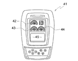
次に、図9に示す従来の建設機械の表示装置41では、液晶表示により表示対象の変化量を示す燃料計42、エンジンの冷却水の水温計43、作動油の油温計44と、警報を文字表示する液晶表示画面45とが組み合わされた構成からなっている。
しかしながら、上記図7及び8に示すアナログ式の表示装置31にあっては、針式ゲージ32〜34の目盛り表示部32a〜34aが表示印刷面37に印刷され固定されているので、それぞれの針式ゲージ32〜34の大きさが制限され、またそれぞれの針式ゲージ32〜34が提供する計測情報も一つに固定されている。
また、図9に示す表示装置41にあっては、液晶式ゲージ42〜44であり、針式ゲージに比べて視認性に制限がある。
【0005】
【発明が解決しようとする課題】
この発明は上述した事情に鑑みてなされたものであり、その主たる課題は、視認性に優れている共に、状況により各種の表示対象からオペレータが必要とする表示対象を選択して表示することができる建設機械の表示装置を提供することにある。
【0006】
【課題を解決するための手段】
上記課題を達成するために、請求項1の発明では、
建設機械における各種の監視または警報の表示対象を表示する表示装置において、
複数の表示対象から選択された1つの表示対象を画面上の主たる表示領域に表示しうる液晶表示面と、
該液晶表示面の視認方向手前に配置されて、主たる表示領域に表示された目盛りを指示する針式ゲージとを備え、
該針式ゲージを駆動するムーブメントが、針式ゲージより視認方向手前に設けられた表示装置のケーシングの内壁に取り付けられている、という技術的手段を講じている。
また、請求項2の発明では、
上記液晶表示面には、一つの主たる表示領域と、一または複数の副たる表示領域が同時に表示されるようになっており、副たる表示領域に表示された表示対象と主たる表示領域に表示された表示対象とが交替するよう切り替え可能となっており、
画面の全部または一部が文字または図形を表示する表示領域になると、針式ゲージの針は上記表示領域を交差しない待機位置に変位してなるこ、という技術的手段を講じている。
請求項3の発明では、
建設機械に所定の異常が発生すると、上記針式ゲージの針が待機位置に戻り、主たる表示領域に文字または図形が表示されて異常警報を表示しうる、という技術的手段を講じている。
また、請求項4の発明では、
上記液晶表示面と上記針式ゲージの間に、光源を有する発光板を配置し、
該発光板には、目盛り対応位置に開口部を穿設してなり、
該開口部から上記液晶表示面に表示された目盛りの液晶表示が見えるように形成されている、という技術的手段を講じている。
【0007】
【発明の実施の形態】
以下に、この発明の建設機械の表示装置の実施例について図を参照しながら説明する。
表示装置1は、運転席の適宜個所、例えばコンソールボックスの上面や運転室の正面のパネル(図示省略)等に設置されるものであり、図1および図2に示すように、建設機械の各コンポーネントを監視するセンサ群Sが計測した値をもとにコントローラCが制御して表示するようになっている。
【0008】
この表示装置1は、表面に透明板5aを設けたケーシング5内に、複数の表示対象から選択された1つの表示対象を画面上の主たる表示領域E1に表示する液晶表示面2と、該液晶表示面2の上方に配置されて、主たる表示領域E1に表示された目盛り表示部4の指針となる針3とを備えた構成からなっている。
【0009】
図示例の場合、液晶表示面2の中央主要部の大きなスペースが主たる表示領域E1となっており、該主たる表示領域E1には、表示対象の1つとしてオペレータの確認頻度の高い燃料計の目盛り表示部4が表示されている。
この燃料計の目盛り表示部4は、表示対象の種別を示す燃料計のシンボルアイコン22が略中央に表示され、その外側に円弧状に形成された燃料計用の目盛り12と、その目盛り12の外側で度合いを示す文字(図示例では、0を示すEと、1/2と、満タンを示すF)13とからなっている。
【0010】
次に、この目盛り表示部4の目盛り12と交差して指針となるゲージ用針3がケーシング5の上部に備えられている。
このゲージ用針3は、図2に示すように、その基端がシャフト3aを介してムーブメント6の出力軸と連結されている。
上記構成からなるので、液晶表示面2にはシャフト3aを貫通させる穴や切欠き等を形成する必要がなくなる。
【0011】
そして、前記ムーブメント6は、液晶表示面2の上方のケーシング5の内壁に固着されている。
このムーブメント6を制御する針駆動制御部6aと液晶表示面2の液晶制御部2aとは、前記コントローラCにより制御されて、所定の表示対象の目盛り表示と指針となる針の位置とを制御する。
【0012】
次に、本実施例では、主たる表示領域E1の他に、小さいスペースを利用して副たる表示領域が設けられている。
即ち、液晶表示画面2の上方の左右のコーナーは、副たる表示領域E2、E3として液晶式ゲージで表示されており、主たる表示領域E1に表示された表示対象と異なる表示対象のゲージが示されている。
【0013】
図1では、左側の副たる表示領域E2に、作動油の油温計を示すデジタルゲージ21と、表示対象である油温計のシンボルアイコン22が表示されており、図中右側の副たる表示領域E3にはエンジン冷却水の水温計を示すデジタルゲージ23と水温計のシンボルアイコン24とが表示されている。
【0014】
この表示装置1の液晶表示面2は、表示装置1の下方中央に設けた切替えスイッチ7によりコントローラCを介して、主たる表示領域E1に表示する表示対象を、他の副たる表示領域E2またはE3に表示されている表示対象に切り替えることができる。
この切替えスイッチ7は、表示装置1の任意の位置に配置してもよく、または運転席の他の場所に手元スイッチ(図示省略)として配置されるようにしてもよい。
【0015】
上記実施例では、液晶表示面2に大きいスペースを占める主たる表示領域E1と小さいスペースからなる副たる表示領域E2、E3を設けたが、主たる表示領域E1のみを1つだけ設ける構成でもよい。
あるいは、主たる表示領域を複数設けても良い。
また、主たる表示領域の他に副たる表示領域を設ける場合に、副たる表示領域は1つであってもよいし、或いは3つ以上であってもよい。
液晶表示面2に複数の表示領域を設ければ、そこに複数の監視又は警告用の表示対象を同時に表示することができる。
そして、切替えスイッチ7によって、オペレータは必要とする所望の表示対象を選択して主たる表示領域E1に表示させることができる。
ここで、上記表示対象としては、メカニック用のサービス情報(サービスコード、エラー表示等)やその他機械情報(エンジン回転数等)も表示選択可能としてもよい。
【0016】
図3は、図1に示す液晶表示画面2をオペレータが切り替えスイッチ7により切り替えて、主たる表示領域E1に水温計の目盛り表示部4’が表示される。
この水温計の目盛り表示部4’は、略中央に配置された水温計アイコン14と、その外側に円弧状に配置された目盛り15とからなっており、前記ゲージ用針3によって水温が表示される。
また、副たる表示領域E3には燃料計のデジタルゲージ25と燃料計のシンボルアイコン26とが表示される。
【0017】
次に、図4に示す液晶表示面2の画面は、主たる表示領域E1に異常警報を表示する異なる実施例を示す。
コントローラCは、監視または警報の対象となる測定値を予め設定しており、各種センサ群Sの測定値が異常か否か判定する。
例えば、冷却水の水温が異常上昇した場合に、コントローラCは異常と判定して、液晶表示面2の主たる表示領域E1を異常表示画面に切り替え、異常値が計測された表示対象について異常警報を表示する。
【0018】
即ち、まず自動的に針3を上記主たる表示領域E1と交差しないホームポジション(図4の左下)位置に戻し、主たる表示領域E1を図3の表示から図4の表示に切り替える。
そして、副たる表示領域E2、E3の間の画面上部中央位置は、異常シンボル表示領域E4となって、異常値が計測された表示対象の冷却水の水温計のシンボルアイコン28が表示され、点滅する。
【0019】
また、その下方の主たる表示領域E1には、異常内容を記した警報文27が文字表示される。
この種の異常警報は、正副の表示領域に表示される表示対象に限らず、その他のセンサで検出可能な各種の計測対象や、異常の有無についての監視対象について異常が検出された場合に表示することができるようにしてもよい。
【0020】
次に、図5および図6に示す建設機械の表示装置1では、液晶表示面2とゲージ用針3との間に発光板8を介設した異なる実施例を示す。
この発光板8は、その下方に配置された液晶表示面2’の液晶表示が見えるように開口部9が形成されており、またこの発光板8の基端にはランプ8a等の光源を備えて発光板8が発光するようにしている。
【0021】
この表示装置1にあっては、ランプ8aが発光板8を照射することにより、発光板8の開口部9から、その下にある液晶表示面2’に表示された目盛り16を照らすので、これらが視覚的に強調されて、視認性が向上される。
この場合、開口部9の形状は一定であるため、液晶表示面2’に表示される目盛り16の位置及び大きさが固定されるが、その他の表示の内容については液晶表示が切り替えられることにより可変とすることができる。
その他の構成は前記実施例と同様であるので同一構成には同一符号を付してその説明を省略する。
【0022】
【発明の効果】
以上のようにこの発明の建設機械の表示装置によると、ゲージ用針を用いているので視認性に優れている。
また、液晶表示面で表示する表示対象を状況に応じ、またはオペレータの要求により切り替えることができ、表示対象は、限られたスペース内で最大限に設定された主たる表示領域に表示するので、見やすい表示とすることができる。
また、異常時には目盛りを切り替えて文字で情報を伝達することもでき、極めて有益である。
【図面の簡単な説明】
【図1】 この発明の建設機械の表示装置の一実施例を示す正面図である。
【図2】図1の縦断面図である。
【図3】図1の表示画面を切り替えた後の状態を示す正面図である。
【図4】図3の表示画面から異常表示画面に切り替えられた状態を示す正面図である。
【図5】建設機械の表示装置の他の実施形態を示す正面図である。
【図6】図5の縦断面図である。
【図7】従来の建設機械の表示装置の一例を示す正面図である。
【図8】図7に示す従来の建設機械の表示装置における一部縦断面図である。
【図9】従来の建設機械の表示装置の他の例を示す正面図である。
【符号の説明】
1 表示装置
2、2’ 液晶表示面
2a 液晶制御部
3 針
4、4’ 目盛り表示部
5 ケーシング
6 ムーブメント
6a 針駆動制御部
7 スイッチ
8 発光板
9 開口部
11、14 アイコン
12、15、16 目盛り
13 目盛り用文字
21、23、25 デジタルゲージ
22、24、26、28 シンボルアイコン
27 警報文
C コントローラ
E1 主たる表示領域
E2、E3 副たる表示領域
E4 異常シンボル表示領域
S センサ群[0001]
BACKGROUND OF THE INVENTION
The present invention relates to an improvement of a display device for displaying various monitoring or alarm display targets in a construction machine.
[0002]
[Prior art]
In general, in the display device of a construction machine, particularly a hydraulic excavator, it is necessary to monitor the temperature of the hydraulic oil that drives the excavator in addition to monitoring the fuel and engine cooling water, and also alarms about the battery, oil pressure, etc. In other words, the number of display objects rises to a considerable number, and all these objects must be arranged in a limited space.
Therefore, as a conventional display device, as shown in FIG. 7, in a conventional construction
In the
[0003]
In this display device, as shown in FIG. 8, the
[0004]
Next, in the
However, in the
Moreover, in the
[0005]
[Problems to be solved by the invention]
The present invention has been made in view of the above-described circumstances, and its main problem is that it is excellent in visibility and can select and display a display object required by an operator from various display objects depending on the situation. An object of the present invention is to provide a display device for a construction machine.
[0006]
[Means for Solving the Problems]
In order to achieve the above object, in the invention of
In a display device that displays various monitoring or warning display objects in construction machinery,
A liquid crystal display surface capable of displaying one display object selected from a plurality of display objects in a main display area on the screen;
A needle gauge that is arranged in front of the viewing direction of the liquid crystal display surface and indicates the scale displayed in the main display area;
The technical means is taken that the movement for driving the needle gauge is attached to the inner wall of the casing of the display device provided in front of the viewing direction from the needle gauge .
In the invention of
On the liquid crystal display surface, one main display area and one or a plurality of sub display areas are displayed at the same time, and are displayed in the display target and the main display area displayed in the sub display area. It is possible to switch so that the display target changes ,
When all or a part of the screen becomes a display area for displaying characters or figures , a technical means is adopted in which the needle of the needle gauge is displaced to a standby position that does not cross the display area .
In the invention of
When a predetermined abnormality occurs in the construction machine, a technical measure is taken such that the needle of the needle gauge returns to the standby position, and an abnormality alarm can be displayed by displaying characters or figures in the main display area.
In the invention of
A light emitting plate having a light source is disposed between the liquid crystal display surface and the needle gauge,
The light emitting plate is formed with an opening at a position corresponding to the scale,
A technical measure is taken that the liquid crystal display of the scale displayed on the liquid crystal display surface is visible from the opening.
[0007]
DETAILED DESCRIPTION OF THE INVENTION
Embodiments of a display device for a construction machine according to the present invention will be described below with reference to the drawings.
The
[0008]
The
[0009]
In the case of the illustrated example, a large space in the central main portion of the liquid
The fuel gauge
[0010]
Next, a
As shown in FIG. 2, the
Since it consists of the said structure, it becomes unnecessary to form the hole, notch, etc. which penetrate the
[0011]
The
The needle
[0012]
Next, in this embodiment, in addition to the main display area E1, a sub display area is provided using a small space.
That is, the left and right corners above the liquid
[0013]
In FIG. 1, a
[0014]
The liquid
The change-over
[0015]
In the above embodiment, the main display area E1 occupying a large space on the liquid
Alternatively, a plurality of main display areas may be provided.
Further, when a sub display area is provided in addition to the main display area, the sub display area may be one, or may be three or more.
If a plurality of display areas are provided on the liquid
Then, the
Here, as the display object, mechanic service information (service code, error display, etc.) and other machine information (engine speed, etc.) may be selectable.
[0016]
In FIG. 3, the operator switches the liquid
The scale display section 4 'of the water temperature meter is composed of a water
Further, a fuel gauge
[0017]
Next, the screen of the liquid
The controller C presets measurement values to be monitored or alarmed, and determines whether or not the measurement values of the various sensor groups S are abnormal.
For example, when the coolant temperature rises abnormally, the controller C determines that it is abnormal, switches the main display area E1 of the liquid
[0018]
That is, first, the
Then, the upper center position of the screen between the sub display areas E2 and E3 becomes an abnormal symbol display area E4, and the
[0019]
In addition, in the main display area E1 below, the
This type of abnormality alarm is not limited to the display target displayed in the primary and secondary display areas, but is displayed when an abnormality is detected for various measurement targets that can be detected by other sensors and monitoring targets for the presence or absence of abnormality. You may be able to do that.
[0020]
Next, in the
The light-emitting
[0021]
In the
In this case, since the shape of the
Since other configurations are the same as those of the above-described embodiment, the same components are denoted by the same reference numerals and description thereof is omitted.
[0022]
【The invention's effect】
As described above, according to the display device for a construction machine of the present invention, the gauge needle is used, so that the visibility is excellent.
In addition, the display target to be displayed on the liquid crystal display surface can be switched according to the situation or at the request of the operator, and the display target is displayed in the main display area set to the maximum in a limited space, so that it is easy to see It can be a display.
In addition, when an abnormality occurs, information can be transmitted by characters by switching the scale, which is extremely useful.
[Brief description of the drawings]
FIG. 1 is a front view showing an embodiment of a display device for a construction machine according to the present invention.
FIG. 2 is a longitudinal sectional view of FIG.
3 is a front view showing a state after switching the display screen of FIG. 1; FIG.
4 is a front view showing a state in which the display screen of FIG. 3 is switched to an abnormal display screen. FIG.
FIG. 5 is a front view showing another embodiment of the display device of the construction machine.
6 is a longitudinal sectional view of FIG.
FIG. 7 is a front view showing an example of a display device of a conventional construction machine.
FIG. 8 is a partial longitudinal sectional view of the display device of the conventional construction machine shown in FIG.
FIG. 9 is a front view showing another example of a display device of a conventional construction machine.
[Explanation of symbols]
DESCRIPTION OF
Claims (4)
複数の表示対象から選択された1つの表示対象を画面上の主たる表示領域に表示しうる液晶表示面と、
該液晶表示面の視認方向手前に配置されて、主たる表示領域に表示された目盛りを指示する針式ゲージとを備え、
該針式ゲージを駆動するムーブメントが、針式ゲージより視認方向手前に設けられた表示装置のケーシングの内壁に取り付けられていることを特徴とする建設機械の表示装置。In a display device that displays various monitoring or warning display objects in construction machinery,
A liquid crystal display surface capable of displaying one display object selected from a plurality of display objects in a main display area on the screen;
A needle gauge that is arranged in front of the viewing direction of the liquid crystal display surface and indicates the scale displayed in the main display area;
A display device for a construction machine, wherein a movement for driving the needle gauge is attached to an inner wall of a casing of the display device provided in front of the viewing direction of the needle gauge .
画面の全部または一部が文字または図形を表示する表示領域になると、針式ゲージの針は上記表示領域を交差しない待機位置に変位してなることを特徴とする請求項1に記載の建設機械の表示装置。On the liquid crystal display surface, one main display area and one or a plurality of sub display areas are displayed at the same time, and are displayed in the display target and the main display area displayed in the sub display area. It is possible to switch so that the display target is changed ,
2. The construction machine according to claim 1, wherein when all or a part of the screen is a display area for displaying characters or figures, the needle of the needle gauge is displaced to a standby position that does not cross the display area. Display device.
該発光板には、目盛り対応位置に開口部を穿設してなり、
該開口部から上記液晶表示面に表示された目盛りの液晶表示が見えるように形成されていることを特徴とする請求項1または2に記載の建設機械の表示装置。A light emitting plate having a light source is disposed between the liquid crystal display surface and the needle gauge,
The light emitting plate is formed with an opening at a position corresponding to the scale,
3. The display device for a construction machine according to claim 1, wherein the liquid crystal display of the scale displayed on the liquid crystal display surface is visible from the opening.
Priority Applications (1)
| Application Number | Priority Date | Filing Date | Title |
|---|---|---|---|
| JP2001149937A JP3793425B2 (en) | 2001-05-18 | 2001-05-18 | Construction machine display device |
Applications Claiming Priority (1)
| Application Number | Priority Date | Filing Date | Title |
|---|---|---|---|
| JP2001149937A JP3793425B2 (en) | 2001-05-18 | 2001-05-18 | Construction machine display device |
Publications (3)
| Publication Number | Publication Date |
|---|---|
| JP2002339408A JP2002339408A (en) | 2002-11-27 |
| JP2002339408A5 JP2002339408A5 (en) | 2004-09-24 |
| JP3793425B2 true JP3793425B2 (en) | 2006-07-05 |
Family
ID=18995043
Family Applications (1)
| Application Number | Title | Priority Date | Filing Date |
|---|---|---|---|
| JP2001149937A Expired - Fee Related JP3793425B2 (en) | 2001-05-18 | 2001-05-18 | Construction machine display device |
Country Status (1)
| Country | Link |
|---|---|
| JP (1) | JP3793425B2 (en) |
Families Citing this family (5)
| Publication number | Priority date | Publication date | Assignee | Title |
|---|---|---|---|---|
| JP2007085985A (en) * | 2005-09-26 | 2007-04-05 | Sanyo Electric Co Ltd | Navigation system |
| JP5662006B2 (en) * | 2008-03-17 | 2015-01-28 | 株式会社小松製作所 | Diesel engine particulate removal filter regeneration device and method |
| JP5554630B2 (en) * | 2010-05-19 | 2014-07-23 | 日立建機株式会社 | Construction machine display device |
| JP5341044B2 (en) * | 2010-09-29 | 2013-11-13 | 日立建機株式会社 | Work machine display system |
| JP2015048713A (en) * | 2013-08-29 | 2015-03-16 | ヤンマー株式会社 | Work vehicle |
Family Cites Families (6)
| Publication number | Priority date | Publication date | Assignee | Title |
|---|---|---|---|---|
| JPH0422380Y2 (en) * | 1987-03-30 | 1992-05-21 | ||
| JP2533723Y2 (en) * | 1990-04-28 | 1997-04-23 | 日本電気ホームエレクトロニクス株式会社 | Display device |
| JPH06257189A (en) * | 1993-03-09 | 1994-09-13 | Hitachi Constr Mach Co Ltd | Display device for hydraulic work machine |
| JPH09151491A (en) * | 1995-11-24 | 1997-06-10 | Tokai Rika Co Ltd | Display device |
| JPH11248490A (en) * | 1998-02-27 | 1999-09-17 | Yazaki Corp | Liquid crystal multidisplay instrument |
| JP2001121989A (en) * | 1999-10-22 | 2001-05-08 | Yokogawa Electric Corp | Information display device for vehicle |
-
2001
- 2001-05-18 JP JP2001149937A patent/JP3793425B2/en not_active Expired - Fee Related
Also Published As
| Publication number | Publication date |
|---|---|
| JP2002339408A (en) | 2002-11-27 |
Similar Documents
| Publication | Publication Date | Title |
|---|---|---|
| AU726980B2 (en) | Capacity data monitor | |
| US8125346B2 (en) | Analog-style instrumentation display with color-changing pointer | |
| US9463693B2 (en) | Display device | |
| US20050083187A1 (en) | Flat panel color cluster | |
| CN1997797A (en) | Indicator control system for constrution machine | |
| JP3793425B2 (en) | Construction machine display device | |
| JPH09126820A (en) | Combined display device of automobile | |
| JP2012228973A (en) | Display device for vehicle | |
| US20160187169A1 (en) | Gauge with multiple color pointer tip | |
| JPH04328420A (en) | Display device for vehicle | |
| JP2004251722A (en) | Meter structure | |
| JP4262083B2 (en) | Overheat prevention structure for construction machine monitors | |
| JP2006088971A (en) | Display device for working machine | |
| JP2004276791A (en) | Indicator for working vehicle | |
| JP3007558B2 (en) | Display of construction machinery | |
| JP2002339408A5 (en) | ||
| JPH1181393A (en) | Display device of construction machine | |
| JP5575023B2 (en) | Working machine | |
| JP2010208586A (en) | Switching state display structure of switch in vehicle | |
| JP2014133442A (en) | Vehicular display device | |
| JP6075627B2 (en) | Vehicle instrument | |
| JPS6258110A (en) | Multiple display apparatus for vehicle | |
| JP2017150999A (en) | Display device | |
| JP4164913B2 (en) | Vehicle display device | |
| JP2009018642A (en) | Display device for vehicle |
Legal Events
| Date | Code | Title | Description |
|---|---|---|---|
| A977 | Report on retrieval |
Free format text: JAPANESE INTERMEDIATE CODE: A971007 Effective date: 20051124 |
|
| A131 | Notification of reasons for refusal |
Free format text: JAPANESE INTERMEDIATE CODE: A131 Effective date: 20051206 |
|
| A521 | Request for written amendment filed |
Free format text: JAPANESE INTERMEDIATE CODE: A523 Effective date: 20060206 |
|
| TRDD | Decision of grant or rejection written | ||
| A01 | Written decision to grant a patent or to grant a registration (utility model) |
Free format text: JAPANESE INTERMEDIATE CODE: A01 Effective date: 20060307 |
|
| A61 | First payment of annual fees (during grant procedure) |
Free format text: JAPANESE INTERMEDIATE CODE: A61 Effective date: 20060407 |
|
| R150 | Certificate of patent or registration of utility model |
Free format text: JAPANESE INTERMEDIATE CODE: R150 |
|
| LAPS | Cancellation because of no payment of annual fees |