JP3783695B2 - Motor control device - Google Patents
Motor control device Download PDFInfo
- Publication number
- JP3783695B2 JP3783695B2 JP2003078181A JP2003078181A JP3783695B2 JP 3783695 B2 JP3783695 B2 JP 3783695B2 JP 2003078181 A JP2003078181 A JP 2003078181A JP 2003078181 A JP2003078181 A JP 2003078181A JP 3783695 B2 JP3783695 B2 JP 3783695B2
- Authority
- JP
- Japan
- Prior art keywords
- motor
- phase
- axis
- voltage
- axis current
- Prior art date
- Legal status (The legal status is an assumption and is not a legal conclusion. Google has not performed a legal analysis and makes no representation as to the accuracy of the status listed.)
- Expired - Fee Related
Links
Images
Classifications
-
- H—ELECTRICITY
- H02—GENERATION; CONVERSION OR DISTRIBUTION OF ELECTRIC POWER
- H02P—CONTROL OR REGULATION OF ELECTRIC MOTORS, ELECTRIC GENERATORS OR DYNAMO-ELECTRIC CONVERTERS; CONTROLLING TRANSFORMERS, REACTORS OR CHOKE COILS
- H02P25/00—Arrangements or methods for the control of AC motors characterised by the kind of AC motor or by structural details
- H02P25/02—Arrangements or methods for the control of AC motors characterised by the kind of AC motor or by structural details characterised by the kind of motor
- H02P25/022—Synchronous motors
- H02P25/024—Synchronous motors controlled by supply frequency
-
- H—ELECTRICITY
- H02—GENERATION; CONVERSION OR DISTRIBUTION OF ELECTRIC POWER
- H02P—CONTROL OR REGULATION OF ELECTRIC MOTORS, ELECTRIC GENERATORS OR DYNAMO-ELECTRIC CONVERTERS; CONTROLLING TRANSFORMERS, REACTORS OR CHOKE COILS
- H02P21/00—Arrangements or methods for the control of electric machines by vector control, e.g. by control of field orientation
- H02P21/22—Current control, e.g. using a current control loop
Landscapes
- Engineering & Computer Science (AREA)
- Power Engineering (AREA)
- Control Of Ac Motors In General (AREA)
Description
【0001】
【発明の属する技術分野】
本発明は交流モーターの制御装置に関する。
【0002】
【従来の技術】
交流モーターにインバーターを用いて電圧を印加する場合に、正弦波PWM電圧の代わりに1パルスの矩形波電圧を印加すると基本波電圧の波高値を高くすることができ、高回転速度領域におけるモーター出力を増加することができる。このような矩形波電圧駆動時には、モーターに印加する電圧の位相は制御できるが、印加電圧の振幅はインバーターの直流電源電圧(DCリンク電圧)により定まり、モータートルクを正確に制御することができない。
【0003】
このような矩形波電圧駆動時の問題を解決するために、トルク推定器を用いてモータートルクを推定し、トルク指令値と推定値との偏差に基づいて電圧位相を制御することによって、トルク指令値に応じたトルクが得られるようにしたモーター制御装置が知られている(例えば、特許文献1参照)。
【0004】
この出願の発明に関連する先行技術文献としては次のものがある。
【特許文献1】
特開2000−050689号公報
【0005】
【発明が解決しようとする課題】
しかしながら、上述した従来のモーター制御装置では、定常状態におけるモータートルクと電圧位相との関係に基づいて、モータートルクの指令値に推定値をフィードバックしてモータートルクを制御しているので、トルク制御における応答性を速くすることが難しい。また、トルク推定器では電力と機械出力と損失の関係からモータートルクを推定しているので、正確な推定値が得られずトルク制御精度を良くすることは困難である。
【0006】
本発明は、同期モーターの矩形波電圧駆動時におけるトルク制御性能を改善したモーター制御装置を提供するものである。
【0007】
【課題を解決するための手段】
本発明は、3相同期モーターに流れる電流をモーター回転に同期して回転するdq軸座標系のdq軸電流に座標変換し、q軸電流指令値とq軸電流とのq軸電流偏差に基づいて矩形波電圧の位相を演算し、この位相にしたがって直流電源から矩形波電圧を生成して3相同期モーターに印加して駆動する。
【0008】
【発明の効果】
本発明によれば、矩形波電圧駆動時におけるトルク制御性能を向上させることができる。
【0009】
【発明の実施の形態】
永久磁石同期モーターの回転に同期して回転するdq軸座標系における回路方程式は、次式のように表すことができる。
【数1】

【0010】
モーターの負荷、すなわち電流がほぼ一定な定常状態を考えると、数式1を次のように近似することができる。
【数2】
【数3】
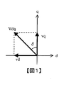
ここで、矩形波電圧位相δを用いてvdとvqを表すと次式の関係になり、これを図示すると図1に示す関係になる。
【数4】
vd=−Vdq・sinδ
【数5】
vq=Vdq・cosδ
数式4,5において、Vdqはdq軸座標系における電圧ベクトルの大きさ(以下、単にdq軸電圧と呼ぶ)であり、矩形波電圧駆動時にはインバーターの直流電源電圧(DCリンク電圧)Vdcを用いて次式のように表せる。
【数6】
Vdq=√(6)・Vdc/π
数式3と数式4から次式が誘導される。
【数7】
iq=Vdq・sinδ/Lqωe
数式7から、高回転速度で定常状態においてはq軸電流iqは電圧位相δに対して正弦波状に変化することが理解される。また、δ=−π/2〜π/2の範囲では、iqはδに対して単調増加であるから、δを操作することによってトルク分電流であるq軸電流を制御することができる。
【0012】
そこで、以下では、数式7により説明したように、電圧位相δを操作してトルク分電流であるq軸電流iqを制御し、モータートルクを調節するようにした一実施の形態を説明する。
【0013】
《発明の第1の実施の形態》
図2に第1の実施の形態の構成を示す。iq*生成器1は、同期モーター8のトルク指令値Te*を入力し、トルク指令値Te*に応じたq軸電流指令値iq*を生成する。このiq*生成器は、例えばトルクと速度を変数としたiq*のマップによって構成される。位相速度演算器10は、レゾルバーなどの位置センサー9により検出したモーター8の機械的な回転角度に基づいてモーター8の電気的な回転速度ωeと電気的な回転角度θeを演算する。dq←3相変換器11は、モーター8の電気的な回転角度θeを用いて電流センサー6、7により検出した3相交流電流iu、ivを次式により座標変換し、q軸電流iqを求める。
【数8】
【数9】
iw=−iu−iv
【0014】
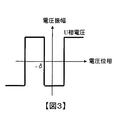
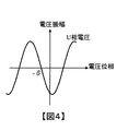
減算器2とPI−q軸電流制御器3は、q軸電流iqのフィードバック制御を行う。まず、減算器9はq軸電流指令値iq*とq軸電流iqとの偏差(iq*−iq)を演算する。次に、PI−q軸電流制御器3は、q軸電流偏差(iq*−iq)が0になるようにPI制御(比例P・積分I制御)を行って矩形波電圧の位相δを求める。なお、q軸電流制御器をPID制御器とし、q軸電流偏差にPID制御を施して矩形波電圧位相δを演算してもよい。矩形波電圧駆動時には、モーター8に印加される矩形波電圧の位相δは図3に示す関係となる。なお、正弦波PWM電圧駆動時には、モーター8に印加される正弦波PWM電圧の位相δは図4に示す関係となる。
【0015】
パルス生成器4は、矩形波電圧位相δとモーター8の電気的回転角度θeとに基づいてモーター8に印加する3相矩形波電圧指令を生成する。ここで、d軸電流とq軸電流を独立に制御する通常のベクトル制御では、次式によりdq軸電圧vd、vqから3相交流電圧vu、vv、vwへの座標変換が行われる。
【数10】
【数11】
【0016】
インバーター5は、パルス生成器4で生成された矩形波電圧指令にしたがってスイッチング素子を駆動し、直流電源(DCリンク)から位相δの3相矩形波電圧を生成してモーター8に印加する。
【0017】
インバーターを矩形波電圧制御で動作させる場合には、正弦波PWM電圧制御で動作させる場合よりも27.3%高い基本波電圧をモーターに印加することができる。また、正弦波に3次高調波を重畳して電圧の利用率を向上させる方法が知られているが、矩形波電圧制御で動作させる場合はこの方法よりも10.3%も高い基本波電圧をモーターに印加することができる。
【0018】
このように、第1の実施の形態によれば、q軸電流指令値iq*にq軸電流iqをフィードバックし、q軸電流偏差(iq*−iq)が0になるようにPI(またはPID)制御を行って矩形波電圧位相δを求め、位相δの3相矩形波電圧をモーターに印加するようにしたので、モーターの正弦波PWM電圧駆動に比べて高い基本波電圧を利用することができ、モーターの高速度領域における出力が増加する。また、トルク電流であるq軸電流を精度よく制御することができ、同期モーターの矩形波電圧駆動時におけるトルク制御精度を改善することができる。
【0019】
上述した第1の実施の形態において、電流センサー6,7が電流検出手段を、位置センサー9、位相速度演算器10およびdq←3相変換器11が電流変換手段を、減算器2およびPI−q軸電流制御器3が位相演算手段を、パルス生成器4およびインバーター5が電力変換手段をそれぞれ構成する。なお、本発明の特徴的な機能を損なわない限り、各構成要素は上記構成に限定されるものではない。
【0020】
《発明の第2の実施の形態》
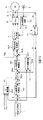
第1の実施の形態では、q軸電流指令値iq*に対してq軸電流iqをフィードバックし、その偏差(iq*−iq)にPI(またはPID)制御を施す例を示したが、制御周期が長くなるとPI(またはPID)制御ゲイン(比例Pゲイン、積分Iゲイン、微分Dゲイン)を高く設定することが難しくなるため、q軸電流制御の応答性が低下する。そこで、この第2の実施の形態では、上述した第1の実施の形態にフィードフォワード補償器を加え、q軸電流制御の応答性を改善する。
【0021】
図5に第2の実施の形態の構成を示す。なお、図2に示す第1の実施の形態の機器と同様な機器に対しては同一の符号を付して説明を省略する。フィードフォワードδ補償器101は、モーター8の電気的角速度ωe、dq軸電圧Vdqおよびq軸電流指令値iq*に基づいて、PI−q軸電流制御器3の矩形波電圧位相δoを補償するための補償分δ’を求める。加算器102は、PI−q軸電流制御器3の矩形波電圧位相δoとδ補償器101の矩形波電圧位相補償分δ’とを加算して矩形波電圧位相δを求める。なお、δ補償器101および加算器102以外の構成は図2に示す第1の実施の形態の構成と同様である。
【0022】
δ補償器101の構成についてさらに詳しく説明する。数式7に示す矩形波電圧位相δ、dq軸電圧Vdq、モーター8の電気的角速度ωeおよびq軸電流iqの関係において、sinδ≒δと近似し、q軸電流指令値iq*、モーター8の電気的角速度ωeおよびdq軸電圧Vdqから、矩形波電圧位相の補償分δ’を次式により求める。
【数12】
δ’=Lqωe・iq*/Vdq
なお、dq軸電圧Vdqはインバーター5の直流電源電圧(DCリンク電圧)Vdcから上記数式6を用いて求められる。
【0023】
減算器2およびPI−q軸電流制御器3は、上述したようにq軸電流偏差(iq*−iq)が0になるようにPI(またはPID)制御を行って矩形波電圧位相δoを求める。加算器102は、PI−q軸電流制御器3の矩形波電圧位相δoとδ補償器101の補償分δ’とを加算して矩形波電圧位相δを求める。以下、第1の実施の形態と同様に、パルス生成器4で矩形波電圧位相δとモーター8の電気的回転角度θeとに基づいてモーター8に印加する3相矩形波電圧指令を生成し、インバーター5により位相δの3相矩形波電圧をモーター8に印加して駆動する。
【0024】
このように、第2の実施の形態によれば、q軸電流指令値iq*にq軸電流iqをフィードバックし、q軸電流偏差(iq*−iq)が0になるようにPI(またはPID)制御を行って矩形波電圧位相δoを求めるとともに、フィードフォワードδ補償器101によりq軸電流指令値iq*、モーター8の電気的角速度ωeおよびdq軸電圧Vdqに基づいて矩形波電圧位相の補償分δ’を求め、矩形波電圧位相δoに補償分δ’を加算して矩形波電圧位相δを求める。そして、位相δの3相矩形波電圧を生成してモーター8に印加するようにしたので、上述した第1の実施の形態の効果に加え、制御周期が長くなってもq軸電流制御の応答性を向上させることができる。
【0025】
上述した第2の実施の形態において、電流センサー6,7が電流検出手段を、位置センサー9、位相速度演算器10およびdq←3相変換器11が電流変換手段を、減算器2およびPI−q軸電流制御器3が位相演算手段を、パルス生成器4およびインバーター5が電力変換手段を、位置センサー9および位相速度演算器10が速度検出手段を、δ補償器101および加算器102が位相補償手段をそれぞれ構成する。なお、本発明の特徴的な機能を損なわない限り、各構成要素は上記構成に限定されるものではない。
【0026】
《発明の第3の実施の形態》
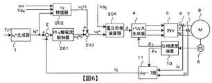
図6に第3の実施の形態の構成を示す。なお、図2および図5に示す機器と同様な機器に対しては同一の符号を付して説明を省略する。
【0027】
この第3の実施の形態では、PI−q軸電流制御器201によりq軸電流偏差(iq*−iq)が0になるようにPI(またはPID)制御を行ってq軸電圧vqoを求めるとともに、フィードフォワードvq補償器202によりq軸電流指令値iq*、モーター8の電気的角速度ωeおよびdq軸電圧Vdqに基づいてq軸電圧補償分vq’を求め、q軸電圧vqoに補償分vq’を加算したq軸電圧vqとdq軸電圧Vdqから矩形波電圧位相δを演算する。
【0028】
PI−q軸電流制御器201は、減算器2により求めたq軸電流指令値iq*とq軸電流iqとの偏差(iq*−iq)にPI(またはPID)制御を施し、q軸電流偏差(iq*−iq)が0になるようなq軸電圧指令値vq*0を求める。フィードフォワードvq補償器202は、q軸電流指令値iq*、モーター8の電気的角速度ωeおよびdq軸電圧Vdqに基づいて、PI−q軸電流制御器201のq軸電圧指令値vq*0を補償するための補償分vq*1を求める。
【0029】
vq補償器202の構成についてさらに詳しく説明する。図1に示すd軸電圧vd、q軸電圧vqおよびdq軸電圧Vdqの関係と数式3から次式が導かれる。
【数13】
vq=√(Vdq2−Lq2iq*2ωe2)
vq補償器202は、数式13により求めたq軸電圧vqをq軸電圧指令値補償分vq*1として出力する。
【0030】
加算器203は、PI−q軸電流制御器201のq軸電圧指令値vq*0とvq補償器202のq軸電圧指令値補償分vq*1とを加算してq軸電圧指令値vq*を求める。電圧位相演算器204は、図1に示す関係からq軸電圧指令値vq*とdq軸電圧Vdqに基づいて矩形波電圧位相δを次式により求める。
【数14】
δ=cos−1(vq*/Vdq)
以下、第1の実施の形態と同様に、パルス生成器4で矩形波電圧位相δとモーター8の電気的回転角度θeとに基づいてモーター8に印加する3相矩形波電圧指令を生成し、インバーター5により位相δの3相矩形波電圧をモーター8に印加して駆動する。
【0031】
このように、第3の実施の形態によれば、q軸電流偏差(iq*−iq)にPI(またはPID)制御を施してq軸電圧指令値vq*0を求めるとともに、フィードフォワードvq補償器202によりq軸電流指令値iq*、モーター8の電気的角速度ωeおよびdq軸電圧Vdqに基づいてq軸電圧指令値補償分vq*1を求め、q軸電圧指令値vq*0に補償分vq*1を加算してq軸電圧指令値vq*を求める。そして、q軸電圧指令値vq*とdq軸電圧Vdqにより矩形波電圧位相δを求め、位相δの3相矩形波電圧をモーター8に印加するようにしたので、上述した第1および第2の実施の形態と同様な効果が得られる上に、q軸電圧指令値vq*0の補償分vq*1をフィードフォワード制御により求めるているので、モーター8の回転速度やq軸電流指令値iq*の変化に対してのq軸電流の応答性を向上させることができる。
【0032】
また、第3の実施の形態によれば、q軸電圧vqとインバーター5の直流電源電圧(DCリンク電圧)Vdcから得られるVdqに基づいて矩形波電圧位相δを求めるので、インバーター5の直流電源電圧(DCリンク電圧)Vdcが変動するような場合にも、q軸電流iqを応答性よく制御することができ、トルク制御の応答性が改善される。
【0033】
さらに、第3の実施の形態では、PI−q軸電流制御器201を、通常のベクトル制御と同様な構成の制御器により構成できるので、通常のベクトル制御を用いたモーター制御装置からの変更、改良が容易である。
【0034】
第3の実施の形態において、電流センサー6,7が電流検出手段を、位置センサー9、位相速度演算器10およびdq←3相変換器11が電流変換手段を、減算器2、PI−q軸電流制御器201および電圧位相演算器204が位相演算手段を、パルス生成器4およびインバーター5が電力変換手段を、位置センサー9および位相速度演算器10が速度検出手段を、vq補償器202および加算器203が位相補償手段をそれぞれ構成する。なお、本発明の特徴的な機能を損なわない限り、各構成要素は上記構成に限定されるものではない。
【0035】
《発明の第4の実施の形態》
上述したように、永久磁石同期モーターのdq軸座標系における回路方程式(数式1)を、高回転速度で且つ定常状態に限定して近似すれば数式3が得られる。数式3を展開すると次式が得られる。
【数15】
vd=−Lqωe・iq
【数16】
vq=Ldωe・id+ωeφ
つまり、数式15から明らかなように、高回転速度時で且つ定常状態においてはd軸電圧vdによりモーターのトルク電流であるq軸電流iqを制御することができる。
【0036】
一方、数式16から明らかなように、高回転速度時で且つ定常状態においてはd軸電流idを小さくすればq軸電圧vqを小さくすることができる。図1に示すd軸電圧vdとq軸電圧vqとの関係から明らかなように、q軸電圧vqを小さくすれば逆にd軸電圧vdを大きくすることができ、数式15の関係からd軸電圧vdを大きくすることはトルク電流であるq軸電流iqを大きくすることになる。つまり、d軸電流idを小さくすることによってトルク分電流であるq軸電流iqを大きくすることができ、これによりトルク制御精度の改善を図ることができる。
【0037】
第4の実施の形態ではこの関係を利用し、q軸電流フィードバック制御系においてq軸電流偏差(iq*−iq)に負の制御ゲインを設定したPI(またはPID)制御を施してd軸電流指令値id*を求め、次にd軸フィードバック制御系においてd軸電流偏差(id*−id)にPI(またはPID)制御を施してd軸電圧指令値vd*を求め、さらにd軸電圧指令値vd*とdq軸電圧Vdqから矩形波電圧位相δを求める。
【0038】
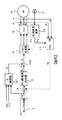
図7に第4の実施の形態の構成を示す。なお、図2、図5および図6に示す機器と同様な機器に対しては同一の符号を付して相違点を中心に説明する。PI−q軸電流制御器301は、q軸電流偏差(iq*−iq)にPI(またはPID)制御を施して得られた出力にゲイン「−1」を乗じてd軸電流指令値id*0を求める。
【0039】
また、q軸電流のフィードバック制御のみではd軸電流指令値id*0に遅れが生じるため、この遅れを補償するためにフィードフォワード補償器であるid*補償器302を設ける。id*補償器302は、q軸電流指令値iq*、モーター8の電気的回転速度ωeおよびdq軸電圧Vdqに基づいてd軸電流指令値id*0の補償分id*1を求める。図1に示すd軸電圧vd、q軸電圧vqおよびdq軸電圧Vdqの関係と数式3から次式が導かれる。
【数17】
id=1/Ld{−φ+√(Vdq2/ωe2−Lq2iq2)}
id*補償器302は、数式17のq軸電流iqにその指令値iq*を代入し、演算結果のd軸電流idをd軸電流指令値補償分id*1として出力する。
【0040】
加算器303は、PI−q軸電流制御器301のd軸電流指令値id*0とid*補償器302のd軸電流指令値補償分id*1とを加算してd軸電流指令値id*を求める。
【0041】
減算器304とPI−d軸電流制御器305は、d軸電流idのフィードバック制御を行う。なお、d軸電流idは、q軸電流iqとともにdq←3相変換器11によってモーター8の電気的な回転角度θeおよび電流センサー6,7により検出した3相交流電流iu、ivを数式8により座標変換して求められる。まず、減算器304はd軸電流指令値id*とd軸電流idとの偏差(id*−id)を演算する。次に、PI−d軸電流制御器305は、d軸電流偏差(id*−id)が0になるようにPI(またはPID)制御を行ってd軸電圧指令値vd*0を求める。
【0042】
d軸電流制御ではq軸電流によって発生する電圧が外乱項として働くため、この外乱電圧を補償するために非干渉制御器306を設ける。非干渉制御器306は、q軸電流指令値iq*とモーター8の電気的角速度ωeに基づいて数式15によりd軸電圧vdを求め、d軸電圧指令値vd*0の補償分vd*1として出力する。加算器308は、PI−d軸電流制御器305のd軸電圧指令値vd*0と非干渉制御器306のd軸電圧補償分vd*1を加算してd軸電圧指令値vd*を求める。
【0043】
電圧位相演算器307は、図1に示す関係からd軸電圧指令値vd*とdq軸電圧Vdqに基づいて矩形波電圧位相δを次式により求める。
【数18】
δ=sin−1(−vd*/Vdq)
以下、第1の実施の形態と同様に、パルス生成器4で矩形波電圧位相δとモーター8の電気的回転角度θeとに基づいてモーター8に印加する3相矩形波電圧指令を生成し、インバーター5により位相δの3相矩形波電圧をモーター8に印加して駆動する。
【0044】
この第4の実施の形態によれば、矩形波電圧の位相δを制御することによってq軸電流iqをその指令値iq*に追従させることができ、モータートルクを精度よく制御することができるとともに、モータートルクの応答性を向上させることができる。
【0045】
また、q軸電流iqに対するd軸電流idの変化量と、d軸電流idに対するq軸電流iqの変化量を比較すると、後者の方が小さくなる。このことから、検出電流にノイズが含まれる場合や電流リップルがある場合に、d軸電流idをフィードバック制御することによって定常時のq軸電流iqを安定に精度よく保つことができる。一方で、d軸電流idの変化に対してのq軸電流iqの変化量が小さいため、q軸電流iqの応答を速くする場合には上述したid*補償器302や非干渉制御器306が必要になる。
【0046】
また、第4の実施の形態で用いたPI−d軸電流制御器305や非干渉制御器306は、通常のベクトル制御に用いられる制御器と同様なものを用いることができるため、通常のベクトル制御を用いたモーター制御装置から第4の実施の形態の矩形波電圧駆動への変更、改良は容易である。
【0047】
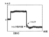
図8は、上述した第4の実施の形態によるトルク応答のシミュレーション結果を示す。このシミュレーション結果から明らかなように、モータートルクにトルクリップルが含まれているが、モータートルクがその指令値に精度よく追従していることがわかる。
【0048】
第4の実施の形態において、電流センサー6,7が電流検出手段を、位置センサー9、位相速度演算器10およびdq←3相変換器11が電流変換手段を、減算器2、PI−q軸電流制御器301、減算器304、PI−d軸電流制御器305および電圧位相演算器307が位相演算手段を、パルス生成器4およびインバーター5が電力変換手段を、位置センサー9および位相速度演算器10が速度検出手段を、id*補償器302および加算器303が電流補償手段を、非干渉制御器306および加算器308が電圧補償手段をそれぞれ構成する。なお、本発明の特徴的な機能を損なわない限り、各構成要素は上記構成に限定されるものではない。
【0049】
なお、上述した一実施の形態では、dq軸座標系におけるモーターの回路方程式を高回転速度でかつ定常状態に限定して近似し、近似式(数式3)に基づいて矩形波電圧駆動を行う例を示した。モーターを上述した矩形波電圧のみにより駆動してもよいが、低回転速度時には従来の正弦波PWM電圧駆動に切り換えてモーターを駆動制御するのが望ましい。正弦波PWM電圧駆動制御と、正弦波PWM電圧駆動と矩形波電圧駆動との切り換え制御についてはすでにいろいろな方法が提案されているので、それらの制御方法によるものとする。
【図面の簡単な説明】
【図1】 dq軸電圧vd、vqと矩形波電圧位相δとの関係を示す図である。
【図2】 第1の実施の形態の構成を示す図である。
【図3】 U相矩形波電圧波形を示す図である。
【図4】 U相正弦波PWM電圧波形を示す図である。
【図5】 第2の実施の形態の構成を示す図である。
【図6】 第3の実施の形態の構成を示す図である。
【図7】 第4の実施の形態の構成を示す図である。
【図8】 第4の実施の形態によるトルク応答のシミュレーション結果を示す図である。
【符号の説明】
1 iq*生成器
2 減算器
3 PI−q軸電流制御器
4 パルス生成器
5 インバーター
6、7 電流センサー
8 3相同期モーター
9 位置センサー
10 位相速度演算器
11 dq←3相変換器
101 δ補償器
102 加算器
201 PI−q軸電流制御器
202 vq補償器
203 加算器
204 電圧位相演算器
301 PI−q軸電流制御器
302 id*補償器
303 加算器
304 減算器
305 PI−d軸電流制御器
306 非干渉制御器
307 電圧位相演算器
308 加算器[0001]
BACKGROUND OF THE INVENTION
The present invention relates to an AC motor control device.
[0002]
[Prior art]
When applying voltage to an AC motor using an inverter, applying a pulse of rectangular wave voltage instead of sinusoidal PWM voltage can increase the peak value of the fundamental wave voltage, and the motor output in the high rotation speed range. Can be increased. During such rectangular wave voltage driving, the phase of the voltage applied to the motor can be controlled, but the amplitude of the applied voltage is determined by the DC power supply voltage (DC link voltage) of the inverter, and the motor torque cannot be controlled accurately.
[0003]
In order to solve such a problem at the time of rectangular wave voltage driving, a torque estimator is used to estimate the motor torque, and by controlling the voltage phase based on the deviation between the torque command value and the estimated value, the
[0004]
Prior art documents related to the invention of this application include the following.
[Patent Document 1]
Japanese Patent Laid-Open No. 2000-050689
[Problems to be solved by the invention]
However, in the above-described conventional motor control device, the estimated value is fed back to the command value of the motor torque based on the relationship between the motor torque and the voltage phase in the steady state, and thus the torque control is performed. It is difficult to increase responsiveness. In addition, since the torque estimator estimates the motor torque from the relationship between the electric power, the machine output, and the loss, it is difficult to improve the torque control accuracy because an accurate estimated value cannot be obtained.
[0006]
The present invention provides a motor control device with improved torque control performance when a synchronous motor is driven by a rectangular wave voltage.
[0007]
[Means for Solving the Problems]
In the present invention, the current flowing through the three-phase synchronous motor is coordinate-converted into a dq-axis current in a dq-axis coordinate system that rotates in synchronization with the motor rotation, and based on a q-axis current deviation between the q-axis current command value and the q-axis current. The phase of the rectangular wave voltage is calculated, and a rectangular wave voltage is generated from the DC power source according to this phase and applied to the three-phase synchronous motor for driving.
[0008]
【The invention's effect】
According to the present invention, it is possible to improve torque control performance during rectangular wave voltage driving.
[0009]
DETAILED DESCRIPTION OF THE INVENTION
The circuit equation in the dq axis coordinate system rotating in synchronization with the rotation of the permanent magnet synchronous motor can be expressed as the following equation.
[Expression 1]
[0010]
Considering a steady state in which the motor load, that is, the current is substantially constant,
[Expression 2]
[Equation 3]
Here, when vd and vq are expressed using the rectangular wave voltage phase δ, the relationship is expressed by the following equation, and the relationship shown in FIG. 1 is illustrated.
[Expression 4]
vd = -Vdq · sinδ
[Equation 5]
vq = Vdq ・ cosδ
In
[Formula 6]
Vdq = √ (6) · Vdc / π
From Equation 3 and
[Expression 7]
iq = Vdq · sinδ / Lqωe
From
[0012]
Therefore, in the following, an embodiment in which the motor torque is adjusted by operating the voltage phase δ to control the q-axis current iq, which is a torque-divided current, as described with
[0013]
<< First Embodiment of the Invention >>
FIG. 2 shows the configuration of the first embodiment. The iq * generator 1 receives the torque command value Te * of the
[Equation 8]
[Equation 9]
iw = -iu-iv
[0014]
The
[0015]
The
[Expression 10]
## EQU11 ##
[0016]
The inverter 5 drives the switching element in accordance with the rectangular wave voltage command generated by the
[0017]
When the inverter is operated with rectangular wave voltage control, a fundamental wave voltage 27.3% higher than that when operated with sine wave PWM voltage control can be applied to the motor. In addition, a method of improving the voltage utilization factor by superimposing a third harmonic on a sine wave is known, but a fundamental wave voltage that is 10.3% higher than this method when operated by rectangular wave voltage control. Can be applied to the motor.
[0018]
Thus, according to the first embodiment, PI (or PID) is fed so that the q-axis current deviation (iq * −iq) becomes zero by feeding back the q-axis current iq to the q-axis current command value iq *. ) A rectangular wave voltage phase δ is obtained by performing control, and a three-phase rectangular wave voltage having a phase δ is applied to the motor, so that a higher fundamental wave voltage can be used compared to the sine wave PWM voltage driving of the motor. This increases the output in the high speed region of the motor. Further, the q-axis current that is the torque current can be controlled with high accuracy, and the torque control accuracy when the synchronous motor is driven with the rectangular wave voltage can be improved.
[0019]
In the first embodiment described above, the
[0020]
<< Second Embodiment of the Invention >>
In the first embodiment, an example in which the q-axis current iq is fed back to the q-axis current command value iq * and PI (or PID) control is performed on the deviation (iq * −iq) has been described. When the period is long, it becomes difficult to set a PI (or PID) control gain (proportional P gain, integral I gain, differential D gain) high, and the responsiveness of the q-axis current control decreases. Therefore, in the second embodiment, a feedforward compensator is added to the first embodiment described above to improve the responsiveness of the q-axis current control.
[0021]
FIG. 5 shows the configuration of the second embodiment. In addition, the same code | symbol is attached | subjected to the apparatus similar to the apparatus of 1st Embodiment shown in FIG. 2, and description is abbreviate | omitted. The feedforward δ compensator 101 compensates for the rectangular wave voltage phase δo of the PI-q axis current controller 3 based on the electrical angular velocity ωe of the
[0022]
The configuration of the δ compensator 101 will be described in more detail. In the relationship between the rectangular wave voltage phase δ, the dq axis voltage Vdq, the electrical angular velocity ωe of the
[Expression 12]
δ '= Lqωe · iq * / Vdq
The dq axis voltage Vdq is obtained from the DC power supply voltage (DC link voltage) Vdc of the inverter 5 using the
[0023]
The
[0024]
As described above, according to the second embodiment, PI (or PID) is fed so that the q-axis current deviation (iq * −iq) becomes zero by feeding back the q-axis current iq to the q-axis current command value iq *. ) To obtain the rectangular wave voltage phase δo by performing control, and the feedforward δ compensator 101 compensates for the rectangular wave voltage phase based on the q-axis current command value iq * , the electrical angular velocity ωe of the
[0025]
In the second embodiment described above, the
[0026]
<< Third Embodiment of the Invention >>
FIG. 6 shows the configuration of the third embodiment. 2 and 5 are denoted by the same reference numerals and description thereof is omitted.
[0027]
In the third embodiment, PI (or PID) control is performed by the PI-q-axis
[0028]
The PI-q-axis
[0029]
The configuration of the
[Formula 13]
vq = √ (Vdq 2 −Lq 2 iq * 2 ωe 2 )
The
[0030]
The
[Expression 14]
δ = cos −1 (vq * / Vdq)
Hereinafter, similarly to the first embodiment, the
[0031]
As described above, according to the third embodiment, the q-axis current deviation (iq * −iq) is subjected to PI (or PID) control to obtain the q-axis voltage
[0032]
According to the third embodiment, since the rectangular wave voltage phase δ is obtained based on the q-axis voltage vq and Vdq obtained from the DC power supply voltage (DC link voltage) Vdc of the inverter 5, the DC power supply of the inverter 5 is used. Even when the voltage (DC link voltage) Vdc fluctuates, the q-axis current iq can be controlled with good responsiveness, and the responsiveness of torque control is improved.
[0033]
Furthermore, in the third embodiment, since the PI-q axis
[0034]
In the third embodiment, the
[0035]
<< Fourth Embodiment of the Invention >>
As described above, Equation (3) can be obtained by approximating the circuit equation (Equation 1) in the dq axis coordinate system of the permanent magnet synchronous motor at a high rotational speed and limited to a steady state. When Formula 3 is expanded, the following formula is obtained.
[Expression 15]
vd = -Lqωe · iq
[Expression 16]
vq = Ldωe ・ id + ωeφ
That is, as is clear from Equation 15, the q-axis current iq that is the torque current of the motor can be controlled by the d-axis voltage vd at a high rotational speed and in a steady state.
[0036]
On the other hand, as is clear from Equation 16, the q-axis voltage vq can be reduced by reducing the d-axis current id at a high rotational speed and in a steady state. As is clear from the relationship between the d-axis voltage vd and the q-axis voltage vq shown in FIG. 1, if the q-axis voltage vq is decreased, the d-axis voltage vd can be increased. Increasing the voltage vd increases the q-axis current iq that is the torque current. That is, by reducing the d-axis current id, the q-axis current iq, which is the torque component current, can be increased, thereby improving the torque control accuracy.
[0037]
In the fourth embodiment, this relationship is used, and in the q-axis current feedback control system, PI (or PID) control in which a negative control gain is set to the q-axis current deviation (iq * −iq) is performed to perform d-axis current. The command value id * is obtained, and then the d-axis current deviation (id * -id) is subjected to PI (or PID) control in the d-axis feedback control system to obtain the d-axis voltage command value vd *. A rectangular wave voltage phase δ is obtained from the value vd * and the dq axis voltage Vdq.
[0038]
FIG. 7 shows the configuration of the fourth embodiment. In addition, the same code | symbol is attached | subjected to the apparatus similar to the apparatus shown in FIG.2, FIG.5 and FIG.6, and it demonstrates centering on difference. The PI-q-axis
[0039]
Further, since only the feedback control of the q-axis current causes a delay in the d-axis current
[Expression 17]
id = 1 / Ld {-φ + √ (
The id * compensator 302 substitutes the command value iq * for the q-axis current iq in Expression 17, and outputs the calculated d-axis current id as the d-axis current command value
[0040]
The adder 303 adds the d-axis current
[0041]
The
[0042]
In the d-axis current control, the voltage generated by the q-axis current works as a disturbance term. Therefore, a
[0043]
The
[Formula 18]
δ = sin −1 (−vd * / Vdq)
Hereinafter, similarly to the first embodiment, the
[0044]
According to the fourth embodiment, the q-axis current iq can be made to follow the command value iq * by controlling the phase δ of the rectangular wave voltage, and the motor torque can be accurately controlled. The responsiveness of the motor torque can be improved.
[0045]
Further, when the change amount of the d-axis current id with respect to the q-axis current iq is compared with the change amount of the q-axis current iq with respect to the d-axis current id, the latter is smaller. From this, when the detected current includes noise or there is a current ripple, the steady-state q-axis current iq can be stably and accurately maintained by feedback control of the d-axis current id. On the other hand, since the amount of change in the q-axis current iq with respect to the change in the d-axis current id is small, the id * compensator 302 and the
[0046]
In addition, since the PI-d axis
[0047]
FIG. 8 shows a simulation result of torque response according to the fourth embodiment described above. As is apparent from the simulation results, the torque ripple is included in the motor torque, but it can be seen that the motor torque accurately follows the command value.
[0048]
In the fourth embodiment, the
[0049]
In the above-described embodiment, the motor circuit equation in the dq-axis coordinate system is approximated to a high rotational speed and limited to a steady state, and rectangular wave voltage driving is performed based on the approximate equation (Equation 3). showed that. Although the motor may be driven only by the rectangular wave voltage described above, it is desirable to switch the motor to the conventional sine wave PWM voltage driving and control the driving at a low rotational speed. Since various methods have already been proposed for the sine wave PWM voltage drive control and the switching control between the sine wave PWM voltage drive and the rectangular wave voltage drive, these control methods are used.
[Brief description of the drawings]
FIG. 1 is a diagram showing a relationship between dq-axis voltages vd and vq and a rectangular wave voltage phase δ.
FIG. 2 is a diagram showing a configuration of the first exemplary embodiment.
FIG. 3 is a diagram showing a U-phase rectangular wave voltage waveform.
FIG. 4 is a diagram showing a U-phase sine wave PWM voltage waveform;
FIG. 5 is a diagram showing a configuration of a second exemplary embodiment.
FIG. 6 is a diagram showing a configuration of a third exemplary embodiment.
FIG. 7 is a diagram showing a configuration of a fourth exemplary embodiment.
FIG. 8 is a diagram illustrating a simulation result of torque response according to the fourth embodiment.
[Explanation of symbols]
1 iq * generator 2 subtractor 3 PI-q axis
Claims (8)
前記同期モーターに流れる電流を検出する電流検出手段と、
前記電流検出手段により検出された電流を前記モーターの回転に同期して回転するdq軸座標系のdq軸電流に座標変換する電流変換手段と、
q軸電流指令値と前記q軸電流とのq軸電流偏差に基づいて前記矩形波電圧の位相を演算する位相演算手段と、
前記位相演算手段で演算された位相にしたがって直流電源から矩形波電圧を生成する電力変換手段とを備えることを特徴とするモーター制御装置。In a motor control device that drives by applying a three-phase rectangular wave voltage to a three-phase synchronous motor,
Current detecting means for detecting a current flowing through the synchronous motor;
Current conversion means for converting the current detected by the current detection means into a dq axis current of a dq axis coordinate system that rotates in synchronization with the rotation of the motor;
phase calculating means for calculating a phase of the rectangular wave voltage based on a q-axis current deviation between a q-axis current command value and the q-axis current;
A motor control device comprising: power conversion means for generating a rectangular wave voltage from a DC power source according to the phase calculated by the phase calculation means.
前記位相演算手段は、前記q軸電流偏差が0となるようにPI制御またはPID制御を行って矩形波電圧の位相を演算することを特徴とするモーター制御装置。The motor control device according to claim 1,
The motor controller according to claim 1, wherein the phase calculator calculates the phase of the rectangular wave voltage by performing PI control or PID control so that the q-axis current deviation becomes zero.
前記モーターの回転速度を検出する速度検出手段と、
前記q軸電流指令値、前記電力変換手段の直流電源電圧および前記モーター回転速度に基づいて前記矩形波電圧の位相を補償する位相補償手段とを備えることを特徴とするモーター制御装置。The motor control device according to claim 2,
Speed detecting means for detecting the rotational speed of the motor;
A motor control apparatus comprising: phase compensation means for compensating a phase of the rectangular wave voltage based on the q-axis current command value, a DC power supply voltage of the power conversion means, and the motor rotation speed.
前記位相演算手段は、前記q軸電流偏差が0となるようにPI制御またはPID制御を行ってq軸電圧指令値を演算し、前記q軸電圧指令値と前記電力変換手段の直流電源電圧とに基づいて位相を演算することを特徴とするモーター制御装置。The motor control device according to claim 1,
The phase calculating means calculates a q-axis voltage command value by performing PI control or PID control so that the q-axis current deviation becomes zero, and calculates the q-axis voltage command value and the DC power supply voltage of the power conversion means. A motor control device that calculates a phase based on the motor.
前記モーターの回転速度を検出する速度検出手段と、
前記q軸電流指令値、前記電力変換手段の直流電源電圧および前記モーター回転速度に基づいて前記q軸電圧指令値を補償する電圧補償手段とを備えることを特徴とするモーター制御装置。The motor control device according to claim 4, wherein
Speed detecting means for detecting the rotational speed of the motor;
A motor control device comprising: a voltage compensation unit that compensates the q-axis voltage command value based on the q-axis current command value, a DC power supply voltage of the power conversion unit, and the motor rotation speed.
前記位相演算手段は、前記q軸電流偏差が0となるようにPI制御またはPID制御を行ってd軸電流指令値を演算する手段と、前記d軸電流指令値と前記d軸電流に基づいてd軸電圧指令値を演算する手段と、前記d軸電圧指令値と前記電力変換手段の直流電源電圧とに基づいて前記矩形波電圧の位相を演算する手段とを備えることを特徴とするモーター制御装置。The motor control device according to claim 1,
The phase calculating means calculates the d-axis current command value by performing PI control or PID control so that the q-axis current deviation becomes zero, and based on the d-axis current command value and the d-axis current. Motor control comprising: means for calculating a d-axis voltage command value; and means for calculating a phase of the rectangular wave voltage based on the d-axis voltage command value and a DC power supply voltage of the power conversion means. apparatus.
前記モーターの回転速度を検出する速度検出手段と、
前記q軸電流指令値、前記電力変換手段の直流電源電圧および前記モーター回転速度に基づいて前記d軸電流指令値を補償する電流補償手段とを備えることを特徴とするモーター制御装置。The motor control device according to claim 6,
Speed detecting means for detecting the rotational speed of the motor;
A motor control device comprising: a current compensation means for compensating the d-axis current command value based on the q-axis current command value, a DC power supply voltage of the power conversion means, and the motor rotation speed.
前記モーターの回転速度を検出する速度検出手段と、
前記q軸電流指令値と前記モーター回転速度とに基づいて前記d軸電圧指令値を補償する電圧補償手段とを備えることを特徴とするモーター制御装置。The motor control device according to claim 6,
Speed detecting means for detecting the rotational speed of the motor;
A motor control device comprising: voltage compensation means for compensating the d-axis voltage command value based on the q-axis current command value and the motor rotation speed.
Priority Applications (3)
| Application Number | Priority Date | Filing Date | Title |
|---|---|---|---|
| JP2003078181A JP3783695B2 (en) | 2003-03-20 | 2003-03-20 | Motor control device |
| US10/779,612 US6927551B2 (en) | 2003-03-20 | 2004-02-18 | Motor control apparatus and motor control method |
| EP04004373.9A EP1460758B1 (en) | 2003-03-20 | 2004-02-26 | Vector control method and apparatus |
Applications Claiming Priority (1)
| Application Number | Priority Date | Filing Date | Title |
|---|---|---|---|
| JP2003078181A JP3783695B2 (en) | 2003-03-20 | 2003-03-20 | Motor control device |
Publications (2)
| Publication Number | Publication Date |
|---|---|
| JP2004289926A JP2004289926A (en) | 2004-10-14 |
| JP3783695B2 true JP3783695B2 (en) | 2006-06-07 |
Family
ID=32821389
Family Applications (1)
| Application Number | Title | Priority Date | Filing Date |
|---|---|---|---|
| JP2003078181A Expired - Fee Related JP3783695B2 (en) | 2003-03-20 | 2003-03-20 | Motor control device |
Country Status (3)
| Country | Link |
|---|---|
| US (1) | US6927551B2 (en) |
| EP (1) | EP1460758B1 (en) |
| JP (1) | JP3783695B2 (en) |
Families Citing this family (22)
| Publication number | Priority date | Publication date | Assignee | Title |
|---|---|---|---|---|
| US20040251860A1 (en) * | 2003-01-09 | 2004-12-16 | Mehrdad Ehsani | Advanced sensorless drive technique for brushless DC motors |
| JP4422567B2 (en) * | 2004-06-30 | 2010-02-24 | 株式会社日立製作所 | Motor drive device, electric actuator, and electric power steering device |
| US6967461B1 (en) * | 2004-08-31 | 2005-11-22 | Hamilton Sundstrand Corporation | North-south pole determination for carrier injection sensorless position sensing systems |
| JP2006121855A (en) * | 2004-10-25 | 2006-05-11 | Nissan Motor Co Ltd | Ac motor control device |
| US7932693B2 (en) * | 2005-07-07 | 2011-04-26 | Eaton Corporation | System and method of controlling power to a non-motor load |
| JP4640004B2 (en) * | 2005-07-11 | 2011-03-02 | 日産自動車株式会社 | Inverter control method |
| JP2007159368A (en) * | 2005-12-08 | 2007-06-21 | Toyota Motor Corp | Control unit of motor drive system |
| JP2007159353A (en) * | 2005-12-08 | 2007-06-21 | Mitsubishi Electric Corp | Field winding type synchronous generator motor |
| JP4674568B2 (en) * | 2006-05-10 | 2011-04-20 | 株式会社豊田自動織機 | Motor inverter |
| US7622877B2 (en) * | 2007-03-13 | 2009-11-24 | Gm Global Technology Operations, Inc. | Method and system for controlling permanent magnet AC machines |
| US7960940B2 (en) * | 2007-07-10 | 2011-06-14 | Jtekt Corporation | Motor control device |
| US8390240B2 (en) * | 2007-08-06 | 2013-03-05 | GM Global Technology Operations LLC | Absolute position sensor for field-oriented control of an induction motor |
| JP5293159B2 (en) * | 2008-12-22 | 2013-09-18 | トヨタ自動車株式会社 | AC motor control system |
| JP5407322B2 (en) | 2008-12-22 | 2014-02-05 | トヨタ自動車株式会社 | AC motor control system |
| JP5574790B2 (en) | 2010-04-08 | 2014-08-20 | オムロンオートモーティブエレクトロニクス株式会社 | Motor drive device |
| JP5780022B2 (en) * | 2011-07-05 | 2015-09-16 | トヨタ自動車株式会社 | AC motor control apparatus and control method |
| KR101382749B1 (en) * | 2012-04-13 | 2014-04-08 | 현대자동차주식회사 | Method for correcting resolver offset |
| JP5633551B2 (en) * | 2012-11-05 | 2014-12-03 | 株式会社安川電機 | AC motor control device |
| JP5585643B2 (en) * | 2012-12-14 | 2014-09-10 | ダイキン工業株式会社 | Active filter control device |
| CN104035462B (en) * | 2014-05-30 | 2016-09-28 | 华为技术有限公司 | A kind of power control method and equipment |
| JP2018060289A (en) * | 2016-10-03 | 2018-04-12 | オムロン株式会社 | Trajectory generation apparatus, control method, control program and recording medium for trajectory generation apparatus |
| CN113467229B (en) * | 2021-07-13 | 2023-07-21 | 南京信息职业技术学院 | Alternating current servo driving method |
Family Cites Families (20)
| Publication number | Priority date | Publication date | Assignee | Title |
|---|---|---|---|---|
| JPS6038954B2 (en) * | 1980-12-30 | 1985-09-03 | ファナック株式会社 | Induction motor drive system |
| JPS583586A (en) * | 1981-06-26 | 1983-01-10 | Nippon Steel Corp | Torque controller for thyristor motor |
| JPH0984400A (en) * | 1995-09-14 | 1997-03-28 | Fanuc Ltd | Method for controlling current of servomotor |
| JP3674741B2 (en) * | 1998-04-15 | 2005-07-20 | 富士電機システムズ株式会社 | Control device for permanent magnet synchronous motor |
| JP3746377B2 (en) * | 1998-07-24 | 2006-02-15 | トヨタ自動車株式会社 | AC motor drive control device |
| JP3396440B2 (en) * | 1999-02-08 | 2003-04-14 | 株式会社日立製作所 | Control device for synchronous motor |
| JP2001008482A (en) * | 1999-06-22 | 2001-01-12 | Hitachi Ltd | Control system and control of motor |
| JP3454210B2 (en) * | 1999-11-30 | 2003-10-06 | 株式会社日立製作所 | Position sensorless control method for synchronous motor |
| JP4526628B2 (en) * | 2000-01-06 | 2010-08-18 | 本田技研工業株式会社 | AC motor control device |
| EP1211798B1 (en) * | 2000-11-22 | 2018-01-10 | Nissan Motor Co., Ltd. | Motor control apparatus and motor control method |
| JP4671521B2 (en) * | 2001-03-27 | 2011-04-20 | 東芝エレベータ株式会社 | Electric motor control device |
| JP3755424B2 (en) * | 2001-05-31 | 2006-03-15 | トヨタ自動車株式会社 | AC motor drive control device |
| JP3867518B2 (en) * | 2001-06-06 | 2007-01-10 | 株式会社日立製作所 | Sensorless control system for synchronous motor |
| JP3627683B2 (en) * | 2001-06-29 | 2005-03-09 | 日産自動車株式会社 | Motor control device |
| CN1212701C (en) * | 2001-07-13 | 2005-07-27 | 三菱电机株式会社 | Speed control device for AG electric motor |
| JP3559258B2 (en) * | 2001-07-30 | 2004-08-25 | 三菱電機株式会社 | Steering control device |
| JP3582505B2 (en) * | 2001-09-10 | 2004-10-27 | 日産自動車株式会社 | Motor control device |
| JP3722048B2 (en) * | 2001-11-15 | 2005-11-30 | 日産自動車株式会社 | Motor control device |
| JP3812739B2 (en) * | 2002-05-28 | 2006-08-23 | 三菱電機株式会社 | Motor abnormality detection device and electric power steering control device |
| JP3928575B2 (en) * | 2003-04-07 | 2007-06-13 | 日産自動車株式会社 | Motor control device |
-
2003
- 2003-03-20 JP JP2003078181A patent/JP3783695B2/en not_active Expired - Fee Related
-
2004
- 2004-02-18 US US10/779,612 patent/US6927551B2/en not_active Expired - Lifetime
- 2004-02-26 EP EP04004373.9A patent/EP1460758B1/en not_active Expired - Lifetime
Also Published As
| Publication number | Publication date |
|---|---|
| EP1460758B1 (en) | 2018-04-11 |
| US20040183496A1 (en) | 2004-09-23 |
| US6927551B2 (en) | 2005-08-09 |
| EP1460758A2 (en) | 2004-09-22 |
| EP1460758A3 (en) | 2006-03-01 |
| JP2004289926A (en) | 2004-10-14 |
Similar Documents
| Publication | Publication Date | Title |
|---|---|---|
| JP3783695B2 (en) | Motor control device | |
| JP3746377B2 (en) | AC motor drive control device | |
| JP3661642B2 (en) | Motor control device and control method thereof | |
| JP6617500B2 (en) | Electric power steering control method, electric power steering control device, electric power steering device and vehicle | |
| JP4631672B2 (en) | Magnetic pole position estimation method, motor speed estimation method, and motor control apparatus | |
| JP2008086129A (en) | Ac motor controller and constant measurement apparatus | |
| WO2008004316A1 (en) | Vector control apparatus for induction motor, vector control method for induction motor, and drive control apparatus for induction motor | |
| JP2004343963A (en) | Control device for brushless dc motor | |
| JP2011147287A (en) | Estimation device of magnetic pole position of motor | |
| JP5330652B2 (en) | Permanent magnet motor control device | |
| JP2004064909A (en) | Motor control device | |
| JP4402600B2 (en) | Synchronous motor drive system and synchronous motor drive method | |
| JP5165545B2 (en) | Electric motor magnetic pole position estimation device | |
| WO2022009599A1 (en) | Motor control device and motor control method | |
| JP2004289927A (en) | Motor controller | |
| JP2005229717A (en) | Current sensorless-control method and device of synchronous motor | |
| JP3939481B2 (en) | AC motor control device | |
| KR20080019131A (en) | Electric motor using a voltage control device and method for controlling thereof | |
| JP5082216B2 (en) | Rotation detection device for turbocharger with electric motor and rotation detection method for turbocharger with electric motor | |
| JP2006121855A (en) | Ac motor control device | |
| JP5186352B2 (en) | Electric motor magnetic pole position estimation device | |
| JP2021022965A (en) | Driving device of induction motor, driving method, and electric vehicle | |
| JP7529463B2 (en) | POWER CONVERSION DEVICE, POWER CONVERSION METHOD, AND PROGRAM | |
| JP2020036513A (en) | Motor controller | |
| JP4526628B2 (en) | AC motor control device |
Legal Events
| Date | Code | Title | Description |
|---|---|---|---|
| A977 | Report on retrieval |
Free format text: JAPANESE INTERMEDIATE CODE: A971007 Effective date: 20051128 |
|
| A131 | Notification of reasons for refusal |
Free format text: JAPANESE INTERMEDIATE CODE: A131 Effective date: 20051206 |
|
| A521 | Written amendment |
Free format text: JAPANESE INTERMEDIATE CODE: A523 Effective date: 20060201 |
|
| TRDD | Decision of grant or rejection written | ||
| A01 | Written decision to grant a patent or to grant a registration (utility model) |
Free format text: JAPANESE INTERMEDIATE CODE: A01 Effective date: 20060221 |
|
| A61 | First payment of annual fees (during grant procedure) |
Free format text: JAPANESE INTERMEDIATE CODE: A61 Effective date: 20060306 |
|
| R150 | Certificate of patent or registration of utility model |
Ref document number: 3783695 Country of ref document: JP Free format text: JAPANESE INTERMEDIATE CODE: R150 Free format text: JAPANESE INTERMEDIATE CODE: R150 |
|
| FPAY | Renewal fee payment (event date is renewal date of database) |
Free format text: PAYMENT UNTIL: 20090324 Year of fee payment: 3 |
|
| FPAY | Renewal fee payment (event date is renewal date of database) |
Free format text: PAYMENT UNTIL: 20100324 Year of fee payment: 4 |
|
| FPAY | Renewal fee payment (event date is renewal date of database) |
Free format text: PAYMENT UNTIL: 20100324 Year of fee payment: 4 |
|
| FPAY | Renewal fee payment (event date is renewal date of database) |
Free format text: PAYMENT UNTIL: 20110324 Year of fee payment: 5 |
|
| FPAY | Renewal fee payment (event date is renewal date of database) |
Free format text: PAYMENT UNTIL: 20110324 Year of fee payment: 5 |
|
| FPAY | Renewal fee payment (event date is renewal date of database) |
Free format text: PAYMENT UNTIL: 20120324 Year of fee payment: 6 |
|
| FPAY | Renewal fee payment (event date is renewal date of database) |
Free format text: PAYMENT UNTIL: 20130324 Year of fee payment: 7 |
|
| FPAY | Renewal fee payment (event date is renewal date of database) |
Free format text: PAYMENT UNTIL: 20130324 Year of fee payment: 7 |
|
| LAPS | Cancellation because of no payment of annual fees |