JP3783374B2 - Toroidal continuously variable transmission - Google Patents

Toroidal continuously variable transmission Download PDF

Info

Publication number
JP3783374B2
JP3783374B2 JP31346597A JP31346597A JP3783374B2 JP 3783374 B2 JP3783374 B2 JP 3783374B2 JP 31346597 A JP31346597 A JP 31346597A JP 31346597 A JP31346597 A JP 31346597A JP 3783374 B2 JP3783374 B2 JP 3783374B2
Authority
JP
Japan
Prior art keywords
input
input side
continuously variable
output side
variable transmission
Prior art date
Legal status (The legal status is an assumption and is not a legal conclusion. Google has not performed a legal analysis and makes no representation as to the accuracy of the status listed.)
Expired - Fee Related
Application number
JP31346597A
Other languages
Japanese (ja)
Other versions
JPH11148543A (en
Inventor
尚 今西
伸夫 後藤
誠 藤波
寛 加藤
Current Assignee (The listed assignees may be inaccurate. Google has not performed a legal analysis and makes no representation or warranty as to the accuracy of the list.)
NSK Ltd
Original Assignee
NSK Ltd
Priority date (The priority date is an assumption and is not a legal conclusion. Google has not performed a legal analysis and makes no representation as to the accuracy of the date listed.)
Filing date
Publication date
Application filed by NSK Ltd filed Critical NSK Ltd
Priority to JP31346597A priority Critical patent/JP3783374B2/en
Priority to US09/188,711 priority patent/US6074324A/en
Priority to DE19861194A priority patent/DE19861194B4/en
Priority to DE19852249A priority patent/DE19852249C2/en
Priority to DE19861271A priority patent/DE19861271B4/en
Publication of JPH11148543A publication Critical patent/JPH11148543A/en
Application granted granted Critical
Publication of JP3783374B2 publication Critical patent/JP3783374B2/en
Anticipated expiration legal-status Critical
Expired - Fee Related legal-status Critical Current

Links

Images

Description

【0001】
【発明の属する技術分野】
この発明に係るトロイダル型無段変速機は、例えば自動車用の自動変速機として利用する。特に本発明は、この様なトロイダル型無段変速機を構成する入力側、出力側両ディスクの耐久性向上を図るものである。
【0002】
【従来の技術】
自動車用変速機として、図3〜4に略示する様なトロイダル型無段変速機を使用する事が研究されている。このトロイダル型無段変速機は、例えば実開昭62−71465号公報に開示されている様に、入力軸1と同心に入力側ディスク2を支持し、この入力軸1と同心に配置された出力軸3の端部に出力側ディスク4を固定している。トロイダル型無段変速機を収めたケーシングの内側には、枢軸5、5を中心として揺動する複数個(通常2〜3個)のトラニオン6、6を設けている。尚、これら各枢軸5、5は、上記入力側、出力側両ディスク2、4の軸方向(図3〜4の左右方向)に関してこれら両ディスク2、4の中間部に、これら両ディスク2、4の軸方向に対し直角方向で且つこれら両ディスク2、4の中心軸に対し捻れの位置に配置している
【0003】
即ち、これら各トラニオン6、6は、それぞれの両端部外側面に上記各枢軸5、5を、互いに同心に設けている。又、これら各トラニオン6、6の中間部には変位軸7、7の基端部を支持し、上記各枢軸5、5を中心として上記各トラニオン6、6を揺動させる事により、上記各変位軸7、7の傾斜角度の調節を自在としている。上記各トラニオン6、6に支持した変位軸7、7の周囲には、それぞれパワーローラ8、8を回転自在に支持している。そして、これら各パワーローラ8、8を、上記入力側、出力側両ディスク2、4の間に挟持している。これら入力側、出力側両ディスク2、4の互いに対向する内側面2a、4aは、それぞれ断面が、上記枢軸5上の点を中心とする円弧を、上記入力軸1及び出力軸3を中心に回転させた場合に得られる凹面をなしている。そして、球状凸面に形成された各パワーローラ8、8の周面8a、8aを、上記内側面2a、4aに当接させている。
【0004】
上記入力軸1と入力側ディスク2との間には、ローディングカム式の押圧装置9を設け、この押圧装置9によって、上記入力側ディスク2を出力側ディスク4に向け、弾性的に押圧自在としている。この押圧装置9は、入力軸1と共に回転するカム板10と、保持器11により保持された複数個(例えば4個)のローラ12、12とから構成している。上記カム板10の片側面(図3〜4の左側面)には、円周方向に亙る凹凸面であるカム面13を形成し、上記入力側ディスク2の外側面(図3〜4の右側面)にも、同様のカム面14を形成している。そして、上記複数個のローラ12、12を、上記入力軸1の中心に対して放射方向の軸を中心とする回転自在に支持している。
【0005】
上述の様に構成されるトロイダル型無段変速機の使用時、入力軸1の回転に伴ってカム板10が回転すると、カム面13が複数個のローラ12、12を、入力側ディスク2外側面のカム面14に押圧する。この結果、上記入力側ディスク2が、上記各パワーローラ8、8に押圧されると同時に、上記1対のカム面13、14と複数個のローラ12、12との押し付け合いに基づいて、上記入力側ディスク2が回転する。そして、この入力側ディスク2の回転が、上記各パワーローラ8、8を介して出力側ディスク4に伝わり、この出力側ディスク4に固定の出力軸3を回転させる。
【0006】
入力軸1と出力軸3との回転速度比(変速比)を変える場合で、先ず入力軸1と出力軸3との間で減速を行なう場合には、枢軸5、5を中心として各トラニオン6、6を揺動させ、各パワーローラ8、8の周面8a、8aが図3に示す様に、入力側ディスク2の内側面2aの中心寄り部分と出力側ディスク4の内側面4aの外周寄り部分とにそれぞれ当接する様に、各変位軸7、7を傾斜させる。反対に、増速を行なう場合には、上記枢軸5、5を中心として上記各トラニオン6、6を揺動させ、各パワーローラ8、8の周面8a、8aが図4に示す様に、入力側ディスク2の内側面2aの外周寄り部分と出力側ディスク4の内側面4aの中心寄り部分とに、それぞれ当接する様に、各変位軸7、7を傾斜させる。各変位軸7、7の傾斜角度を図3と図4との中間にすれば、入力軸1と出力軸3との間で、中間の変速比を得られる。
【0007】
更に、図5〜6は、実願昭63−69293号(実開平1−173552号)のマイクロフィルムに記載された、より具体化されたトロイダル型無段変速機を示している。入力側ディスク2と出力側ディスク4とは入力軸15の周囲に、それぞれニードル軸受16、16を介して回転自在に支持している。又、カム板10は上記入力軸15の端部(図5の左端部)外周面にスプライン係合し、鍔部17により、上記入力側ディスク2から離れる方向への移動を阻止している。そして、このカム板10とローラ12、12とにより、上記入力軸15の回転に基づいて上記入力側ディスク2を、出力側ディスク4に向け押圧しつつ回転させる、ローディングカム式の押圧装置9を構成している。上記出力側ディスク4には出力歯車18を、キー19、19により結合し、これら出力側ディスク4と出力歯車18とが同期して回転する様にしている。この出力歯車18、並びにこの出力歯車18と噛合した図示しない歯車等が、出力側ディスク4の回転を取り出す為の動力取り出し手段を構成する。
【0008】
1対のトラニオン6、6の両端部に設けた枢軸5、5は1対の支持ポスト20、20に、揺動並びに軸方向(図5の表裏方向、図6の左右方向)に亙る変位自在に支持している。上記1対の支持ポスト20、20は、十分な剛性を有する金属板状で、中央部に形成した円孔21を、ケーシング22の内面若しくはこのケーシング22内に設けたシリンダケース23の側面に固設した支持ピン24a、24bに外嵌する事により、上記ケーシング22の内側に、揺動並びに上記各枢軸5、5の軸方向に亙る変位自在に支持している。又、上記各支持ポスト20、20の両端部には、それぞれ円形の支持孔25、25を形成しており、これら各支持孔25、25に、それぞれ上記各枢軸5、5を、それぞれが外輪26、26を備えたラジアルニードル軸受27、27により、支持している。これらの構成に基づいて上記各トラニオン6、6を、上記各枢軸5、5を中心とする揺動並びにこれら各枢軸5、5の軸方向に亙る変位を自在として、上記ケーシング22内に支持している。
【0009】
上述の様にして上記ケーシング22内に支持した、上記各トラニオン6、6の中間部に形成した円孔40、40部分に、変位軸7、7を支持している。これら各変位軸7、7は、互いに平行で且つ偏心した支持軸部28、28と枢支軸部29、29とを、それぞれ有する。このうちの各支持軸部28、28を上記各円孔40、40の内側に、ラジアルニードル軸受30、30を介して、揺動自在に支持している。又、上記各枢支軸部29、29の周囲にパワーローラ8、8を、ラジアルニードル軸受31、31を介して、回転自在に支持している。
【0010】
尚、上記1対の変位軸7、7は、前記入力軸15を中心として、180度反対側位置に設けている。又、これら各変位軸7、7の各枢支軸部29、29が各支持軸部28、28に対し偏心している方向は、上記入力側、出力側両ディスク2、4の回転方向に関し同方向(図6で左右逆方向)としている。又、偏心方向は、上記入力軸15の配設方向(図5の左右方向、図6の表裏方向)に対しほぼ直交する方向としている。従って上記各パワーローラ8、8は、上記入力軸15の配設方向に亙る若干の変位自在に支持される。この結果、構成各部品の寸法精度のばらつき、或は動力伝達時の弾性変形等に起因して、上記各パワーローラ8、8が上記入力軸15の軸方向(図5の左右方向、図6の表裏方向)に変位する傾向となった場合でも、構成各部品に無理な力を加える事なく、この変位を吸収できる。
【0011】
又、上記各パワーローラ8、8の外側面と上記各トラニオン6、6の中間部内側面との間には、パワーローラ8、8の外側面の側から順に、スラスト玉軸受32、32等のスラスト転がり軸受と、次述する外輪33、33に加わるスラスト荷重を支承するスラストニードル軸受34、34等のスラスト軸受とを設けている。このうちのスラスト玉軸受32、32は、請求項1に記載したスラスト転がり軸受に相当するもので、上記各パワーローラ8、8に加わるスラスト方向の荷重を支承しつつ、これら各パワーローラ8、8の回転を許容する。又、上記各スラストニードル軸受34、34は、上記各パワーローラ8、8から上記各スラスト玉軸受32、32の外輪33、33に加わるスラスト荷重を支承しつつ、上記枢支軸部29、29及び上記外輪33、33が上記支持軸部28、28を中心に揺動する事を許容する。
【0012】
又、上記各トラニオン6、6の一端部(図6の左端部)には、それぞれ駆動ロッド35、35を結合し、これら各駆動ロッド35、35の中間部外周面に駆動ピストン36、36を固設している。そして、これら各駆動ピストン36、36をそれぞれ、前記シリンダケース23内に設けた駆動シリンダ37、37内に油密に嵌装している。更に、前記ケーシング22内に設けた支持壁38と前記入力軸15との間には1対の転がり軸受39、39を設けて、上記入力軸15を上記ケーシング22内に回転自在に支持している。
【0013】
上述の様に構成するトロイダル型無段変速機の場合には、入力軸15の回転を押圧装置9を介して入力側ディスク2に伝える。そして、この入力側ディスク2の回転を、1対のパワーローラ8、8を介して出力側ディスク4に伝達し、更にこの出力側ディスク4の回転を、前記出力歯車18より取り出す。上記入力軸15と出力歯車18との間の回転速度比を変える場合には、前記1対の駆動ピストン36、36を互いに逆方向に変位させる。これら各駆動ピストン36、36の変位に伴って上記1対のトラニオン6、6が、それぞれ逆方向に変位し、例えば図6の下側のパワーローラ8が同図の右側に、同図の上側のパワーローラ8が同図の左側に、それぞれ変位する。この結果、これら各パワーローラ8、8の周面8a、8aと上記入力側ディスク2及び出力側ディスク4の内側面2a、4aとの当接部に作用する、接線方向の力の向きが変化する。そして、この力の向きの変化に伴って上記各トラニオン6、6が、支持ポスト20、20に枢支された枢軸5、5を中心として、図5で互いに逆方向に揺動する。この結果、前述の図3〜4に示した様に、上記各パワーローラ8、8の周面8a、8aと上記各内側面2a、4aとの当接位置が変化し、上記入力軸15と出力歯車18との間の回転速度比が変化する。
【0014】
尚、動力伝達時に構成各部品が弾性変形する結果、上記各パワーローラ8、8が上記入力軸15の軸方向に変位すると、これら各パワーローラ8、8を枢支している上記各変位軸7、7が、前記各支持軸部28、28を中心として僅かに揺動する。この揺動の結果、前記各スラスト玉軸受32、32の外輪33、33の外側面と上記各トラニオン6、6の内側面とが相対変位する。これら外側面と内側面との間には、前記各スラストニードル軸受34、34が存在する為、この相対変位に要する力は小さい。従って、上述の様に各変位軸7、7の傾斜角度を変化させる為の力が小さくて済む。
【0015】
【発明が解決しようとする課題】
上述の様に構成され作用するトロイダル型無段変速機の運転時に入力側、出力側両ディスク2、4には、各パワーローラ8、8との押し付け合いに基づいて複雑且つ大きな力が繰り返し加わる。例えばトロイダル型無段変速機の運転時に出力側ディスク4の内側面4aにはパワーローラ8から、図7のA点に、Fなるスラスト荷重が加わる。そして上記出力側ディスク4は、この様なスラスト荷重に基づいて弾性変形し、その結果、図7のB、C、D部に、大きな引っ張り応力が集中して加わる。これら引っ張り応力の加わる部位は、トロイダル型無段変速機の運転に伴う上記出力側ディスク4の回転に基づき、円周方向に移動する。従って、円周方向に関して或る一部分に注目した場合、当該部分には大きな引っ張り応力が繰り返し加わる事になる。この様な引っ張り応力が繰り返し加わる事は、入力側ディスク2に関しても、ほぼ同様である。
この様にして入力側、出力側両ディスク2、4に繰り返し加わる引っ張り応力は、これら入力側、出力側両ディスク2、4に割れ等の損傷を発生させ、これら両ディスク2、4が破壊する原因となる。従って、トロイダル型無段変速機の耐久性を十分に確保する為には、上述の様な引っ張り応力に拘らず、上記入力側、出力側両ディスク2、4に割れ等の損傷が発生するのを防止する為の考慮が必要になる。
【0016】
又、上記各パワーローラ8、8の周面8a、8aと当接する面である、上記入力側、出力側両ディスク2、4の内側面2a、4aが、これら各ディスク2、4の回転に伴って振れ回ると、上記各周面8a、8aと上記各内側面2a、4aとの当接状態が不安定になる。この結果、トロイダル型無段変速機の運転時に振動が発生したり、上記各パワーローラ8、8の変速状態を同調させられなくなったり、ハンチングを起こしたりする。そして、これら振動や変速状態の非同調、或はハンチングに基づき、上記各周面8a、8aと当接する上記各内側面2a、4aに無理な力が加わり、これら各内側面2a、4aに早期剥離が生じる等、やはり上記入力側、出力側両ディスク2、4の耐久性が損なわれてしまう。
本発明のトロイダル型無段変速機は、この様な事情に鑑みて発明したものである。
【0017】
【課題を解決するための手段】
本発明のトロイダル型無段変速機は、前述の従来から知られているトロイダル型無段変速機と同様に、回転自在に支持された入力軸と、この入力軸と共に回転自在な入力側ディスクと、この入力側ディスクと同心に配置され、且つこの入力側ディスクに対する回転自在に支持された出力側ディスクと、これら入力側、出力側両ディスクの軸方向に関してこれら両ディスクの中間部に、これら両ディスクの軸方向に対し直角方向で且つこれら両ディスクの中心軸に対し捻れの位置に配置されて当該位置で揺動する複数のトラニオンと、これら各トラニオンに支持された変位軸に回転自在に支持され、入力側、出力側両ディスクの間に挟持された複数個のパワーローラと、これら各パワーローラの外側面と上記各トラニオンの内側面との間に設けたスラスト転がり軸受とから構成する。そして、入力側、出力側両ディスクの互いに対向する内側面を、それぞれ断面が円弧形の凹面とし、上記各パワーローラの周面を球面状の凸面として、この周面と前記内側面とを当接させている。
【0018】
特に、本発明のトロイダル型無段変速機に於いては、上記入力側、出力側両ディスクの内周面と、これら両ディスクの内側面よりも内径側に存在する内端面との連続部に面取り部が、上記入力側、出力側両ディスクの表面に熱処理硬化層が、それぞれ形成されており、これら両ディスクの表面のうち、上記円弧形の凹面である内側面よりも内径側に存在する上記内端面の表面部分に、上記硬化層を形成した後に削り加工を施して、この硬化層のうちの熱処理異常層を除去している事を特徴としている。この場合に好ましくは、請求項2に記載した様に、上記面取り部の表面粗さを6.3s以下にして、この面取り部を形成した上記連続部の耐力を向上させる。或いは、請求項3に記載した様に、上記内端面に加えて、入力側、出力側両ディスクの外側面の表面部分にも、上記硬化層を形成した後に削り加工を施して、この硬化層のうちの熱処理異常層を除去する。
【0019】
【作用】
上述の様に構成する本発明のトロイダル型無段変速機が入力側ディスクと出力側ディスクとの間で回転力を伝達する際の作用、並びにこれら入力側ディスクと出力側ディスクとの間の変速比を変える際の作用は、前述した従来構造の場合と同様である。
特に、本発明のトロイダル型無段変速機の場合には、入力側、出力側両ディスクの耐久性向上を図れる。
【0020】
【発明の実施の形態】
図1〜2は、本発明のトロイダル型無段変速機の要部である、入力側、出力側両ディスク2A、4Aの対向部分を示している。尚、図1は、入力側、出力側両ディスク2A、4Aを、動力の伝達方向に関して互いに並列に2対設けた、所謂ダブルキャビティ型のトロイダル型無段変速機の片半部を示している。入力軸1aの回転は、ローディングカム式の押圧装置9を介して入力側ディスク2Aに伝達される。更にこの入力側ディスク2Aの回転は、この入力側ディスク2Aの内周縁部に設けたボールスプライン41を介してその一端部を結合した伝達軸42に伝達され、この伝達軸42の他端部に結合した、図示しない別の入力側ディスクを、上記入力側ディスク2Aと同期して回転させる。又、この入力側ディスク2Aの回転は、上記伝達軸42を挟んで図1の表裏方向両側に設けた、やはり図示しない1対のパワーローラ8(図3〜6)を介して、出力側ディスク4Aに伝達する。この出力側ディスク4Aは、やはり図示しない別の出力側ディスクと共に、上記伝達軸42の中間部周囲に設けたスリーブ43の両端部にスプライン係合させている。又、上記出力側ディスク4Aの内半部(内側面4a側半部で、図1の左半部)内周面と上記伝達軸42の中間部外周面との間にはラジアルニードル軸受16aを設けて、上記出力側ディスク4Aと伝達軸42との相対回転を自在としている。又、上記スリーブ43の中間部外周面で、上記出力側ディスク4Aと別の出力側ディスクとの間部分には出力歯車(図示せず)を設けて、上記1対の入力側ディスク2Aから上記1対の出力側ディスク4Aに伝達された動力を取り出し自在としている。
【0021】
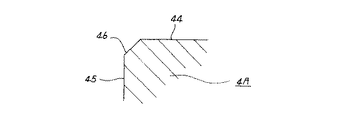
上述の様に構成するトロイダル型無段変速機に於いて、上記入力側、出力側両ディスク2A、4Aの表面には、浸炭処理、浸炭窒化処理、高周波焼き入れ等の熱処理による硬化層を形成している。又、これら入力側、出力側両ディスク2A、4Aの内周面44、44と、これら各ディスク2A、4Aの内側面2a、4aよりも内径側に存在する内端面45、45との連続部には、図2に示す様な面取り部46を形成している。そして、この面取り部46の表面粗さを6.3s以下にして、上記連続部の耐力を向上させている。
【0022】
更に、上記入力側、出力側両ディスク2A、4Aの表面のうち、図1に斜格子で示す部分、即ち、これら各ディスク2A、4Aの外側面2b、4bと、上記内端面45、45と面取り部46と内周面44、44の内端寄り部分とに、ショット・ピーニングを施している。そして、この様にショット・ピーニングを施した、上記両ディスク2A、4Aの外側面2b、4bと内端面45、45と面取り部46、46と内周面44、44の内端寄り部分とに、このショット・ピーニングに基づく圧縮残留応力を存在させている。
【0023】
上述の様に、入力側、出力側両ディスク2A、4Aの外側面2b、4bと、内周面44と、内端面45と、これら両面44、45の連続部である面取り部46とに圧縮残留応力を存在させると、トロイダル型無段変速機の運転時に、上記入力側、出力側両ディスク2A、4Aに曲げ応力が加わっても、これら各ディスク2A、4Aに亀裂等の損傷が発生する事はない。即ち、トロイダル型無段変速機の運転時に上記各ディスク2A、4Aには、前述の図7のB、C、D点に大きな引っ張り応力が加わる。これに対して、上述の様に上記B、D点を含む部分に圧縮残留応力を存在させれば、この圧縮残留応力が上記引っ張り応力を相殺して、上記亀裂等の損傷を発生しにくくできる。尚、ショット・ピーニングにより上記各部分に残留させる圧縮応力は、好ましくは50〜90kgf/mm2 程度にする。
【0024】
尚、トロイダル型無段変速機の運転時に上記入力側、出力側両ディスク2A、4Aには、上記B、D点だけでなく、これら各ディスク2A、4Aの内側面2a、4a上の点であるC点にも、引っ張り応力が加わる。但し、このC点を含むこれら各内側面2a、4aは、図示しないパワーローラの周面と当接する事により動力を伝達するトラクション面であり、例えば表面粗さを、超仕上により0.05Ra以下の平滑面にする必要がある。従って、上記C点を含む内側面2a、4aにショット・ピーニングを施す事はできない。但し、これら各内側面2a、4aは、それぞれ上記平滑面とする為の超仕上等の研削に基づき、硬化層を形成する過程で生じた熱処理異常層を除去しているので、上記C点に加わる大きな引っ張り応力に拘らず、このC点から亀裂等の損傷が発生しにくい。言い換えれば、上記各内側面2a、4aは、引っ張り応力に対して大きな耐力を有する。
【0025】
又、上記入力側、出力側両ディスク2A、4Aの表面のうち、前記各外側面2b、4bと、前記各内端面45、45との表面部分に、前記熱処理に基づいて硬化層を形成した後に削り加工を施して、上記硬化層のうちの熱処理異常層を除去している(請求項1〜3に係る発明)。この様に、トロイダル型無段変速機の運転時に大きな引っ張り応力が加わるB、D点を含む、上記各外側面2b、4bと、前記各内端面45、45とに存在する熱処理異常層を除去する事により、トロイダル型無段変速機の運転時に上記入力側、出力側両ディスク2A、4Aに大きな曲げ応力が加わった場合でも、これら両ディスク2A、4Aに亀裂等の損傷を発生する事を抑えられる。即ち、これら両ディスク2A、4Aに曲げ応力が加わると、上記各点B、D部分に大きな応力が集中する。一方、上記両ディスク2A、4Aの表面を硬化させる為、高周波焼き入れ、浸炭焼き入れ等の熱処理を施すと、これら両ディスク2A、4Aの表面部分に、熱処理異常層が存在する事になる。この様な熱処理異常層が存在すると、上記曲げ応力に伴う応力集中により、上記B、D点から亀裂等の損傷が発生し、上記入力側、出力側両ディスク2A、4Aが破断等の損傷を受ける。これに対して、上述の様に上記両ディスク2A、4Aに熱処理を施した後、上記硬化層部分に存在する上記熱処理異常層を除去すれば、上述の様な原因で上記両ディスク2A、4Aが破断等の損傷を受ける事を防止できる。尚、この様な熱処理異常層の除去と、前述の残留圧縮応力付与とは、単独でも効果を得られるが、組み合わせて行なえば、より優れた効果を得られる。
【0026】
更に、上記入力側、出力側両ディスク2A、4Aの内側面2a、4aの、これら各ディスク2A、4Aの回転中心に対する振れ回り量を0.02mm以下としている。即ち、上記入力側、出力側両ディスク2A、4Aは、前記伝達軸42を中心として回転するが、この回転中心と上記内側面2a、4aの一部でパワーローラの周面と当接する部分との距離が変化すると、これら各部分が、上記各ディスク2A、4Aの回転に伴って振れ回る事になる。この様な振れ回りが生じると、前述の様に、上記パワーローラの周面と上記各内側面2a、4aとの当接状態が不安定になって、トロイダル型無段変速機の運転時に振動が発生したり、上記各パワーローラの変速状態を同調させられなくなったりする。そして、これら振動や変速状態の非同調に基づき、上記各周面と当接する上記各内側面2a、4aに無理な力が加わり、これら各内側面2a、4aに早期剥離が生じる等、やはり上記入力側、出力側両ディスク2A、4Aの耐久性が損なわれてしまう。
【0027】
これに対して、上記入力側、出力側両ディスク2A、4Aの内側面2a、4aの、これら各ディスク2A、4Aの回転中心に対する振れ回り量を0.02mm以下に規制すれば、上述の様な入力側、出力側両ディスク2A、4Aの耐久性低下に結び付く様な振れ回りを防止できる。尚、上記入力側、出力側両ディスク2A、4Aの内側面2a、4aを研削加工する作業は、これら各内側面2a、4aの曲率半径Rの加工公差をプラス側にして行なう。従って、上記研削作業は、この曲率半径Rを公差側に追い込む方向で行なうので、加工作業は比較的容易である。又、曲率半径Rが公差側にずれて大きくなる事は、上記各内側面2a、4aとパワーローラの周面との当接部である、トラクション面の面圧低下につながり、上記入力側、出力側両ディスク2A、4A及びパワーローラの耐久性向上に結び付く為、好ましい。
尚、次の表1は、上記振れ回り量の大きさが、トロイダル型無段変速機の運転に及ぼす影響を知る為、本発明者が行なった実験の結果を示している。
【0028】
【表1】

Figure 0003783374
【0029】
この表1の記載から明らかな通り、上記振れ回り量を0.02mm以下に抑えれば、トロイダル型無段変速機の運転に及ぼす悪影響を、実用上問題ない程度に抑える事ができる。尚、この様に上記両ディスク2A、4Aの振れ回り量を規制する事も、単独で実施して効果を得られるだけでなく、本発明と組み合わせて実施すれば、より優れた効果を得られる。
【0030】
【発明の効果】
本発明のトロイダル型無段変速機は、以上に述べた通り構成され作用するので、入力側、出力側両ディスクの耐久性を向上させて、これら両ディスクを組み込んだトロイダル型無段変速機の耐久性向上を図れる。
【図面の簡単な説明】
【図1】本発明のトロイダル型無段変速機の要部断面図。
【図2】図1のA部拡大図。
【図3】トロイダル型無段変速機の基本構成を、最大減速時の状態で示す略側面図。
【図4】同じく最大増速時の状態で示す略側面図。
【図5】従来から知られている具体的構造の1例を示す要部断面図。
【図6】図5のB−B断面図。
【図7】ディスクに引っ張り応力が加わる部位を説明する為の部分断面図。
【符号の説明】
1、1a 入力軸
2、2A 入力側ディスク
2a 内側面
2b 外側面
3 出力軸
4、4A 出力側ディスク
4a 内側面
4b 外側面
5 枢軸
6 トラニオン
7 変位軸
8 パワーローラ
8a 周面
9 押圧装置
10 カム板
11 保持器
12 ローラ
13、14 カム面
15 入力軸
16、16a ニードル軸受
17 鍔部
18 出力歯車
19 キー
20 支持ポスト
21 円孔
22 ケーシング
23 シリンダケース
24a、24b 支持ピン
25 支持孔
26 外輪
27 ラジアルニードル軸受
28 支持軸部
29 枢支軸部
30 ラジアルニードル軸受
31 ラジアルニードル軸受
32 スラスト玉軸受
33 外輪
34 スラストニードル軸受
35 駆動ロッド
36 駆動ピストン
37 駆動シリンダ
38 支持壁
39 転がり軸受
40 円孔
41 ボールスプライン
42 伝達軸
43 スリーブ
44 内周面
45 内端面
46 面取り部[0001]
BACKGROUND OF THE INVENTION
The toroidal type continuously variable transmission according to the present invention is used as an automatic transmission for automobiles, for example. In particular, the present invention aims to improve the durability of both the input side and output side disks constituting such a toroidal type continuously variable transmission.
[0002]
[Prior art]
The use of a toroidal continuously variable transmission as schematically shown in FIGS. This toroidal type continuously variable transmission supports an input disk 2 concentrically with an input shaft 1 and is arranged concentrically with the input shaft 1 as disclosed in, for example, Japanese Utility Model Publication No. 62-71465. An output side disk 4 is fixed to the end of the output shaft 3. A plurality of (usually 2 to 3) trunnions 6 and 6 that swing around pivots 5 and 5 are provided inside the casing containing the toroidal-type continuously variable transmission. Each of the pivots 5 and 5 has an intermediate portion between the two disks 2 and 4 in the axial direction of the input and output disks 2 and 4 (left and right direction in FIGS. 3 to 4). The disk 4 is arranged in a direction perpendicular to the axial direction of the disk 4 and twisted with respect to the central axes of the disks 2 and 4.
That is, the trunnions 6 and 6 are provided with the pivots 5 and 5 concentrically with each other on the outer side surfaces of both ends. In addition, the intermediate portions of the trunnions 6 and 6 support the base end portions of the displacement shafts 7 and 7, and the trunnions 6 and 6 are swung around the pivot shafts 5 and 5. The inclination angle of the displacement shafts 7 and 7 can be adjusted freely. Power rollers 8 and 8 are rotatably supported around the displacement shafts 7 and 7 supported by the trunnions 6 and 6, respectively. The power rollers 8 and 8 are sandwiched between the input side and output side disks 2 and 4. The inner side surfaces 2a and 4a of the input side and output side discs 2 and 4 facing each other have cross-sections each having an arc centering on a point on the pivot 5 and centering on the input shaft 1 and the output shaft 3. Concave surface obtained when rotated. And the peripheral surfaces 8a and 8a of each power roller 8 and 8 formed in the spherical convex surface are made to contact | abut to the said inner surface 2a and 4a.
[0004]
A loading cam type pressing device 9 is provided between the input shaft 1 and the input side disc 2, and the pressing device 9 makes the input side disc 2 toward the output side disc 4 elastically pressable. Yes. The pressing device 9 includes a cam plate 10 that rotates together with the input shaft 1 and a plurality of (for example, four) rollers 12 and 12 held by a cage 11. On one side surface (left side surface in FIGS. 3 to 4) of the cam plate 10, a cam surface 13 that is an uneven surface extending in the circumferential direction is formed, and the outer side surface of the input side disk 2 (right side in FIGS. 3 to 4). The same cam surface 14 is also formed on the surface). The plurality of rollers 12 and 12 are supported so as to be rotatable about a radial axis with respect to the center of the input shaft 1.
[0005]
When the toroidal type continuously variable transmission configured as described above is used, when the cam plate 10 rotates as the input shaft 1 rotates, the cam surface 13 causes the plurality of rollers 12 and 12 to move outside the input side disk 2. Press against the side cam surface 14. As a result, the input side disk 2 is pressed against the power rollers 8 and 8 and at the same time, based on the pressing between the pair of cam surfaces 13 and 14 and the plurality of rollers 12 and 12, The input side disk 2 rotates. Then, the rotation of the input side disk 2 is transmitted to the output side disk 4 through the power rollers 8 and 8, and the output shaft 3 fixed to the output side disk 4 is rotated.
[0006]
When the rotational speed ratio (transmission ratio) between the input shaft 1 and the output shaft 3 is changed, and when first decelerating between the input shaft 1 and the output shaft 3, each trunnion 6 is centered on the pivot shafts 5 and 5. 6, and the peripheral surfaces 8 a, 8 a of the power rollers 8, 8 are located near the center of the inner surface 2 a of the input side disk 2 and the outer periphery of the inner surface 4 a of the output side disk 4 as shown in FIG. 3. The displacement shafts 7 and 7 are inclined so as to abut against the offset portions. On the other hand, when increasing the speed, the trunnions 6 and 6 are swung around the pivot shafts 5 and 5 so that the peripheral surfaces 8a and 8a of the power rollers 8 and 8 are as shown in FIG. The displacement shafts 7 and 7 are inclined so as to abut the outer peripheral portion of the inner side surface 2a of the input side disc 2 and the central portion of the inner side surface 4a of the output side disc 4 respectively. If the inclination angle of each of the displacement shafts 7 and 7 is set intermediate between those shown in FIGS. 3 and 4, an intermediate transmission ratio can be obtained between the input shaft 1 and the output shaft 3.
[0007]
5 to 6 show a more specific toroidal type continuously variable transmission described in the microfilm of Japanese Utility Model Application No. 63-69293 (Japanese Utility Model Laid-Open No. 1-173552). The input side disk 2 and the output side disk 4 are rotatably supported around the input shaft 15 via needle bearings 16 and 16, respectively. The cam plate 10 is spline-engaged with the outer peripheral surface of the end portion (left end portion in FIG. 5) of the input shaft 15, and the flange portion 17 prevents movement in the direction away from the input side disk 2. Then, a loading cam type pressing device 9 that rotates the input side disk 2 while pressing the input side disk 2 toward the output side disk 4 based on the rotation of the input shaft 15 by the cam plate 10 and the rollers 12 and 12. It is composed. An output gear 18 is coupled to the output side disk 4 by means of keys 19, 19, so that the output side disk 4 and the output gear 18 rotate in synchronization. The output gear 18 and a gear (not shown) meshed with the output gear 18 constitute power extraction means for extracting the rotation of the output side disk 4.
[0008]
The pivots 5, 5 provided at both ends of the pair of trunnions 6, 6 are swingable and displaceable in a pair of support posts 20, 20 in the axial direction (front and back direction in FIG. 5, left and right direction in FIG. 6). I support it. The pair of support posts 20, 20 is a metal plate having sufficient rigidity, and a circular hole 21 formed in the center is fixed to the inner surface of the casing 22 or the side surface of the cylinder case 23 provided in the casing 22. By being externally fitted to the provided support pins 24a and 24b, it is supported inside the casing 22 so as to be swingable and displaceable in the axial direction of the pivots 5 and 5. In addition, circular support holes 25 and 25 are formed at both ends of the support posts 20 and 20, respectively. The pivots 5 and 5 are respectively connected to the support holes 25 and 25, respectively. It is supported by radial needle bearings 27, 27 having 26, 26. Based on these configurations, the trunnions 6 and 6 are supported in the casing 22 such that the trunnions 6 and 6 are freely swingable around the pivots 5 and 5 and displaced in the axial direction of the pivots 5 and 5. ing.
[0009]
The displacement shafts 7 and 7 are supported in the circular holes 40 and 40 formed in the intermediate part of the trunnions 6 and 6 supported in the casing 22 as described above. Each of these displacement shafts 7 and 7 has support shaft portions 28 and 28 and pivot shaft portions 29 and 29 that are parallel to each other and eccentric, respectively. Of these, the support shaft portions 28 and 28 are supported inside the circular holes 40 and 40 so as to be swingable via radial needle bearings 30 and 30. Further, power rollers 8 and 8 are rotatably supported around the pivot shaft portions 29 and 29 via radial needle bearings 31 and 31, respectively.
[0010]
The pair of displacement shafts 7 and 7 are provided at 180 ° opposite positions with the input shaft 15 as the center. The direction in which the pivot shafts 29 and 29 of the displacement shafts 7 and 7 are eccentric with respect to the support shafts 28 and 28 is the same with respect to the rotation direction of the input side and output side disks 2 and 4. It is set as a direction (left-right reverse direction in FIG. 6). Further, the eccentric direction is a direction substantially orthogonal to the direction in which the input shaft 15 is disposed (the left-right direction in FIG. 5 and the front-back direction in FIG. 6). Accordingly, the power rollers 8 and 8 are supported so as to be slightly displaceable in the direction in which the input shaft 15 is disposed. As a result, due to variations in dimensional accuracy of the constituent parts or elastic deformation at the time of power transmission, the power rollers 8 and 8 are moved in the axial direction of the input shaft 15 (left and right direction in FIG. 5, FIG. 6). Even when it tends to be displaced in the direction of the front and back), this displacement can be absorbed without applying excessive force to each component.
[0011]
Further, between the outer surface of each of the power rollers 8 and 8 and the inner surface of the intermediate portion of each of the trunnions 6 and 6, thrust ball bearings 32 and 32, etc. in order from the outer surface side of the power rollers 8 and 8. A thrust rolling bearing and thrust bearings such as thrust needle bearings 34 and 34 for supporting a thrust load applied to the outer rings 33 and 33 described below are provided. Of these, the thrust ball bearings 32 and 32 correspond to the thrust rolling bearing described in claim 1, and support the load in the thrust direction applied to each of the power rollers 8 and 8, while supporting each of the power rollers 8 and 8. Allow 8 rotations. The thrust needle roller bearings 34, 34 support the thrust load applied to the outer rings 33, 33 of the thrust ball bearings 32, 32 from the power rollers 8, 8, while supporting the pivot shafts 29, 29. The outer rings 33 and 33 are allowed to swing around the support shafts 28 and 28.
[0012]
Further, driving rods 35 and 35 are coupled to one end portions (the left end portion in FIG. 6) of the trunnions 6 and 6, respectively, and driving pistons 36 and 36 are provided on the outer peripheral surfaces of the intermediate portions of the driving rods 35 and 35, respectively. It is fixed. The drive pistons 36 and 36 are oil-tightly fitted in drive cylinders 37 and 37 provided in the cylinder case 23, respectively. Further, a pair of rolling bearings 39, 39 are provided between the support wall 38 provided in the casing 22 and the input shaft 15, and the input shaft 15 is rotatably supported in the casing 22. Yes.
[0013]
In the case of the toroidal type continuously variable transmission configured as described above, the rotation of the input shaft 15 is transmitted to the input side disk 2 via the pressing device 9. Then, the rotation of the input side disk 2 is transmitted to the output side disk 4 via a pair of power rollers 8 and 8, and the rotation of the output side disk 4 is further taken out from the output gear 18. When changing the rotational speed ratio between the input shaft 15 and the output gear 18, the pair of drive pistons 36, 36 are displaced in opposite directions. As the drive pistons 36 and 36 are displaced, the pair of trunnions 6 and 6 are displaced in the opposite directions. For example, the lower power roller 8 in FIG. The power rollers 8 are displaced to the left in the figure. As a result, the direction of the tangential force acting on the contact portion between the peripheral surfaces 8a, 8a of the power rollers 8, 8 and the inner side surfaces 2a, 4a of the input side disk 2 and the output side disk 4 changes. To do. As the force changes, the trunnions 6 and 6 swing in directions opposite to each other in FIG. 5 about the pivots 5 and 5 pivotally supported by the support posts 20 and 20. As a result, as shown in FIGS. 3 to 4 described above, the contact position between the peripheral surfaces 8a and 8a of the power rollers 8 and 8 and the inner surfaces 2a and 4a changes, and the input shaft 15 and The rotational speed ratio with the output gear 18 changes.
[0014]
When the power rollers 8 and 8 are displaced in the axial direction of the input shaft 15 as a result of elastic deformation of the constituent parts during power transmission, the displacement shafts pivotally supporting the power rollers 8 and 8 are used. 7 and 7 slightly swing around the support shafts 28 and 28. As a result of this swinging, the outer side surfaces of the outer rings 33, 33 of the thrust ball bearings 32, 32 and the inner side surfaces of the trunnions 6, 6 are relatively displaced. Since the thrust needle bearings 34, 34 exist between the outer surface and the inner surface, the force required for this relative displacement is small. Therefore, as described above, the force for changing the inclination angle of each displacement shaft 7, 7 can be small.
[0015]
[Problems to be solved by the invention]
During operation of the toroidal type continuously variable transmission configured and operated as described above, both the input side and output side disks 2 and 4 are repeatedly subjected to complicated and large forces based on the pressing with the power rollers 8 and 8. . For example, during operation of the toroidal-type continuously variable transmission, a thrust load F is applied to the inner surface 4a of the output side disk 4 from the power roller 8 to the point A in FIG. The output side disk 4 is elastically deformed based on such a thrust load, and as a result, a large tensile stress is concentrated on the B, C, and D portions of FIG. These parts to which tensile stress is applied move in the circumferential direction based on the rotation of the output side disk 4 accompanying the operation of the toroidal type continuously variable transmission. Therefore, when attention is paid to a certain part in the circumferential direction, a large tensile stress is repeatedly applied to the part. Such repeated application of tensile stress is almost the same for the input side disk 2.
The tensile stress repeatedly applied to both the input side and output side disks 2 and 4 in this way causes damage such as cracks in both the input side and output side disks 2 and 4, and the both disks 2 and 4 are destroyed. Cause. Therefore, in order to sufficiently ensure the durability of the toroidal type continuously variable transmission, the input side and output side disks 2 and 4 are damaged such as cracks regardless of the tensile stress as described above. Consideration to prevent this is necessary.
[0016]
Further, the inner side surfaces 2a and 4a of the input side and output side discs 2 and 4 which are the surfaces in contact with the peripheral surfaces 8a and 8a of the power rollers 8 and 8 are used for the rotation of the discs 2 and 4, respectively. When it is swung around, the contact state between the peripheral surfaces 8a and 8a and the inner surfaces 2a and 4a becomes unstable. As a result, vibration occurs during the operation of the toroidal type continuously variable transmission, the shifting states of the power rollers 8 and 8 cannot be synchronized, or hunting occurs. Then, based on these vibration and shift state non-synchronization, or hunting, an unreasonable force is applied to each of the inner side surfaces 2a, 4a contacting the respective peripheral surfaces 8a, 8a. The durability of both the input side and output side disks 2 and 4 is also impaired, such as peeling.
The toroidal continuously variable transmission of the present invention has been invented in view of such circumstances.
[0017]
[Means for Solving the Problems]
The toroidal type continuously variable transmission of the present invention includes an input shaft that is rotatably supported, and an input side disk that is rotatable together with the input shaft, in the same manner as the previously known toroidal type continuously variable transmission. The output side disk disposed concentrically with the input side disk and rotatably supported with respect to the input side disk, and both of the input side and the output side disks in the intermediate direction between both the input side and the output side disks. A plurality of trunnions arranged at right angles to the axial direction of the disks and twisted with respect to the central axes of both disks, and supported by the displacement shafts supported by the respective trunnions. A plurality of power rollers sandwiched between both the input side and output side disks, and provided between the outer surface of each of the power rollers and the inner surface of each of the trunnions. It consists of a thrust rolling bearing. Then, the inner side surfaces of the input side and output side discs facing each other are concave surfaces each having a circular cross section, and the peripheral surfaces of the power rollers are spherical convex surfaces. It is in contact.
[0018]
In particular, in the toroidal-type continuously variable transmission of the present invention, the continuous portion of the inner peripheral surface of both the input side and output side discs and the inner end surface that exists on the inner diameter side of the inner side surfaces of these two discs. chamfer, the input side and the output side surface to a heat treatment hardened layer of both disks are formed respectively, of these two disc surface, present on the inner diameter side of the inner surface is concave in the arcuate the surface portion of the inner end face, subjected to cutting processing after forming the hardened layer, is characterized in that is removed to a heat treatment abnormality layer of the hardened layer. In this case, preferably , as described in claim 2, the chamfered portion has a surface roughness of 6.3 s or less to improve the yield strength of the continuous portion where the chamfered portion is formed. Alternatively, as described in claim 3 , in addition to the inner end face, the hardened layer is formed by forming the hardened layer on both the outer side surface portions of the input side and output side discs and then cutting the hardened layer. The heat treatment abnormal layer is removed.
[0019]
[Action]
The operation when the toroidal type continuously variable transmission of the present invention configured as described above transmits rotational force between the input side disk and the output side disk, and the speed change between these input side disk and output side disk. The effect of changing the ratio is the same as that of the conventional structure described above.
In particular, in the case of the toroidal type continuously variable transmission according to the present invention, it is possible to improve the durability of both the input side and output side disks .
[0020]
DETAILED DESCRIPTION OF THE INVENTION
FIGS. 1 and 2 show opposing portions of both the input side and output side disks 2A and 4A, which are the main parts of the toroidal type continuously variable transmission of the present invention. FIG. 1 shows one half of a so-called double-cavity toroidal continuously variable transmission in which two pairs of input and output disks 2A and 4A are provided in parallel with each other in the direction of power transmission. . The rotation of the input shaft 1a is transmitted to the input side disk 2A via a loading cam type pressing device 9. Further, the rotation of the input side disk 2A is transmitted to a transmission shaft 42 connected at one end thereof via a ball spline 41 provided on the inner peripheral edge of the input side disk 2A. The other input side disk not shown is rotated in synchronization with the input side disk 2A. Further, the rotation of the input side disk 2A is carried out via a pair of power rollers 8 (FIGS. 3 to 6) (not shown) provided on both sides in the front and back direction of FIG. 4A is transmitted. The output side disk 4A is spline engaged with both ends of a sleeve 43 provided around the intermediate part of the transmission shaft 42 together with another output side disk (not shown). A radial needle bearing 16a is provided between the inner peripheral surface of the output side disk 4A (the inner side surface 4a side half, the left half portion of FIG. 1) and the intermediate outer peripheral surface of the transmission shaft 42. Thus, the output side disk 4A and the transmission shaft 42 can be freely rotated relative to each other. An output gear (not shown) is provided on the outer peripheral surface of the intermediate portion of the sleeve 43 between the output side disk 4A and another output side disk so that the pair of input side disks 2A can The power transmitted to the pair of output side disks 4A can be taken out freely.
[0021]
In the toroidal-type continuously variable transmission configured as described above, a hardened layer is formed on the surfaces of both the input side and output side disks 2A and 4A by heat treatment such as carburizing, carbonitriding, and induction hardening. is doing. Further, a continuous portion of the inner peripheral surfaces 44, 44 of both the input side and output side discs 2A, 4A and the inner end surfaces 45, 45 existing on the inner diameter side of the inner side surfaces 2a, 4a of these discs 2A, 4A. A chamfered portion 46 as shown in FIG. 2 is formed. And the surface roughness of this chamfer 46 is made 6.3 s or less, and the proof stress of the said continuous part is improved.
[0022]
Further, of the surfaces of both the input side and output side disks 2A and 4A, the portion shown by the oblique grid in FIG. 1, that is, the outer surfaces 2b and 4b of the disks 2A and 4A, and the inner end surfaces 45 and 45, Shot peening is applied to the chamfered portion 46 and the inner peripheral portions 44 and 44 near the inner ends. Then, the outer surfaces 2b and 4b of both the disks 2A and 4A, the inner end surfaces 45 and 45, the chamfered portions 46 and 46, and the inner peripheral surfaces 44 and 44 near the inner ends are subjected to shot peening in this way. , A compression residual stress based on this shot peening is present.
[0023]
As described above, compression is performed on the outer side surfaces 2b and 4b of both the input side and output side discs 2A and 4A, the inner peripheral surface 44, the inner end surface 45, and the chamfered portion 46 which is a continuous portion of the both surfaces 44 and 45. When residual stress is present, even if bending stress is applied to both the input side and output side disks 2A and 4A during operation of the toroidal type continuously variable transmission, damage such as cracks occurs in these disks 2A and 4A. There is nothing. That is, during operation of the toroidal-type continuously variable transmission, a large tensile stress is applied to each of the disks 2A, 4A at points B, C, D in FIG. On the other hand, if a compressive residual stress is present in the portion including the points B and D as described above, the compressive residual stress cancels the tensile stress and can hardly cause damage such as cracks. . The compressive stress that remains in each of the above portions by shot peening is preferably about 50 to 90 kgf / mm 2 .
[0024]
When the toroidal continuously variable transmission is operated, both the input side and output side disks 2A and 4A are not limited to the above points B and D, but also on the inner side surfaces 2a and 4a of the disks 2A and 4A. A tensile stress is also applied to a certain point C. However, each of these inner side surfaces 2a and 4a including the point C is a traction surface that transmits power by contacting a peripheral surface of a power roller (not shown). For example, the surface roughness is 0.05Ra or less by super finishing. It is necessary to have a smooth surface. Therefore, shot peening cannot be applied to the inner side surfaces 2a and 4a including the point C. However, each of these inner side surfaces 2a, 4a is based on grinding such as super-finishing to make the smooth surface, respectively, and removes the heat treatment abnormal layer generated in the process of forming the hardened layer. Regardless of the large tensile stress applied, damage such as cracks hardly occurs from this point C. In other words, each of the inner side surfaces 2a and 4a has a large proof strength against tensile stress.
[0025]
Further, a hardened layer was formed on the surface portions of the outer side surfaces 2b and 4b and the inner end surfaces 45 and 45 among the surfaces of the input side and output side discs 2A and 4A based on the heat treatment. A machining process is performed later to remove the heat treatment abnormal layer in the hardened layer (invention according to claims 1 to 3 ). In this way, the heat treatment abnormal layers existing on the outer side surfaces 2b and 4b and the inner end surfaces 45 and 45 including the points B and D to which a large tensile stress is applied during operation of the toroidal type continuously variable transmission are removed. As a result, even when a large bending stress is applied to both the input side and output side disks 2A and 4A during the operation of the toroidal type continuously variable transmission, damage to these both disks 2A and 4A may occur. It can be suppressed. That is, when a bending stress is applied to both the disks 2A and 4A, a large stress is concentrated on the points B and D. On the other hand, when a heat treatment such as induction hardening or carburizing quenching is performed to harden the surfaces of both the disks 2A and 4A, a heat treatment abnormal layer exists on the surface portions of both the disks 2A and 4A. If such an abnormal heat treatment layer exists, stress concentration due to the bending stress causes damage such as cracks from the points B and D, and both the input side and output side disks 2A and 4A are damaged such as fracture. receive. On the other hand, if both the disks 2A and 4A are subjected to heat treatment as described above and then the heat treatment abnormal layer existing in the hardened layer portion is removed, the both disks 2A and 4A are caused by the above-described causes. Can be prevented from being damaged such as breaking. It should be noted that the removal of such a heat treatment abnormal layer and the application of the residual compressive stress as described above can be effective alone, but if combined, a more excellent effect can be obtained.
[0026]
Further, the amount of swinging of the inner side surfaces 2a, 4a of both the input side and output side disks 2A, 4A with respect to the rotation center of each of the disks 2A, 4A is set to 0.02 mm or less . That is, both the input side and output side disks 2A and 4A rotate around the transmission shaft 42, and the center of rotation and a part of the inner side surfaces 2a and 4a which are in contact with the peripheral surface of the power roller. When these distances change, each of these parts swings around as the disks 2A and 4A rotate. When such a whirling occurs, the contact state between the peripheral surface of the power roller and the inner side surfaces 2a and 4a becomes unstable as described above, and vibration occurs during operation of the toroidal continuously variable transmission. May occur or the shifting state of each of the power rollers cannot be synchronized. Then, based on these vibrations and shift state non-synchronization, an excessive force is applied to each of the inner side surfaces 2a, 4a that comes into contact with the respective peripheral surfaces, and early peeling occurs on each of the inner side surfaces 2a, 4a. The durability of both the input side and output side disks 2A, 4A is impaired.
[0027]
On the other hand, if the swinging amount of the inner side surfaces 2a, 4a of the input side and output side discs 2A, 4A with respect to the rotation center of the discs 2A, 4A is restricted to 0.02 mm or less, as described above. Thus, it is possible to prevent such a swinging that leads to a decrease in durability of both the input side and output side disks 2A, 4A. The work of grinding the inner side surfaces 2a and 4a of both the input side and output side discs 2A and 4A is performed with the processing tolerance of the curvature radius R of each of the inner side surfaces 2a and 4a being set to the plus side. Therefore, the grinding operation is performed in such a direction that the radius of curvature R is driven toward the tolerance side, and therefore the machining operation is relatively easy. Further, the deviation of the radius of curvature R toward the tolerance side increases, leading to a reduction in the surface pressure of the traction surface, which is a contact portion between the inner side surfaces 2a, 4a and the peripheral surface of the power roller, and the input side, This is preferable because it leads to improved durability of the output side disks 2A and 4A and the power roller.
Table 1 below shows the results of an experiment conducted by the present inventor in order to know the influence of the swing amount on the operation of the toroidal continuously variable transmission.
[0028]
[Table 1]
Figure 0003783374
[0029]
As is apparent from the description in Table 1, if the swing amount is suppressed to 0.02 mm or less, the adverse effect on the operation of the toroidal type continuously variable transmission can be suppressed to a level where there is no practical problem. In addition, regulating the swing amount of the two disks 2A and 4A in this way is not only effective when performed alone, but also when combined with the present invention , more excellent effects can be obtained. .
[0030]
【The invention's effect】
Since the toroidal continuously variable transmission of the present invention is configured and operates as described above, the durability of both the input side and output side disks is improved, and the toroidal type continuously variable transmission incorporating these both disks is used. Durability can be improved.
[Brief description of the drawings]
FIG. 1 is a cross-sectional view of a main part of a toroidal continuously variable transmission according to the present invention.
FIG. 2 is an enlarged view of a portion A in FIG.
FIG. 3 is a schematic side view showing a basic configuration of a toroidal-type continuously variable transmission in a state of maximum deceleration.
FIG. 4 is a schematic side view showing the state of the maximum speed increase.
FIG. 5 is a cross-sectional view of an essential part showing an example of a specific structure conventionally known.
6 is a cross-sectional view taken along the line BB in FIG.
FIG. 7 is a partial cross-sectional view for explaining a portion where tensile stress is applied to the disk.
[Explanation of symbols]
DESCRIPTION OF SYMBOLS 1, 1a Input shaft 2, 2A Input side disk 2a Inner side surface 2b Outer side surface 3 Output shaft 4, 4A Output side disk 4a Inner side surface 4b Outer side surface 5 Pivot 6 Trunnion 7 Displacement shaft 8 Power roller 8a Circumferential surface 9 Pressing device 10 Cam Plate 11 Cage 12 Rollers 13 and 14 Cam surface 15 Input shaft 16 and 16a Needle bearing 17 flange 18 Output gear 19 Key 20 Support post 21 Circular hole 22 Casing 23 Cylinder case 24a and 24b Support pin 25 Support hole 26 Outer ring 27 Radial Needle bearing 28 Support shaft portion 29 Pivoting shaft portion 30 Radial needle bearing 31 Radial needle bearing 32 Thrust ball bearing 33 Outer ring 34 Thrust needle bearing 35 Drive rod 36 Drive piston 37 Drive cylinder 38 Support wall 39 Rolling bearing 40 Circular hole 41 Ball spline 42 Transmission shaft 43 Sleeve 4 The inner peripheral surface 45 inner end face 46 chamfered portion

Claims (3)

回転自在に支持された入力軸と、この入力軸と共に回転自在な入力側ディスクと、この入力側ディスクと同心に配置され、且つこの入力側ディスクに対する回転自在に支持された出力側ディスクと、これら入力側、出力側両ディスクの軸方向に関してこれら両ディスクの中間部に、これら両ディスクの軸方向に対し直角方向で且つこれら両ディスクの中心軸に対し捻れの位置に配置されて当該位置で揺動する複数のトラニオンと、これら各トラニオンに支持された変位軸に回転自在に支持され、入力側、出力側両ディスクの間に挟持された複数個のパワーローラと、これら各パワーローラの外側面と上記各トラニオンの内側面との間に設けたスラスト転がり軸受とから構成し、入力側、出力側両ディスクの互いに対向する内側面を、それぞれ断面が円弧形の凹面とし、上記各パワーローラの周面を球面状の凸面として、この周面と上記内側面とを当接させたトロイダル型無段変速機に於いて、上記入力側、出力側両ディスクの内周面と、これら両ディスクの内側面よりも内径側に存在する内端面との連続部に面取り部が、上記入力側、出力側両ディスクの表面に熱処理硬化層が、それぞれ形成されており、これら両ディスクの表面のうち、上記円弧形の凹面である内側面よりも内径側に存在する上記内端面の表面部分に、上記硬化層を形成した後に削り加工を施して、この硬化層のうちの熱処理異常層を除去している事を特徴とするトロイダル型無段変速機。An input shaft that is rotatably supported, an input side disk that is rotatable together with the input shaft, an output side disk that is disposed concentrically with the input side disk and is rotatably supported with respect to the input side disk, and In the axial direction of both the input and output discs, they are arranged in the middle of these discs at a position perpendicular to the axial directions of these discs and twisted with respect to the central axes of these discs. A plurality of moving trunnions, a plurality of power rollers rotatably supported by a displacement shaft supported by each trunnion, and sandwiched between both input side and output side disks, and outer surfaces of these power rollers And a thrust rolling bearing provided between the inner surface of each trunnion, and the inner surfaces facing each other of both the input side and output side disks are respectively Surface is a concave arcuate, as a spherical convex surface of the peripheral surface of the power rollers, In this peripheral surface and the toroidal type continuously variable transmission is brought into contact and the inner side, the input side, The chamfered portion is a continuous portion between the inner peripheral surface of both the output side discs and the inner end surface existing on the inner diameter side of the inner side surfaces of these discs, and the heat treatment hardened layer is on the surfaces of the input side and output side discs . are formed respectively, subjected of these two disk surface, the surface portion of the inner end surface present on the inner diameter side of the inner surface is concave in the arcuate, the cutting process after forming the hardened layer A toroidal-type continuously variable transmission characterized by removing the heat treatment abnormal layer of the hardened layer. 面取り部の表面粗さを6.3s以下にして、この面取り部を形成した連続部の耐力を向上させている、請求項1に記載したトロイダル型無段変速機。 The toroidal continuously variable transmission according to claim 1, wherein the chamfered portion has a surface roughness of 6.3 s or less to improve the proof stress of the continuous portion formed with the chamfered portion . 内端面に加えて、入力側、出力側両ディスクの外側面の表面部分にも、硬化層を形成した後に削り加工を施して、この硬化層のうちの熱処理異常層を除去している、請求項1〜2のうちの何れか1項に記載したトロイダル型無段変速機。In addition to the inner end face, the input side, on the surface portion of the outer surface of the output side disks, is subjected to machining cutting after forming the hardened layer, and removing the heat-treated abnormal layers of the cured layer, wherein Item 3. The toroidal continuously variable transmission according to any one of Items 1 to 2 .
JP31346597A 1997-11-12 1997-11-14 Toroidal continuously variable transmission Expired - Fee Related JP3783374B2 (en)

Priority Applications (5)

Application Number Priority Date Filing Date Title
JP31346597A JP3783374B2 (en) 1997-11-14 1997-11-14 Toroidal continuously variable transmission
US09/188,711 US6074324A (en) 1997-11-12 1998-11-10 Toroidal type continuously variable transmission
DE19861194A DE19861194B4 (en) 1997-11-12 1998-11-12 Infinitely-variable toroidal gear with a precisely known gear ratio
DE19852249A DE19852249C2 (en) 1997-11-12 1998-11-12 Stepless toroidal gear
DE19861271A DE19861271B4 (en) 1997-11-12 1998-11-12 Infinitely-variable toroidal gear with a precisely known gear ratio

Applications Claiming Priority (1)

Application Number Priority Date Filing Date Title
JP31346597A JP3783374B2 (en) 1997-11-14 1997-11-14 Toroidal continuously variable transmission

Publications (2)

Publication Number Publication Date
JPH11148543A JPH11148543A (en) 1999-06-02
JP3783374B2 true JP3783374B2 (en) 2006-06-07

Family

ID=18041639

Family Applications (1)

Application Number Title Priority Date Filing Date
JP31346597A Expired - Fee Related JP3783374B2 (en) 1997-11-12 1997-11-14 Toroidal continuously variable transmission

Country Status (1)

Country Link
JP (1) JP3783374B2 (en)

Families Citing this family (4)

* Cited by examiner, † Cited by third party
Publication number Priority date Publication date Assignee Title
US6261203B1 (en) 1998-12-28 2001-07-17 Nsk Ltd. Toroidal type continuously variable transmission
JP4474945B2 (en) 2004-02-26 2010-06-09 日本精工株式会社 Toroidal continuously variable transmission
JP4164680B2 (en) 2004-03-29 2008-10-15 日本精工株式会社 Toroidal type continuously variable transmission disk processing method
JP2007155070A (en) * 2005-12-07 2007-06-21 Jtekt Corp Troidal type continuously variable transmission

Also Published As

Publication number Publication date
JPH11148543A (en) 1999-06-02

Similar Documents

Publication Publication Date Title
JP3783374B2 (en) Toroidal continuously variable transmission
JP3951401B2 (en) Loading cam for toroidal type continuously variable transmission
US6074324A (en) Toroidal type continuously variable transmission
JP3733713B2 (en) Toroidal continuously variable transmission
US6174257B1 (en) Toroidal type continuously variable transmission
JP3718973B2 (en) Toroidal continuously variable transmission
JP3435781B2 (en) Toroidal type continuously variable transmission
JP4069573B2 (en) Toroidal continuously variable transmission
JP3852188B2 (en) Method for manufacturing intermediate disk for toroidal continuously variable transmission
JP4280978B2 (en) Toroidal continuously variable transmission
JP2002181151A (en) Toroidal-type continuously variable transmission
JP4062950B2 (en) Toroidal continuously variable transmission
JP4003347B2 (en) Toroidal continuously variable transmission
JP2001050360A (en) Toroidal continuously variable transmission
JP4211157B2 (en) Toroidal continuously variable transmission
JP3849332B2 (en) Manufacturing method of disk for toroidal type continuously variable transmission
JP3617258B2 (en) Toroidal continuously variable transmission
JP4174712B2 (en) Induction hardening method for trunnion of toroidal type continuously variable transmission
JP4051791B2 (en) Half toroidal continuously variable transmission
US6374477B1 (en) Method for working input shaft for toroidal-type continuously variable transmission
JP3820978B2 (en) Toroidal continuously variable transmission
JP4089085B2 (en) Toroidal continuously variable transmission
JP4280963B2 (en) Toroidal continuously variable transmission
JP2007240004A (en) Power roller unit for toroidal continuously variable transmission
JP4470539B2 (en) Trunnion manufacturing method

Legal Events

Date Code Title Description
A521 Written amendment

Free format text: JAPANESE INTERMEDIATE CODE: A523

Effective date: 20040930

A621 Written request for application examination

Free format text: JAPANESE INTERMEDIATE CODE: A621

Effective date: 20040930

A977 Report on retrieval

Free format text: JAPANESE INTERMEDIATE CODE: A971007

Effective date: 20050927

A131 Notification of reasons for refusal

Free format text: JAPANESE INTERMEDIATE CODE: A131

Effective date: 20051206

A521 Written amendment

Free format text: JAPANESE INTERMEDIATE CODE: A523

Effective date: 20060201

TRDD Decision of grant or rejection written
A01 Written decision to grant a patent or to grant a registration (utility model)

Free format text: JAPANESE INTERMEDIATE CODE: A01

Effective date: 20060221

A61 First payment of annual fees (during grant procedure)

Free format text: JAPANESE INTERMEDIATE CODE: A61

Effective date: 20060306

R150 Certificate of patent or registration of utility model

Free format text: JAPANESE INTERMEDIATE CODE: R150

FPAY Renewal fee payment (event date is renewal date of database)

Free format text: PAYMENT UNTIL: 20100324

Year of fee payment: 4

FPAY Renewal fee payment (event date is renewal date of database)

Free format text: PAYMENT UNTIL: 20100324

Year of fee payment: 4

FPAY Renewal fee payment (event date is renewal date of database)

Free format text: PAYMENT UNTIL: 20110324

Year of fee payment: 5

FPAY Renewal fee payment (event date is renewal date of database)

Free format text: PAYMENT UNTIL: 20120324

Year of fee payment: 6

FPAY Renewal fee payment (event date is renewal date of database)

Free format text: PAYMENT UNTIL: 20130324

Year of fee payment: 7

FPAY Renewal fee payment (event date is renewal date of database)

Free format text: PAYMENT UNTIL: 20130324

Year of fee payment: 7

FPAY Renewal fee payment (event date is renewal date of database)

Free format text: PAYMENT UNTIL: 20140324

Year of fee payment: 8

LAPS Cancellation because of no payment of annual fees