JP4069573B2 - Toroidal continuously variable transmission - Google Patents

Toroidal continuously variable transmission Download PDF

Info

Publication number
JP4069573B2
JP4069573B2 JP2000122648A JP2000122648A JP4069573B2 JP 4069573 B2 JP4069573 B2 JP 4069573B2 JP 2000122648 A JP2000122648 A JP 2000122648A JP 2000122648 A JP2000122648 A JP 2000122648A JP 4069573 B2 JP4069573 B2 JP 4069573B2
Authority
JP
Japan
Prior art keywords
trunnion
support plate
continuously variable
variable transmission
plate portion
Prior art date
Legal status (The legal status is an assumption and is not a legal conclusion. Google has not performed a legal analysis and makes no representation as to the accuracy of the status listed.)
Expired - Fee Related
Application number
JP2000122648A
Other languages
Japanese (ja)
Other versions
JP2001304366A5 (en
JP2001304366A (en
Inventor
パーチェ アントニオ
山下  智史
伸夫 後藤
Current Assignee (The listed assignees may be inaccurate. Google has not performed a legal analysis and makes no representation or warranty as to the accuracy of the list.)
NSK Ltd
Original Assignee
NSK Ltd
Priority date (The priority date is an assumption and is not a legal conclusion. Google has not performed a legal analysis and makes no representation as to the accuracy of the date listed.)
Filing date
Publication date
Application filed by NSK Ltd filed Critical NSK Ltd
Priority to JP2000122648A priority Critical patent/JP4069573B2/en
Publication of JP2001304366A publication Critical patent/JP2001304366A/en
Publication of JP2001304366A5 publication Critical patent/JP2001304366A5/ja
Application granted granted Critical
Publication of JP4069573B2 publication Critical patent/JP4069573B2/en
Anticipated expiration legal-status Critical
Expired - Fee Related legal-status Critical Current

Links

Images

Description

【0001】
【発明の属する技術分野】
この発明に係るトロイダル型無段変速機は、例えば自動車用の自動変速機の変速ユニットとして、或は各種産業機械用の変速機として、それぞれ利用する。
【0002】
【従来の技術】
自動車用変速機として、図3〜4に略示する様なトロイダル型無段変速機を使用する事が、一部で実施されている。このトロイダル型無段変速機は、例えば実開昭62−71465号公報に開示されている様に、入力軸1と同心に第一のディスクである入力側ディスク2を支持し、この入力軸1と同心に配置された出力軸3の端部に、第二のディスクである出力側ディスク4を固定している。トロイダル型無段変速機を納めたケーシングの内側には、上記入力軸1並びに出力軸3に対し捻れの位置にある枢軸5、5を中心として揺動するトラニオン6、6が設けられている。
【0003】
即ち、上記各トラニオン6は、図5及び後述する図7に示す様に、支持板部7の長さ方向(図5、7の左右方向)両端部に1対の折れ曲がり壁部8、8を、この支持板部7の内側面側(図5の上側)に折れ曲がる状態で形成している。そして、上記各折れ曲がり壁部8、8の外側面(上記支持板部7と反対側の面)に上記各枢軸5、5を、互いに同心に設けている。又、上記支持板部7の中間部には、次述する変位軸9の基半部を支持する為の円孔10を形成している。
【0004】
それぞれがこの様な構成を有する各トラニオン6、6を構成する支持板部7の中間部に形成した上記円孔10には、上記変位軸9の基半部を支持している。そして、上記各枢軸5、5を中心として上記各トラニオン6、6を揺動させる事により、これら各トラニオン6、6の中間部に支持した変位軸9の傾斜角度の調節を自在としている。又、これら各トラニオン6、6にそれぞれの基半部を支持された変位軸9のうちで、これら各トラニオン6、6の内側面から突出した先半部の周囲に、それぞれパワーローラ11を回転自在に支持している。そして、各パワーローラ11、11を、前記入力側、出力側両ディスク2、4の間に挟持している。尚、上記各変位軸9、9の基半部と先半部とは、互いに偏心している。
【0005】
これら入力側、出力側両ディスク2、4の互いに対向する内側面2a、4aは、それぞれ断面が、上記枢軸5を中心とする円弧若しくはこの様な円弧に近い曲線を回転させて得られる凹面をなしている。そして、球状凸面に形成された各パワーローラ11、11の周面11a、11aを、上記各内側面2a、4aに当接させている。
【0006】
前記入力軸1と入力側ディスク2との間には、ローディングカム式の押圧装置12を設け、この押圧装置12によって、上記入力側ディスク2を出力側ディスク4に向け、弾性的に押圧している。上記押圧装置12は、前記入力軸1と共に回転するカム板13と、保持器14により保持された複数個(例えば4個)のローラ15、15とから構成している。そして、上記カム板13の片側面(図3〜4の左側面)には、円周方向に亙る凹凸面であるカム面16を形成し、前記入力側ディスク2の外側面(図3〜4の右側面)にも、同様のカム面17を形成している。そして、上記複数個のローラ15、15を、上記入力軸1の中心に対して放射方向の軸を中心とする回転自在に支持している。
【0007】
上述の様に構成するトロイダル型無段変速機の使用時、上記入力軸1の回転に伴ってカム板13が回転すると、カム面16によって複数個のローラ15、15が、入力側ディスク2の外側面に設けたカム面17に押圧される。この結果、前記入力側ディスク2が、前記複数のパワーローラ11、11に押圧されると同時に、前記1対のカム面16、17と複数個のローラ15、15の転動面との押し付け合いに基づいて、上記入力側ディスク2が回転する。そして、この入力側ディスク2の回転が、上記各パワーローラ11、11を介して前記出力側ディスク4に伝達され、この出力側ディスク4に固定の出力軸3が回転する。
【0008】
入力軸1と出力軸3との回転速度を変える場合で、先ず入力軸1と出力軸3との間で減速を行なう場合には、枢軸5、5を中心として各トラニオン6、6を揺動させ、各パワーローラ11、11の周面11a、11aが図3に示す様に、入力側ディスク2の内側面2aの中心寄り部分と出力側ディスク4の内側面4aの外周寄り部分とにそれぞれ当接する様に、各変位軸9、9を傾斜させる。
【0009】
反対に、増速を行なう場合には、上記各トラニオン6、6を揺動させ、上記各パワーローラ11、11の周面11a、11aが図4に示す様に、入力側ディスク2の内側面2aの外周寄り部分と出力側ディスク4の内側面4aの中心寄り部分とに、それぞれ当接する様に、各変位軸9、9を傾斜させる。各変位軸9、9の傾斜角度を図3と図4との中間にすれば、入力軸1と出力軸3との間で、中間の変速比を得られる。
【0010】
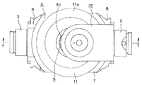
更に、図6〜7は、実願昭63−69293号(実開平1−173552号)のマイクロフィルムに記載された、より具体化されたトロイダル型無段変速機を示している。入力側ディスク2と出力側ディスク4とは円管状の入力軸18の周囲に、それぞれニードル軸受19、19を介して、回転及び軸方向の変位自在に支持している。又、ローディングカム式の押圧装置12を構成する為のカム板13は上記入力軸18の端部(図6の左端部)外周面にスプライン係合し、鍔部20によって上記入力側ディスク2から離れる方向への移動を阻止されている。又、上記出力側ディスク4には出力歯車21を、キー22、22により結合し、これら出力側ディスク4と出力歯車21とが同期して回転する様にしている。
【0011】
それぞれが前述の図5に示す様な構成を有する1対のトラニオン6、6の両端部は、それぞれ1対の支持板23、23に、揺動並びに軸方向(図6の表裏方向、図7の左右方向)の変位自在に支持している。そして、上記各トラニオン6、6を構成する支持板部7の中間部に形成した円孔10部分に、基半部9aと先半部9bとを互いに平行で且つ偏心させた変位軸9の基半部9aを、回転自在に支持している。又、上記各支持板部7の内側面から突出した、上記各変位軸9の先半部9bの周囲にパワーローラ11を、回転自在に支持している。
【0012】
尚、上記1対のトラニオン6、6毎に設けた1対の変位軸9、9は、上記入力軸18に関し、180度反対側位置に設けている。又、これら各変位軸9、9の先半部9bが基半部9aに対し偏心している方向は、上記入力側、出力側両ディスク2、4の回転方向に関して同方向(図7で左右逆方向)としている。又、偏心方向は、前記入力軸18の配設方向に対してほぼ直行する方向としている。従って前記各パワーローラ11、11は、上記入力軸18の配設方向に若干の変位自在に支持される。この結果、前記押圧装置12が発生するスラスト荷重に基づく構成各部材の弾性変形等に起因して、上記各パワーローラ11、11が上記入力軸18の軸方向に変位する傾向となった場合でも、構成各部材に無理な力を加える事なく、この変位を吸収できる。
【0013】
又、上記各パワーローラ11、11の外側面と上記各トラニオン6、6を構成する支持板部7の内側面との間には、上記パワーローラ11の外側面の側から順に、スラスト転がり軸受であるスラスト玉軸受24とスラストニードル軸受25とを設けている。このうちのスラスト玉軸受24は、上記各パワーローラ11に加わるスラスト方向の荷重を支承しつつ、これら各パワーローラ11の回転を許容するものである。この様なスラスト玉軸受24はそれぞれ、複数個ずつの玉26、26と、これら各玉26、26を転動自在に保持する円環状の保持器27と、円環状の外輪28とから構成している。又、上記各スラスト玉軸受24の内輪軌道は上記各パワーローラ11の外側面に、外輪軌道は上記各外輪28の内側面に、それぞれ形成している。
【0014】
又、上記スラストニードル軸受25は、上記各トラニオン6、6を構成する支持板部7の内側面と上記外輪28の外側面との間に挟持している。この様なスラストニードル軸受25は、上記各パワーローラ11から上記各外輪28に加わるスラスト荷重を支承しつつ、これら各パワーローラ11及び外輪28が、前記各変位軸9の基半部9aを中心として揺動変位する事を許容する。
【0015】
更に、上記各トラニオン6、6の一端部(図7の左端部)にはそれぞれ駆動ロッド29を結合し、各駆動ロッド29の中間部外周面に駆動ピストン30を固設している。そして、これら各駆動ピストン30を、それぞれ駆動シリンダ31内に油密に嵌装している。
【0016】
上述の様に構成するトロイダル型無段変速機の場合、入力軸18の回転は、押圧装置12を介して入力側ディスク2に伝えられる。そして、この入力側ディスク2の回転が、1対のパワーローラ11、11を介して出力側ディスク4に伝えられ、更にこの出力側ディスク4の回転が、出力歯車21より取り出される。
【0017】
入力軸18と出力歯車21との間の回転速度比を変える場合には、上記1対の駆動ピストン30、30を互いに逆方向に変位させる。これら各駆動ピストン30、30の変位に伴って前記1対のトラニオン6、6が、互いに逆方向に変位し、例えば図7の下側のパワーローラ11が同図の右側に、同図の上側のパワーローラ11が同図の左側に、それぞれ変位する。この結果、これら各パワーローラ11、11の周面11a、11aと前記入力側ディスク2及び出力側ディスク4の内側面2a、4aとの当接部に作用する、接線方向の力の向きが変化する。そして、この力の向きの変化に伴って前記各トラニオン6、6が、支持板23、23に枢支された枢軸5、5を中心として、互いに逆方向に揺動する。
【0018】
この結果、前述の図3〜4に示した様に、上記各パワーローラ11、11の周面11a、11aと上記各内側面2a、4aとの当接位置が変化し、前記入力軸18と出力歯車21との間の回転速度比が変化する。又、これら入力軸18と出力歯車21との間で伝達するトルクが変動し、構成各部材の弾性変形量が変化すると、上記各パワーローラ11、11及びこれら各パワーローラ11に付属の外輪28が、前記各変位軸9の基半部9aを中心として僅かに回動する。これら各外輪28の外側面と上記各トラニオン6を構成する支持板部7の内側面との間には、前記各スラストニードル軸受25が存在する為、上記回動は円滑に行なわれる。従って、上述の様に各変位軸9、9の傾斜角度を変化させる為の力が小さくて済む。
【0019】
【発明が解決しようとする課題】
上述の様なトロイダル型無段変速機の運転時に、上記各トラニオン6、6の内側面側に回転自在に支持されたパワーローラ11には、入力側、出力側両ディスク2、4の内側面2a、4aからスラスト荷重が加わる。そしてこのスラスト荷重は、スラスト玉軸受24及びスラストニードル軸受25を介して上記各トラニオン6を構成する支持板部7の内側面に伝達される。従って、トロイダル型無段変速機の運転時に上記各トラニオン6、6は、図5に誇張して示す様に、内側面側が凹面となる方向に、僅かとは言え弾性変形する。
【0020】
そして、この弾性変形量が大きくなると、上記スラスト玉軸受24を構成する転動体である玉26、26及びスラストニードル軸受25を構成するニードルに加わるスラスト荷重が不均一になる。即ち、上記各トラニオン6の弾性変形の結果、これら各トラニオン6を構成する支持板部7の内側面と上記各パワーローラ11の外側面との距離が不均一になる。そして、これら両面同士の距離が大きくなった部分に存在する転動体に加わるスラスト荷重が小さくなる代わりに、この距離が小さくなった部分に存在する転動体に加わるスラスト荷重が大きくなる。この結果、一部の転動体に過大なスラスト荷重が加わり、この一部の転動体と当該転動体の転動面が当接している軌道面との当接圧が過大となって、これら転動面及び軌道面の疲れ寿命が著しく短くなる。又、図8のA部の様に、上記トラニオン6の両端部に設けた各枢軸5、5の基端部に応力が集中して、過大なトルクが入力された場合には、この部分に亀裂等の損傷が発生し易くなる。従来は、上記トラニオン6の肉厚を大きくして、この様な損傷が発生するのを防止していたが、重量やコストが増大する原因となる為、好ましくない。
【0021】
又、トロイダル型無段変速機の運転時に上記各パワーローラ11には、前記入力側ディスク2の回転方向の力が加わる。即ち、これら各パワーローラ11の周面11aと入力側ディスク2の内側面2aとの当接部では、この入力側ディスク2から上記各パワーローラ11にトルクを伝達する事に伴って、この入力側ディスク2の回転方向の力が加わる。又、上記各パワーローラ11の周面11aと前記出力側ディスク4の内側面4aとの当接部では、このパワーローラ11からこの出力側ディスク4にトルクを伝達する事に伴う反作用として、この出力側ディスク4の回転方向と反対方向で上記入力側ディスク2の回転方向の力が加わる。この結果、上記各パワーローラ11及びこれら各パワーローラ11を支持した変位軸9の先半部9bには、図8の矢印α方向又は矢印β方向の力が加わり、この変位軸9が当該矢印方向に傾斜する傾向になる。
【0022】
この様にして変位軸9が傾斜し、この変位軸9の先半部9bに支持されたパワーローラ11の位置がずれると、このパワーローラ11の周面11aと上記各ディスク2、4の内側面2a、4aとの接触点が所定位置からずれ、変速動作が不安定になる。この様な変速動作の不安定な状態は、上記変位軸9が前記トラニオン6に対し傾斜した場合だけでなく、このトラニオン6が図5に示す様に弾性変形し、このトラニオン6に支持された変位軸9の先半部9bの位置がずれる事によっても生じる。又、上述の様に変位軸9がトラニオン6に対し傾斜した場合には、図8のB部の様に、この変位軸9の基端部とトラニオン6との係合部に応力が集中して、この部分に亀裂等の損傷が発生し易くなる。この部分に就いても従来は、肉厚を大きくして損傷が発生するのを防止していたが、重量やコストが増大する原因となる為、好ましくない。
【0023】
これに対して、特開平11−201252号公報には、図9〜10に示す様に、トラニオン6の内側面側に片持ち梁式の支持板32を設け、この支持板32の先端部により、変位軸9の先端部を支持した構造が記載されている。この様な構造によれば、この変位軸9がトラニオン6に対し傾斜する事は防止できるが、このトラニオン6が図5に示す様に弾性変形する事を防止する事はできない。従って、この弾性変形に基づいて、構成各部に過大な応力が加わる事も、この弾性変形に基づいて上記トラニオン6の先半部9bの位置がずれる事も防止できない。本発明は、この様な事情に鑑みて、各種不都合の原因となるトラニオン6の弾性変形を防止すべく発明したものである。
【0024】
【課題を解決するための手段】
本発明のトロイダル型無段変速機は、前述した従来から知られているトロイダル型無段変速機と同様に、互いの内側面同士を対向させた状態で、互いに同心に、且つ回転自在に支持された第一、第二のディスクと、これら第一、第二のディスクの中心軸に対し捻れの位置にある枢軸を中心として揺動するトラニオンと、このトラニオンを構成する支持板部の中間部に、この支持板部の内側面から突出する状態で支持された変位軸と、この変位軸の周囲に回転自在に支持された状態で、上記第一、第二の両ディスクの間に挟持されたパワーローラと、このパワーローラの外側面に添設して設けられ、このパワーローラに加わるスラスト方向の荷重を支承しつつ、このパワーローラの回転を許容するスラスト転がり軸受とを備える。そして、上記トラニオンは、上記支持板部の長さ方向両端部に1対の折れ曲がり壁部を、この支持板部の内側面側に折れ曲がる状態で形成し、これら各折れ曲がり壁部の外側面に上記各枢軸を、互いに同心に設けたものである。
【0025】
特に、本発明のトロイダル型無段変速機に於いては、上記各トラニオンを構成する1対の折れ曲がり壁部の先端部同士を連結部材により連結する。そして、上記各パワーローラを、この連結部材と上記支持板部との間に配置している。
更に好ましくは、上記支持板部と上記連結部材との互いに整合する位置に、互いに同心の円孔を形成する。そして、上記変位軸の基半部を上記支持板部に形成した円孔に、この変位軸の先端部を上記連結部材に形成した円孔に、それぞれ回転自在に支持する。
【0026】
【作用】
上述の様に構成する本発明のトロイダル型無段変速機の場合には、前述した従来のトロイダル型無段変速機と同様の作用により、第一、第二の両ディスク同士の間で回転力の伝達を行ない、又、これら両ディスクの回転速度の比を調節する。
特に、本発明のトロイダル型無段変速機の場合には、トラニオンの長さ方向両端部に設けた1対の折れ曲がり壁部の先端部同士を連結部材により連結している為、このトラニオンを構成する支持板部の内側面にスラスト荷重が加わった場合でも、このトラニオンが弾性変形しにくい。この為、トラニオンの弾性変形に基づいて発生する、前述した様な各種不都合を防止できる。
更に、変位軸の先端部を連結部材に対し回転自在に支持すれば、この変位軸がトラニオンに対し傾斜する事も防止できて、この変位軸の傾斜に基づいて発生する、前述した様な不都合をなくせる。
【0027】
【発明の実施の形態】
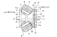
図1は、請求項1にのみ対応する、本発明の実施の形態の第1例を示している。尚、本発明の特徴は、トロイダル型無段変速機の運転時にトラニオン6を構成する支持板部7の内側面に、パワーローラ11からスラスト玉軸受24及びスラストニードル軸受25を介して加わるスラスト荷重に拘らず、上記支持板部7が弾性変形するのを防止する為の構造にある。その他の部分の構造及び作用は、図6〜7に示した構造を含め、従来から知られているトロイダル型無段変速機の場合と同様である。よって、重複する図示並びに説明は、省略若しくは簡略にし、以下、本発明の特徴部分を中心に説明する。
【0028】
本発明のトロイダル型無段変速機を構成するトラニオン6は、前述した従来構造の場合と同様に、上記支持板部7の長さ方向(図1の左右方向)両端部に1対の折れ曲がり壁部8、8を、この支持板部7の内側面側(図1の上側)に折れ曲がる状態で形成している。そして、上記各折れ曲がり壁部8、8の外側面に枢軸5、5を、互いに同心に設けている。
【0029】
更に、本発明のトロイダル型無段変速機を構成するトラニオン6の場合には、上記各1対の折れ曲がり壁部8、8の先端部同士を、連結部材33により連結している。この連結部材33は、鋼等の十分な剛性を有する材料に、鍛造加工の如き、大きな剛性を得られる加工を施す事により橋状に造ったもので、連結板部34の長さ方向(図1の左右方向)両端部に折れ曲がり板部35、35を、上記トラニオン6側に折り曲げた状態で形成している。
【0030】
この様な連結部材33は、このトラニオン6に、変位軸9、パワーローラ11、スラスト玉軸受24、スラストニードル軸受25を組み付けた後、上記トラニオン6に対し結合固定する。即ち、上記パワーローラ11を跨ぐ様にして、上記各折れ曲がり板部35、35の先端縁(図1の下端縁)を上記各折れ曲がり壁部8、8の先端縁(図1の上端縁)に突き当て、請求項3に記載した様に、更に図示しないねじ或はピンにより、上記各折れ曲がり板部35、35と上記各折れ曲がり壁部8、8とを結合する事により、上記トラニオン6に対し結合固定している。
【0031】
この連結部材33をトラニオン6に結合固定した状態で上記パワーローラ11は、上記連結部材33と上記トラニオン6の支持板部7との間に配置された状態となる。但し、上記パワーローラ11のうちで、入力側、出力側両ディスク2、4の内側面2a、4a(図3、4、6参照)と当接する部分は、上記連結部材33の側縁から露出している。上記パワーローラ11の周面11aの一部で、この様に連結部材33の側縁から露出した部分が、上記各内側面2a、4aに当接自在とする為、上記トラニオン6の揺動に拘らず、上記各ディスク2、4と干渉しない様に、上記連結部材33の形状及び大きさを設定する。この点に関しては、図9〜10に示した従来構造の場合と同様である。
【0032】
上述の様に構成する本発明のトロイダル型無段変速機の場合には、上記トラニオン6の長さ方向両端部に設けた1対の折れ曲がり壁部8、8の先端部同士を連結部材33により連結している為、このトラニオン6の曲げ剛性が向上する。この為、トロイダル型無段変速機の運転に伴ってこのトラニオン6を構成する支持板部7の内側面に、図1で下向きのスラスト荷重が加わった場合でも、上記トラニオン6が弾性変形しにくい。即ち、このトラニオン6の支持板部7が、前述の図5に示す様にその内側面が凹面となる方向に弾性変形する際には、上記1対の折れ曲がり壁部8、8の先端縁同士の間隔が変化する(縮まる)。これに対して本発明のトロイダル型無段変速機を構成するトラニオン6の場合には、上記1対の折れ曲がり壁部8、8の先端縁同士を上記連結部材33により連結する事で、この先端縁同士の間隔が変化しない様にしている。この為、上記トラニオン6の弾性変形が抑えられ、この弾性変形に基づいて発生する、前述した様な各種不都合を防止できる。
【0033】
即ち、本発明のトロイダル型無段変速機を構成するトラニオン6は、過大なトルクが入力された場合でも、上記トラニオン6の両端部に設けた各枢軸5、5の基端部に応力が集中する事がなく、このトラニオン6の肉厚を特に大きくしなくても、上記各枢軸5、5の基端部分に亀裂等の損傷が発生しにくくできる。この為、重量やコストの低減を図れる。又、上記トラニオン6の変形に基づく変位軸9の傾斜を防止し、この変位軸9の先半部9bに支持したパワーローラ11の位置がずれるのを抑える事ができるので、変速動作を安定させる事ができる。
【0034】
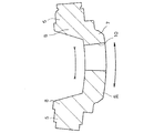
次に、図2は、請求項1〜2に対応する、本発明の実施の形態の第2例を示している。本例の場合には、トラニオン6を構成する支持板部7と、連結部材33aを構成する連結板部34aとの互いに整合する位置に、互いに同心の円孔10、36を形成している。そして、変位軸9Aの基半部9a´を上記支持板部7に形成した円孔10に、この変位軸9Aの先半部9b´を上記連結板部34aに形成した円孔36に、それぞれ転がり軸受等の軸受により、回転自在に支持している。
【0035】
この為に、上記変位軸9Aを構成する先半部9b´の先端部には、この変位軸9Aの基半部9a´と同心の枢支部37を設け、この枢支部37を上記円孔36内に、回転自在に支持している。又、上記変位軸9Aの両端部に設けた互いに同心の基半部9a´及び枢支部37の間に存在し、これら両部9a´、37に対し偏心した、上記先半部9b´の周囲にパワーローラ11を組み付け自在とする為に、上記変位軸9Aを2分割自在な構造としている。即ち、上記先半部9b´のうち、上記基半部9a´寄り部分に、スプライン係合部、断面小判形の非円形嵌合部等の、嵌合結合部38を設けている。上記先半部9b´の周囲にパワーローラ11を組み付ける際には、上記基半部9a´と上記先半部9b´とを、上記パワーローラ11の反対側から互いに近づけ合い、このパワーローラ11の内側で、上記嵌合結合部38を結合する。
【0036】
上述の様に構成する本例のトロイダル型無段変速機の場合には、上記変位軸9Aの先端部に設けた枢支部37を連結部材33aに対し回転自在に支持し、この変位軸9Aを両持支持しているので、この変位軸9Aがトラニオン6に対し傾斜する事も防止できる。この為、この変位軸9Aの傾斜に基づいて発生する、前述した様な不都合を、即ち変速動作が不安定になる事をより確実に防止できる。
【0037】
【発明の効果】
本発明のトロイダル型無段変速機は、以上に述べた通り構成され作用する為、変速動作が安定し、しかも軽量且つ耐久性の優れたトロイダル型無段変速機を実現できる。
【図面の簡単な説明】
【図1】本発明の実施の形態の第1例を示す、図7の下側に配置したトラニオンに相当するトラニオンを取り出して示す断面図。
【図2】同第2例を示す、図1と同様の図。
【図3】従来から知られているトロイダル型無段変速機の基本的構成を、最大減速時の状態で示す側面図。
【図4】同じく最大増速時の状態で示す側面図。
【図5】トラニオンの具体的形状を、スラスト荷重により弾性変形した状態で示す断面図。
【図6】従来の具体的構造の1例を示す断面図。
【図7】図6のX−X断面図。
【図8】従来構造で、トラニオン、変位軸、パワーローラに加わる力を説明する為の、図1〜2と同様の図。
【図9】従来から知られている、変位軸の傾斜防止の為の構造の1例を、トラニオンの内側面側から見た状態で示す平面図。
【図10】図9のY−Y断面図。
【符号の説明】
1 入力軸
2 入力側ディスク
2a 内側面
3 出力軸
4 出力側ディスク
4a 内側面
5 枢軸
6 トラニオン
7 支持板部
8 折れ曲がり壁部
9、9A 変位軸
9a、9a´ 基半部
9b、9b´ 先半部
10 円孔
11 パワーローラ
11a 周面
12 押圧装置
13 カム板
14 保持器
15 ローラ
16 カム面
17 カム面
18 入力軸
19 ニードル軸受
20 鍔部
21 出力歯車
22 キー
23 支持板
24 スラスト玉軸受
25 スラストニードル軸受
26 玉
27 保持器
28 外輪
29 駆動ロッド
30 駆動ピストン
31 駆動シリンダ
32 支持板
33、33a 連結部材
34、34a 連結板部
35 折れ曲がり板部
36 円孔
37 枢支部
38 嵌合結合部
[0001]
BACKGROUND OF THE INVENTION
The toroidal-type continuously variable transmission according to the present invention is used, for example, as a transmission unit for an automatic transmission for automobiles or as a transmission for various industrial machines.
[0002]
[Prior art]
The use of a toroidal type continuously variable transmission as schematically shown in FIGS. This toroidal-type continuously variable transmission, for example, as disclosed in Japanese Utility Model Laid-Open No. 62-71465, supports an input-side disk 2 that is a first disk concentrically with the input shaft 1. The output side disk 4 as the second disk is fixed to the end of the output shaft 3 arranged concentrically with the output side. On the inner side of the casing containing the toroidal type continuously variable transmission, trunnions 6 and 6 are provided that swing around pivots 5 and 5 that are twisted with respect to the input shaft 1 and the output shaft 3.
[0003]
That is, as shown in FIG. 5 and FIG. 7 described later, each trunnion 6 has a pair of bent wall portions 8 and 8 at both ends in the length direction of the support plate portion 7 (left and right direction in FIGS. 5 and 7). The support plate portion 7 is formed so as to be bent on the inner surface side (upper side in FIG. 5). The pivots 5 and 5 are provided concentrically with each other on the outer side surfaces (surfaces opposite to the support plate 7) of the bent wall portions 8 and 8, respectively. In addition, a circular hole 10 is formed in the intermediate portion of the support plate portion 7 to support the base half portion of the displacement shaft 9 described below.
[0004]
A base half portion of the displacement shaft 9 is supported in the circular hole 10 formed in the intermediate portion of the support plate portion 7 constituting each trunnion 6, 6 having such a configuration. Then, by swinging the trunnions 6 and 6 around the pivots 5 and 5, the inclination angle of the displacement shaft 9 supported at the intermediate portion of the trunnions 6 and 6 can be freely adjusted. Further, among the displacement shafts 9 whose base halves are supported by the respective trunnions 6, 6, the power rollers 11 are respectively rotated around the tip halves protruding from the inner side surfaces of the respective trunnions 6, 6. Supports freely. The power rollers 11 and 11 are sandwiched between the input side and output side disks 2 and 4. In addition, the base half part and the front half part of each said displacement shaft 9 and 9 are mutually eccentric.
[0005]
The inner side surfaces 2a and 4a of the input side and output side disks 2 and 4 facing each other have concave surfaces obtained by rotating a cross section of an arc centering on the pivot 5 or a curve close to such an arc. There is no. And the peripheral surfaces 11a and 11a of each power roller 11 and 11 formed in the spherical convex surface are made to contact | abut each said inner surface 2a and 4a.
[0006]
A loading cam type pressing device 12 is provided between the input shaft 1 and the input side disc 2, and the pressing device 12 elastically presses the input side disc 2 toward the output side disc 4. Yes. The pressing device 12 includes a cam plate 13 that rotates together with the input shaft 1 and a plurality of (for example, four) rollers 15 and 15 held by a cage 14. A cam surface 16 that is an uneven surface extending in the circumferential direction is formed on one side surface (left side surface in FIGS. 3 to 4) of the cam plate 13, and the outer surface (FIGS. 3 to 4) of the input side disk 2 is formed. A similar cam surface 17 is also formed on the right side surface of FIG. The plurality of rollers 15 and 15 are supported so as to be rotatable about a radial axis with respect to the center of the input shaft 1.
[0007]
When the toroidal type continuously variable transmission configured as described above is used, when the cam plate 13 is rotated with the rotation of the input shaft 1, the plurality of rollers 15, 15 are moved by the cam surface 16 to the input side disk 2. It is pressed by the cam surface 17 provided on the outer surface. As a result, the input side disk 2 is pressed against the plurality of power rollers 11, 11, and at the same time, the pair of cam surfaces 16, 17 are pressed against the rolling surfaces of the plurality of rollers 15, 15. Based on the above, the input side disk 2 rotates. Then, the rotation of the input side disk 2 is transmitted to the output side disk 4 via the power rollers 11, 11, and the output shaft 3 fixed to the output side disk 4 rotates.
[0008]
When the rotational speed of the input shaft 1 and the output shaft 3 is changed, and when the deceleration is first performed between the input shaft 1 and the output shaft 3, the trunnions 6 and 6 are swung around the pivot shafts 5 and 5. As shown in FIG. 3, the peripheral surfaces 11a and 11a of the power rollers 11 and 11 are respectively formed on a portion near the center of the inner side surface 2a of the input side disk 2 and a portion near the outer periphery of the inner side surface 4a of the output side disk 4. The displacement shafts 9 and 9 are inclined so as to contact each other.
[0009]
On the contrary, when the speed is increased, the trunnions 6, 6 are swung so that the peripheral surfaces 11a, 11a of the power rollers 11, 11 are as shown in FIG. The displacement shafts 9 and 9 are inclined so as to abut the outer peripheral portion of 2a and the central portion of the inner side surface 4a of the output side disk 4, respectively. If the inclination angle of each of the displacement shafts 9 and 9 is set intermediate between those shown in FIGS. 3 and 4, an intermediate gear ratio can be obtained between the input shaft 1 and the output shaft 3.
[0010]
6 to 7 show a more specific toroidal type continuously variable transmission described in the microfilm of Japanese Utility Model Application No. 63-69293 (Japanese Utility Model Laid-Open No. 1-173552). The input side disk 2 and the output side disk 4 are supported around a cylindrical input shaft 18 through needle bearings 19 and 19 so as to be freely rotatable and axially displaceable. Further, the cam plate 13 for constituting the loading cam type pressing device 12 is spline-engaged with the outer peripheral surface of the end portion (left end portion in FIG. 6) of the input shaft 18, and from the input side disk 2 by the flange portion 20. Movement away is prevented. An output gear 21 is coupled to the output disk 4 by keys 22 and 22 so that the output disk 4 and the output gear 21 rotate in synchronization.
[0011]
Both ends of the pair of trunnions 6 and 6 each having the configuration shown in FIG. 5 are respectively oscillated and axially directed to the pair of support plates 23 and 23 (front and back directions in FIG. 6, FIG. 7). The left and right directions are supported so as to be freely displaceable. Then, a base of the displacement shaft 9 in which the base half portion 9a and the tip half portion 9b are parallel to each other and eccentric to the circular hole 10 portion formed in the intermediate portion of the support plate portion 7 constituting each trunnion 6,6. The half part 9a is rotatably supported. The power roller 11 is rotatably supported around the front half 9b of each displacement shaft 9 protruding from the inner surface of each support plate 7.
[0012]
A pair of displacement shafts 9 and 9 provided for each pair of trunnions 6 and 6 is provided at a position 180 degrees opposite to the input shaft 18. Further, the direction in which the tip half 9b of each of the displacement shafts 9 and 9 is eccentric with respect to the base half 9a is the same as the rotation direction of the input side and output side disks 2 and 4 (reverse left and right in FIG. 7). Direction). The eccentric direction is a direction substantially perpendicular to the direction in which the input shaft 18 is disposed. Accordingly, the power rollers 11 and 11 are supported so as to be slightly displaceable in the direction in which the input shaft 18 is disposed. As a result, even when each of the power rollers 11, 11 tends to be displaced in the axial direction of the input shaft 18 due to elastic deformation of each constituent member based on the thrust load generated by the pressing device 12. This displacement can be absorbed without applying an excessive force to the constituent members.
[0013]
Further, a thrust rolling bearing is arranged in order from the outer surface side of the power roller 11 between the outer surface of each of the power rollers 11 and 11 and the inner surface of the support plate portion 7 constituting each of the trunnions 6 and 6. A thrust ball bearing 24 and a thrust needle bearing 25 are provided. Of these, the thrust ball bearing 24 supports the rotation of each power roller 11 while supporting the load in the thrust direction applied to each power roller 11. Such a thrust ball bearing 24 is composed of a plurality of balls 26, 26, an annular retainer 27 for holding the balls 26, 26, and an annular outer ring 28, respectively. ing. Further, the inner ring raceway of each thrust ball bearing 24 is formed on the outer side surface of each power roller 11, and the outer ring raceway is formed on the inner side surface of each outer ring 28.
[0014]
The thrust needle bearing 25 is sandwiched between the inner surface of the support plate portion 7 constituting each trunnion 6, 6 and the outer surface of the outer ring 28. Such a thrust needle bearing 25 supports the thrust load applied to each outer ring 28 from each power roller 11, and each power roller 11 and outer ring 28 is centered on the base half portion 9 a of each displacement shaft 9. Is allowed to swing and displace.
[0015]
Further, a drive rod 29 is coupled to one end portion (left end portion in FIG. 7) of each trunnion 6, 6, and a drive piston 30 is fixed to the outer peripheral surface of the intermediate portion of each drive rod 29. These drive pistons 30 are fitted in the drive cylinders 31 in an oil-tight manner.
[0016]
In the case of the toroidal-type continuously variable transmission configured as described above, the rotation of the input shaft 18 is transmitted to the input side disk 2 via the pressing device 12. Then, the rotation of the input side disk 2 is transmitted to the output side disk 4 via a pair of power rollers 11, 11, and the rotation of the output side disk 4 is taken out from the output gear 21.
[0017]
When the rotational speed ratio between the input shaft 18 and the output gear 21 is changed, the pair of drive pistons 30 and 30 are displaced in directions opposite to each other. As the drive pistons 30 and 30 are displaced, the pair of trunnions 6 and 6 are displaced in directions opposite to each other. For example, the lower power roller 11 in FIG. The power rollers 11 are displaced to the left in the figure. As a result, the direction of the tangential force acting on the contact portion between the peripheral surfaces 11a and 11a of the power rollers 11 and 11 and the inner surfaces 2a and 4a of the input side disk 2 and the output side disk 4 changes. To do. The trunnions 6 and 6 swing in opposite directions around the pivots 5 and 5 pivotally supported by the support plates 23 and 23 as the force changes.
[0018]
As a result, as shown in FIGS. 3 to 4 described above, the contact position between the peripheral surfaces 11a and 11a of the power rollers 11 and 11 and the inner surfaces 2a and 4a is changed. The rotational speed ratio with the output gear 21 changes. When the torque transmitted between the input shaft 18 and the output gear 21 fluctuates and the amount of elastic deformation of each constituent member changes, the power rollers 11 and 11 and the outer ring 28 attached to the power rollers 11 are provided. However, it slightly rotates around the base half 9a of each displacement shaft 9. Since the thrust needle bearings 25 exist between the outer side surfaces of the outer rings 28 and the inner side surfaces of the support plate portions 7 constituting the trunnions 6, the rotation is performed smoothly. Therefore, as described above, the force for changing the inclination angle of each displacement shaft 9, 9 can be small.
[0019]
[Problems to be solved by the invention]
During operation of the toroidal type continuously variable transmission as described above, the power roller 11 rotatably supported on the inner side surface of each trunnion 6, 6 has inner surfaces of both the input side and output side disks 2, 4. Thrust load is applied from 2a, 4a. The thrust load is transmitted to the inner surface of the support plate portion 7 constituting each trunnion 6 through the thrust ball bearing 24 and the thrust needle bearing 25. Therefore, when the toroidal continuously variable transmission is operated, each of the trunnions 6 and 6 is elastically deformed, albeit slightly, in a direction in which the inner side surface becomes a concave surface, as exaggeratedly shown in FIG.
[0020]
When the amount of elastic deformation increases, the thrust loads applied to the balls 26 and 26 that are rolling elements constituting the thrust ball bearing 24 and the needles constituting the thrust needle bearing 25 become non-uniform. That is, as a result of the elastic deformation of each trunnion 6, the distance between the inner surface of the support plate portion 7 constituting each trunnion 6 and the outer surface of each power roller 11 becomes uneven. Then, instead of reducing the thrust load applied to the rolling elements existing in the portion where the distance between both surfaces is increased, the thrust load applied to the rolling elements existing in the portion where the distance is reduced is increased. As a result, an excessive thrust load is applied to some of the rolling elements, and the contact pressure between the part of the rolling elements and the raceway surface with which the rolling surface of the rolling element abuts becomes excessive. The fatigue life of the moving and raceway surfaces is significantly shortened. Also, as shown in FIG. 8A, when stress is concentrated on the base ends of the pivots 5 and 5 provided at both ends of the trunnion 6, and excessive torque is input, Damage such as cracks is likely to occur. Conventionally, the thickness of the trunnion 6 has been increased to prevent such damage, but this is not preferable because it causes an increase in weight and cost.
[0021]
Further, a force in the rotational direction of the input side disk 2 is applied to each power roller 11 during operation of the toroidal continuously variable transmission. That is, at the contact portion between the peripheral surface 11a of each of the power rollers 11 and the inner surface 2a of the input side disk 2, the input side disk 2 transmits the torque to the power rollers 11 to transmit the input. A force in the rotational direction of the side disk 2 is applied. Further, at the contact portion between the peripheral surface 11a of each power roller 11 and the inner side surface 4a of the output side disk 4, as a reaction accompanying the transmission of torque from the power roller 11 to the output side disk 4, A force in the rotational direction of the input side disk 2 is applied in a direction opposite to the rotational direction of the output side disk 4. As a result, a force in the direction of arrow α or arrow β in FIG. 8 is applied to each of the power rollers 11 and the first half portion 9b of the displacement shaft 9 that supports the power rollers 11, and the displacement shaft 9 is moved to the arrows. It tends to tilt in the direction.
[0022]
When the displacement shaft 9 is inclined in this way and the position of the power roller 11 supported by the front half 9b of the displacement shaft 9 is shifted, the inner surface of the peripheral surface 11a of the power roller 11 and the discs 2 and 4 are The contact point with the side surfaces 2a and 4a is shifted from the predetermined position, and the speed change operation becomes unstable. Such an unstable state of the speed change operation is not only when the displacement shaft 9 is inclined with respect to the trunnion 6, but the trunnion 6 is elastically deformed and supported by the trunnion 6 as shown in FIG. This also occurs when the position of the first half 9b of the displacement shaft 9 is shifted. Further, when the displacement shaft 9 is inclined with respect to the trunnion 6 as described above, stress concentrates on the engaging portion between the base end portion of the displacement shaft 9 and the trunnion 6 as shown by B portion in FIG. Thus, damage such as cracks is likely to occur in this portion. Conventionally, even though this portion has been prevented from being damaged by increasing the thickness, it is not preferable because it causes an increase in weight and cost.
[0023]
On the other hand, in JP-A-11-201252, as shown in FIGS. 9 to 10, a cantilever type support plate 32 is provided on the inner surface side of the trunnion 6, and the tip of the support plate 32 is used. The structure which supported the front-end | tip part of the displacement shaft 9 is described. According to such a structure, the displacement shaft 9 can be prevented from being inclined with respect to the trunnion 6, but the trunnion 6 cannot be prevented from being elastically deformed as shown in FIG. Therefore, it is impossible to prevent an excessive stress from being applied to each component part based on this elastic deformation, and a shift of the position of the first half part 9b of the trunnion 6 based on this elastic deformation. In view of such circumstances, the present invention has been invented to prevent elastic deformation of the trunnion 6 that causes various inconveniences.
[0024]
[Means for Solving the Problems]
The toroidal-type continuously variable transmission of the present invention is supported concentrically and rotatably with the inner surfaces facing each other, like the previously known toroidal-type continuously variable transmission. First and second discs, a trunnion that swings about a pivot that is twisted with respect to the central axes of the first and second discs, and an intermediate portion of the support plate that constitutes the trunnion Further, it is sandwiched between the first and second discs in a state where the displacement shaft is supported in a state protruding from the inner surface of the support plate portion and is rotatably supported around the displacement shaft. A power roller, and a thrust rolling bearing that is provided on the outer surface of the power roller and supports the rotation of the power roller while supporting a load in the thrust direction applied to the power roller. The trunnion is formed with a pair of bent wall portions at both ends in the longitudinal direction of the support plate portion in a state of being bent toward the inner side surface of the support plate portion, and on the outer surface of each bent wall portion. Each pivot is provided concentrically with each other.
[0025]
In particular, in the toroidal type continuously variable transmission of the present invention, the ends of the pair of bent wall portions constituting each trunnion are connected by a connecting member. And each said power roller is arrange | positioned between this connection member and the said support plate part.
More preferably, concentric circular holes are formed at positions where the support plate portion and the connecting member are aligned with each other. And the base half part of the said displacement shaft is rotatably supported by the circular hole formed in the said support plate part, and the front-end | tip part of this displacement shaft is each rotatably supported by the circular hole formed in the said connection member.
[0026]
[Action]
In the case of the toroidal type continuously variable transmission of the present invention configured as described above, the rotational force between the first and second disks is obtained by the same action as the conventional toroidal type continuously variable transmission described above. And the ratio of the rotational speeds of these two disks is adjusted.
In particular, in the case of the toroidal continuously variable transmission according to the present invention, the ends of the pair of bent wall portions provided at both ends in the longitudinal direction of the trunnion are connected to each other by a connecting member. Even when a thrust load is applied to the inner surface of the supporting plate portion, the trunnion is not easily elastically deformed. For this reason, it is possible to prevent various inconveniences such as those described above that occur due to elastic deformation of the trunnion.
Furthermore, if the distal end of the displacement shaft is supported rotatably with respect to the connecting member, the displacement shaft can be prevented from tilting with respect to the trunnion, and the inconvenience as described above is generated based on the tilt of the displacement shaft. Can be eliminated.
[0027]
DETAILED DESCRIPTION OF THE INVENTION
FIG. 1 shows a first example of an embodiment of the present invention corresponding to claim 1 only. The feature of the present invention is that the thrust load applied from the power roller 11 to the inner surface of the support plate portion 7 constituting the trunnion 6 through the thrust ball bearing 24 and the thrust needle bearing 25 during operation of the toroidal type continuously variable transmission. Regardless of this, the support plate portion 7 has a structure for preventing elastic deformation. The structure and operation of the other parts are the same as those of the conventionally known toroidal type continuously variable transmission including the structures shown in FIGS. Therefore, overlapping illustrations and descriptions will be omitted or simplified, and the following description will focus on the features of the present invention.
[0028]
The trunnion 6 constituting the toroidal-type continuously variable transmission of the present invention has a pair of bent walls at both ends in the length direction (left-right direction in FIG. 1) of the support plate 7 as in the case of the conventional structure described above. The portions 8 and 8 are formed in a state of being bent toward the inner side surface (upper side in FIG. 1) of the support plate portion 7. And the pivots 5 and 5 are provided concentrically with each other on the outer surface of each of the bent wall portions 8 and 8.
[0029]
Further, in the case of the trunnion 6 constituting the toroidal type continuously variable transmission according to the present invention, the ends of the pair of bent wall portions 8 and 8 are connected by a connecting member 33. The connecting member 33 is formed in a bridge shape by subjecting a material having sufficient rigidity such as steel to a process such as forging to obtain a large rigidity. 1 in the left-right direction) bent plate portions 35, 35 are formed at both ends so as to be bent toward the trunnion 6 side.
[0030]
Such a connecting member 33 is coupled and fixed to the trunnion 6 after the displacement shaft 9, the power roller 11, the thrust ball bearing 24 and the thrust needle bearing 25 are assembled to the trunnion 6. That is, the front edge (lower edge in FIG. 1) of each bent plate portion 35, 35 is turned to the front edge (upper edge in FIG. 1) of each bent wall portion 8, 8 so as to straddle the power roller 11. Hit, As described in claim 3, Further, the bent plate portions 35, 35 and the bent wall portions 8, 8 are connected and fixed to the trunnion 6 by screws or pins (not shown).
[0031]
The power roller 11 is disposed between the connecting member 33 and the support plate portion 7 of the trunnion 6 in a state where the connecting member 33 is coupled and fixed to the trunnion 6. However, portions of the power roller 11 that are in contact with the inner side surfaces 2a, 4a (see FIGS. 3, 4, 6) of both the input side and output side disks 2, 4 are exposed from the side edges of the connecting member 33. is doing. Since a part of the peripheral surface 11a of the power roller 11 that is exposed from the side edge of the connecting member 33 can freely contact the inner side surfaces 2a and 4a, the trunnion 6 can be swung. Regardless, the shape and size of the connecting member 33 are set so as not to interfere with the disks 2 and 4. This is the same as in the case of the conventional structure shown in FIGS.
[0032]
In the case of the toroidal type continuously variable transmission of the present invention configured as described above, the pair of bent wall portions 8 and 8 provided at both ends in the longitudinal direction of the trunnion 6 are connected to each other by the connecting member 33. Since they are connected, the bending rigidity of the trunnion 6 is improved. Therefore, even when a downward thrust load in FIG. 1 is applied to the inner side surface of the support plate portion 7 constituting the trunnion 6 as the toroidal continuously variable transmission is operated, the trunnion 6 is not easily elastically deformed. . That is, when the support plate portion 7 of the trunnion 6 is elastically deformed in the direction in which the inner surface is concave as shown in FIG. 5 described above, the tip edges of the pair of bent wall portions 8 and 8 are in contact with each other. The interval of changes (shrinks). On the other hand, in the case of the trunnion 6 constituting the toroidal-type continuously variable transmission of the present invention, the tip end edges of the pair of bent wall portions 8 and 8 are connected to each other by the connecting member 33. The distance between the edges is not changed. For this reason, the elastic deformation of the trunnion 6 is suppressed, and various inconveniences as described above that occur based on the elastic deformation can be prevented.
[0033]
That is, in the trunnion 6 constituting the toroidal continuously variable transmission according to the present invention, stress is concentrated on the base ends of the pivots 5 and 5 provided at both ends of the trunnion 6 even when excessive torque is input. Even if the thickness of the trunnion 6 is not particularly increased, the base end portions of the pivots 5 and 5 are less likely to be damaged such as cracks. For this reason, weight and cost can be reduced. Further, the displacement shaft 9 can be prevented from being inclined due to the deformation of the trunnion 6, and the shift of the position of the power roller 11 supported by the front half 9b of the displacement shaft 9 can be suppressed, so that the shifting operation is stabilized. I can do things.
[0034]
Next, FIG. 2 shows a second example of an embodiment of the present invention corresponding to claims 1 and 2. In the case of this example, concentric circular holes 10 and 36 are formed at positions where the supporting plate portion 7 constituting the trunnion 6 and the connecting plate portion 34a constituting the connecting member 33a are aligned with each other. The base half 9a 'of the displacement shaft 9A is formed in the circular hole 10 formed in the support plate portion 7, and the tip half 9b' of the displacement shaft 9A is formed in the circular hole 36 formed in the connecting plate portion 34a. It is rotatably supported by a bearing such as a rolling bearing.
[0035]
For this purpose, a distal end portion of the front half portion 9b ′ constituting the displacement shaft 9A is provided with a pivot portion 37 concentric with the base half portion 9a ′ of the displacement shaft 9A, and the pivot portion 37 is connected to the circular hole 36. Inside, it is supported rotatably. In addition, there exists between the concentric base half part 9a 'and the pivotal support part 37 provided at both ends of the displacement shaft 9A, and the periphery of the front half part 9b' is eccentric with respect to both the parts 9a 'and 37. In order to allow the power roller 11 to be assembled freely, the displacement shaft 9A has a structure that can be divided into two. That is, a fitting coupling portion 38 such as a spline engaging portion or a non-circular fitting portion having an oval cross section is provided in a portion near the base half portion 9a ′ in the front half portion 9b ′. When the power roller 11 is assembled around the front half 9b ', the base half 9a' and the front half 9b 'are brought close to each other from the opposite side of the power roller 11, and the power roller 11 The fitting coupling portion 38 is coupled to the inside.
[0036]
In the case of the toroidal type continuously variable transmission of the present example configured as described above, the pivotal support portion 37 provided at the distal end portion of the displacement shaft 9A is rotatably supported with respect to the connecting member 33a, and the displacement shaft 9A is supported. Since both ends are supported, it is possible to prevent the displacement shaft 9A from being inclined with respect to the trunnion 6. For this reason, it is possible to more reliably prevent the inconvenience as described above based on the inclination of the displacement shaft 9A, that is, the unstable shifting operation.
[0037]
【The invention's effect】
Since the toroidal type continuously variable transmission of the present invention is configured and operates as described above, it is possible to realize a toroidal type continuously variable transmission that has a stable speed change operation and is lightweight and excellent in durability.
[Brief description of the drawings]
FIG. 1 is a cross-sectional view showing a trunnion corresponding to a trunnion disposed on the lower side of FIG. 7 and showing a first example of an embodiment of the present invention.
FIG. 2 is a view similar to FIG. 1, showing the second example.
FIG. 3 is a side view showing a basic configuration of a conventionally known toroidal type continuously variable transmission in a state of maximum deceleration.
FIG. 4 is a side view showing the same state at the maximum speed increase.
FIG. 5 is a cross-sectional view showing a specific shape of a trunnion in a state in which it is elastically deformed by a thrust load.
FIG. 6 is a cross-sectional view showing an example of a conventional specific structure.
7 is a cross-sectional view taken along the line XX in FIG.
FIG. 8 is a view similar to FIGS. 1 and 2 for explaining the force applied to the trunnion, the displacement shaft, and the power roller in the conventional structure.
FIG. 9 is a plan view showing an example of a conventionally known structure for preventing the tilting of the displacement shaft as viewed from the inner side of the trunnion.
10 is a YY sectional view of FIG. 9;
[Explanation of symbols]
1 Input shaft
2 Input disk
2a Inner side
3 Output shaft
4 Output disk
4a inner surface
5 Axis
6 Trunnion
7 Support plate
8 Bending wall
9, 9A Displacement axis
9a, 9a 'base half
9b, 9b 'first half
10 hole
11 Power Roller
11a circumference
12 Pressing device
13 Cam plate
14 Cage
15 Laura
16 Cam surface
17 Cam surface
18 Input shaft
19 Needle bearing
20 Buttocks
21 Output gear
22 keys
23 Support plate
24 Thrust ball bearing
25 Thrust needle bearing
26 balls
27 Cage
28 Outer ring
29 Drive rod
30 Drive piston
31 Drive cylinder
32 Support plate
33, 33a Connecting member
34, 34a Connecting plate part
35 Bent plate
36 hole
37 pivotal
38 Fitting joint

Claims (3)

互いの内側面同士を対向させた状態で、互いに同心に、且つ回転自在に支持された第一、第二のディスクと、これら第一、第二のディスクの中心軸に対し捻れの位置にある枢軸を中心として揺動するトラニオンと、このトラニオンを構成する支持板部の中間部に、この支持板部の内側面から突出する状態で支持された変位軸と、この変位軸の周囲に回転自在に支持された状態で、上記第一、第二の両ディスクの間に挟持されたパワーローラと、このパワーローラの外側面に添設して設けられ、このパワーローラに加わるスラスト方向の荷重を支承しつつ、このパワーローラの回転を許容するスラスト転がり軸受とを備え、上記トラニオンは、上記支持板部の長さ方向両端部に1対の折れ曲がり壁部を、この支持板部の内側面側に折れ曲がる状態で形成し、これら各折れ曲がり壁部の外側面に上記各枢軸を、互いに同心に設けたものであるトロイダル型無段変速機に於いて、上記各トラニオンを構成する1対の折れ曲がり壁部の先端部同士を連結部材により連結し、上記各パワーローラを、この連結部材と上記支持板部との間に配置した事を特徴とするトロイダル型無段変速機。  The first and second discs are concentrically and rotatably supported with the inner surfaces facing each other, and are in a twisted position with respect to the central axes of these first and second discs. A trunnion that swings around the pivot axis, a displacement shaft that is supported in a state protruding from the inner surface of the support plate portion at the intermediate portion of the support plate portion that constitutes the trunnion, and freely rotatable around the displacement shaft And a power roller sandwiched between the first and second discs and an outer surface of the power roller, and a thrust load applied to the power roller is provided. A thrust rolling bearing that supports the rotation of the power roller while being supported, and the trunnion has a pair of bent wall portions at both ends in the length direction of the support plate portion, and the inner surface side of the support plate portion. Folded into a shape In the toroidal type continuously variable transmission in which the pivots are provided concentrically with each other on the outer surface of each bent wall portion, the tips of the pair of bent wall portions constituting each trunnion A toroidal continuously variable transmission characterized in that the parts are connected by a connecting member, and the power rollers are disposed between the connecting member and the support plate. 支持板部と連結部材との互いに整合する位置に、互いに同心の円孔を形成し、変位軸の基半部を上記支持板部に形成した円孔に、この変位軸の先端部を上記連結部材に形成した円孔に、それぞれ回転自在に支持した、請求項1に記載したトロイダル型無段変速機。  Concentric circular holes are formed at positions where the support plate portion and the connecting member are aligned with each other, and the distal end portion of the displacement shaft is connected to the circular hole formed at the base half of the displacement shaft in the support plate portion. The toroidal continuously variable transmission according to claim 1, wherein each of the toroidal continuously variable transmissions is rotatably supported in a circular hole formed in the member. 連結部材の長さ方向両端部に設けた各折れ曲がり板部の先端縁を各折れ曲がり壁部の先端縁に突き当てた状態で、ねじによりこれら各折れ曲がり板部とこれら各折れ曲がり壁部とを結合する事により、上記連結部材をトラニオンに対し結合固定している、請求項1〜2のうちの何れか1項に記載したトロイダル型無段変速機。The bent plate portions and the bent wall portions are coupled by screws in a state where the leading edge of each bent plate portion provided at both ends in the length direction of the connecting member is abutted against the leading edge of the bent wall portion. The toroidal type continuously variable transmission according to any one of claims 1 to 2, wherein the connecting member is coupled and fixed to the trunnion.
JP2000122648A 2000-04-24 2000-04-24 Toroidal continuously variable transmission Expired - Fee Related JP4069573B2 (en)

Priority Applications (1)

Application Number Priority Date Filing Date Title
JP2000122648A JP4069573B2 (en) 2000-04-24 2000-04-24 Toroidal continuously variable transmission

Applications Claiming Priority (1)

Application Number Priority Date Filing Date Title
JP2000122648A JP4069573B2 (en) 2000-04-24 2000-04-24 Toroidal continuously variable transmission

Publications (3)

Publication Number Publication Date
JP2001304366A JP2001304366A (en) 2001-10-31
JP2001304366A5 JP2001304366A5 (en) 2005-09-15
JP4069573B2 true JP4069573B2 (en) 2008-04-02

Family

ID=18633100

Family Applications (1)

Application Number Title Priority Date Filing Date
JP2000122648A Expired - Fee Related JP4069573B2 (en) 2000-04-24 2000-04-24 Toroidal continuously variable transmission

Country Status (1)

Country Link
JP (1) JP4069573B2 (en)

Families Citing this family (5)

* Cited by examiner, † Cited by third party
Publication number Priority date Publication date Assignee Title
DE10239232B4 (en) * 2001-08-27 2009-05-07 Nsk Ltd. Stepless toroidal transmission
JP2003207007A (en) 2002-01-17 2003-07-25 Nsk Ltd Toroidal type continuously variable transmission
JP4003122B2 (en) 2002-09-05 2007-11-07 日本精工株式会社 Power roller unit for toroidal type continuously variable transmission
JP4983363B2 (en) * 2007-04-17 2012-07-25 日本精工株式会社 Toroidal continuously variable transmission
JP5990921B2 (en) * 2012-02-09 2016-09-14 日本精工株式会社 Toroidal continuously variable transmission

Also Published As

Publication number Publication date
JP2001304366A (en) 2001-10-31

Similar Documents

Publication Publication Date Title
JP4003122B2 (en) Power roller unit for toroidal type continuously variable transmission
JP4069573B2 (en) Toroidal continuously variable transmission
JP3617267B2 (en) Toroidal continuously variable transmission
JP4135249B2 (en) Half toroidal continuously variable transmission
JP3849409B2 (en) Half toroidal continuously variable transmission
JP3899745B2 (en) Toroidal continuously variable transmission
JPH07243492A (en) Toroidal type continuously variable transmission
JP4016514B2 (en) Toroidal continuously variable transmission
JP3617265B2 (en) Toroidal continuously variable transmission
JP3820978B2 (en) Toroidal continuously variable transmission
JP3617235B2 (en) Toroidal continuously variable transmission
JP3617258B2 (en) Toroidal continuously variable transmission
JP2001050360A (en) Toroidal continuously variable transmission
JP3941275B2 (en) Toroidal continuously variable transmission
JP4721040B2 (en) Toroidal continuously variable transmission
JP2007240004A (en) Power roller unit for toroidal continuously variable transmission
JP4026237B2 (en) Toroidal continuously variable transmission
JP4211157B2 (en) Toroidal continuously variable transmission
JPH07229546A (en) Toroidal type continuously variable transmission
JP3293306B2 (en) Toroidal type continuously variable transmission
JP4013369B2 (en) Toroidal type continuously variable transmission assembly method
JPH094689A (en) Toroidal type continuously variable transmission
JPH0814350A (en) Toroidal-type continuously variable transmission
JP3849332B2 (en) Manufacturing method of disk for toroidal type continuously variable transmission
JP4280963B2 (en) Toroidal continuously variable transmission

Legal Events

Date Code Title Description
A521 Written amendment

Free format text: JAPANESE INTERMEDIATE CODE: A523

Effective date: 20050329

A621 Written request for application examination

Free format text: JAPANESE INTERMEDIATE CODE: A621

Effective date: 20050329

TRDD Decision of grant or rejection written
A977 Report on retrieval

Free format text: JAPANESE INTERMEDIATE CODE: A971007

Effective date: 20071225

A01 Written decision to grant a patent or to grant a registration (utility model)

Free format text: JAPANESE INTERMEDIATE CODE: A01

Effective date: 20071225

A61 First payment of annual fees (during grant procedure)

Free format text: JAPANESE INTERMEDIATE CODE: A61

Effective date: 20080107

R150 Certificate of patent or registration of utility model

Free format text: JAPANESE INTERMEDIATE CODE: R150

FPAY Renewal fee payment (event date is renewal date of database)

Free format text: PAYMENT UNTIL: 20110125

Year of fee payment: 3

FPAY Renewal fee payment (event date is renewal date of database)

Free format text: PAYMENT UNTIL: 20120125

Year of fee payment: 4

FPAY Renewal fee payment (event date is renewal date of database)

Free format text: PAYMENT UNTIL: 20130125

Year of fee payment: 5

FPAY Renewal fee payment (event date is renewal date of database)

Free format text: PAYMENT UNTIL: 20130125

Year of fee payment: 5

FPAY Renewal fee payment (event date is renewal date of database)

Free format text: PAYMENT UNTIL: 20140125

Year of fee payment: 6

LAPS Cancellation because of no payment of annual fees