JP3775005B2 - Threshing device - Google Patents
Threshing device Download PDFInfo
- Publication number
- JP3775005B2 JP3775005B2 JP22937997A JP22937997A JP3775005B2 JP 3775005 B2 JP3775005 B2 JP 3775005B2 JP 22937997 A JP22937997 A JP 22937997A JP 22937997 A JP22937997 A JP 22937997A JP 3775005 B2 JP3775005 B2 JP 3775005B2
- Authority
- JP
- Japan
- Prior art keywords
- chamber
- processing
- cylinder
- dust
- handling
- Prior art date
- Legal status (The legal status is an assumption and is not a legal conclusion. Google has not performed a legal analysis and makes no representation as to the accuracy of the status listed.)
- Expired - Fee Related
Links
Images


Landscapes
- Threshing Machine Elements (AREA)
Description
【0001】
【発明の属する技術分野】
この発明は、コンバインやハ−ベスタ等に利用し得る脱穀装置に関する。
【0002】
【従来の技術】
扱室と二番処理室及び排塵室を並設し、この扱室内に設けた扱歯を有する扱胴、二番処理室に設けた処理歯を有する二番処理胴、排塵室に設けた前記二番処理歯と略同高さの処理歯を有する排塵胴により処理する構成の脱穀装置が考えられている。
【0003】
【発明が解決しようとする課題】
このような構成では、穂の付いた穀稈の穂先部を扱室内で扱胴で脱穀処理し、扱室内での処理が十分でない処理物を排塵室の排塵胴で処理し、還元された二番物を二番処理室の二番処理胴で処理するので、合理的な処理作業を行うことができるが、二番処理胴の処理歯が高いと、還元された二番物に混入する穀粒に損傷を発生し易い。
【0004】
【課題を解決するための手段】
この発明は、このような課題を解決する脱穀装置を提供するものであって、つぎのような技術的手段を講じた。
すなわち、扱胴(1)を回転可能に設ける扱室(2)の前壁に穀稈供給口を形成すると共に該扱室(2)の後壁に穀稈排出口を形成し、該扱室(2)の終端部における穀稈扱ぎ口(27)とは反対の側に扱室送塵口(5)を設け、該扱室送塵口(5)に対して排塵胴(6)を設ける排塵処理室(7)の始端部を連通させると共に該排塵処理室(7)の終端部に選別室(26)に連通する排塵口(32)を設け、前記排塵胴(6)における扱室送塵口(5)に対向する部位に螺旋(37)を設けると共に該螺旋(37)の後側に多数の処理歯(8)を設けるにあたり、該各処理歯(8)を左右両端部が上方に折れ曲がったU字状に形成すると共に該各処理歯(8)の縁部を円弧状の曲面に形成し、該各処理歯(8)の取付け面(38)に孔(39)を設けて該孔(39)内における取付け面(38)の縁部(40)のうちの前記排塵胴(6)の回転方向側に位置する縁部(40)を排塵胴(6)に溶接して取り付け、前記排塵処理室(7)における排塵胴(6)の回転軌跡に沿って扱室受網(30)の網目よりも大きい網目を有する排塵処理室受網(33)を設け、前記排塵胴(6)を設ける軸(34)を前記扱室(2)に隣設する二番処理室(4)まで延設して該軸(34)によって二番処理室(4)に二番処理胴(3)を内装し、該二番処理胴(3)に多数の処理歯(9)を設けるにあたり、該各処理歯(9)を左右両端部が上方に折れ曲がったU字状に形成すると共に該各処理歯(9)の縁部を円弧状の曲面に形成して前記排塵胴(6)の処理歯(8)の高さよりも低い処理歯(9)とし、該各処理歯(9)の取付け面(38)に孔(39)を設けて該孔(39)内における取付け面(38)の縁部(40)のうちの前記二番処理胴(3)の回転方向側に位置する縁部(40)を二番処理胴(3)に溶接して取り付け、前記二番処理胴(3)の回転軌跡に沿って前記排塵処理室受網(33)の網目よりも小さい網目を有する二番処理室受網(36)を設け、二番還元装置(54)の搬送終端部を前記二番処理室(4)の始端部の上部に連通させると共に該二番処理室(4)における前記排塵処理室(7)とは反対の側に選別室(26)と連通する二番物排出口(35)を設け、前記排塵胴(6)及び二番処理胴(3)を駆動するギヤボックス(60)を扱室(2)の前壁(61)と二番処理室(4)の側壁(62)とに亘って取り付けたことを特徴とする脱穀装置とする。
【0005】
扱胴1が回転する扱室2で脱穀された穀粒と一部のわら屑は受網から漏下し選別作用を受けるが、扱室2から漏下しなかったわら屑の多い排塵物は扱室送塵口5を通って排塵処理室7に送りこまれ、その後、周速の大きい処理歯8を有する排塵胴6により処理作用を受けながら扱室送塵口5と反対側に送られる。このとき、多くの穀粒は排塵処理室7から漏下して選別作用を受ける。一方、二番処理室4に還元された二番物は、前記処理歯8より低く周速の小さい処理歯8を有する二番処理胴3によって処理されながら二番処理室4の排出口側に向けて搬送される。
【0006】
【発明の効果】
二番処理胴3の処理歯9の高さを排塵胴6の処理歯8の高さよりも低く設けているので、枝梗付着粒の単粒化を図れながらも回転時の周速が小さくなって、藁屑の混入の少ない二番物への打撃も小さくなり損傷粒の発生を抑制できる。また、藁屑の混入の多い排塵物は処理胴3の高い処理歯8によって処理を受けるので、藁屑と穀粒の分離作用が向上し処理能力を高め得る。また、この処理歯9には角部に曲面を設けているので、穀粒の損傷を防止しながらも枝梗の処理能力を高め得る。
また、処理歯8,9の取付け面38に孔39を設け、回転方向側に位置する取付け面38の縁部40を排塵胴6及び二番処理胴9に夫々溶接して取り付けることにより、二番物や排塵物との摩擦による取付け部の摩耗を防止し、剥がれがなく耐久性が向上する。
また、排塵胴6及び二番処理胴3を駆動するギヤボックス60を扱室の前壁61と二番処理室の側壁62とに取り付けているので、ギヤボックス60の大きなふらつきを防止し伝動効率もよい。
【0007】
【発明の実施の形態】
以下、本発明の実施の一形態を図面に基づいて説明する。
まず、その構成について説明すると、コンバイン10は、機体の前進方向に向かって、左右方向に所定の間隔を置いて配置した走行装置(クロ−ラ型であるが、車輪又は車輪とクロ−ラとの組合わせによる構成としてもよい)11を具備する車台12の前部に油圧式の昇降手段によって昇降自在に刈取搬送装置13を設け、該刈取搬送装置13の後方で車台12の左側部に脱穀装置14を設け、該脱穀装置14の右側部にタンク15を設け、該タンク15と刈取搬送装置13との間の空間部にキャビン16によって囲まれ各種操作レバ−や表示具等を備えた運転部17を設け、前記脱穀装置14の後側に排藁処理装置(実施例では排藁切断装置が、排藁結束装置、排藁収束装置、あるいはこれら装置の組み合わせでもよい)18を設けている。
【0008】
刈取搬送装置13は左右横方向に複数個配置した分草体19と、後方斜め上方に移動する引き起こしラグ20を有し横方向に複数個配置した引き起こし装置21と、バリカン型の刈取装置22と、刈取った穀稈を後方上方に搬送する穀稈搬送装置23とを一体に構成している。なお、刈取搬送装置13への駆動部に、例えばHSTのような変速手段(有段、無段いずれでもよい)を設けている。また、引き起こし装置21への駆動部に、例えばHSTのような変速手段(有段、無段いずれでもよい)を設けることもできる。
【0009】
脱穀装置14は機体の進行方向に回転するフィ−ドチェン24と挟扼杆25とを有する穀稈自動送り込み装置31を一側部に有し、前記穀稈搬送装置23が搬送してきた穀稈の株元部を挟持後搬送して穂先部を扱室内に送り込み脱穀する自脱型の構成であって、箱型のケ−ス内の上部に、扱室2に並んで二番処理室4と排塵処理室7とを前後に設け、その下部に選別室26を設けている。
【0010】
該扱室2は、前壁に穀稈供給口を形成し、後壁に穀稈排出口を形成し、横側壁に穀稈供給口と穀稈排出口を連通する穀稈扱ぎ口27を形成すると共に、内部に、横方向に軸芯を有する扱胴軸28を設けて、この扱胴軸28に外面に多数の扱歯29を設けた扱胴1を着脱自在に設けている。そして、扱胴1の回転軌跡にそって外周一定部分に円弧状の扱室受網30をけている。なお、該扱室2の終端部で穀稈扱ぎ口27とは反対側に扱室送塵口5を設けている。
【0011】
排塵処理室7は始端部を前記扱室送塵口5に連通し終端部を機体後壁に近接して選別室26と連通する排塵口32を設けている。そして、該排塵処理室7の内部に、扱室送塵口31に対向する部位に排塵口32に向けて排塵物を送ることができる螺旋37を設けると共に処理歯8を多数有し且つ軸芯方向を前記扱胴1の軸芯と同方向に位置させた排塵胴6を設けている。そして、処理歯8は、板材の左右両端部を上方に折り曲げてU状に形成し、しかも各縁部を円弧状の曲面を形成している。なお、排塵処理室7は排塵処理胴6の回転軌跡に沿って一定部分に扱室受網30の網目よりも大きな網目を有する排塵処理室受網33を設けている。 二番処理室4は前記扱室2の隣で排塵処理室7に直列に位置しており、排塵処理胴6を着脱自在に設け且つ二番処理室4に延設した軸34に着脱自在に取り付けた二番処理胴3を内装している。そして、該二番処理胴3は外面に板材の左右両端部を上方に折り曲げてU状に形成し且つ角部を各縁部を円弧状の曲面を形成した前記処理歯8より低い高さの多数の処理歯9を設けており、軸34は一端部を前壁に軸受を介して回転自在に設け、他端部を機体後壁に軸受を介して回転自在に設けている。
【0012】
なお、二番処理室4は二番処理胴3の回転軌跡に沿って一定部分に前記排塵処理室受網33の網目よりも小さな網目を有する二番処理室受網36を設け、また、排塵処理室7とは反対側に選別室26と連通する二番物排出口35を設けている。
さらに、実施例では二番処理胴3と排塵胴6とを同径の一個の筒体で構成しているが、分割した別個のものでもよく、前記扱胴1と同方向に回転可能に設けている。また、処理歯8,9の取付け面38には孔(実施例では矩形であるが円形、あるいは矩形と円形の組み合わせた形状でもよい)39を設け、筒体の回転方向と反対側に位置する取付け面38、及び孔39の縁部40を筒体に一体(実施例では溶接)に取り付けている。このように取り付けることにより、二番物や排塵物との摩擦による取付け部の摩耗を防止し、筒体からの剥がれがなく耐久性を向上する。
【0013】
選別室26は前記扱室2、二番処理室4及び排塵処理室7の下方位置に扱胴軸28の軸芯方向に揺動可能に設けた揺動選別棚41と、該揺動選別棚41の下方位置で選別始端側から圧風を供給する唐箕42、一番物回収樋43と一番物搬送螺旋44とを有する一番物回収装置45、二番物回収樋46と二番物搬送螺旋47とを有する二番物回収樋48を設け、側面視において、揺動選別棚41の先端部(選別終端部)の上方で排塵処理胴の処理終端部と重なる位置に時計方向に回転する排塵ファン(片吸い型のファン)49を設けている。なお、揺動選別棚41は移送棚50、チャフシ−ブ51、グレンシ−ブ52、ストロ−ラック53等を具備している。
【0014】
二番還元装置54は筒55及び筒55に内装した螺旋56を備えており、搬送始端部を前記二番物回収樋46の終端部に連通し、搬送終端部を二番処理室4の始端部の上部に連通させて側面から見て斜めに設けている。
57は揚穀始端部を前記一番物回収樋43の搬送終端部と連通し、揚穀終端部を脱穀装置14の横側部に設けたタンク15に連通する揚穀装置であり、該タンク15は下方を細く形成した中空のタンクで底部に下部螺旋(図示せず)を設けていると共に外壁にL状のチュ−ブ58を着脱自在に設けている。59は排出オ−ガである。
【0015】
ギヤボックス60は複数の歯車を噛み合わせて回転可能に内装し、二番処理胴3及び排塵胴6を駆動し得ると共に輪体及び無端帯等の伝動機構により扱胴1を回転し得る構成とし、扱室前壁61と二番処理室側壁62とに亘ってねじ63で着脱自在に取り付けている。
つぎに、その作用について説明する。
【0016】
まず、運転者はコンバインの運転部の座席に座り、駐車ブレ−キペダルを踏み込んでキ−をキ−スイッチに入れエンジンを起動すると、エンジンから出力された動力は伝動機構を介して機体の回転各部に伝動される。そして、スロットルレバ−を回動してエンジンを所定回転数に選択すると共に、副変速レバ−を所望位置に回動して、例えば標準を選択し、さらに脱穀レバ−及び刈取レバ−を操作して機体の回転各部を駆動し、収穫作業の準備を終えると、駐車ブレ−キペダルの踏み込みを解除し、つづいて変速レバ−を側に回動して機体を前進させると共に操作レバ−を前後方向に傾倒して刈取搬送装置の高さ位置を決め、または左右に傾倒して機体の進行方向を変更しながら分草体を所定の条間に合わせる。
【0017】
すると、引き起こしケ−スに沿って斜め後方上方に移動する引き起こしラグ20で引き起こされた穀稈の株元部は、刈取装置22によって切断されて刈取搬送装置13に受け継がれ後方上方に搬送される。そして、搬送終端部に到達した穀稈は穀稈自動送り込み装置31に挟持されて後方に搬送され、排藁処理装置18に送り込まれて処理されるが、穀稈の穂部はその途中で扱室内に送り込まれ回転する扱胴1の扱歯29及び扱室受網30によって脱穀処理される。
【0018】
これにより生じた小さなわら屑を含む多くの穀粒は扱室受網30から漏下して下方の往復揺動する揺動選別棚41に落下し移送選別作用を受ける。そして、この揺動選別棚41から漏下した漏下物は、唐箕42によって斜め上方に送られて来る選別風を受け、風選された穀粒が一番物回収装置45に回収される。そして、回収された穀粒は一番物回収装置45の一番物回収樋43と一番物回収螺旋44によって一側部に搬送された後に揚穀装置57によってタンク15に送りこまれる。その後、穀粒がタンク15に充満又は作業者がタンク15から穀粒を排出する必要がある場合は、排出操作をしてチュ−ブ58、排出オ−ガ59を介して機外に排出する。
【0019】
一方、漏下しなかった脱穀物は扱室2の終端部に送られて扱室送塵口5から排塵処理室7に送りこまれ、排塵処理胴3の螺旋37によって速やかに後方に搬送された後処理歯8によってさらに処理作用を受けながら後方に移動する。この間、穀粒は排塵処理室受網33から漏下して下方の揺動選別棚41に落下し選別作用を受ける。この処理歯8による処理作業において、広幅で且つ角部に曲面を設けているので、穀粒の損傷を防止しながらも枝梗の処理を高め得る。
【0020】
そして、排塵処理室受網33から漏下しなかった多くのわら屑を含む処理物は、排塵口32から排出され、揺動選別棚41によって選別終端部に送られてきた被選別物と一緒に唐箕42による圧風と排塵ファン49による排塵作用によって選別作用を受けながら機外に排出される。なお、一部の穀粒やカギ又等の未処理粒は揺動選別棚41から漏下して二番物回収装置48に回収される。
【0021】
選別作業において、二番物回収装置48に回収された二番物は、二番物回収樋46と二番物搬送螺旋47によって一側に向けて搬送され、その後、二番還元装置54に引き継がれて筒55及び螺旋56により上方に搬送される。そして、二番物は、搬送終端部に達すると、螺旋56の上端部に設けた排出体によって排出口A通って二番処理室4の処理始端部上部から排出される。
【0022】
この二番物は、処理歯9を有し矢印方向に回転する二番処理胴3と二番処理室受網36によって処理作用を受けながら排塵処理胴3とは反対側に送られる。この処理歯9による処理作業において、広幅で且つ角部に曲面を設けているので、穀粒の損傷を防止しながらも枝梗の処理を高め得る。そして、二番処理室受網36から漏下した二番物は、下方で扱胴軸28の軸芯方向に揺動する揺動選別棚41に落下し選別され、漏下しなかった二番物は二番物排出口35から揺動選別棚41に排出され後方に搬送されながら選別作用を受ける。
【0023】
二番処理胴3の処理歯9の高さは排塵胴6の処理歯8の高さよりも低く設けているので、カギ又や枝梗付着粒の単粒化を図れながらも回転時の周速が小さくなって、藁屑の混入の少ない二番物への打撃も小さくなり損傷粒の発生を抑制できる。また、藁屑の混入の多い排塵物は処理胴3の高い処理歯8によって処理を受けるので、藁屑と穀粒の分離作用が向上し処理能力を高め得る。
【0024】
そして、二番処理胴3と排塵胴6とを一個の筒体で略同径に形成しているので、筒体の構成が簡単で、しかもこの筒体に処理歯8,9をあらかじめ取り付けることにより、二番処理胴3及び排塵胴6の組立て、脱穀装置14への取付けが簡単になり、小型コンバインに有効である。
ギヤボックス60は扱室前壁61と二番処理室側壁62とに取り付けているので、ギヤボックス60の大きなふらつきを防止し伝動効率もよい。
【図面の簡単な説明】
【図1】 コンバインの正面図。
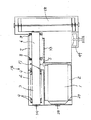
【図2】 コンバインの側面図。
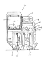
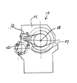
【図3】 脱穀装置の正面図。
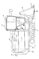
【図4】 脱穀装置の一部破断した側面図。
【図5】 脱穀装置の平断面図。
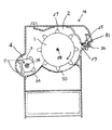
【図6】 脱穀装置の側面図。
【図7】 脱穀装置の一部切除した平断面図。
【図8】 処理歯の斜視図。
【図9】 処理歯の側面図。
【符号の説明】
1 扱胴
2 扱室
3 二番処理胴
4 二番処理室
5 扱室送塵口
6 排塵胴
7 排塵処理室
8 処理歯
9 処理歯
26 選別室
27 穀稈扱ぎ口
30 扱室受網
32 排塵口
33 排塵処理室受網
34 軸
35 二番物排出口
36 二番処理室受網
37 螺旋
38 取付け面
39 孔
40 縁部
54 二番還元装置
60 ギヤボックス
61 扱室前壁(扱室の前壁)
62 二番処理室側壁(二番処理室の側壁)[0001]
BACKGROUND OF THE INVENTION
The present invention relates to a threshing apparatus that can be used for a combine, a harvester, or the like.
[0002]
[Prior art]
A treatment chamber, a second treatment chamber, and a dust removal chamber are arranged side by side, and a treatment cylinder having tooth treatment provided in the treatment chamber, a second treatment cylinder having treatment teeth provided in the second treatment chamber, and a dust removal chamber are provided. Further, a threshing device having a configuration in which processing is performed by a dust removing cylinder having processing teeth substantially the same height as the second processing teeth has been considered.
[0003]
[Problems to be solved by the invention]
In such a configuration, the tip portion of the grain pod with a spike is threshed by the handling cylinder in the handling chamber, and the processed material that is not sufficiently processed in the handling chamber is treated by the dust collecting cylinder of the dust removal chamber and reduced. Since the second processing cylinder is processed by the second processing cylinder in the second processing chamber, a rational processing operation can be performed, but if the processing teeth of the second processing cylinder are high, it will be mixed into the reduced second object. It is easy to generate damage to the grain to do.
[0004]
[Means for Solving the Problems]
This invention provides the threshing apparatus which solves such a subject, and took the following technical means.
That is, the cereal supply port is formed in the front wall of the handling chamber (2) in which the handling cylinder (1) is rotatably provided, and the cereal discharge port is formed in the rear wall of the handling chamber (2). A handling chamber dust supply port (5) is provided on the opposite side of the grain haul handling port (27) at the terminal end of (2), and a dust exhaust cylinder (6) is provided to the handling chamber dust supply port (5). A dust exhaust port (32) communicating with the sorting chamber (26) is provided at the terminal end of the dust exhaust treatment chamber (7), and the dust exhaust chamber (7) is provided. In providing the spiral (37) in the part facing the handling chamber dust feed port (5) in 6) and providing a large number of treated teeth (8) on the rear side of the spiral (37), each treated tooth (8) Are formed in a U shape in which the left and right ends are bent upward, and the edge of each processing tooth (8) is formed in an arcuate curved surface, and a hole is formed in the mounting surface (38) of each processing tooth (8). (39 ) The end located direction of rotation side of Haichirido (6) of the edge of the mounting surface (38) (40) in the provided pores (39) inside (40) the Haichirido ( 6) welded to the dust disposal chamber (7), and has a mesh larger than the mesh of the handling chamber mesh (30) along the rotation path of the dust exhaust cylinder (6) in the dust disposal chamber (7). (33), and the shaft (34) on which the dust removal cylinder (6) is provided extends to the second processing chamber (4) adjacent to the handling chamber (2), and the shaft (34) allows the second When the second processing cylinder (3) is installed in the processing chamber (4) and a plurality of processing teeth (9) are provided in the second processing cylinder (3), the left and right ends of each processing tooth (9) And a processing tooth (9) which is bent into a U-shape and whose edges are formed in an arcuate curved surface and which is lower than the height of the processing tooth (8) of the dust removal cylinder (6). 9 ) And a hole (39) is provided in the mounting surface (38) of each processing tooth (9), and the second processing cylinder of the edge (40) of the mounting surface (38) in the hole (39). mounting by welding edges located on direction of rotation side (3) and (40) to the double-dip process cylinder (3), the dust-exhaust processing chamber received along the rotational locus of the double-dip process cylinder (3) A second processing chamber receiving net (36) having a mesh smaller than that of the net (33) is provided, and the transfer terminal end of the second reduction device (54) is placed above the start end of the second processing chamber (4). A second discharge port (35) communicating with the sorting chamber (26) is provided on the opposite side of the second processing chamber (4) from the dust processing chamber (7) in the second processing chamber (4). 6) and the gear box (60) for driving the second processing cylinder (3) span the front wall (61) of the handling chamber (2) and the side wall (62) of the second processing chamber (4). That Te attached to threshing apparatus according to claim.
[0005]
Grains threshed in the
[0006]
【The invention's effect】
Since the height of the
Furthermore, the
Further, since the
[0007]
DETAILED DESCRIPTION OF THE INVENTION
Hereinafter, an embodiment of the present invention will be described with reference to the drawings.
First, the configuration will be described. The
[0008]
The cutting and conveying
[0009]
The
[0010]
The
[0011]
The dust
[0012]
The
Further, in the embodiment, the
[0013]
The sorting
[0014]
The
57 is a cerealing device in which the cerealing end portion is communicated with the conveying end portion of the first
[0015]
The
Next, the operation will be described.
[0016]
First, when the driver sits on the seat of the combine driving section, depresses the parking brake pedal, puts the key into the key switch and starts the engine, the power output from the engine is transmitted to the rotating parts of the aircraft via the transmission mechanism. It is transmitted to. Then, the throttle lever is rotated to select the engine at a predetermined number of revolutions, the auxiliary transmission lever is rotated to a desired position, for example, the standard is selected, and the threshing lever and the cutting lever are operated. After driving the rotating parts of the machine and completing the preparation for the harvesting work, release the parking brake pedal, and then turn the shift lever to the side to move the machine forward and move the operating lever back and forth. Tilt to determine the height position of the cutting and conveying apparatus, or tilt to the left and right to change the traveling direction of the aircraft and align the weed body in a predetermined length.
[0017]
Then, the root portion of the cereal that is caused by the
[0018]
Many grains including small straw scraps generated thereby leak from the handling
[0019]
On the other hand, the threshing that has not leaked is sent to the end of the
[0020]
Then, a processed material containing a lot of straw waste that has not leaked from the dust collection
[0021]
In the sorting operation, the second product collected by the second
[0022]
The second object is sent to the opposite side of the dust
[0023]
Since the height of the
[0024]
Since the
Since the
[Brief description of the drawings]
FIG. 1 is a front view of a combine.
FIG. 2 is a side view of a combine.
FIG. 3 is a front view of a threshing apparatus.
FIG. 4 is a partially broken side view of a threshing apparatus.
FIG. 5 is a cross-sectional plan view of a threshing apparatus.
FIG. 6 is a side view of a threshing apparatus.
FIG. 7 is a cross-sectional plan view of the threshing device partially cut away.
FIG. 8 is a perspective view of a treated tooth.
FIG. 9 is a side view of a treated tooth.
[Explanation of symbols]
DESCRIPTION OF SYMBOLS 1
62 Side wall of second processing chamber (side wall of second processing chamber)
Claims (1)
Priority Applications (1)
| Application Number | Priority Date | Filing Date | Title |
|---|---|---|---|
| JP22937997A JP3775005B2 (en) | 1997-08-26 | 1997-08-26 | Threshing device |
Applications Claiming Priority (1)
| Application Number | Priority Date | Filing Date | Title |
|---|---|---|---|
| JP22937997A JP3775005B2 (en) | 1997-08-26 | 1997-08-26 | Threshing device |
Publications (2)
| Publication Number | Publication Date |
|---|---|
| JPH1156085A JPH1156085A (en) | 1999-03-02 |
| JP3775005B2 true JP3775005B2 (en) | 2006-05-17 |
Family
ID=16891262
Family Applications (1)
| Application Number | Title | Priority Date | Filing Date |
|---|---|---|---|
| JP22937997A Expired - Fee Related JP3775005B2 (en) | 1997-08-26 | 1997-08-26 | Threshing device |
Country Status (1)
| Country | Link |
|---|---|
| JP (1) | JP3775005B2 (en) |
-
1997
- 1997-08-26 JP JP22937997A patent/JP3775005B2/en not_active Expired - Fee Related
Also Published As
| Publication number | Publication date |
|---|---|
| JPH1156085A (en) | 1999-03-02 |
Similar Documents
| Publication | Publication Date | Title |
|---|---|---|
| JP2011024461A (en) | Combine | |
| JP3775005B2 (en) | Threshing device | |
| JP2003325033A (en) | Re-thresh-treating device of threshing machine | |
| JP7056702B2 (en) | Threshing device | |
| JP2002136216A (en) | Threshing apparatus | |
| JP2004208573A (en) | Threshing controller for combine harvester | |
| JP2007174999A (en) | Discharged culm-treating structure of whole culm-charging type combine harvester | |
| JP4569193B2 (en) | Threshing device | |
| JP4096500B2 (en) | Threshing device | |
| JP2007319067A5 (en) | ||
| JP3787603B2 (en) | Combine threshing equipment | |
| JP4400056B2 (en) | Combine | |
| JP2007319067A (en) | Thresher | |
| JP4782260B2 (en) | General purpose combine | |
| JP3633067B2 (en) | Threshing device | |
| JPH0518A (en) | Normal type combine | |
| JP3412230B2 (en) | Threshing equipment | |
| JP2002034324A (en) | Combine harvester | |
| JP4427638B2 (en) | Combine thresher structure | |
| JP2001103833A (en) | Reduction treatment structure for general combine harvester | |
| JP4639900B2 (en) | Threshing device | |
| JP2004275096A (en) | Combine harvester | |
| JP2004208574A (en) | Threshing controller for combine harvester | |
| JP2008271788A (en) | Combine harvester | |
| JP2006067837A (en) | Threshing apparatus |
Legal Events
| Date | Code | Title | Description |
|---|---|---|---|
| A977 | Report on retrieval |
Free format text: JAPANESE INTERMEDIATE CODE: A971007 Effective date: 20050414 |
|
| A131 | Notification of reasons for refusal |
Free format text: JAPANESE INTERMEDIATE CODE: A131 Effective date: 20050517 |
|
| A521 | Written amendment |
Free format text: JAPANESE INTERMEDIATE CODE: A523 Effective date: 20050713 |
|
| A131 | Notification of reasons for refusal |
Free format text: JAPANESE INTERMEDIATE CODE: A131 Effective date: 20051011 |
|
| A521 | Written amendment |
Free format text: JAPANESE INTERMEDIATE CODE: A523 Effective date: 20051208 |
|
| TRDD | Decision of grant or rejection written | ||
| A01 | Written decision to grant a patent or to grant a registration (utility model) |
Free format text: JAPANESE INTERMEDIATE CODE: A01 Effective date: 20060131 |
|
| A61 | First payment of annual fees (during grant procedure) |
Free format text: JAPANESE INTERMEDIATE CODE: A61 Effective date: 20060213 |
|
| R150 | Certificate of patent or registration of utility model |
Free format text: JAPANESE INTERMEDIATE CODE: R150 |
|
| FPAY | Renewal fee payment (event date is renewal date of database) |
Free format text: PAYMENT UNTIL: 20090303 Year of fee payment: 3 |
|
| FPAY | Renewal fee payment (event date is renewal date of database) |
Free format text: PAYMENT UNTIL: 20120303 Year of fee payment: 6 |
|
| FPAY | Renewal fee payment (event date is renewal date of database) |
Free format text: PAYMENT UNTIL: 20150303 Year of fee payment: 9 |
|
| LAPS | Cancellation because of no payment of annual fees |