JP4096500B2 - Threshing device - Google Patents

Threshing device Download PDF

Info

Publication number
JP4096500B2
JP4096500B2 JP2000231792A JP2000231792A JP4096500B2 JP 4096500 B2 JP4096500 B2 JP 4096500B2 JP 2000231792 A JP2000231792 A JP 2000231792A JP 2000231792 A JP2000231792 A JP 2000231792A JP 4096500 B2 JP4096500 B2 JP 4096500B2
Authority
JP
Japan
Prior art keywords
sorting shelf
swing sorting
sub
shelf
sheave
Prior art date
Legal status (The legal status is an assumption and is not a legal conclusion. Google has not performed a legal analysis and makes no representation as to the accuracy of the status listed.)
Expired - Fee Related
Application number
JP2000231792A
Other languages
Japanese (ja)
Other versions
JP2002045022A5 (en
JP2002045022A (en
Inventor
英一 今村
賢一朗 竹内
正実 松井
智之 市丸
Current Assignee (The listed assignees may be inaccurate. Google has not performed a legal analysis and makes no representation or warranty as to the accuracy of the list.)
Iseki and Co Ltd
Original Assignee
Iseki and Co Ltd
Priority date (The priority date is an assumption and is not a legal conclusion. Google has not performed a legal analysis and makes no representation as to the accuracy of the date listed.)
Filing date
Publication date
Application filed by Iseki and Co Ltd filed Critical Iseki and Co Ltd
Priority to JP2000231792A priority Critical patent/JP4096500B2/en
Publication of JP2002045022A publication Critical patent/JP2002045022A/en
Publication of JP2002045022A5 publication Critical patent/JP2002045022A5/ja
Application granted granted Critical
Publication of JP4096500B2 publication Critical patent/JP4096500B2/en
Anticipated expiration legal-status Critical
Expired - Fee Related legal-status Critical Current

Links

Images

Landscapes

  • Threshing Machine Elements (AREA)

Description

【0001】
【発明の属する技術分野】
この発明は、コンバインやハーベスタ等の脱穀装置に関するものである。
【0002】
【従来の技術】
従来の脱穀装置において、扱室の下方には揺動選別棚のみを設ける構成であった。
【0003】
【発明が解決しようとする課題】
前述のような脱穀装置では、次のような欠点がある。即ち、扱室内の被処理物量が多くなると、揺動選別棚に落下する被選別物量が多くなってしまい、選別性能の低下という不具合を生じていた。最悪の場合、揺動選別棚やその伝動系の破損が発生していた。
【0004】
本発明の課題は、前述のような不具合を防止する脱穀装置を提供することである。
【0005】
【課題を解決するための手段】
本発明の上記課題は次の構成によって達成される。
すなわち、請求項1記載の発明では、扱胴(1)を有する扱室(2)の下方に揺動選別棚(3)を設けた脱穀装置(4)において、前記揺動選別棚(3)は、被選別物の移送方向の上手側から移送棚(3a)と脱穀物を選別するグレンシーブ(3b)と二番物を選別するチャフシーブ(3c)と排塵を機外に移送して放出するストローラック(3d)とから構成し、揺動選別棚(3)の上部に、扱室(2)終端部の排出口(6)から落下する被選別物を受けて後方へ移送しながら選別する副揺動選別棚(5)を設け、該副揺動選別棚(5)は、前記扱室(2)の後部から脱穀装置(4)後部に設けている横断流ファン(7)の始端部近傍に配置して設け、副揺動選別棚(5)は、被選別物の移送方向の上手側から副移送棚(5a)と副シーブ(5b)と副ストローラック(5c)とを配置して構成し、副揺動選別棚(5)の副ストローラック(5c)と揺動選別棚(3)のストローラック(3d)は平面視においてそれぞれ交互に配置し、揺動選別棚(3)のグレンシーブ(3b)の間隔(l)に対して副揺動選別棚(5)の副シーブ(5b)の間隔(L)の方を長く構成し、副揺動選別棚(5)の副シーブ(5b)の終端部分(37)は、一番ラセン(24)の一番棚先(38)の終端部分(39)よりも後方に位置させる構成とし、さらに 、副揺動選別棚(5)の副ストローラック(5c)は、前側の回動支点(40)を支点として上下方向に振動するように構成したことを特徴とする脱穀装置としたものである。
【0006】
【0007】
【発明の実施の形態】
本発明の実施の形態を図面に基づいて説明する。
図1には、本発明の脱穀装置4を搭載したコンバインが示されている。走行装置8を有する車台9の前方には植立穀稈を刈り取る刈取装置10を設け、車台9上には前記刈取装置10で刈り取った穀稈をフィードチェン11にて挾持搬送しながら脱穀選別する脱穀装置4と、コンバインを操作する操作部12と、前記脱穀装置4にて脱穀選別した穀粒を一時貯溜するグレンタンク13とを設けている。
【0008】
また、グレンタンク13内下方には、一時貯溜している穀粒を機外へ排出する下部ラセン(図示せず)があり、該下部ラセンから搬送されてきた穀粒を引き継いでコンバインの機体上方へと搬送する縦オーガ14が車台9に対して旋回可能に設けられ、さらに、縦オーガ14には横オーガ15が昇降可能に設けられている。
【0009】
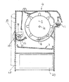
前記脱穀装置4について、図2〜図5に基づいて説明する。
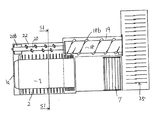
図2と図3は脱穀装置4の側面図、図4は脱穀装置4の平面図である。また、線の重なり防止のため、図2は二番処理胴20,排塵処理胴18等を省略していて、図3は副揺動選別棚5等を省略している。
【0010】
脱穀装置4内には、扱網16を有する扱胴1を扱胴軸1aで軸架した扱室2と、該扱室2の一側には、扱室2からの処理物を受け入れて処理する排塵処理網17を有する排塵処理胴18を排塵処理胴軸18aで軸架した排塵処理室19が設けられている。そして、扱室2と排塵処理室19の下方には揺動選別棚3を設けている。
【0011】
また、排塵処理胴18の前方には、二番処理胴20と二番処理胴受樋21(網や格子状のものでもよい。)からなる二番処理室22が構成されている。二番処理胴20は、本実施例では扱胴1の一側であって、排塵処理胴18の前方に設けられていて、基本的には二番物を処理するものである。さらに、図4は図3にて示すS1―S1断面であるが、扱網16から漏れた被処理物は二番処理室22内に取り込まれる構成であるので、前記二番処理胴20は二番物の他に、扱室2内から入り込んできた被処理物も一緒に処理する構成となっている。前記扱網16と二番処理胴受樋21(網や格子状でもよい)と排塵処理網17は、それぞれ扱胴1と二番処理胴20と排塵処理胴18の下方に設けられている。
【0012】
前記扱室2と二番処理室22と排塵処理室19の下方には、落下してくる被選別物を受けて選別する揺動選別棚3が設置されていて、該揺動選別棚3の下方には、選別風送り方向始端側に唐箕23を設け、該唐箕23から送風される選別風の送り方向下手側には一番ラセン24を設け、該一番ラセン24の選別風送り方向下手側には二番ラセン25を設けている。
【0013】
揺動選別棚3の構成について説明する。揺動選別棚3は、選別送り方向の始端側から順番に、落下した脱穀物を後方に移送する移送棚3a,脱穀物を選別するグレンシーブ3b,二番物を選別するチャフシーブ3c,排塵を機外に移送して放出するストローラック3dとから構成されている。該ストローラック3dの下方は、二番物を二番ラセン25内へ案内する二番棚先25aで構成されていて、この二番棚先25aの終端部近傍まで前記排塵処理胴18が延出している構成である。横断流ファン7は、選別室26内の軽い塵埃を機外に排出するためのもので、ストローラック3dの上方に設けられている。
【0014】
前述のごとく構成された脱穀装置4を搭載したコンバインにおいて、エンジン(図示せず)からの動力を走行伝動装置27に入力して、任意の速度に変速して走行装置8を駆動する。すると、コンバインは前進を開始する。刈取脱穀作業を行なうには、さらに、刈取装置10,供給搬送装置28及び脱穀装置4に、エンジンからの動力を伝達駆動して作業を行なう。このような状態でコンバインが前進すると、植立穀稈は分草具29により分草されて、引起しケース30の引起しラグ31にて引き起こされる。その後、刈刃32にて刈り取られ、刈り取られた穀稈は、株元搬送装置33により後方の供給搬送装置28の始端部に向かって搬送される。
【0015】
そして、株元搬送装置33の終端部まで搬送された穀稈は、後方の供給搬送装置28の始端部に引き継がれる。その後、供給搬送装置28の終端部まで搬送された穀稈は、脱穀装置4のフィードチェン11の始端部に引き継がれると共に、該フィードチェン11に引き継がれた穀稈は、後方に搬送されながら、扱胴1と扱網16により脱穀される。脱穀された脱穀物の一部は揺動選別棚3上に落下して、該揺動選別棚3の揺動作用と唐箕23からの風選作用により選別され、一番ラセン24内へと取り込まれていく。該一番ラセン24に取り込まれた穀粒は、グレンタンク13内に一時貯溜され、脱穀後の排稈はフィードチェン11の終端部から、排稈チェン34の始端部に引き継がれて搬送されていく。その後、カッター35に送られて切断されて、下方の圃場上に放出されていく。
【0016】
扱室2内の残りの脱穀物は、後方へと搬送されていくが、その途中において一部の脱穀物は二番処理室22内に取り込まれていく。該二番処理室22内に取り込まれた脱穀物は、選別風送り方向上手側に搬送されながら、二番処理胴20と二番処理胴受樋21との相互作用で脱穀(特に、枝梗粒が処理される)されて、下方の揺動選別棚3上に落下していく。扱胴1と二番処理胴20と排塵処理胴18は、共に選別風上手側から下手側を見た状況(脱穀装置4の正面視)において、時計回りで回転する構成であるので、従って、二番処理胴20の処理歯20aの向きは、脱穀物を選別風送り方向の上手側方向に送るような向きに固着しておく必要がある。
【0017】
即ち、該処理歯20aには被処理物を選別風送り方向上手側に搬送する作用があり、さらに、被処理物を処理する作用も併せ持っている。即ち、処理歯20aは螺旋の一部であり、また、その円周方向の先端部と二番処理胴受樋21との間の相互作用にて被処理物を処理する構成となっている。二番処理胴20の搬送終端部に設けられている羽根20bは、被処理物を揺動選別棚3上に強制的に送り出すようにする。
【0018】
前記排塵処理胴18の排塵処理歯18bは、脱穀物を選別風送り方向の下手側方向に送るような向きに固着しておく必要がある。本実施例では、該排塵処理歯18bは、排塵処理胴18の外周面に巻回いされているラセン形状となっている。
【0019】
しかし、本実施例では、排塵処理網17の目合いが荒い(格子状)ので、一部の短い藁屑は揺動選別棚3上に落下して、落下しなかった長い藁屑は排塵処理室19の終端部まで搬送されて、排塵処理胴18の終端部の羽根36にてストローラック3d上に強制的に排出される。そして、このように被処理物が排塵処理室19内にて搬送される間に、排塵処理胴18と排塵処理網17との相互作用で、さらに脱穀されるとともに、脱穀物はほぐされて中に混在している穀粒(いわゆるササリ粒)が取り出されて、下方の揺動選別棚3上に落下して、さらに、二番ラセン25内へと回収されていく。
【0020】
前述のように、扱室2内の脱穀物で、揺動選別棚3上に落下せず、二番処理室22内にも取り込まれなかった残りの脱穀物は、扱室1の終端部まで搬送される。この扱室1の終端部まで搬送されてきた脱穀物は、排塵処理室19内に取り込まれ、取り込まれた脱穀物は、選別風送り方向下手側に搬送されていく。
【0021】
扱室2内の終端部から排塵処理室19内に脱穀物を送る際において、脱穀物が詰まらないように、扱室2から排塵処理室19への引継ぎ部分においても、排塵処理胴18の外周にラセン形状の排塵処理歯18bを設けていて、該排塵処理歯18bの送り作用で引継ぎ部に脱穀物が詰まらないようにしている。
【0022】
このような、揺動選別棚3の揺動作用と唐箕23からの選別風の作用にもかかわらず、一番ラセン24内に取り込まれなかった残りの穀粒は、他の排塵物と共にさらに後方に送られ、二番ラセン25内へと取り込まれていく。該二番ラセン25内に取り込まれた二番物は、二番揚穀筒37にて前記二番処理室22の選別風送り方向下手側に還元されて、扱室2からの脱穀物と合流し、その後、選別風送り方向の上手側に搬送されながら、二番処理胴受樋21との相互作用で脱穀処理されながら搬送され、終端部の羽根20bにより下方の揺動選別棚3上に強制的に落下させられていく。
【0023】
このような一連の作業を行う脱穀装置4において、揺動選別棚3の上部には副揺動選別棚5を設ける構成とする。これにより、被選別物は揺動選別棚3と副揺動選別棚5の両方にて選別されるので、揺動選別棚3に作用する負荷が軽減するようになる。従って、穀粒の選別性能低下を防止できると共に、揺動選別棚3やその伝動系の破損も防止できる。
【0024】
また、副揺動選別棚5は、扱室2の後部から脱穀装置4後部に設けている横断流ファン7の始端部近傍に配置して設ける構成とする。扱室2後部の排出口6から落下する被選別物は、副揺動選別棚5に受けられて後方へと移送されながら選別され、該副揺動選別棚5の終端部まで搬送されてきた被選別物は横断流ファン7にて機外へと排出されていく。また、比重の重い被選別物は、下方の揺動選別棚3のストローラック3dへと落下していく。
【0025】
これにより、揺動選別棚3に作用する負荷が軽減するようになる。特に、扱室2終端部の排出口6から落下してくる被選別物を効率よく選別することができる。
さらに、副揺動選別棚5は、上手側から副移送棚5a,副シーブ5b,副ストローラック5cとから構成する。
【0026】
副揺動選別棚5の始端部に落下した被選別物は、副移送棚5aにて後方へと搬送され副シーブ5bへと送られる。該副シーブ5bへ送られた被選別物は揺動作用と唐箕23からの選別風により選別され、穀粒は下方へと落下する。残りの被選別物は、さらに後方の副ストローラック5cへと搬送され、揺動作用と選別風との作用により、ササリ粒が分けられてササリ粒は下方へと落下して、二番ラセン25内へと回収されていく。
【0027】
これにより、扱室2の終端部から落下してきた被選別物の選別性能が向上するようになると共に、揺動選別棚3に作用する負荷を軽減することができる。また、ササリ粒の回収効率も向上するようになる。
前記副揺動選別棚5の副シーブ5bの終端部分37は、一番棚先38の終端部分39よりも後方に位置するように構成する。これにより、副シーブ5bにて選別された穀粒は、一番ラセン24内へと効率的に回収できるようになる。
【0028】
副揺動選別棚5の副シーブ5bの間隔Lと、揺動選別棚3のグレンシーブ3bの間隔lとの関係においてL>lとなるように構成する。これにより、副揺動選別棚5の副シーブ5bにて選別された穀粒は、下方へと落下しやすくなる。また、小さな藁屑も下方へと落下しやすくなるので、副揺動選別棚5上に残るのは長い藁屑のみとなり、従って、副ストローラック5cでのササリ粒の回収が効率的に実行できるようになる。前記副シーブ5bから落下する小さな藁屑は、下方の揺動選別棚3にて選別されるので、問題はない。
【0029】
また、副揺動選別棚5の副ストローラック5cの終端部分と揺動選別棚3のストローラック3dの始端部分とは、所定距離Aオーバーラップするように構成する。すると、副ストローラック5c上の被選別物は、終端部まで搬送されて横断流ファン7に取り込まれなかったものは、下方のストローラック3d上に落下して再度ササリ粒が回収されるようになるので、ササリ粒の回収効率が向上するようになる。
【0030】
次に、図6について説明する。
副揺動選別棚5の副ストローラック5cは上下方向に振動するように構成する。具体的には、脱穀装置4の側方の機枠にピン38を固着し、該ピン38は、副ストローラック5cの取り付け部と共用の回動支点40に遊嵌して設けているプレート39の長穴39aに挿入している。
【0031】
これにより、副ストローラック5c上の被選別物のさばき作用が増大するので、ササリ粒の回収効率が向上するようになる。また、副ストローラック5cの終端部まで搬送されてきた藁屑は、横断流ファン7へと取り込まれやすくなり、藁屑の排出効率が向上するようになる。
【0032】
次に、図7について説明する。
前記副揺動選別棚5の副ストローラック5cと下方の揺動選別棚3のストローラック3dの位置関係において、それぞれを交互に配置する構成とする。これにより、上側の副ストローラック5cから藁屑が落下しても、下方のストローラック3dが受け止めるので、長い藁屑が二番ラセン25内に入り込むのを防止することができ、従って、結果的には一番ラセン24内の選別性能も向上するようになる。
【0033】
次に、図8について説明する。揺動選別棚3の駆動クランク軸40に遊嵌するカラー41を設け、該カラー41の左右にはプレート41aを延出し、さらに、該プレート41aには軸42を遊嵌している構成である。そして、該軸42にはゴム等の弾性体43を設けている。該弾性体43は、燃料タンク44に当接しているので、前記揺動選別棚3が駆動すると、弾性体43は燃料タンク44の上部を当接しながら前後方向に移動する。これにより、燃料タンク44上に藁屑等が堆積するのを防止することができる。
【0034】
【発明の効果】
請求項1記載の発明によると、被選別物は揺動選別棚3と副揺動選別棚5の両方にて選別されるので、揺動選別棚3に作用する負荷が軽減するようになる。従って、穀粒の選別性能低下を防止できると共に、揺動選別棚3やその伝動系の破損も防止できる。また、揺動選別棚3に作用する負荷が軽減するようになる。特に、扱室2終端部の排出口6から落下してくる被選別物を効率よく選別することができる。扱室2の終端部から落下してきた被選別物の選別性能が向上するようになると共に、揺動選別棚3に作用する負荷を軽減することができる。また、ササリ粒の回収効率も向上するようになる。
【0035】
また、副揺動選別棚5の副ストローラック5cと揺動選別棚3のストローラック3dは平面視においてそれぞれ交互に配置する構成としているので、上側の副ストローラック5cから藁屑が落下しても、下方のストローラック3dが受け止めるので、長い藁屑が揺動選別棚3のストローラック3d下方に落下していくのを防止することができるようになる。
また、揺動選別棚3のグレンシーブ3bの間隔lに対して副揺動選別棚5の副シーブ5bの間隔Lの方を長く構成しているので、副揺動選別棚5の副シーブ5bにて選別された穀粒は、下方へと落下しやすくなる。また、小さな藁屑も下方へと落下しやすくなるので、副揺動選別棚5上に残るのは長い藁屑のみとなり、従って、副ストローラック5cでの ササリ粒の回収、即ち、長い藁屑の中に存在する穀粒の回収が効率的に実行できるようになる。
また、副揺動選別棚5の副シーブ5bの終端部分37は、一番棚先38の終端部分39よりも後方に位置させる構成としているので、副シーブ5bにて選別された穀粒は、一番ラセン24内へと効率的に回収できるようになる。
また、副揺動選別棚5の副ストローラック5cは、前側の回動支点40を支点として上下方向に振動するように構成しているので、副ストローラック5c上の被選別物のさばき作用が増大してササリ粒の回収効率が向上するようになる。また、副ストローラック5cの終端部まで搬送されてきた藁屑は、横断流ファン7へと取り込まれやすくなり、藁屑の排出効率が向上するようになる。
【図面の簡単な説明】
【図1】コンバインの左側面図
【図2】脱穀装置の左側面図
【図3】脱穀装置の左側面図
【図4】脱穀装置の平面図
【図5】脱穀装置の正面の断面図
【図6】脱穀装置の左側面図
【図7】脱穀装置の平面図
【図8】背面図
【符号の説明】
1 扱胴
2 扱室
3 揺動選別棚
3a 移送棚
3b グレンシーブ
3c チャフシーブ
3d ストローラック
4 脱穀装置
5 副揺動選別棚
5a 副移送棚
5b 副シーブ
5c 副ストローラック
6 排出口
7 横断流ファン
24 一番ラセン
37 副シーブの終端部分
38 一番棚先
39 一番棚先の終端部分
40 副ストローラックの前側の回動支点
副揺動選別棚の副シーブの間隔
揺動選別棚のグレンシーブの間隔
[0001]
BACKGROUND OF THE INVENTION
The present invention relates to a threshing apparatus such as a combine or a harvester.
[0002]
[Prior art]
In a conventional threshing apparatus, only a swing sorting shelf is provided below the handling chamber.
[0003]
[Problems to be solved by the invention]
The threshing apparatus as described above has the following drawbacks. That is, when the amount of objects to be processed in the handling chamber increases, the amount of objects to be dropped on the swing sorting shelf increases, resulting in a problem that the sorting performance deteriorates. In the worst case, the swing sorting shelf and its transmission system were damaged.
[0004]
The subject of this invention is providing the threshing apparatus which prevents the above malfunctions.
[0005]
[Means for Solving the Problems]
The above object of the present invention is achieved by the following configuration.
That is, in invention of Claim 1, in the threshing apparatus (4) which provided the rocking | swiveling selection shelf (3) below the handling chamber (2) which has a handling cylinder (1), the said rocking | swiveling selection shelf (3) Transports and discharges dust from the transfer shelf (3a), grain sheave (3b) for sorting out cereals, chaff sheave (3c) for sorting second thing, and dust from the upper side in the direction of transfer of the objects to be sorted. It is composed of a Strolac (3d) and receives an object to be sorted falling from the discharge port (6) at the terminal end of the handling chamber (2) at the upper part of the swing sorting shelf (3) , and sorts it while moving it backward. A sub- oscillation sorting shelf (5) is provided , and the sub-oscillation sorting shelf (5) is a starting end portion of a cross flow fan (7) provided from the rear of the handling chamber (2) to the rear of the threshing device (4). The sub-oscillation sorting shelf (5) is arranged in the vicinity of the sub-transfer shelf (5a) from the upper side in the transfer direction of the object to be sorted. 5b) and a sub-straw back (5c) are arranged, and the sub-straw back (5c) of the sub-swing sorting shelf (5) and the stroll back (3d) of the swing sorting shelf (3) are in plan view. They are arranged alternately, and the interval (L) of the secondary sheave (5b) of the secondary swing sorting shelf (5) is longer than the interval (l) of the Glen sheave (3b) of the swing sorting shelf (3). The terminal portion (37) of the auxiliary sheave (5b) of the auxiliary swing sorting shelf (5) is positioned behind the terminal portion (39) of the first shelf tip (38) of the first spiral (24). configuration and then further sub straw rack FukuYurado sorting shelf (5) (5c) includes a threshing apparatus characterized by being configured to vibrate in a vertical direction forward of the pivot point (40) as a fulcrum It is a thing.
[0006]
[0007]
DETAILED DESCRIPTION OF THE INVENTION
Embodiments of the present invention will be described with reference to the drawings.
FIG. 1 shows a combine equipped with the threshing device 4 of the present invention. A reaping device 10 for harvesting planted cereals is provided in front of the chassis 9 having the traveling device 8, and threshing is performed on the chassis 9 while the stalks harvested by the reaping device 10 are held and conveyed by the feed chain 11. A threshing device 4, an operation unit 12 for operating a combine, and a grain tank 13 for temporarily storing grains threshed and sorted by the threshing device 4 are provided.
[0008]
A lower spiral (not shown) for discharging the temporarily stored grain to the outside of the machine is located below the Glen tank 13, and the grain conveyed from the lower spiral is taken over to the upper part of the combine body. A vertical auger 14 to be conveyed to the chassis 9 is provided so as to be rotatable with respect to the chassis 9, and a horizontal auger 15 is provided on the vertical auger 14 so as to be movable up and down.
[0009]
The said threshing apparatus 4 is demonstrated based on FIGS.
2 and FIG. 3 are side views of the threshing device 4, and FIG. 4 is a plan view of the threshing device 4. Further, in order to prevent the lines from overlapping, FIG. 2 omits the second processing cylinder 20, the dust removal processing cylinder 18 and the like, and FIG. 3 omits the auxiliary swing sorting shelf 5 and the like.
[0010]
In the threshing device 4, a handling chamber 2 in which a handling cylinder 1 having a handling net 16 is pivoted by a handling cylinder shaft 1 a and a treatment product from the handling chamber 2 are received and processed on one side of the handling chamber 2. A dust removal treatment chamber 19 is provided in which a dust removal treatment cylinder 18 having a dust removal treatment net 17 is mounted on a dust removal treatment cylinder shaft 18a. A swing sorting shelf 3 is provided below the handling chamber 2 and the dust removal processing chamber 19.
[0011]
Further, a second processing chamber 22 including a second processing cylinder 20 and a second processing cylinder receiving rod 21 (which may be a net or a lattice) may be formed in front of the dust removal processing cylinder 18. In this embodiment, the second processing cylinder 20 is provided on one side of the handling cylinder 1 and in front of the dust processing cylinder 18 and basically processes the second object. Further, FIG. 4 is a S1-S1 cross section shown in FIG. 3. Since the workpiece leaked from the handling net 16 is taken into the second processing chamber 22, the second processing cylinder 20 has two parts. In addition to the items, the workpieces that have entered from the handling chamber 2 are also processed together. The handling net 16, the second treatment cylinder receiving rod 21 (which may be a net or a lattice), and the dust treatment net 17 are provided below the treatment cylinder 1, the second treatment cylinder 20, and the dust treatment cylinder 18, respectively. Yes.
[0012]
Below the handling chamber 2, the second processing chamber 22, and the dust removal processing chamber 19, a swing sorting shelf 3 for receiving and sorting falling objects to be sorted is installed. Is provided with a red pepper 23 on the start side of the sorting air feed direction, and a first spiral 24 is provided on the lower side of the feeding direction of the sorting air blown from the red pepper 23. A second spiral 25 is provided on the lower side.
[0013]
The configuration of the swing sorting shelf 3 will be described. The swing sorting shelf 3 includes a transfer shelf 3a for transferring the fallen cereals backward, a grain sheave 3b for sorting the cereals, a chaff sheave 3c for sorting the second thing, and dust from the start side in the sorting feed direction. It is composed of a Strollac 3d that is transferred to the outside of the machine and discharged. Below the Strollac 3d is constituted by a second shelf tip 25a for guiding the second item into the second spiral 25, and the dust exhausting cylinder 18 extends to the vicinity of the terminal end of the second shelf tip 25a. It is the composition which has taken out. The cross flow fan 7 is for discharging light dust in the sorting chamber 26 to the outside of the machine, and is provided above the stroller 3d.
[0014]
In the combine equipped with the threshing device 4 configured as described above, the power from the engine (not shown) is input to the traveling transmission device 27, and the traveling device 8 is driven by shifting to an arbitrary speed. Then, the combine begins to move forward. In order to perform the reaping and threshing operation, the reaping device 10, the feeding and conveying device 28, and the threshing device 4 are further driven by transmitting power from the engine. When the combine advances in such a state, the planted cereal is weeded by the weeding tool 29 and is raised by the raising lug 31 of the case 30. Thereafter, the cereals harvested by the cutting blade 32 are transported toward the starting end of the rear supply transport device 28 by the stock transport device 33.
[0015]
Then, the cereal that has been transported to the terminal end of the stock transport device 33 is taken over by the starting end of the rear supply transport device 28. Thereafter, the cereals that have been transported to the terminal end of the supply and transport device 28 are handed over to the starting end of the feed chain 11 of the threshing device 4, and the cereals that have been handed over to the feed chain 11 are being transported backwards, Threshing is performed by the handling cylinder 1 and the handling net 16. A part of the threshed threshing falls on the swing sorting shelf 3 and is sorted by the swinging action of the swing sorting shelf 3 and the wind sorting action from the Kara 23 and taken into the first spiral 24. It will be. The grain taken into the first helix 24 is temporarily stored in the Glen tank 13, and the waste after threshing is transferred from the end of the feed chain 11 to the start of the waste chain 34 and conveyed. Go. Then, it is sent to the cutter 35, cut, and discharged onto the lower farm field.
[0016]
The remaining threshing in the handling chamber 2 is conveyed rearward, and part of the threshing is taken into the second processing chamber 22 in the middle of the process. The threshing taken into the second processing chamber 22 is threshed by the interaction between the second processing cylinder 20 and the second processing cylinder receiver 21 (particularly, branch branch) The particles are processed) and fall onto the lower swing sorting shelf 3. The handling cylinder 1, the second processing cylinder 20 and the dust removal processing cylinder 18 are all configured to rotate clockwise in a situation where the lower side is viewed from the sorting windward side (front view of the threshing device 4). The direction of the processing teeth 20a of the second processing cylinder 20 needs to be fixed in such a direction as to send the cereals in the upper direction of the sorting wind feed direction.
[0017]
That is, the processing tooth 20a has an action of conveying the object to be processed to the upper side in the sorting wind feed direction, and further has an action of processing the object to be processed. That is, the processing tooth 20a is a part of a spiral, and is configured to process the object to be processed by the interaction between the circumferential tip portion thereof and the second processing cylinder receiving rod 21. The blades 20b provided at the conveying terminal end of the second processing cylinder 20 force the object to be processed onto the swing sorting shelf 3.
[0018]
The dust removal processing teeth 18b of the dust removal processing cylinder 18 need to be fixed in such a direction as to send the cereals in the lower direction of the sorting wind feed direction. In the present embodiment, the dust removal treatment teeth 18 b have a spiral shape that is wound around the outer peripheral surface of the dust removal treatment cylinder 18.
[0019]
However, in this embodiment, the dust disposal net 17 is rough (lattice), so that some of the short sawdust falls on the swing sorting shelf 3 and the long sawdust that has not fallen is discarded. It is conveyed to the end portion of the dust treatment chamber 19 and is forcibly discharged onto the stroller 3d by the blades 36 at the end portion of the dust treatment cylinder 18. While the object to be treated is transported in the dust treatment chamber 19 as described above, the threshing is further loosened due to the interaction between the dust treatment cylinder 18 and the dust treatment net 17 and the threshing. Then, the grains (so-called scorpion grains) mixed in are taken out, fall on the lower swing sorting shelf 3, and further collected into the second spiral 25.
[0020]
As described above, the remaining threshing that has not fallen on the swing sorting shelf 3 and has not been taken into the second processing chamber 22 due to cerealing in the processing chamber 2 reaches the end of the processing chamber 1. Be transported. The threshing that has been transported to the end portion of the handling chamber 1 is taken into the dust removal processing chamber 19 and the taken threshing is transported to the lower side in the sorting wind feed direction.
[0021]
In order to prevent clogging of the cereal when the cereal is sent from the end portion in the processing chamber 2 into the dust processing chamber 19, the dust processing cylinder is also used in the handed over portion from the processing chamber 2 to the dust processing chamber 19. Spiral-shaped dust-removing treatment teeth 18b are provided on the outer periphery of 18 so that the cereals are not clogged in the takeover portion by the feeding action of the dust-removing treatment teeth 18b.
[0022]
Despite the rocking action of the rocking sorting shelf 3 and the action of the sorting wind from the tang 23, the remaining grains that are not taken into the spiral 24 together with other dusts are further removed. It is sent back and taken into the second spiral 25. The second product taken into the second helix 25 is reduced to the lower side in the sorting wind feed direction of the second processing chamber 22 by the second lifting cylinder 37 and merged with the cereal from the handling chamber 2. Then, while being transported to the upper side of the sorting wind feed direction, it is transported while being threshed by the interaction with the second processing cylinder receiving rod 21, and is placed on the lower swing sorting shelf 3 by the blade 20b at the end portion. It is forcibly dropped.
[0023]
In the threshing device 4 that performs such a series of operations, the sub-oscillation sorting shelf 5 is provided above the swing sorting shelf 3. As a result, the objects to be sorted are sorted by both the swing sorting shelf 3 and the sub-swing sorting shelf 5, so that the load acting on the swing sorting shelf 3 is reduced. Accordingly, it is possible to prevent the grain sorting performance from being lowered and to prevent the swing sorting shelf 3 and its transmission system from being damaged.
[0024]
Further, the auxiliary swing sorting shelf 5 is arranged to be provided in the vicinity of the start end portion of the cross flow fan 7 provided from the rear portion of the handling chamber 2 to the rear portion of the threshing device 4. The objects to be sorted that fall from the discharge port 6 at the rear of the handling chamber 2 are received by the secondary swing sorting shelf 5 and sorted while being transferred to the rear, and have been transported to the terminal end of the secondary swing sorting shelf 5. The objects to be sorted are discharged to the outside by the cross flow fan 7. In addition, the object to be sorted having a high specific gravity falls to the Strollac 3d of the swinging sorting shelf 3 below.
[0025]
As a result, the load acting on the swing sorting shelf 3 is reduced. In particular, it is possible to efficiently sort an object to be sorted that falls from the discharge port 6 at the end of the handling chamber 2.
Further, the secondary swing sorting shelf 5 includes a secondary transfer shelf 5a, a secondary sheave 5b, and a secondary stroller 5c from the upper side.
[0026]
The object to be sorted that has fallen to the starting end of the sub-oscillation sorting shelf 5 is conveyed rearward by the sub-transfer shelf 5a and sent to the sub-sheave 5b. The object to be sorted sent to the secondary sheave 5b is sorted by the swinging action and the sorting wind from the tang 23, and the grain falls downward. The remaining objects to be sorted are further transported to the rear sub-straw rack 5c, and the scorpion grains are separated by the action of the swinging action and the sorting wind, and the scorpion grains fall downward, and the second spiral 25 It will be collected inside.
[0027]
Thereby, the sorting performance of the object to be sorted that has fallen from the terminal portion of the handling chamber 2 is improved, and the load acting on the swing sorting shelf 3 can be reduced. Moreover, the recovery efficiency of scorpion grains is improved.
The end portion 37 of the sub sheave 5b of the sub-oscillation sorting shelf 5 is configured to be located behind the end portion 39 of the shelf tip 38. Thereby, the grain selected by the secondary sheave 5b can be most efficiently recovered into the spiral 24.
[0028]
In the relationship between the interval L between the sub sheaves 5b of the sub-oscillation sorting shelf 5 and the interval l between the Glen sheaves 3b of the oscillation sorting shelf 3, L> l is established. Thereby, the grain selected by the secondary sheave 5b of the secondary swing sorting shelf 5 is likely to fall downward. Further, since small swarf easily falls downward, only the long swarf remains on the sub-oscillation sorting shelf 5 and, therefore, the recovery of scorpion grains in the sub-straw rack 5c can be executed efficiently. It becomes like this. There is no problem because small swarf falling from the sub-sheave 5b is sorted by the swing sorting shelf 3 below.
[0029]
Further, the terminal end portion of the sub-straw rack 5c of the sub-swing sorting shelf 5 and the start end portion of the stroll back 3d of the swing sorting shelf 3 are configured to overlap by a predetermined distance A. Then, the object to be sorted on the sub-straw rack 5c is transported to the end portion and not taken into the crossflow fan 7, so that it falls on the lower stroll rack 3d and the scorpion grains are collected again. As a result, the recovery efficiency of scorpion grains is improved.
[0030]
Next, FIG. 6 will be described.
The auxiliary stroller 5c of the auxiliary swing sorting shelf 5 is configured to vibrate in the vertical direction. Specifically, a pin 38 is fixed to a machine frame on the side of the threshing device 4, and the pin 38 is loosely fitted on a rotation fulcrum 40 shared with the attachment portion of the sub-straw rack 5c. Are inserted into the long holes 39a.
[0031]
As a result, the sorting action of the objects to be sorted on the sub-stroll rack 5c increases, so that the recovery efficiency of the scorpion grains is improved. In addition, the waste that has been transported to the end of the sub-stroller 5c is easily taken into the transverse flow fan 7, and the waste efficiency of the waste is improved.
[0032]
Next, FIG. 7 will be described.
In the positional relationship between the sub-straw back 5c of the sub-swing sorting shelf 5 and the stroll back 3d of the bottom swing sorting shelf 3, the two are alternately arranged. As a result, even if the sawdust falls from the upper sub-straw rack 5c, the lower stroll rack 3d receives it, so that long sawdust can be prevented from entering the second spiral 25. First, the sorting performance in the spiral 24 is improved.
[0033]
Next, FIG. 8 will be described. A collar 41 that is loosely fitted to the drive crankshaft 40 of the swing sorting shelf 3 is provided, a plate 41a is extended to the left and right of the collar 41, and a shaft 42 is loosely fitted to the plate 41a. . The shaft 42 is provided with an elastic body 43 such as rubber. Since the elastic body 43 is in contact with the fuel tank 44, when the swing sorting shelf 3 is driven, the elastic body 43 moves in the front-rear direction while contacting the upper portion of the fuel tank 44. Thereby, it is possible to prevent soot and the like from accumulating on the fuel tank 44.
[0034]
【The invention's effect】
According to the first aspect of the present invention, since the objects to be sorted are sorted by both the swing sorting shelf 3 and the sub swing sorting shelf 5, the load acting on the swing sorting shelf 3 is reduced. Accordingly, it is possible to prevent the grain sorting performance from being lowered and to prevent the swing sorting shelf 3 and its transmission system from being damaged. Further, the load acting on the swing sorting shelf 3 is reduced. In particular, it is possible to efficiently sort an object to be sorted that falls from the discharge port 6 at the end of the handling chamber 2. The sorting performance of the sorting object falling from the terminal end of the handling chamber 2 is improved, and the load acting on the swing sorting shelf 3 can be reduced. Moreover, the recovery efficiency of scorpion grains is improved.
[0035]
Further, since the sub-straw back 5c of the sub-swinging sorting shelf 5 and the stroll back 3d of the swinging sorting shelf 3 are alternately arranged in a plan view, soot is dropped from the upper sub-straw back 5c. However, since the lower Strollac 3d receives it, it is possible to prevent the long sawdust from dropping below the Strollack 3d of the swing sorting shelf 3.
Further, since the interval L of the sub sheave 5b of the sub-oscillation sorting shelf 5 is longer than the interval l of the Glen sheave 3b of the oscillation sorting shelf 3, the sub sheave 5b of the sub-oscillation sorting shelf 5 is Thus, the selected grain tends to fall downward. In addition, since small swarf easily falls downward, only the long swarf remains on the secondary swing sorting shelf 5, and therefore, the recovery of the scorpion grains in the secondary stroller 5c, that is, the long swarf is left. The recovery of the grains existing in the rice can be carried out efficiently.
In addition, since the end portion 37 of the sub sheave 5b of the sub-oscillating sorting shelf 5 is positioned behind the end portion 39 of the first shelf tip 38, the grains selected by the sub sheave 5b are: The most efficient recovery into the spiral 24 is achieved.
Further, the sub-straw rack 5c of the sub-oscillation sorting shelf 5 is configured to vibrate in the vertical direction with the front rotation fulcrum 40 as a fulcrum, so that the object to be sorted on the sub-straw rack 5c is handled. Increases the efficiency of recovery of scorpion grains. In addition, the waste that has been transported to the end of the sub-stroller 5c is easily taken into the transverse flow fan 7, and the waste efficiency of the waste is improved.
[Brief description of the drawings]
[Fig. 1] Left side view of combine [Fig. 2] Left side view of threshing device [Fig. 3] Left side view of threshing device [Fig. 4] Plan view of threshing device [Fig. 5] Front sectional view of threshing device [Fig. [Fig. 6] Left side view of threshing device [Fig. 7] Top view of threshing device [Fig. 8] Rear view [Explanation of symbols]
1 Handling cylinder 2 Handling room 3 Swing sorting shelf
3a transfer shelf
3b Glen sieve
3c chaff sheave
3d straw rack 4 threshing apparatus 5 FukuYurado sorting shelves 5a secondary transfer shelf 5b secondary sheave 5c sub straw rack 6 outlet 7 cross flow fan
24 most spiral
37 Sub sheave end
38 first shelf
39 Terminal end of the first shelf
40 Rotating fulcrum on the front side
The distance between the sub sheaves on the L sub-oscillating sorting shelf
l Grench sieve interval of swing sorting shelf

Claims (1)

扱胴(1)を有する扱室(2)の下方に揺動選別棚(3)を設けた脱穀装置(4)において、前記揺動選別棚(3)は、被選別物の移送方向の上手側から移送棚(3a)と脱穀物を選別するグレンシーブ(3b)と二番物を選別するチャフシーブ(3c)と排塵を機外に移送して放出するストローラック(3d)とから構成し、揺動選別棚(3)の上部に、扱室(2)終端部の排出口(6)から落下する被選別物を受けて後方へ移送しながら選別する副揺動選別棚(5)を設け、該副揺動選別棚(5)は、前記扱室(2)の後部から脱穀装置(4)後部に設けている横断流ファン(7)の始端部近傍に配置して設け、副揺動選別棚(5)は、被選別物の移送方向の上手側から副移送棚(5a)と副シーブ(5b)と副ストローラック(5c)とを配置して構成し、副揺動選別棚(5)の副ストローラック(5c)と揺動選別棚(3)のストローラック(3d)は平面視においてそれぞれ交互に配置し、揺動選別棚(3)のグレンシーブ(3b)の間隔(l)に対して副揺動選別棚(5)の副シーブ(5b)の間隔(L)の方を長く構成し、副揺動選別棚(5)の副シーブ(5b)の終端部分(37)は、一番ラセン(24)の一番棚先(38)の終端部分(39)よりも後方に位置させる構成とし、さらに、副揺動選別棚(5)の副ストローラック(5c)は、前側の回動支点(40)を支点として上下方向に振動するように構成したことを特徴とする脱穀装置。In the threshing apparatus (4) provided with the swing sorting shelf (3) below the handling chamber (2) having the handling cylinder (1), the swing sorting shelf (3) is a superior in the direction of transfer of the object to be sorted. It consists of a transfer shelf (3a) from the side, a grain sheave (3b) that sorts out cereals, a chaff sheave (3c) that sorts out the second thing, and a Strollac (3d) that transports and discharges dust to the outside. On the upper part of the swing sorting shelf (3) , there is provided a sub-swing sorting shelf (5) that receives the object to be sorted falling from the discharge port (6) at the end of the handling chamber (2) and sorts it while moving it backward. The secondary swing sorting shelf (5) is provided in the vicinity of the start end portion of the cross flow fan (7) provided from the rear part of the handling chamber (2) to the rear part of the threshing device (4). The sorting shelf (5) includes a sub-transfer shelf (5a), a sub-sheave (5b), and a sub-straw rack (5c) from the upper side in the transfer direction of the object to be sorted. The sub-straw back (5c) of the sub-swing sorting shelf (5) and the stroll back (3d) of the swing sorting shelf (3) are alternately arranged in plan view, and the swing sorting shelf The interval (L) of the auxiliary sheave (5b) of the auxiliary swing sorting shelf (5) is made longer than the interval (l) of the Glen sheave (3b) of (3), and the auxiliary swing sorting shelf (5) The end portion (37) of the secondary sheave (5b) is positioned rearward of the end portion (39) of the first shelf tip (38) of the first spiral (24). The threshing apparatus according to (5), wherein the auxiliary Strollac (5c) is configured to vibrate in the vertical direction with the front rotation fulcrum (40) as a fulcrum .
JP2000231792A 2000-07-31 2000-07-31 Threshing device Expired - Fee Related JP4096500B2 (en)

Priority Applications (1)

Application Number Priority Date Filing Date Title
JP2000231792A JP4096500B2 (en) 2000-07-31 2000-07-31 Threshing device

Applications Claiming Priority (1)

Application Number Priority Date Filing Date Title
JP2000231792A JP4096500B2 (en) 2000-07-31 2000-07-31 Threshing device

Publications (3)

Publication Number Publication Date
JP2002045022A JP2002045022A (en) 2002-02-12
JP2002045022A5 JP2002045022A5 (en) 2007-01-25
JP4096500B2 true JP4096500B2 (en) 2008-06-04

Family

ID=18724571

Family Applications (1)

Application Number Title Priority Date Filing Date
JP2000231792A Expired - Fee Related JP4096500B2 (en) 2000-07-31 2000-07-31 Threshing device

Country Status (1)

Country Link
JP (1) JP4096500B2 (en)

Families Citing this family (2)

* Cited by examiner, † Cited by third party
Publication number Priority date Publication date Assignee Title
JP2009027934A (en) * 2007-07-24 2009-02-12 Mitsubishi Agricult Mach Co Ltd Threshing and separating apparatus
RU179988U1 (en) * 2018-03-28 2018-05-30 Константин Васильевич Попов MOBILE GRAIN CLEANING DEVICE

Also Published As

Publication number Publication date
JP2002045022A (en) 2002-02-12

Similar Documents

Publication Publication Date Title
JP4096500B2 (en) Threshing device
JP2003325033A (en) Re-thresh-treating device of threshing machine
JP2010124719A (en) Combine harvester
JP2002136216A (en) Threshing apparatus
JP4730561B2 (en) Threshing device
JP2008178303A (en) Threshing apparatus for combine harvester
JP2008136399A (en) Thresher
JP4569193B2 (en) Threshing device
JP5109523B2 (en) Threshing device
JP2008048696A (en) Thresher
JP2007104956A (en) Threshing device
JP2005312354A (en) Thresher
JP4400056B2 (en) Combine
JP2004089109A (en) Combine harvester thresh controller
JP4009695B2 (en) Combine
JP2005328762A (en) Threshing apparatus
JP2006067837A (en) Threshing apparatus
JP2007029037A (en) Threshing apparatus
JP2007159487A (en) Thresher
JP2006204237A (en) Thresher
JP2002305949A (en) Thresher
JP2007228835A (en) Shaking and separating apparatus of thresher
JP2008271788A (en) Combine harvester
JP2008035782A (en) Threshing device
JP2007259710A (en) Threshing apparatus

Legal Events

Date Code Title Description
A621 Written request for application examination

Free format text: JAPANESE INTERMEDIATE CODE: A621

Effective date: 20060306

A521 Written amendment

Free format text: JAPANESE INTERMEDIATE CODE: A523

Effective date: 20061130

A977 Report on retrieval

Free format text: JAPANESE INTERMEDIATE CODE: A971007

Effective date: 20070214

A131 Notification of reasons for refusal

Free format text: JAPANESE INTERMEDIATE CODE: A131

Effective date: 20070828

A521 Written amendment

Free format text: JAPANESE INTERMEDIATE CODE: A523

Effective date: 20071029

TRDD Decision of grant or rejection written
A01 Written decision to grant a patent or to grant a registration (utility model)

Free format text: JAPANESE INTERMEDIATE CODE: A01

Effective date: 20080219

A61 First payment of annual fees (during grant procedure)

Free format text: JAPANESE INTERMEDIATE CODE: A61

Effective date: 20080303

R150 Certificate of patent or registration of utility model

Free format text: JAPANESE INTERMEDIATE CODE: R150

FPAY Renewal fee payment (event date is renewal date of database)

Free format text: PAYMENT UNTIL: 20110321

Year of fee payment: 3

FPAY Renewal fee payment (event date is renewal date of database)

Free format text: PAYMENT UNTIL: 20110321

Year of fee payment: 3

LAPS Cancellation because of no payment of annual fees