JP3771380B2 - Liquid suction device - Google Patents
Liquid suction device Download PDFInfo
- Publication number
- JP3771380B2 JP3771380B2 JP24448698A JP24448698A JP3771380B2 JP 3771380 B2 JP3771380 B2 JP 3771380B2 JP 24448698 A JP24448698 A JP 24448698A JP 24448698 A JP24448698 A JP 24448698A JP 3771380 B2 JP3771380 B2 JP 3771380B2
- Authority
- JP
- Japan
- Prior art keywords
- liquid
- liquid suction
- container
- holding portion
- drive source
- Prior art date
- Legal status (The legal status is an assumption and is not a legal conclusion. Google has not performed a legal analysis and makes no representation as to the accuracy of the status listed.)
- Expired - Fee Related
Links
Images


Description
【0001】
【発明の属する技術分野】
本発明は、容器開口を封止した栓体を貫通することができる液体吸引管によって容器内の液体を吸引する液体吸引装置に関するものであり、試料分析装置等における液体試料の採取用に好適利用できる。
【0002】
【従来の技術】
ゴムキャップなどの栓体により容器開口が封止された密閉容器から液体試料を吸引する際、先端を斜めにカットした針状の吸引管が用いられている。
【0003】
キャップ突き刺し時に吸引管にゴムカスが詰まらないようにするため、(a)特開平9−304400号公報記載のごとく吸引管の側周面に吸引用開口を設けたものが知られている。
【0004】
一方、キャップありの容器(密閉容器)に対してもキャップなしの容器(開放容器)に対しても問題なく動作するようにするため、(b)特許第2511549号公報記載のごとく開放容器用のプローブと密閉容器用のニードルとを備えたものが知られている。
【0005】
【発明が解決しようとする課題】
吸引管を上下移動させるとき、開放容器に対しては小さな力でよいが、密閉容器に対しては大きな力が必要となる。開放容器に対して大きな力を供与することは機構上の無駄を生じさせ、機敏性が損なわれ、容器の上下位置によっては吸引管が容器底にクラッシュし吸引管を傷めてしまうなどの動作上の問題も生じさせる。例えば、液体吸引管及びその大駆動源を1つのユニットとしてこのユニットを水平方向にも移動させようとすると、このユニットは大型で大重量であるため高速水平移動ができない、水平移動のための機構も大型になってしまうという具体的問題に直面する。
【0006】
本発明は、状況に応じて、具体的には密閉容器に対しても開放容器に対しても、液体吸引管に適切な力を供与することができる液体吸引装置を提供することを課題とする。
【0007】
【課題を解決するための手段】
本発明の液体吸引装置は、所定位置に配置される容器と、先端が鋭利形成され液体を吸引することができる液体吸引管と、液体吸引管を保持し上下方向に移動する第1の保持部と、第1の保持部を上下移動させるための力を提供する第1の駆動源と、第1の保持部と係合しこれを押圧し上下方向に移動する第2の保持部と、第1の保持部と係合しこれを押圧し上下方向に移動する第2の保持部と、第2の保持部を上下移動させるための力を提供する第2の駆動源と、上記これら手段を制御する制御手段と、を備え、制御手段は、栓体なしの容器に対しては第1の保持部を第2の保持部と係合させずに第1の駆動源の力によって上下移動させ、栓体ありの容器に対しては第1の保持部を第2の保持部と係合させて第2の駆動源の力によって上下移動させるよう制御することを特徴とする。
【0008】
採取すべき液体(例えば被検査サンプル液)を収容した容器が所定位置に配置されると、その容器に向かって液体吸引管が移動する。栓体なしの開放容器に対するときは第1の保持部は第2の保持部と係合しない。すなわち、第2の保持部は第1の保持部に接触しない。そこで、第1の駆動源の力によって第1の保持部を移動させて液体吸引管を移動させることができる。
【0009】
栓体ありの密閉容器に対するときは第1の保持部は第2の保持部と係合する。すなわち、第2の保持部は第1の保持部に接触する。そこで、第2の駆動源の力によって第2の保持部で第1の保持部を押圧し液体吸引管を移動させることができる。容器ごとに栓体の有無を認識しつつ自動動作させる場合には、栓体の有無を検知する栓体検知手段を備えることが好ましい。
【0010】
このようにして第1の駆動源は比較的小さな力を液体吸引管に提供し上下移動させ、第2の駆動源は栓体を貫通させるため比較的大きな力を液体吸引管に提供し上下移動させることができる。すなわち状況に応じて液体吸引管移動の際の駆動方式(提供する力の大きさ)を異ならせることができる。そして、機構上の無駄も解消でき、動作の高速性、信頼性も確保できる。
【0011】
【発明の実施の形態】
使用される液体吸引管は、強度、液面検知可能の点で金属製が好ましく、耐腐食性、耐摩耗性の点でステンレスパイプの外壁に窒化クロム(CrN)などの硬化皮膜のコーティング処理がなされていることが好ましい。
【0012】
液体吸引管で吸引する液体としては特に限定されないが、分析装置で分析すべき血漿などの血液サンプルはその一例である。液体吸引装置において採取すべき液体(例えば被検査サンプル液)を収容した容器は検体ラックに載置されて順次吸引管下方に搬送されて来るようにするのが分析処理の自動化の点で好ましい。
【0013】
本発明の液体吸引装置において、第1の駆動源の力により液体吸引管が容器に向かって移動したときに液体吸引管に上向きの外力が作用したことを検知する外力検知手段と、液体吸引管先端部分が液面に到達したことを検知する液面検知手段を備え、制御手段は、上記外力が検知されなかった場合、液面検知手段による液面検知情報又は外力検知手段による外力検知情報に基いて第1の駆動源を停止させ、上記外力が検知された場合、液面検知手段による液面検知情報に基いて第2の駆動源を停止させるよう制御することが好ましい。上記外力検知手段は前記栓体検知手段として機能させることができる。
【0014】
液体吸引管、第1の保持部、第1の駆動源、外力検知手段が水平移動可能な第1ユニットに備えられることが、液体吸引装置を使用する上でより好ましい。
【0015】
このようにして、開放容器の液面位置が容器ごとに異なっていても液面検知手段により第1駆動源を停止させ吸引管を停止させることができる。すなわち吸引管に付着する液体の量を最小限にすることができる。さらに、開放容器の底位置が容器ごとに異なっていても外力検知手段により第1駆動源を停止させ吸引管を停止させることができる。すなわち吸引管が容器底に当接して損傷を受けることを防止することができる。密閉容器に対しても液面検知手段により第2駆動源を停止させ吸引管を停止させることができる。
【0016】
本発明の液体吸引装置において、管先端に斜めカット面が形成され、その斜めカット面における管内壁端に鋭角エッジが生じないよう構成されてなる液体吸引管を用いることが好ましい。
【0017】
この場合、吸引管先端部分の管内壁端に鋭角なエッジがないので、その部分で栓体を切断しその切断された栓体の一部が開口側に入り込むということが起こらない。すなわち吸引管は詰まりにくい。
【0018】
液体吸引管の管先端の管内壁端に鋭角なエッジが生じないようにするため、管内壁端の全周に鋭角エッジ削除の処理を施してもよいが、鋭角エッジが生じうる半周部分のみに鋭角エッジ削除処理を施してもよい。
【0019】
【実施例】
第1図は本発明の液体吸引装置の一例の概略構成を示す。第2図は本発明の液体吸引装置の一例の具体的な構成を示す。この液体吸引装置は本実施例においては血液凝固測定装置に内蔵されている。第2図は血液凝固測定装置の左側面側から見た図であり、図において右側が装置前面で左側が装置内側である。複数のサンプル容器68を一列に並べて保持したサンプルラック66はサンプラ(不図示)によって図において紙面裏から表の方向に1容器分ずつ移送される。
【0020】
第1図に示すように、この液体吸引装置は第1ユニット10と第2ユニット11とから構成されている。第1ユニット10は液体吸引管であるピペット12を保持する第1保持部30及びその第1の保持部30を上下移動させるための駆動源43を備えている。第2ユニット11は第1の保持部30と係合する第2の保持部74及び第2の保持部74を上下移動させるための駆動源86を備えている。第1ユニット10は水平移動可能となっている。二点鎖線は第1ユニット10が最前に位置し、第1保持部30が第2保持部74に近接し両者が係合しうる状態を示す。実線は第1ユニット10が後方に位置し、第1保持部30は第2保持部74から離れ両者は係合し得ない状態を示す。
【0021】
ピペット12は内部通路14(図4参照)を有しており、外径2.0mm、内径1.3mm、全長約130mmのステンレス製の円筒管である。ピペット12の上端部には電線34が接続されている。電線34は液面検知回路35に接続され、ピペット先端が液面に接触する際の容量(キャパシタンス)変化に基づき液面を検知する。ピペット12上端にはチューブ36が接続されそのチューブ36はシリンジポンプなどの液体定量装置37に接続される。本実施例においては第1ユニットは駆動源94、96により水平方向に移動される。
【0022】
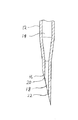
第3、4図はピペットの先端部分の部分拡大図、部分拡大断面図である。ピペット12は下端部付近において外径1.2mm、内径0.5mmに細く絞られ管軸に対して図のように斜めに鋭利カットされている。内部通路14は斜めカット面16に開口18する。単に斜めにカットしただけでは斜めカット面16における内壁端21に鋭角のエッジが発生する(上側の半周20には鋭角のエッジ、下側の半周22には鈍角のエッジが発生する)。
【0023】
第5図は従来のピペット13におけるゴムキャップ突き刺し状態を示している。内壁端に鋭角のエッジがあるので、ゴムキャップ突き刺し時に鋭角のエッジ23でゴムキャップ24を切断しその切断されたゴムキャップの一部(ゴムカス)が開口に進入するので、すぐに詰まりが発生する。
【0024】
そこで、上側の半周部分20について鋭角のエッジを除去する面取処理を施した。このことにより内壁端の全周について鋭角のエッジをなくすことができ、少なくとも3万回の連続試験においても詰まりが発生しないことが確認された。ピペット12は下端から約80mmまでの領域の外壁に耐摩耗性を高めるため窒化クロム(CrN)のコーティング処理が施されている。
【0025】
第2図は液体吸引装置の一実施例の一部切り欠き側面図である。44は第1ユニット10の第1シャーシである。40、41はプーリ、42はプーリ40、41に掛け渡されたベルトである。一方のプーリ41は第1の駆動源であるモータ43(本実施例ではステッピングモータ)の軸に直結している。ベルト42の一部に部材を取り付ければ第1のモータ43の回転によりその部材は上下移動することができる。
【0026】
第1ユニット10にはピペット12に上向きの外力が作用したときにこれを検知する外力検知手段54が備えられている。部材48を介してベルト42に取り付けられた部材50は第2シャーシ38に回転可能に支持されている。第2シャーシ38は第1シャーシ44に取り付けられたガイドシャフト46、47により上下移動のみできるようにガイドされている。第2シャーシ38にはピペット12を保持した第1保持部が取り付けられる。第2シャーシ38と部材50の間には圧縮コイルバネなどの付勢手段52が配置されている。
【0027】
ピペット12に外力が作用していない状態では部材50は第2シャーシ38に設けられた部材54を支点として図において時計方向に付勢され第2シャーシに設けられた係止部56に当接されている。よって、第1のモータ43の回転により第1保持部30、第2シャーシ38、部材50は一体化して上下移動する。
【0028】
もし、ピペット下降中にピペット12に物が当接し上向きの外力が作用すると、部材50の部材48側は下方に移動するが第2シャーシ38の支点54側は停止するので、部材50はバネ52の圧縮力に逆らって二点鎖線に示すように部材50は相対的に反時計周りに回転する。この微少な変動をマイクロスイッチなどのセンサ53により検出する。センサ53は電線により外力検知回路55に接続され、外力検知が行われる。
【0029】
58は貫通孔を備え上下移動するピペットのガイド手段として機能するガイド部材である。ガイド部材58は第1シャーシ44に取り付けられている。本実施例ではピペット12は100mm以上の長さを有するので移動時に水平方向のブレを発生させないようにするために設けられている。
【0030】
60は貫通孔63(図1参照)を備えその貫通孔63にポート62から洗浄液を供給しポート64から廃液を排出することによりピペット12壁を洗浄する洗浄部である。洗浄部60は部材70を介してエアーシリンダなどの駆動源72により上下移動される。71は垂直方向に設けられ部材70をガイドするガイドレールである。
【0031】
第2ユニットについて説明する。74は第1保持部30と係合しうる第2保持部である。本実施例では凹部と凸部の嵌まり合いにより両者30、74が連結されるように構成されている。第1保持部30には凸部32が設けられている。第2保持部74にはその凸部32が隙間を有して嵌まる凹部76が設けられている。凸部32の上下方向の幅は約6mm、凹部の上下方向の幅は14mmであり、第1保持部は第2保持部の干渉なしに移動できる余裕、すなわち8mmの不干渉範囲を有している。
【0032】
80は軸受84、85により回転自在に支持され螺旋溝を有するドライブシャフト、82はドライブシャフト80に螺合しドライブシャフト80の回転に伴い上下移動する移動子である。ドライブシャフト80の一端にプーリ89が取り付けられプーリ88、ベルト90を介して第2のモータ(ステッピングモータ)86の回転がドライブシャフト80に伝達される。第2保持部74は部材78を介してこの移動子82に取り付けられガイドレール71にガイドされて上下移動する。
【0033】
第1保持部30と第2保持部74が係合状態にあるときに第1のモータ43への電力供給をなくし第2のモータ86を回転させれば、第2の保持部74が第1の保持部30を押圧し移動させることができる。このとき第1のモータ43は外力により強制的に回転させられることになる。
【0034】
本実施例では第1ユニット10はモータ94により紙面左右方向に水平移動するよう構成されている。さらに、モータ96により紙面表裏方向にも水平移動するよう構成されている。第1ユニット10は装置前側(右側)にあるときに第1の保持部30と第2の保持部74とが係合するようになっている。第1ユニット10が後方(左側)に移動すれば両者の係合は解除され、ピペット12は専ら第1のモータ43の回転により上下移動する。
【0035】
本実施例ではサンプル液である血漿を収容したサンプル容器はサンプラにより例えば10本の容器を装着可能なサンプルラック66に装着されて搬送される。第6図はサンプルラック66を血液凝固測定装置の前面側から見たサンプルラックであり、サンプルラック66は右から左に1サンプル容器ずつ間欠的に移動され、順次ピペット下方に配置される。本実施例において使用されるサンプル容器は3種類に大別される。第1種はサンプルラック66底壁に載置された密閉容器a,b,c,d,e,f(容器底はサンプルラック底壁に当接している)。各容器はキャップが異なっている。第2種はサンプルラック底壁に載置された開放容器g(容器底はサンプルラック底壁に当接している)。第3種はサンプルラック底壁上方に載置した開放容器h,i,j(各容器はフランジを備え、サンプルラック上壁に当接h,jしたりや載置用開放容器上端に当接iしたりしている。いずれの開放容器も底はサンプルラック底壁には当接していない)。
【0036】
本実施例においては、洗浄部60の貫通孔63の下面にはテーパ部61を備えるのでfのような特異な容器(SARSTEDT社のMONOVETTEなる真空採血管)であっても位置ずれすることなく容器を保持することができる。
【0037】
制御部92はプログラムに従い、前記センサからの信号を受信し各モータを駆動させる。液体吸引装置の動作を説明する。
【0038】
<ステップ1:容器キャップの有無検知>
第1ユニット10が最前に位置した状態において、第1のモータ43及び第2のモータ86を回転させて第1保持部30及び第2保持部74を共に下降させることにより前記係合不干渉状態を維持しつつ、ピペット12を初期位置(最上点)から洗浄部60を貫通し所定距離下降させる。その間、制御部92は外力検知回路55からの信号を監視する。ピペット12に外力が作用したと検知されればキャップありの密閉容器であると判断し第1のモータ43を停止させる。ピペット12が所定距離下降しても外力が作用しなければキャップなしの開放容器であると判断する。
【0039】
<ステップ2−1:密閉容器の場合のピペットの下降(突き刺し)>
停止した第1のモータ43をごくわずか逆方向に回転させピペット12先端をキャップから離す。そして、駆動源72を駆動し洗浄部を下降させ洗浄部60下面で容器68のキャップ69を押圧保持する。第1のモータ43への電力供給をストップし、第2のモータ86を回転させる。第2の保持部74は第1の保持部30を押し下げることによりピペット12を容器68のキャップ69に突き刺す(ピペット12は専ら第2のモータ86の力により下降する)。そして、液面検知回路35からの液面検知情報、予め設定された最下点に到達したとの位置情報のいずれかの情報により第2のモータ86は停止させられピペット12も停止する。
【0040】
<ステップ2−2:開放容器の場合のピペットの下降>
継続して第1のモータ43及び第2のモータ86を回転させて、第1の保持部30を第2の保持部74に当接させることなく下降させる(ピペット12は第1のモータ43の力により下降する)。そして、液面検知回路35からの液面検知情報、外力検知回路55からの外力検知情報、予め設定された最下点に到達したとの位置情報のいずれかの情報により第1のモータ43は停止させられピペット12も停止する。
【0041】
<ステップ3:サンプル液吸引>
ピペット12を吸引量に応じて所定距離下降させ、液体定量装置37を動作させピペット12先端の開口18から血漿を所定量吸引する(5μlから500μlまで)。なお、上記ステップ2−1において最下点到達によりピペット12が下降停止した場合、ステップ2−2において外力検知又は最下点到達によりピペット12が下降停止した場合は吸引すべき血漿がないということであるので液の吸引は行わずサンプル液なしとのエラーメッセージを出力する。
【0042】
<ステップ4−1:密閉容器の場合のピペットの上昇(引き抜き)>
第1のモータ43への電力供給をストップしたまま第2のモータ86を逆回転させる。第2の保持部74が第1の保持部30を押し上げることによりピペット12を容器68のキャップ69から引き抜く(ピペット12は専ら第2のモータ86の力により上昇する)。同時に洗浄部60に洗浄液を供給し廃液を排出しピペット12外壁を洗浄する。引き抜きが完了すれば洗浄部60を上昇させ容器68の保持を解除する。ピペット12は初期位置に戻る。
【0043】
<ステップ4−2:開放容器の場合のピペットの上昇>
第1のモータ43、第2のモータ86を逆回転させて、第1の保持部30を第2の保持部74に当接させることなく上昇させる(ピペット12は専ら第1のモータ43の力により上昇する)。同時に洗浄部60に洗浄液を供給し廃液を排出しピペット12外壁を洗浄する。ピペット12は初期位置に戻る。
【0044】
<ステップ5:ピペットの後方移動>
モータ94を回転させ第1ユニット10を後方移動させる。このことにより第1の保持部は第2の保持部からの係合から完全に解除される。また必要に応じてモータ96を回転させ第1ユニットを横方向移動させてもよい。
【0045】
<ステップ6:ピペットの下降>
第1の保持部30は第2の保持部74の係合が解除されているので、第1のモータ43だけを回転させてピペット12を所定量下降させる。
【0046】
<ステップ7:サンプル液吐出>
液体定量装置37を動作させピペット12先端の開口18から反応容器(不図示)内に血漿を所定量吐出する。
【0047】
<ステップ8:ピペットの上昇>
第1のモータ43を逆回転させてピペット12を上昇させる。そしてピペット12の内外壁を洗浄する。例えばモータ94又はモータ96によってピペット12を図示しない洗浄容器へ移動し洗浄する。あるいはピペット12内部通路14に洗浄液を供給し洗浄部60に洗浄液を供給しこれら廃液を洗浄部60から排出しピペット12内外壁を洗浄してもよい。
【0048】
<ステップ9:ピペットの前方移動>
モータ94を逆回転させ第1ユニット10を前方移動させる。ピペット12は初期位置に戻る。第1の保持部は第2の保持部と係合しうる状態になる。
【0049】
【発明の効果】
本発明の液体吸引装置は、液体吸引管を保持する第1の保持部を第1の駆動源により上下移動させ、第1の保持部と係合することができる第2の保持部を第2の駆動源により上下移動させている。栓体なしの開放容器に対しては第1の保持部は第2の保持部と係合しないので第1の駆動源の力によって第1の保持部を移動させて液体吸引管を移動させることができる。栓体ありの密閉容器に対してはの場合、第1の保持部は第2の保持部と係合するので第2の駆動源の力によって第2の保持部で第1の保持部を押圧し液体吸引管を移動させることができる。このようにして状況に応じて液体吸引管の移動の際の駆動方式を異ならせることができる。そして、機構上の無駄を解消し、動作の高速性、信頼性も確保できる。
【図面の簡単な説明】
【図1】本発明における液体吸引装置の概略構成図である。
【図2】本発明における液体吸引装置の一部切り欠き側面図である。
【図3】液体吸引管の先端部分の側面図である。
【図4】液体吸引管の先端部分の側断面図である。
【図5】従来の液体吸引管におけるゴムキャップ突き刺し時側面図である。
【図6】各種サンプル容器が装着されたサンプルラックの正面図である。
【符号の説明】
10 第1ユニット
11 第2ユニット
12 液体吸引管(ピペット)
16 斜めカット面
20 管内壁端
30 第1の保持部
35 液面検知手段
37 液体定量装置
43 第1の駆動源(モータ)
54 外力検知手段
60 洗浄部
68 サンプル容器
74 第2の保持部
86 第2の駆動源(モータ)
92 制御部[0001]
BACKGROUND OF THE INVENTION
The present invention relates to a liquid suction device that sucks a liquid in a container by a liquid suction tube that can penetrate a stopper that seals the opening of the container, and is suitably used for collecting a liquid sample in a sample analyzer or the like. it can.
[0002]
[Prior art]
When a liquid sample is sucked from a sealed container whose container opening is sealed by a stopper such as a rubber cap, a needle-like suction tube whose tip is cut obliquely is used.
[0003]
In order to prevent rubber debris from being clogged in the suction pipe when the cap is pierced, there has been known (a) a suction pipe provided with a suction opening as described in JP-A-9-304400.
[0004]
On the other hand, in order to operate without problems for containers with caps (closed containers) and containers without caps (open containers), (b) as described in Japanese Patent No. 2511549, One having a probe and a needle for an airtight container is known.
[0005]
[Problems to be solved by the invention]
When the suction tube is moved up and down, a small force is required for the open container, but a large force is required for the sealed container. Giving a large force to the open container causes waste in the mechanism, impairs agility, and depending on the vertical position of the container, the suction pipe may crash at the bottom of the container and damage the suction pipe. This also causes problems. For example, when this unit is moved in the horizontal direction with the liquid suction pipe and its large drive source as one unit, this unit is large and heavy, and cannot move at high speed horizontally. Face the concrete problem of becoming too large.
[0006]
An object of the present invention is to provide a liquid suction device capable of supplying an appropriate force to a liquid suction pipe depending on the situation, specifically for a closed container and an open container. .
[0007]
[Means for Solving the Problems]
The liquid suction device according to the present invention includes a container disposed at a predetermined position, a liquid suction tube that has a sharp tip and can suck liquid, and a first holding unit that holds the liquid suction tube and moves in the vertical direction. A first drive source that provides a force for moving the first holding portion up and down, a second holding portion that engages with and presses the first holding portion and moves up and down, A second holding portion that engages with and holds the first holding portion and moves in the vertical direction; a second drive source that provides a force for moving the second holding portion up and down; and the above means Control means for controlling, and for the container without a stopper, the control means moves the first holding part up and down by the force of the first drive source without engaging the second holding part. For a container with a stopper, the first holding portion is engaged with the second holding portion, and the second drive source is used to move the container up and down. And controlling so as to dynamic.
[0008]
When a container containing a liquid to be collected (for example, a sample liquid to be inspected) is placed at a predetermined position, the liquid suction tube moves toward the container. The first holding part does not engage with the second holding part when the open container without a stopper is used. That is, the second holding unit does not contact the first holding unit. Therefore, the liquid suction tube can be moved by moving the first holding portion by the force of the first drive source.
[0009]
When the closed container with a stopper is used, the first holding part is engaged with the second holding part. That is, the second holding unit comes into contact with the first holding unit. Therefore, the liquid holding tube can be moved by pressing the first holding portion with the second holding portion by the force of the second drive source. When the automatic operation is performed while recognizing the presence or absence of a plug for each container, it is preferable to include a plug detection means for detecting the presence or absence of the plug.
[0010]
In this way, the first driving source provides a relatively small force to the liquid suction tube and moves up and down, and the second driving source provides a relatively large force to the liquid suction tube and moves up and down to penetrate the plug body. Can be made. That is, the driving method (the magnitude of the force to be provided) when moving the liquid suction tube can be varied depending on the situation. And the waste on the mechanism can be eliminated, and high speed and reliability of operation can be secured.
[0011]
DETAILED DESCRIPTION OF THE INVENTION
The liquid suction tube used is preferably made of metal in terms of strength and liquid level detection, and the outer wall of the stainless steel pipe is coated with a hard coating such as chromium nitride (CrN) in terms of corrosion resistance and wear resistance. It is preferable that it is made.
[0012]
Although it does not specifically limit as a liquid attracted | sucked with a liquid suction tube, The blood samples, such as plasma which should be analyzed with an analyzer, are the examples. It is preferable from the viewpoint of automation of analysis processing that the container containing the liquid to be collected (for example, sample liquid to be inspected) in the liquid suction device is placed on the sample rack and sequentially transported below the suction tube.
[0013]
In the liquid suction device of the present invention, an external force detecting means for detecting that an upward external force is applied to the liquid suction tube when the liquid suction tube moves toward the container by the force of the first drive source, and the liquid suction tube When the external force is not detected, the control means includes liquid level detection information by the liquid level detection means or external force detection information by the external force detection means when detecting that the external force is not detected. Based on the liquid level detection information by the liquid level detection means, it is preferable to control the second drive source to stop when the first driving source is stopped based on the detected external force. The external force detection means can function as the plug detection means.
[0014]
It is more preferable in using the liquid suction device that the liquid suction tube, the first holding unit, the first drive source, and the external force detection means are provided in the horizontally movable first unit.
[0015]
In this way, even if the liquid level position of the open container is different for each container, the first drive source can be stopped by the liquid level detection means and the suction pipe can be stopped. That is, the amount of liquid adhering to the suction tube can be minimized. Furthermore, even if the bottom position of the open container is different for each container, the first drive source can be stopped by the external force detection means to stop the suction pipe. That is, it is possible to prevent the suction tube from being in contact with the bottom of the container and being damaged. The second drive source can be stopped and the suction tube can be stopped by the liquid level detection means for the sealed container.
[0016]
In the liquid suction device of the present invention, it is preferable to use a liquid suction tube that is configured so that an oblique cut surface is formed at the distal end of the tube, and an acute edge is not generated at the inner wall end of the oblique cut surface.
[0017]
In this case, since there is no sharp edge at the end of the inner wall of the suction tube tip portion, the plug body is not cut at that portion and a part of the cut plug body does not enter the opening side. That is, the suction tube is not easily clogged.
[0018]
In order to prevent sharp edges from occurring at the inner wall end of the pipe tip of the liquid suction tube, the entire circumference of the inner wall edge may be subjected to the removal of acute angle edges, but only to the half-circumferential part where sharp edges can occur. An acute edge deletion process may be performed.
[0019]
【Example】
FIG. 1 shows a schematic configuration of an example of the liquid suction device of the present invention. FIG. 2 shows a specific configuration of an example of the liquid suction device of the present invention. This liquid suction device is built in the blood coagulation measuring device in this embodiment. FIG. 2 is a view as seen from the left side of the blood coagulation measuring apparatus, in which the right side is the front of the apparatus and the left side is the inside of the apparatus. A
[0020]
As shown in FIG. 1, the liquid suction device includes a
[0021]
The
[0022]
3 and 4 are a partially enlarged view and a partially enlarged sectional view of the tip portion of the pipette. The
[0023]
FIG. 5 shows a state where the
[0024]
Therefore, a chamfering process was performed on the upper half
[0025]
FIG. 2 is a partially cutaway side view of an embodiment of the liquid suction device.
[0026]
The
[0027]
When no external force is applied to the
[0028]
If an object comes into contact with the
[0029]
Reference numeral 58 denotes a guide member that functions as guide means for a pipette that has a through hole and moves up and down. The guide member 58 is attached to the
[0030]
A
[0031]
The second unit will be described.
[0032]
A
[0033]
When the
[0034]
In the present embodiment, the
[0035]
In this embodiment, a sample container containing plasma as a sample solution is mounted on a
[0036]
In this embodiment, since the tapered portion 61 is provided on the lower surface of the through-hole 63 of the
[0037]
The
[0038]
<Step 1: Detection of presence / absence of container cap>
In the state in which the
[0039]
<Step 2-1: Pipette lowering (piercing) in the case of a sealed container>
The stopped
[0040]
<Step 2-2: Lowering of pipette in case of open container>
The
[0041]
<Step 3: Sample suction>
The
[0042]
<Step 4-1: Ascending pipette (withdrawal) in closed container>
The
[0043]
<Step 4-2: Raising the pipette in the case of an open container>
The
[0044]
<Step 5: Backward movement of pipette>
The motor 94 is rotated to move the
[0045]
<Step 6: Lowering the pipette>
Since the
[0046]
<Step 7: Sample liquid discharge>
The
[0047]
<Step 8: Raising the pipette>
The
[0048]
<Step 9: Moving the pipette forward>
The motor 94 is reversely rotated to move the
[0049]
【The invention's effect】
In the liquid suction device of the present invention, the first holding unit that holds the liquid suction tube is moved up and down by the first drive source, and the second holding unit that can be engaged with the first holding unit is the second. It is moved up and down by the drive source. For an open container without a stopper, the first holding part does not engage with the second holding part, so that the first holding part is moved by the force of the first driving source to move the liquid suction tube. Can do. In the case of an airtight container with a stopper, the first holding part is engaged with the second holding part, so the second holding part presses the first holding part by the force of the second driving source. The liquid suction tube can be moved. In this way, the driving method for moving the liquid suction tube can be varied depending on the situation. And the waste on the mechanism can be eliminated, and the high speed and reliability of the operation can be secured.
[Brief description of the drawings]
FIG. 1 is a schematic configuration diagram of a liquid suction device according to the present invention.
FIG. 2 is a partially cutaway side view of the liquid suction device according to the present invention.
FIG. 3 is a side view of a tip portion of a liquid suction tube.
FIG. 4 is a side sectional view of a tip portion of a liquid suction tube.
FIG. 5 is a side view of a conventional liquid suction tube when a rubber cap is pierced.
FIG. 6 is a front view of a sample rack on which various sample containers are mounted.
[Explanation of symbols]
10 First unit 11
16
54 External force detection means 60
92 Control unit
Claims (3)
先端が鋭利形成され液体を吸引することができる液体吸引管と、
液体吸引管を保持し上下方向に移動する第1の保持部と、
第1の保持部を上下移動させるための力を提供する第1の駆動源と、
第1の保持部と係合しこれを押圧し上下方向に移動する第2の保持部と、
第2の保持部を上下移動させるための力を提供する第2の駆動源と、
上記これら手段を制御する制御手段と、を備え、
制御手段は、栓体なしの容器に対しては第1の保持部を第2の保持部と係合させずに第1の駆動源の力によって上下移動させ、栓体ありの容器に対しては第1の保持部を第2の保持部と係合させて第2の駆動源の力によって上下移動させるよう制御することを特徴とする液体吸引装置。In a liquid suction device that sucks liquid from a container disposed at a predetermined position ,
A liquid suction tube whose tip is sharply formed and capable of sucking liquid;
A first holding unit that holds the liquid suction tube and moves in a vertical direction;
A first drive source that provides a force for moving the first holding portion up and down;
A second holding portion that engages with the first holding portion and presses and moves the first holding portion;
A second drive source for providing a force for moving the second holding portion up and down;
Control means for controlling these means, and
The control means moves the first holding portion up and down by the force of the first drive source without engaging the second holding portion for a container without a plug, and with respect to a container with a plug. The liquid suction device is characterized in that the first holding portion is engaged with the second holding portion and is controlled to move up and down by the force of the second drive source.
制御手段は、上記外力が検知されなかった場合、液面検知手段による液面検知情報又は外力検知手段による外力検知情報に基いて第1の駆動源を停止させ、上記外力が検知された場合、液面検知手段による液面検知情報に基いて第2の駆動源を停止させることを特徴とする請求項1記載の液体吸引装置。External force detection means for detecting that an upward external force has acted on the liquid suction tube when the liquid suction tube moves toward the container by the force of the first drive source, and the tip of the liquid suction tube has reached the liquid level Equipped with a liquid level detection means for detecting
When the external force is not detected, the control unit stops the first drive source based on the liquid level detection information by the liquid level detection unit or the external force detection information by the external force detection unit, and when the external force is detected, 2. The liquid suction device according to claim 1, wherein the second drive source is stopped based on the liquid level detection information by the liquid level detection means.
Priority Applications (4)
| Application Number | Priority Date | Filing Date | Title |
|---|---|---|---|
| JP24448698A JP3771380B2 (en) | 1998-08-31 | 1998-08-31 | Liquid suction device |
| EP99306856A EP0984285B1 (en) | 1998-08-31 | 1999-08-27 | Sample aspirator having dual inter-operating manipulation units |
| DE1999614029 DE69914029T2 (en) | 1998-08-31 | 1999-08-27 | Sample aspirator with two cooperating handling units |
| US09/385,853 US6171280B1 (en) | 1998-08-31 | 1999-08-30 | Aspirator having dual inter-operating manipulation units |
Applications Claiming Priority (1)
| Application Number | Priority Date | Filing Date | Title |
|---|---|---|---|
| JP24448698A JP3771380B2 (en) | 1998-08-31 | 1998-08-31 | Liquid suction device |
Publications (3)
| Publication Number | Publication Date |
|---|---|
| JP2000074927A JP2000074927A (en) | 2000-03-14 |
| JP2000074927A5 JP2000074927A5 (en) | 2005-10-27 |
| JP3771380B2 true JP3771380B2 (en) | 2006-04-26 |
Family
ID=17119392
Family Applications (1)
| Application Number | Title | Priority Date | Filing Date |
|---|---|---|---|
| JP24448698A Expired - Fee Related JP3771380B2 (en) | 1998-08-31 | 1998-08-31 | Liquid suction device |
Country Status (1)
| Country | Link |
|---|---|
| JP (1) | JP3771380B2 (en) |
Families Citing this family (9)
| Publication number | Priority date | Publication date | Assignee | Title |
|---|---|---|---|---|
| DE19902601A1 (en) * | 1999-01-23 | 2000-07-27 | Roche Diagnostics Gmbh | Method and device for removing analytical consumables from a storage container |
| JP4751544B2 (en) * | 2001-09-07 | 2011-08-17 | シスメックス株式会社 | Automatic hematology analyzer and pipette drive used in the device |
| JP4351875B2 (en) | 2003-07-15 | 2009-10-28 | シスメックス株式会社 | Liquid suction device and analyzer equipped with the same |
| FR2859285B1 (en) * | 2003-08-26 | 2007-08-10 | Abx Sa | HEMATOLOGICAL TOTAL BLOOD ANALYZER WITH STIRRING DEVICE |
| JP4980671B2 (en) * | 2006-08-18 | 2012-07-18 | シスメックス株式会社 | Blood sample analyzer |
| JP5899302B2 (en) * | 2014-12-22 | 2016-04-06 | 株式会社日立ハイテクノロジーズ | Automatic analyzer |
| CN107340171A (en) * | 2017-08-14 | 2017-11-10 | 中生(苏州)医疗科技有限公司 | A kind of separate type system for pretreating sample |
| CN107340172A (en) * | 2017-08-14 | 2017-11-10 | 中生(苏州)医疗科技有限公司 | A kind of integrated sample preprocessing system |
| JP7121526B2 (en) * | 2018-04-26 | 2022-08-18 | アークレイ株式会社 | Method for opening sealed container and liquid transfer device |
-
1998
- 1998-08-31 JP JP24448698A patent/JP3771380B2/en not_active Expired - Fee Related
Also Published As
| Publication number | Publication date |
|---|---|
| JP2000074927A (en) | 2000-03-14 |
Similar Documents
| Publication | Publication Date | Title |
|---|---|---|
| US6171280B1 (en) | Aspirator having dual inter-operating manipulation units | |
| TWI422801B (en) | Method of detecting dispensed quantity and liquid draw monitoring type dispensing device | |
| US5380486A (en) | Apparatus for taking liquid content for use in analysis out of container | |
| US5851397A (en) | Auxiliary apparatus for sampling blood serum | |
| JP3771380B2 (en) | Liquid suction device | |
| EP0661542B1 (en) | Pipet washing apparatus | |
| JP4576088B2 (en) | Cap drilling station for closed container sampling system | |
| JP4781054B2 (en) | Blood analyzer with blood sample suction device | |
| US6358471B1 (en) | Automatic measuring apparatus | |
| JP2008076256A (en) | Specimen sampler and autoanalyzer using it | |
| JP4755927B2 (en) | Method and apparatus for measuring blood cells in a blood sample | |
| JPH0783938A (en) | Sampling apparatus | |
| JP3836609B2 (en) | Liquid suction device | |
| JP2000046846A (en) | Method for detecting clog of suction channel or suction amount insufficiency, sample liquid-sucking apparatus, and dispensing apparatus | |
| JP3868102B2 (en) | Dispensing device and analyzer comprising this dispensing device as a component | |
| JP3907819B2 (en) | Liquid level detector | |
| KR20060042049A (en) | Punching apparatus for use in dispensing | |
| JP5111328B2 (en) | Automatic analyzer | |
| JP2000074928A (en) | Liquid suction pipe | |
| JP2002022756A (en) | Liquid suction pipe and its manufacturing method | |
| JP4013202B2 (en) | Sampling tube cleaning method in blood sample sampling mechanism | |
| JP3926546B2 (en) | Spotting detection method and spotting detection device | |
| JPH1048220A (en) | Dispenser | |
| JP4601811B2 (en) | Automatic analyzer | |
| JP2559079Y2 (en) | Pipetting equipment |
Legal Events
| Date | Code | Title | Description |
|---|---|---|---|
| A521 | Written amendment |
Free format text: JAPANESE INTERMEDIATE CODE: A523 Effective date: 20050830 |
|
| A621 | Written request for application examination |
Free format text: JAPANESE INTERMEDIATE CODE: A621 Effective date: 20050830 |
|
| A977 | Report on retrieval |
Free format text: JAPANESE INTERMEDIATE CODE: A971007 Effective date: 20060119 |
|
| TRDD | Decision of grant or rejection written | ||
| A01 | Written decision to grant a patent or to grant a registration (utility model) |
Free format text: JAPANESE INTERMEDIATE CODE: A01 Effective date: 20060131 |
|
| A61 | First payment of annual fees (during grant procedure) |
Free format text: JAPANESE INTERMEDIATE CODE: A61 Effective date: 20060209 |
|
| R150 | Certificate of patent (=grant) or registration of utility model |
Free format text: JAPANESE INTERMEDIATE CODE: R150 |
|
| FPAY | Renewal fee payment (prs date is renewal date of database) |
Free format text: PAYMENT UNTIL: 20120217 Year of fee payment: 6 |
|
| FPAY | Renewal fee payment (prs date is renewal date of database) |
Free format text: PAYMENT UNTIL: 20120217 Year of fee payment: 6 |
|
| FPAY | Renewal fee payment (prs date is renewal date of database) |
Free format text: PAYMENT UNTIL: 20150217 Year of fee payment: 9 |
|
| LAPS | Cancellation because of no payment of annual fees |