JP3836609B2 - Liquid suction device - Google Patents
Liquid suction device Download PDFInfo
- Publication number
- JP3836609B2 JP3836609B2 JP25964798A JP25964798A JP3836609B2 JP 3836609 B2 JP3836609 B2 JP 3836609B2 JP 25964798 A JP25964798 A JP 25964798A JP 25964798 A JP25964798 A JP 25964798A JP 3836609 B2 JP3836609 B2 JP 3836609B2
- Authority
- JP
- Japan
- Prior art keywords
- container
- liquid suction
- liquid
- pipette
- external force
- Prior art date
- Legal status (The legal status is an assumption and is not a legal conclusion. Google has not performed a legal analysis and makes no representation as to the accuracy of the status listed.)
- Expired - Fee Related
Links
Images


Description
【0001】
【発明の属する技術分野】
本発明は、液体を吸引する液体吸引管を使って容器を識別することができる液体吸引装置に関するものであり、試料分析装置等における液体試料の採取の分野に好適利用できる。
【0002】
【従来の技術】
ゴムキャップなどの栓体により容器開口が封止された密閉容器から液体試料を吸引する際、先端を斜めにカットした針状の吸引管が用いられている。
【0003】
キャップ突き刺し時に吸引管にゴムカスが詰まらないようにするため、(a)特開平9−304400号公報記載のごとく吸引管の側周面に吸引用開口を設けたものが知られている。
【0004】
一方、キャップありの容器(密閉容器)に対してもキャップなしの容器(開放容器)に対しても問題なく動作するようにするため、(b)特許第2511549号公報記載のごとく開放容器用のプローブと密閉容器用のニードルとを備えたものが知られている。なお、開放容器と密閉容器の識別は、容器外部に設けられた識別用のラベルやカードを検出器で読み取ることによって行っている。
【0005】
【発明が解決しようとする課題】
前記の従来技術(b)においては、容器の識別のためにラベルやカードとそれらを読み取る検出器とを必要としている。このため、もしラベルやカードの設け方が正しくないと容器の識別も正しく行えない。さらに、吸引部も容器種類に合わせて2種類用意されているので、構成も大型化、複雑化している。
【0006】
本発明は、簡単な構成で正しく容器を識別することができる容器識別装置を提供することを課題とする。
【0007】
【課題を解決するための手段】
本発明の液体吸引装置は、液体を吸引するための液体吸引管を使って容器を識別するようにしている。容器を識別するとは、対象容器が栓体ありの密閉容器であるか否かを判定することであるが、密閉容器の有無判定、容器栓体の有無判定、容器の種類判定(栓体ありの密閉容器か栓体なしの開放容器か)を含む。
【0008】
本発明の液体吸引装置は、所定位置に配置される容器から液体を吸引する液体吸引装置において、先端が鋭利形成され液体を吸引することができる液体吸引管と、液体吸引管を上下方向に移動させる駆動機構と、液体吸引管に上向きの外力が作用したことを検知する外力検知手段と、上記これら手段を制御する制御手段と、を備え、駆動機構は、強弱2種類の駆動源を備え、制御手段は、駆動機構を駆動させて液体吸引管を容器に向けて移動させたときに、外力検知手段により外力が検知されなかった場合は密閉容器ではないと判定し、外力が検知された場合は密閉容器であると判定する容器識別機能を有し、密閉容器ではない場合には弱い力で液体吸引管を下降させ、密閉容器の場合には強い力で液体吸引管を下降させるよう制御することを特徴とする。
【0009】
採取すべき液体(例えば被検査サンプル液)を収容した容器は所定位置に配置される。駆動機構が動作しその容器に向かって液体吸引管が移動する。その容器が密閉容器ではない場合や開放容器である場合、栓体がないので液体吸引管は栓体に当接しない。容器自体がない場合も同様である。よって、液体吸引管には外力は作用しない。
【0010】
容器が密閉容器である場合には、栓体があるので液体吸引管は栓体に当接する。よって、液体吸引管に外力が作用する。この違いにより容器識別を行うことができる。
【0011】
このように本発明においては、液体吸引管を使って栓体の有無を直接的に検知しているので容器識別に関する判定ミスは起こりにくい。また、新規に追加すべき構成も少なく、装置全体が複雑化、大型化しない。
【0012】
得られた判定結果は液体吸引管を各容器に適する仕様で動作させることに好適活用される。駆動機構が強弱2種類の駆動源を備えており、開放容器の場合には弱い力で液体吸引管を下降させ、密閉容器の場合には強い力で液体吸引管を下降させるよう制御することが可能となる。容器がない場合には液体吸引管を下降させないようにすることもできる。
【0013】
【発明の実施の形態】
使用される液体吸引管は、強度、液面検知可能の点で金属製が好ましく、耐腐食性、耐摩耗性の点でステンレスパイプの外壁に窒化クロム(CrN)などの硬化皮膜のコーティング処理がなされていることが好ましい。詰まり防止の観点から管先端の斜めカット面における管内壁端に鋭角エッジが生じないよう構成されていることが好ましい。
【0014】
液体吸引管で吸引する液体としては特に限定されないが、分析装置で分析すべき血漿などの血液サンプルはその一例である。液体吸引装置において採取すべき液体(例えば被検査サンプル液)を収容した容器は移送手段により順次所定位置に配置されるのが分析処理の自動化の点で好ましい。具体的には、複数の容器を装着あるいは載置した検体ラックをサンプラにより移送し容器を順次吸引管下方に配置するよう構成することができる。
【0015】
外力検知手段は、液体吸引管先端に物体が衝突したことを検知するセンサを含むことが好ましい。この種のセンサは通常クラッシュセンサと称され液体吸引管が物に衝突したときにそのことを検知するために設けられている。液体吸引管が物に衝突すると直ちに液体吸引管は停止させられ待避させられることにより液体吸引管の損傷が免れる。本発明では液体吸引装置に備えられているこの種のクラッシュセンサを使って容器識別を行うことができるのである。
【0016】
【実施例】
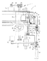
第1図は本発明の液体吸引装置の一例の概略構成を示す。第2図は本発明の液体吸引装置の一例の具体的な構成を示す。この液体吸引装置は本実施例においては血液凝固測定装置に内蔵されている。第2図は血液凝固測定装置の左側面側から見た図であり、図において右側が装置前面で左側が装置内側である。複数のサンプル容器68を一列に並べて保持したサンプルラック66はサンプラによって図において紙面裏から表の方向に1容器分ずつ移送される。
【0017】
第1図に示すように、この液体吸引装置は第1ユニット10と第2ユニット11とから構成されている。第1ユニット10は液体吸引管であるピペット12を保持する第1保持部30及びその第1の保持部30を上下移動させるための駆動源43を備えている。第2ユニット11は第1の保持部30と係合する第2の保持部74及び第2の保持部74を上下移動させるための駆動源86を備えている。第1ユニット10は水平移動可能となっている。二点鎖線は第1ユニット10が最前に位置し、第1保持部30が第2保持部74に近接し両者が係合しうる状態を示す。実線は第1ユニット10が後方に位置し、第1保持部30は第2保持部74から離れ両者は係合し得ない状態を示す。
【0018】
ピペット12は内部通路14(図4参照)を有しており、外径2.0mm、内径1.3mm、全長約130mmのステンレス製の円筒管である。ピペット12の上端部には電線34が接続されている。電線34は液面検知回路35に接続され、ピペット先端が液面に接触する際の容量(キャパシタンス)変化に基づき液面を検知する。ピペット12上端にはチューブ36が接続されそのチューブ36はシリンジポンプなどの液体定量装置37に接続される。本実施例においては第1ユニットは駆動源94、96により水平方向に移動される。
【0019】
第3、4図はピペットの先端部分の部分拡大図、部分拡大断面図である。ピペット12は下端部付近において外径1.2mm、内径0.5mmに細く絞られ管軸に対して図のように斜めに鋭利カットされている。内部通路14は斜めカット面16に開口18する。単に斜めにカットしただけでは斜めカット面16における内壁端21に鋭角のエッジが発生する(上側の半周20には鋭角のエッジ、下側の半周22には鈍角のエッジが発生する)。
【0020】
第5図は従来のピペット13におけるゴムキャップ突き刺し状態を示している。内壁端に鋭角のエッジがあるので、ゴムキャップ突き刺し時に鋭角のエッジ23でゴムキャップ24を切断しその切断されたゴムキャップの一部(ゴムカス)が開口に進入するので、すぐに詰まりが発生する。
【0021】
そこで、上側の半周部分20について鋭角のエッジを除去する面取処理を施した。このことにより内壁端の全周について鋭角のエッジをなくすことができ、少なくとも3万回の連続試験においても詰まりが発生しないことが確認された。ピペット12は下端から約80mmまでの領域の外壁に耐摩耗性を高めるため窒化クロム(CrN)のコーティング処理が施されている。
【0022】
第2図は液体吸引装置の一実施例の一部切り欠き側面図である。44は第1ユニット10の第1シャーシである。40、41はプーリ、42はプーリ40、41に掛け渡されたベルトである。一方のプーリ41は第1の駆動源であるモータ43(本実施例ではステッピングモータ)の軸に直結している。ベルト42の一部に部材を取り付ければ第1のモータ43の回転によりその部材は上下移動することができる。
【0023】
第1ユニット10にはピペット12に上向きの外力が作用したときにこれを検知する外力検知手段54が備えられている。部材48を介してベルト42に取り付けられた部材50は第2シャーシ38に回転可能に支持されている。第2シャーシ38は第1シャーシ44に取り付けられたガイドシャフト46、47により上下移動のみできるようにガイドされている。第2シャーシ38にはピペット12を保持した第1保持部が取り付けられる。第2シャーシ38と部材50の間には圧縮コイルバネなどの付勢手段52が配置されている。
【0024】
ピペット12に外力が作用していない状態では部材50は第2シャーシ38に設けられた部材54を支点として図において時計方向に付勢され第2シャーシに設けられた係止部56に当接されている。よって、第1のモータ43の回転により第1保持部30、第2シャーシ38、部材50は一体化して上下移動する。
【0025】
もし、ピペット下降中にピペット12に物が当接し上向きの外力が作用すると、部材50の部材48側は下方に移動するが第2シャーシ38の支点54側は停止するので、部材50はバネ52の圧縮力に逆らって二点鎖線に示すように部材50は相対的に反時計周りに回転する。この微少な変動をマイクロスイッチなどのセンサ53により検出する。センサ53は電線により外力検知回路55に接続され、外力検知が行われる。
【0026】
58は貫通孔を備え上下移動するピペットのガイド手段として機能するガイド部材である。ガイド部材58は第1シャーシ44に取り付けられている。本実施例ではピペット12は100mm以上の長さを有するので移動時に水平方向のブレを発生させないようにするために設けられている。
【0027】
60は貫通孔63(図1参照)を備えその貫通孔63にポート62から洗浄液を供給しポート64から廃液を排出することによりピペット12壁を洗浄する洗浄部である。洗浄部60は部材70を介してエアーシリンダなどの駆動源72により上下移動される。71は垂直方向に設けられ部材70をガイドするガイドレールである。
【0028】
第2ユニットについて説明する。74は第1保持部30と係合しうる第2保持部である。本実施例では凹部と凸部の嵌まり合いにより両者30、74が連結されるように構成されている。第1保持部30には凸部32が設けられている。第2保持部74にはその凸部32が隙間を有して嵌まる凹部76が設けられている。凸部32の上下方向の幅は約6mm、凹部の上下方向の幅は14mmであり、第1保持部は第2保持部の干渉なしに移動できる余裕、すなわち8mmの不干渉範囲を有している。
【0029】
80は軸受84、85により回転自在に支持され螺旋溝を有するドライブシャフト、82はドライブシャフト80に螺合しドライブシャフト80の回転に伴い上下移動する移動子である。ドライブシャフト80の一端にプーリ89が取り付けられプーリ88、ベルト90を介して第2のモータ(ステッピングモータ)86の回転がドライブシャフト80に伝達される。第2保持部74は部材78を介してこの移動子82に取り付けられガイドレール71にガイドされて上下移動する。
【0030】
第1保持部30と第2保持部74が係合状態にあるときに第1のモータ43への電力供給をなくし第2のモータ86を回転させれば、第2の保持部74が第1の保持部30を押圧し移動させることができる。このとき第1のモータ43は外力により強制的に回転させられることになる。
【0031】
本実施例では第1ユニット10はモータ94により紙面左右方向に水平移動するよう構成されている。さらに、モータ96により紙面表裏方向にも水平移動するよう構成されている。第1ユニット10は装置前側(右側)にあるときに第1の保持部30と第2の保持部74とが係合するようになっている。第1ユニット10が後方(左側)に移動すれば両者の係合は解除され、ピペット12は専ら第1のモータ43の回転により上下移動する。
【0032】
本実施例ではサンプル液である血漿を収容したサンプル容器はサンプラにより例えば10本の容器を装着可能なサンプルラック66に装着されて搬送される。第6図はサンプルラック66を血液凝固測定装置の前面側から見たサンプルラックであり、サンプルラック66は右から左に1サンプル容器ずつ間欠的に移動され、順次ピペット下方に配置される。本実施例において使用されるサンプル容器は3種類に大別される。第1種はサンプルラック66底壁に載置された密閉容器a,b,c,d,e,f(容器底はサンプルラック底壁に当接している)。各容器はキャップが異なっている。第2種はサンプルラック底壁に載置された開放容器g(容器底はサンプルラック底壁に当接している)。第3種はサンプルラック底壁上方に載置した開放容器h,i,j(各容器はフランジを備え、サンプルラック上壁に当接h,jしたりや載置用開放容器上端に当接iしたりしている。いずれの開放容器も底はサンプルラック底壁には当接していない)。
【0033】
本実施例においては、洗浄部60の貫通孔63の下面にはテーパ部61を備えるのでfのような特異な容器(SARSTEDT社のMONOVETTEなる真空採血管)であっても位置ずれすることなく容器を保持することができる。
【0034】
制御部92はプログラムに従い、前記センサからの信号を受信し各モータを駆動させる。液体吸引装置の動作を説明する。
【0035】
<ステップ1:容器キャップの有無検知>
第1ユニット10が最前に位置した状態において、第1のモータ43及び第2のモータ86を回転させて第1保持部30及び第2保持部74を共に下降させることにより前記係合不干渉状態を維持しつつ、ピペット12を初期位置(最上点)から洗浄部60を貫通し所定距離下降させる。その間、制御部92は外力検知回路55からの信号を監視する。ピペット12に外力が作用したと検知されればキャップありの密閉容器であると判断し第1のモータ43を停止させる。ピペット12が所定距離下降しても外力が作用しなければキャップなしの開放容器であると判断する。
【0036】
<ステップ2−1:密閉容器の場合のピペットの下降(突き刺し)>
停止した第1のモータ43をごくわずか逆方向に回転させピペット12先端をキャップから離す。そして、駆動源72を駆動し洗浄部を下降させ洗浄部60下面で容器68のキャップ69を押圧保持する。第1のモータ43への電力供給をストップし、第2のモータ86を回転させる。第2の保持部74は第1の保持部30を押し下げることによりピペット12を容器68のキャップ69に突き刺す(ピペット12は専ら第2のモータ86の力により下降する)。そして、液面検知回路35からの液面検知情報、予め設定された最下点に到達したとの位置情報のいずれかの情報により第2のモータ86は停止させられピペット12も停止する。
【0037】
<ステップ2−2:開放容器の場合のピペットの下降>
継続して第1のモータ43及び第2のモータ86を回転させて、第1の保持部30を第2の保持部74に当接させることなく下降させる(ピペット12は第1のモータ43の力により下降する)。そして、液面検知回路35からの液面検知情報、外力検知回路55からの外力検知情報、予め設定された最下点に到達したとの位置情報のいずれかの情報により第1のモータ43は停止させられピペット12も停止する。
【0038】
<ステップ3:サンプル液吸引>
ピペット12を吸引量に応じて所定距離下降させ、液体定量装置37を動作させピペット12先端の開口18から血漿を所定量吸引する(5μlから500μlまで)。なお、上記ステップ2−1において最下点到達によりピペット12が下降停止した場合、ステップ2−2において外力検知又は最下点到達によりピペット12が下降停止した場合は吸引すべき血漿がないということであるので液の吸引は行わずサンプル液なしとのエラーメッセージを出力する。
【0039】
<ステップ4−1:密閉容器の場合のピペットの上昇(引き抜き)>
第1のモータ43への電力供給をストップしたまま第2のモータ86を逆回転させる。第2の保持部74が第1の保持部30を押し上げることによりピペット12を容器68のキャップ69から引き抜く(ピペット12は専ら第2のモータ86の力により上昇する)。同時に洗浄部60に洗浄液を供給し廃液を排出しピペット12外壁を洗浄する。引き抜きが完了すれば洗浄部60を上昇させ容器68の保持を解除する。ピペット12は初期位置に戻る。
【0040】
<ステップ4−2:開放容器の場合のピペットの上昇>
第1のモータ43、第2のモータ86を逆回転させて、第1の保持部30を第2の保持部74に当接させることなく上昇させる(ピペット12は専ら第1のモータ43の力により上昇する)。同時に洗浄部60に洗浄液を供給し廃液を排出しピペット12外壁を洗浄する。ピペット12は初期位置に戻る。
【0041】
<ステップ5:ピペットの後方移動>
モータ94を回転させ第1ユニット10を後方移動させる。このことにより第1の保持部は第2の保持部からの係合から完全に解除される。また必要に応じてモータ96を回転させ第1ユニットを横方向移動させてもよい。
【0042】
<ステップ6:ピペットの下降>
第1の保持部30は第2の保持部74の係合が解除されているので、第1のモータ43だけを回転させてピペット12を所定量下降させる。
【0043】
<ステップ7:サンプル液吐出>
液体定量装置37を動作させピペット12先端の開口18から反応容器(不図示)内に血漿を所定量吐出する。
【0044】
<ステップ8:ピペットの上昇>
第1のモータ43を逆回転させてピペット12を上昇させる。そしてピペット12の内外壁を洗浄する。例えばモータ94又はモータ96によってピペット12を図示しない洗浄容器へ移動し洗浄する。あるいはピペット12内部通路14に洗浄液を供給し洗浄部60に洗浄液を供給しこれら廃液を洗浄部60から排出しピペット12内外壁を洗浄してもよい。
【0045】
<ステップ9:ピペットの前方移動>
モータ94を逆回転させ第1ユニット10を前方移動させる。ピペット12は初期位置に戻る。第1の保持部は第2の保持部と係合しうる状態になる。
<ステップ10:サンプルラックの移送>
サンプラを駆動させサンプルラック68を1容器分移動させて停止させる。そして、上記工程を順に行う。
【0046】
【発明の効果】
本発明の液体吸引装置は、液体を吸引する液体吸引管を下降させたときに液体吸引管に外力が作用するか否かによって容器識別を行っている。すなわち、栓体の有無を直接的に検知、判定しているので、判定ミスが起こりにくい。また、分析装置等にもともと設けられている液体吸引管や外力検知手段等の構成を利用しているので装置が複雑化、大型化しない。
【0047】
また、判定結果に基いて液体吸引管を各状況に適する仕様で動作させることができる。
【図面の簡単な説明】
【図1】本発明の液体吸引装置の概略構成図である。
【図2】本発明の液体吸引装置の一部切り欠き側面図である。
【図3】液体吸引管の先端部分の側面図である。
【図4】液体吸引管の先端部分の側断面図である。
【図5】従来の液体吸引管におけるゴムキャップ突き刺し時側面図である。
【図6】各種サンプル容器が装着されたサンプルラックの正面図である。
【符号の説明】
10 第1ユニット
11 第2ユニット
12 液体吸引管(ピペット)
16 斜めカット面
20 管内壁端
30 第1の保持部
35 液面検知手段
37 液体定量装置
43 第1の駆動源(モータ)
54 外力検知手段
60 洗浄部
68 サンプル容器
74 第2の保持部
86 第2の駆動源(モータ)
92 制御部[0001]
BACKGROUND OF THE INVENTION
The present invention relates to a liquid suction device capable of identifying a container using a liquid suction tube for sucking a liquid, and can be suitably used in the field of collecting a liquid sample in a sample analyzer or the like.
[0002]
[Prior art]
When a liquid sample is sucked from a sealed container whose container opening is sealed by a stopper such as a rubber cap, a needle-like suction tube whose tip is cut obliquely is used.
[0003]
In order to prevent rubber debris from being clogged in the suction pipe when the cap is pierced, there has been known (a) a suction pipe provided with a suction opening as described in JP-A-9-304400.
[0004]
On the other hand, in order to operate without problems for containers with caps (closed containers) and containers without caps (open containers), (b) as described in Japanese Patent No. 2511549, One having a probe and a needle for an airtight container is known. The open container and the sealed container are identified by reading an identification label or card provided outside the container with a detector.
[0005]
[Problems to be solved by the invention]
In the prior art (b), a label or card and a detector for reading them are required for container identification. For this reason, if the label and the card are not provided correctly, the container cannot be identified correctly. Furthermore, since two types of suction parts are prepared according to the type of container, the configuration is also increased in size and complexity.
[0006]
An object of the present invention is to provide a container identification device that can correctly identify a container with a simple configuration.
[0007]
[Means for Solving the Problems]
In the liquid suction device of the present invention, a container is identified using a liquid suction tube for sucking a liquid. To identify a container is to determine whether or not the target container is a sealed container with a plug, but the presence / absence of a sealed container, the presence / absence of a container plug, the type of container (with a plug) Closed container or open container without stopper).
[0008]
The liquid suction device of the present invention is a liquid suction device that sucks liquid from a container disposed at a predetermined position, and a liquid suction tube that has a sharp tip and can suck the liquid, and the liquid suction tube moves in the vertical direction A drive mechanism for detecting the external force applied to the liquid suction pipe, and a control means for controlling the means. The drive mechanism includes two types of strength sources, When the drive mechanism is driven and the liquid suction tube is moved toward the container, the control means determines that the external force detection means does not detect an external force and that the external force is detected have judged container identification functions as a sealed container, the liquid suction tube is lowered with a small force when not sealed container, so that the control to lower the liquid suction tube with a strong force in the case of the sealed container To do And it features.
[0009]
A container containing a liquid to be collected (for example, a sample liquid to be inspected) is disposed at a predetermined position. The drive mechanism operates and the liquid suction tube moves toward the container. When the container is not a closed container or an open container, the liquid suction tube does not contact the stopper because there is no stopper. The same applies when there is no container itself. Therefore, no external force acts on the liquid suction pipe.
[0010]
When the container is a hermetically sealed container, the liquid suction pipe comes into contact with the stopper because there is a stopper. Therefore, an external force acts on the liquid suction tube. Container distinction can be performed by this difference.
[0011]
As described above, in the present invention, since the presence or absence of the plug is directly detected using the liquid suction tube, a determination error related to container identification is unlikely to occur. In addition, there are few configurations to be newly added, and the entire apparatus is not complicated or enlarged.
[0012]
The obtained determination result is suitably used for operating the liquid suction tube with specifications suitable for each container . Drive kinematic mechanism comprises a strength two driving sources, a liquid suction tube is lowered by a weak force in the case of an open container, controls to lower the liquid suction tube with a strong force in the case of a closed container that Is possible. If there is no container, the liquid suction tube may not be lowered.
[0013]
DETAILED DESCRIPTION OF THE INVENTION
The liquid suction tube used is preferably made of metal in terms of strength and liquid level detection, and the outer wall of the stainless steel pipe is coated with a hard coating such as chromium nitride (CrN) in terms of corrosion resistance and wear resistance. It is preferable that it is made. From the viewpoint of preventing clogging, it is preferable that an acute edge is not generated at the end of the inner wall of the tube at the oblique cut surface at the tip of the tube.
[0014]
Although it does not specifically limit as a liquid attracted | sucked with a liquid suction tube, The blood samples, such as plasma which should be analyzed with an analyzer, are the examples. It is preferable from the viewpoint of automation of analysis processing that the containers containing the liquid to be collected (for example, sample liquid to be inspected) in the liquid suction device are sequentially arranged at predetermined positions by the transfer means. Specifically, a sample rack on which a plurality of containers are mounted or placed can be transferred by a sampler, and the containers can be sequentially arranged below the suction tube.
[0015]
The external force detection means preferably includes a sensor that detects that an object has collided with the tip of the liquid suction tube. This type of sensor is usually referred to as a crash sensor and is provided to detect when a liquid suction pipe collides with an object. As soon as the liquid suction pipe collides with an object, the liquid suction pipe is stopped and retracted, thereby avoiding damage to the liquid suction pipe. In the present invention, container identification can be performed by using this type of crash sensor provided in the liquid suction device.
[0016]
【Example】
FIG. 1 shows a schematic configuration of an example of the liquid suction device of the present invention. FIG. 2 shows a specific configuration of an example of the liquid suction device of the present invention. This liquid suction device is built in the blood coagulation measuring device in this embodiment. FIG. 2 is a view as seen from the left side of the blood coagulation measuring apparatus, in which the right side is the front of the apparatus and the left side is the inside of the apparatus. A
[0017]
As shown in FIG. 1, the liquid suction device includes a
[0018]
The
[0019]
3 and 4 are a partially enlarged view and a partially enlarged sectional view of the tip portion of the pipette. The
[0020]
FIG. 5 shows a state where the
[0021]
Therefore, a chamfering process was performed on the upper half
[0022]
FIG. 2 is a partially cutaway side view of an embodiment of the liquid suction device.
[0023]
The
[0024]
When no external force is applied to the
[0025]
If an object comes into contact with the
[0026]
Reference numeral 58 denotes a guide member that functions as guide means for a pipette that has a through hole and moves up and down. The guide member 58 is attached to the
[0027]
A
[0028]
The second unit will be described.
[0029]
A
[0030]
When the
[0031]
In the present embodiment, the
[0032]
In this embodiment, a sample container containing plasma as a sample solution is mounted on a
[0033]
In this embodiment, since the tapered portion 61 is provided on the lower surface of the through-hole 63 of the
[0034]
The
[0035]
<Step 1: Detection of presence / absence of container cap>
In the state in which the
[0036]
<Step 2-1: Pipette lowering (piercing) in the case of a sealed container>
The stopped
[0037]
<Step 2-2: Lowering of pipette in case of open container>
The
[0038]
<Step 3: Sample suction>
The
[0039]
<Step 4-1: Ascending pipette (withdrawal) in closed container>
The
[0040]
<Step 4-2: Raising the pipette in the case of an open container>
The
[0041]
<Step 5: Backward movement of pipette>
The motor 94 is rotated to move the
[0042]
<Step 6: Lowering the pipette>
Since the
[0043]
<Step 7: Sample liquid discharge>
The
[0044]
<Step 8: Raising the pipette>
The
[0045]
<Step 9: Moving the pipette forward>
The motor 94 is reversely rotated to move the
<Step 10: Transfer of sample rack>
The sampler is driven and the
[0046]
【The invention's effect】
The liquid suction device of the present invention performs container identification based on whether or not an external force acts on the liquid suction pipe when the liquid suction pipe for sucking the liquid is lowered. That is, since the presence or absence of the plug is directly detected and determined, a determination error is unlikely to occur. In addition, since the configuration of the liquid suction tube, the external force detection means, and the like provided in the analyzer is used, the apparatus does not become complicated and large.
[0047]
Further, the liquid suction tube can be operated with specifications suitable for each situation based on the determination result.
[Brief description of the drawings]
FIG. 1 is a schematic configuration diagram of a liquid suction device of the present invention.
FIG. 2 is a partially cutaway side view of the liquid suction device of the present invention.
FIG. 3 is a side view of a tip portion of a liquid suction tube.
FIG. 4 is a side sectional view of a tip portion of a liquid suction tube.
FIG. 5 is a side view of a conventional liquid suction tube when a rubber cap is pierced.
FIG. 6 is a front view of a sample rack on which various sample containers are mounted.
[Explanation of symbols]
10 First unit 11
16
54 External force detection means 60
92 Control unit
Claims (1)
先端が鋭利形成され液体を吸引することができる液体吸引管と、
液体吸引管を上下方向に移動させる駆動機構と、
液体吸引管に上向きの外力が作用したことを検知する外力検知手段と、
上記これら手段を制御する制御手段と、を備え、
駆動機構は、強弱2種類の駆動源を備え、
制御手段は、駆動機構を駆動させて液体吸引管を容器に向けて移動させたときに、外力検知手段により外力が検知されなかった場合は密閉容器ではないと判定し、外力が検知された場合は密閉容器であると判定する機能を有し、密閉容器ではない場合には弱い力で液体吸引管を下降させ、密閉容器の場合には強い力で液体吸引管を下降させるよう制御することを特徴とする液体吸引装置。 In a liquid suction device that sucks liquid from a container disposed at a predetermined position,
A liquid suction tube whose tip is sharply formed and capable of sucking liquid;
A drive mechanism for moving the liquid suction pipe in the vertical direction;
An external force detection means for detecting that an upward external force is applied to the liquid suction pipe;
Control means for controlling these means, and
The drive mechanism has two types of driving sources, strong and weak.
When the drive mechanism is driven and the liquid suction tube is moved toward the container, the control means determines that the external force detection means does not detect an external force and that the external force is detected it has a function of determining that the closed container, the liquid suction tube is lowered with a small force when not sealed container, to so that the control to lower the liquid suction tube with a strong force in the case of the sealed container A liquid suction device characterized by the above .
Priority Applications (4)
| Application Number | Priority Date | Filing Date | Title |
|---|---|---|---|
| JP25964798A JP3836609B2 (en) | 1998-09-14 | 1998-09-14 | Liquid suction device |
| EP99306856A EP0984285B1 (en) | 1998-08-31 | 1999-08-27 | Sample aspirator having dual inter-operating manipulation units |
| DE1999614029 DE69914029T2 (en) | 1998-08-31 | 1999-08-27 | Sample aspirator with two cooperating handling units |
| US09/385,853 US6171280B1 (en) | 1998-08-31 | 1999-08-30 | Aspirator having dual inter-operating manipulation units |
Applications Claiming Priority (1)
| Application Number | Priority Date | Filing Date | Title |
|---|---|---|---|
| JP25964798A JP3836609B2 (en) | 1998-09-14 | 1998-09-14 | Liquid suction device |
Publications (3)
| Publication Number | Publication Date |
|---|---|
| JP2000088862A JP2000088862A (en) | 2000-03-31 |
| JP2000088862A5 JP2000088862A5 (en) | 2005-11-04 |
| JP3836609B2 true JP3836609B2 (en) | 2006-10-25 |
Family
ID=17336964
Family Applications (1)
| Application Number | Title | Priority Date | Filing Date |
|---|---|---|---|
| JP25964798A Expired - Fee Related JP3836609B2 (en) | 1998-08-31 | 1998-09-14 | Liquid suction device |
Country Status (1)
| Country | Link |
|---|---|
| JP (1) | JP3836609B2 (en) |
Families Citing this family (7)
| Publication number | Priority date | Publication date | Assignee | Title |
|---|---|---|---|---|
| JP4351875B2 (en) | 2003-07-15 | 2009-10-28 | シスメックス株式会社 | Liquid suction device and analyzer equipped with the same |
| JP2005069830A (en) * | 2003-08-22 | 2005-03-17 | Sysmex Corp | Dispensation chip and analyzer using it |
| US7481978B2 (en) * | 2005-03-23 | 2009-01-27 | Beckman Coulter, Inc. | Apparatus for aspirating liquids from sealed containers |
| JP4980671B2 (en) | 2006-08-18 | 2012-07-18 | シスメックス株式会社 | Blood sample analyzer |
| JP5426498B2 (en) * | 2010-08-18 | 2014-02-26 | シスメックス株式会社 | Sample suction device |
| JP5336555B2 (en) * | 2011-07-21 | 2013-11-06 | シスメックス株式会社 | Sample analyzer |
| CN105829896B (en) * | 2014-01-07 | 2019-01-22 | 株式会社日立高新技术 | Automatic analysing apparatus |
-
1998
- 1998-09-14 JP JP25964798A patent/JP3836609B2/en not_active Expired - Fee Related
Also Published As
| Publication number | Publication date |
|---|---|
| JP2000088862A (en) | 2000-03-31 |
Similar Documents
| Publication | Publication Date | Title |
|---|---|---|
| US6171280B1 (en) | Aspirator having dual inter-operating manipulation units | |
| JP4938082B2 (en) | Cleaning device, suction nozzle clogging detection method, and automatic analyzer | |
| US5380486A (en) | Apparatus for taking liquid content for use in analysis out of container | |
| EP1557674B1 (en) | Analyzer and analyzing method using disposable tips | |
| JP5686744B2 (en) | Automatic analyzer | |
| WO2006123771A1 (en) | Method of detecting dispensed quantity, and liquid suction monitoring dispensing apparatus | |
| JP4938083B2 (en) | Cleaning device, cleaning nozzle clogging detection method, and automatic analyzer | |
| US6358471B1 (en) | Automatic measuring apparatus | |
| JP2008076256A (en) | Specimen sampler and autoanalyzer using it | |
| JP6567890B2 (en) | Automatic analyzer | |
| JP3771380B2 (en) | Liquid suction device | |
| JP3836609B2 (en) | Liquid suction device | |
| JP3907819B2 (en) | Liquid level detector | |
| JPH0121467B2 (en) | ||
| JP2006098226A (en) | Anomaly detection method for syringe pump, liquid suction/discharge apparatus, and biochemical analyzer | |
| JP4045211B2 (en) | Automatic analyzer | |
| JP2010096640A (en) | Dispenser | |
| JP3694755B2 (en) | Pipetting method, pipetting device, and storage medium | |
| JP3120180U (en) | Automatic analyzer | |
| JP6121743B2 (en) | Automatic analyzer | |
| JP2000074928A (en) | Liquid suction pipe | |
| JP3860313B2 (en) | Ultrasonic liquid level detection device and liquid level detection method using this device | |
| JP2002022756A (en) | Liquid suction pipe and its manufacturing method | |
| JP3926546B2 (en) | Spotting detection method and spotting detection device | |
| JPH049734A (en) | Apparatus for dispensing liquid sample |
Legal Events
| Date | Code | Title | Description |
|---|---|---|---|
| A521 | Written amendment |
Free format text: JAPANESE INTERMEDIATE CODE: A523 Effective date: 20050913 |
|
| A621 | Written request for application examination |
Free format text: JAPANESE INTERMEDIATE CODE: A621 Effective date: 20050913 |
|
| A977 | Report on retrieval |
Free format text: JAPANESE INTERMEDIATE CODE: A971007 Effective date: 20051220 |
|
| A131 | Notification of reasons for refusal |
Free format text: JAPANESE INTERMEDIATE CODE: A131 Effective date: 20060110 |
|
| A521 | Written amendment |
Free format text: JAPANESE INTERMEDIATE CODE: A523 Effective date: 20060309 |
|
| A131 | Notification of reasons for refusal |
Free format text: JAPANESE INTERMEDIATE CODE: A131 Effective date: 20060411 |
|
| A521 | Written amendment |
Free format text: JAPANESE INTERMEDIATE CODE: A523 Effective date: 20060612 |
|
| TRDD | Decision of grant or rejection written | ||
| A01 | Written decision to grant a patent or to grant a registration (utility model) |
Free format text: JAPANESE INTERMEDIATE CODE: A01 Effective date: 20060711 |
|
| A61 | First payment of annual fees (during grant procedure) |
Free format text: JAPANESE INTERMEDIATE CODE: A61 Effective date: 20060727 |
|
| R150 | Certificate of patent (=grant) or registration of utility model |
Free format text: JAPANESE INTERMEDIATE CODE: R150 |
|
| FPAY | Renewal fee payment (prs date is renewal date of database) |
Free format text: PAYMENT UNTIL: 20090804 Year of fee payment: 3 |
|
| FPAY | Renewal fee payment (prs date is renewal date of database) |
Free format text: PAYMENT UNTIL: 20120804 Year of fee payment: 6 |
|
| FPAY | Renewal fee payment (prs date is renewal date of database) |
Free format text: PAYMENT UNTIL: 20120804 Year of fee payment: 6 |
|
| FPAY | Renewal fee payment (prs date is renewal date of database) |
Free format text: PAYMENT UNTIL: 20150804 Year of fee payment: 9 |
|
| LAPS | Cancellation because of no payment of annual fees |