JP3771006B2 - D / A converter - Google Patents
D / A converter Download PDFInfo
- Publication number
- JP3771006B2 JP3771006B2 JP18377397A JP18377397A JP3771006B2 JP 3771006 B2 JP3771006 B2 JP 3771006B2 JP 18377397 A JP18377397 A JP 18377397A JP 18377397 A JP18377397 A JP 18377397A JP 3771006 B2 JP3771006 B2 JP 3771006B2
- Authority
- JP
- Japan
- Prior art keywords
- start position
- digital signal
- converter
- unit
- output
- Prior art date
- Legal status (The legal status is an assumption and is not a legal conclusion. Google has not performed a legal analysis and makes no representation as to the accuracy of the status listed.)
- Expired - Fee Related
Links
Images


Classifications
-
- H—ELECTRICITY
- H03—ELECTRONIC CIRCUITRY
- H03M—CODING; DECODING; CODE CONVERSION IN GENERAL
- H03M1/00—Analogue/digital conversion; Digital/analogue conversion
- H03M1/06—Continuously compensating for, or preventing, undesired influence of physical parameters
- H03M1/0617—Continuously compensating for, or preventing, undesired influence of physical parameters characterised by the use of methods or means not specific to a particular type of detrimental influence
- H03M1/0634—Continuously compensating for, or preventing, undesired influence of physical parameters characterised by the use of methods or means not specific to a particular type of detrimental influence by averaging out the errors, e.g. using sliding scale
- H03M1/0656—Continuously compensating for, or preventing, undesired influence of physical parameters characterised by the use of methods or means not specific to a particular type of detrimental influence by averaging out the errors, e.g. using sliding scale in the time domain, e.g. using intended jitter as a dither signal
- H03M1/066—Continuously compensating for, or preventing, undesired influence of physical parameters characterised by the use of methods or means not specific to a particular type of detrimental influence by averaging out the errors, e.g. using sliding scale in the time domain, e.g. using intended jitter as a dither signal by continuously permuting the elements used, i.e. dynamic element matching
- H03M1/0663—Continuously compensating for, or preventing, undesired influence of physical parameters characterised by the use of methods or means not specific to a particular type of detrimental influence by averaging out the errors, e.g. using sliding scale in the time domain, e.g. using intended jitter as a dither signal by continuously permuting the elements used, i.e. dynamic element matching using clocked averaging
-
- H—ELECTRICITY
- H03—ELECTRONIC CIRCUITRY
- H03M—CODING; DECODING; CODE CONVERSION IN GENERAL
- H03M1/00—Analogue/digital conversion; Digital/analogue conversion
- H03M1/66—Digital/analogue converters
- H03M1/74—Simultaneous conversion
- H03M1/742—Simultaneous conversion using current sources as quantisation value generators
- H03M1/747—Simultaneous conversion using current sources as quantisation value generators with equal currents which are switched by unary decoded digital signals
-
- H—ELECTRICITY
- H03—ELECTRONIC CIRCUITRY
- H03M—CODING; DECODING; CODE CONVERSION IN GENERAL
- H03M3/00—Conversion of analogue values to or from differential modulation
- H03M3/30—Delta-sigma modulation
- H03M3/458—Analogue/digital converters using delta-sigma modulation as an intermediate step
- H03M3/464—Details of the digital/analogue conversion in the feedback path
-
- H—ELECTRICITY
- H03—ELECTRONIC CIRCUITRY
- H03M—CODING; DECODING; CODE CONVERSION IN GENERAL
- H03M3/00—Conversion of analogue values to or from differential modulation
- H03M3/30—Delta-sigma modulation
- H03M3/50—Digital/analogue converters using delta-sigma modulation as an intermediate step
- H03M3/502—Details of the final digital/analogue conversion following the digital delta-sigma modulation
Abstract
Description
【0001】
【発明の属する技術分野】
この発明は、ディジタル信号に基づく複数の電流源のオン・オフの切り替えにより、ディジタル信号をアナログ信号に変換するD/Aコンバータ(DAC)に関する。
【0002】
【従来の技術】
現在、音声帯域のデータ変換方式として、オーバーサンプリング△Σ変換方式が広く用いられている。図30はオーバーサンプリング△Σ変換方式を用いたA/Dコンバータの構成を示すブロック図である。同図に示すように、アナログ入力信号AIをアンチエリアシングフィルタ11に与える。アンチエリアシングフィルタ11はアナログ入力信号AIの高周波成分を除去してΔΣモジュレータ12に与える。
【0003】
ΔΣモジュレータ12はアナログ入力信号AIを標本化周波数fSより大きな周波数(n(≧2)・fS)でオーバーサンプリングしながらノイズシェーピングして得られるΔΣ変調済みディジタル信号をデシメーションフィルタ13に与える。デシメーションフィルタ13はΔΣモジュレータ12より得たディジタル信号のうちn個に1個の割合で抜き取って得られる信号をディジタル出力信号DOとして出力する。
【0004】
ΔΣモジュレータ12は減算器14、積分器15、量子化器16及び内部DAC17から構成され、積分器15は減算器14の出力である差分アナログ信号を積分し、量子化器16は積分器15の出力を量子化してディジタル信号(ノイズ成分を含む)としてデシメーションフィルタ13に出力するとともに、内部DAC17に出力する。内部DAC17はディジタル信号をD/A変換して、減算器14に減算用のアナログ信号としてフィードバックする。なお、積分器15は1/(n・fS)期間の積分処理を行い、1オーバーサンプリング時間の遅延処理を機能を備える。
【0005】
そして、減算器14はアンチエリアシングフィルタ11から得たアナログ入力信号AIから内部DAC17より得た減算用のアナログ信号(アナログAIの1オーバーサンプリング遅延信号に相当)を差し引いて差分アナログ信号を積分器15に出力する。その結果、減算器14、積分器15、量子化器16及び内部DAC17によって形成されるノイズシェーピングループによってアナログ入力信号AIに生じるノイズ成分が除去されて精度の高いディジタル信号をデシメーションフィルタ13に与えることができる。
【0006】
図31はオーバーサンプリング△Σ変換方式のD/Aコンバータの構成を示すブロック図である。同図に示すように、補間フィルタ21はディジタル入力信号DIより得られる原データに基づき演算によって補間データを求め、原データに補間データを挿入することにより、周波数n・fSでオーバーサンプリングしたディジタル信号をΔΣモジュレータ22に出力する。
【0007】
ΔΣモジュレータ22はオーバーサンプリングしたディジタル信号をノイズシェーピングして内部DAC23に与える。内部DAC23はΔΣモジュレータ22より得たΔΣ変調済みディジタル信号をD/A変換してアナログ信号をローパスフィルタ24に出力する。ローパスフィルタ24は内部DAC23より得たアナログ信号の高周波成分を除去してアナログ出力信号AOを出力する。
【0008】
ΔΣモジュレータ22は減算器25、積分器26及び量子化器27から構成され、積分器26は減算器25の出力である差分ディジタル信号を積分し、量子化器27は積分器26の出力を量子化してΔΣ変調済みディジタル信号(ノイズ成分を含む)として内部DAC23に出力するとともに、減算器24に減算用ディジタル信号としてフィードバックする。なお、積分器26は1/(n・fS)期間の積分処理を行い、1オーバーサンプリング時間の遅延処理を機能を備える。
【0009】
そして、減算器25は、補間フィルタ21から得たディジタル信号から量子化器27より得た減算用のディジタル信号(補間フィルタ21から得たディジタル信号の1オーバーサンプリング遅延信号に相当)を差し引いて得られる差分ディジタル信号を積分器26に出力することになる。その結果、減算器25、積分器26及び量子化器27によって形成されるノイズシェーピングループによって、ディジタル信号に生じるノイズ成分が除去されて精度の高いディジタル信号を内部DAC23に出力することができる。
【0010】
上述したように、オーバーサンプリング△Σ変換方式ではA/Dコンバータ及びD/Aコンバータ共に内部DACを必要とする。この内部DACは、A/Dコンバータ内ではノイズシェーピングループのフィードバック信号処理回路として、またD/Aコンバータ内ではノイズシェーピングされたディジタル信号をアナログ信号に変換する回路として用いられている。この内部DACには、従来1ビットのDACが用いられてきた。1ビットDACを用いると、構成が簡単である上に、DACのディジタル入力に対するアナログ出力の直線性が保証されるためである。しかしその反面、量子化ノイズが大きく、系の安定性に問題があった。そこで近年、内部DACに多ビットDACが導入されてきている。しかし、多ビットDACでは、各構成要素のマッチングを取ることが困難であり、1ビットDACでは保証されていた上記直線性が得られなくなる。
【0011】
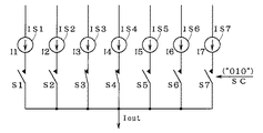
図32は従来の3ビットD/Aコンバータの内部構成を示す説明図である。同図に示すように、一端が電源Vccに接続された単位電流源IS1〜IS7のそれぞれの他端がスイッチS1〜S7の一端に接続される。そして、スイッチS1〜S7の他端が共通に出力部であるノードN1に接続される。図32に示すように、3ビットD/Aコンバータには、(23−1)の電流源が必要となる。なお、各電流源IS1〜IS7が供給する電流I1〜I7の電流量は同一のIEになるように設定される。
【0012】
スイッチ制御回路10は、ディジタル信号DIGに基づき制御信号SCをスイッチS1〜S7に出力し、スイッチS1〜S7のうちディジタル信号DIGに応じた個数のスイッチをスイッチS1から昇順にオン状態にし、他のスイッチをオフ状態とする。
【0013】
例えば、ディジタル信号DIGが“011”(3)の場合、図33に示すように、スイッチ制御回路10はスイッチS1〜S3をオン状態、スイッチS4〜S7をオフ状態とする制御信号SCを出力する。例えば、ディジタル信号DIGが“010”(2)の場合、図34に示すように、スイッチ制御回路10はスイッチS1,S2をオン状態、スイッチS3〜S7をオフ状態とする制御信号SCを出力する。
【0014】
そして、ノードN1より得られる電流が出力電流IoutとしてI−V変換器2に与えられ、I−V変換器2が出力電流Ioutを電流/電圧変換してアナログ信号である出力電圧Voutを出力する。したがって、図33の例では出力電流Iout=3・IEとなり、図34の例では出力電流Iout=2・IEとなる。
【0015】
このように、電流源を用いた多ビットD/Aコンバータは、入力ディジタルデータ(DIG)に応じて所定数の電流源を有効にすることにより、ディジタルデータDIGをアナログ信号(出力電圧Vout)に変換することができる。
【0016】
また、特開平4−152715号公報に入力コードに応じた個数の容量をランダムに選択してD/A変換を行うD/Aコンバータが開示されている。
【0017】
【発明が解決しようとする課題】
しかしながら、各単位電流源IS1〜IS7の特性(電流I1〜I7それぞれの電流量)を完全に一致させることは、プロセスのばらつきやレイアウト時の周辺の回路素子等の影響により困難である。
【0018】
従来の3ビットD/Aコンバータでは、ディジタル入力信号(DIG)に対して、常に同じ電流源から有効にしている(例えば、ディジタル信号DIGが“000”以外の場合は常にスイッチS1をオンして電流源IS1を有効にしている)。
【0019】
このため、特定の電流源(図32の例では電流源IS1)が有効とされる回数が多く、D/Aコンバータの出力に個々の電流源の特性差が顕著にあらわれ、直線性の劣化の原因となっていた。
【0020】
従来の多ビットD/Aコンバータは以上のように構成されており、ディジタル入力に対するアナログ出力の直線性が悪いという問題点があった。
【0021】
この発明は上記問題点を解決するためになされたもので、ディジタル入力に対するアナログ出力の直線性の改善を図った多ビットD/Aコンバータを得ることを目的とする。
【0022】
【課題を解決するための手段】
この発明に係る請求項1記載のD/Aコンバータは、クロック信号に同期して複数ビットのディジタル信号をアナログ信号に変換し、出力部に対して所定の順序に並列に接続された複数の単位電気量生成部を備え、前記複数の単位電気量生成部のうち選択された数の単位電気量生成部に関連した電気量が前記出力部に現れ、前記クロック信号に同期して前記複数の単位電気量生成部の選択スタート位置を順次変更して決定するスタート位置決定部と、前記クロック信号に同期して前記ディジタル信号を受け、前記複数の単位電気量生成部のうち前記ディジタル信号で決定される個数の単位電気量生成部を、前記選択スタート位置から前記所定の順序にそって選択する選択部と、前記出力部より得られる電気量に基づき前記アナログ信号を出力するアナログ信号出力部とをさらに備えて構成される。
【0023】
加えて、請求項1記載のD/Aコンバータにおいて、前記ディジタル信号はN(≧2)ビットのディジタル信号を含み、前記複数の単位電気量生成部はL(≧3)個の単位電気量生成部を含み、前記スタート位置決定部は、前記クロック信号に同期して前記所定の順序にそって変位個数A(<L)個ずつずらせながら前記選択スタート位置を決定する。
【0026】
また、請求項2記載のD/Aコンバータにおいて、前記ディジタル信号のビット数Nと前記単位電気量生成部の個数Lとは{L>2N−1}の関係にある。
【0027】
また、請求項3記載のD/Aコンバータにおいて、前記単位電気量生成部の個数Lと前記変位個数Aとは互いに素の関係にある。
【0028】
また、請求項4記載のD/Aコンバータにおいて、前記ディジタル信号のビット数Nと前記単位電気量生成部の個数Lとは{L=2N}の関係にある。
【0033】
【発明の実施の形態】
<実施の形態1>
図1はこの発明の実施の形態1であるN(N≧2)ビットD/Aコンバータの構成を示す説明図である。同図に示すように、一端が電源Vccに接続された単位電流源IS1〜ISMのそれぞれの他端がスイッチS1〜SMの一端に接続される。なお、Mは必要電流源数であり、M=2N−1となる。
【0034】
そして、スイッチS1〜SMの他端が共通にノードN1に接続される。なお、NビットD/Aコンバータには、また、各電流源IS1〜ISMが供給する電流I1〜IMの電流量はほぼ同一のIEになるように設定される。
【0035】
スイッチ制御回路1は、ディジタル信号DIGに基づき制御信号SCをスイッチS1〜SMに出力し、スイッチS1〜SMのうちディジタル信号DIGに応じた個数のスイッチをスタート位置決定回路3で決定されるスイッチから昇順(“1”からMにかけて,Mの次は“1”)にオン状態にし、他のスイッチをオフ状態とする。
【0036】
スタート位置決定回路3は、ディジタル信号DIGの入力タイミングを指示するクロック信号CLKに基づき、クロック信号CLKの1サイクル中に取り込まれるディジタル信号DIGの入力毎に選択スタート位置となるスイッチをS1,S3,S5…という具合に順次変更して選択スタート位置を決定する。
【0037】
例えば、N=3(M=7)でディジタル信号DIGを“011”(3)、“010”(2)の順で与え、スタート位置決定回路3がS1,S3の順にスタート位置を決定した場合、まず、図4に示すように、スイッチ制御回路1はスイッチS1〜S3をオン状態、スイッチS4〜S7をオフ状態とする制御信号SCを出力し、次に、図5に示すように、スイッチS3,S4をオン状態、スイッチS1,S2,S5〜S7をオフ状態とする制御信号SCを出力する。
【0038】
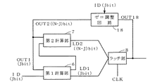
図2はスタート位置決定回路3の内部構成を示すブロック図である。同図に示すように、スタート位置決定回路3は第1加算部6、第2加算部7及びラッチ部8から構成される。
【0039】
第1加算部6は変位データID(J(≦N)ビット)とラッチ部8でラッチされた前回のスタート位置を示すNビットのラッチデータLDのうち下位Jビットからなる部分ラッチデータLD1との加算処理を行い、そのJビット加算結果OUT1とキャリー出力COUTを出力する。
【0040】
第2加算部7は第1加算部6からのキャリー出力COUTとラッチデータLDのうち上位(N−J)ビットの部分ラッチデータとの加算処理を行い、(N−J)ビットの加算結果OUT2を出力する。
【0041】
ゼロ調整回路18は加算結果OUT2を上位、加算結果OUT1を下位として加算結果{OUT1+OUT2}がオールゼロ以外のときは、そのまま加算出力OUT18として出力し、オールゼロのときは下位Jビットを変位データID、上位ビットを“0”とした値を加算出力OUT18して出力する。
【0042】
ラッチ部8は、フリップフロップ等から構成され、クロック信号CLKによるタイミング制御で、ゼロ調整回路18の加算結果OUT18を新たなNビットのラッチデータLDとして格納する。また、ラッチ部8はリセット時に初期値として“1”が設定される。したがって、ラッチデータLDはオールゼロを除くM種類存在することになり、M種類のラッチデータLDとM個の電流源ISとを1対1に対応させることにより、電流源ISの選択スタート位置をラッチデータLDによって規定することができる。
【0043】
図3は、N=3、J=2である場合の図2における第1加算部6及び第2加算部7の具体的構成を示す回路図である。同図に示すように、第1加算部6は半加算器31と全加算器32とから構成され、半加算器31はA入力に最下位ビットの変位データID(B0)を受け、B入力に最下位ビットの部分ラッチデータLD1(B0)を受け、加算出力Sより最下位ビットの加算結果OUT1(B0)を出力し、キャリー出力を全加算器32のキャリー入力CIに与える。
【0044】
全加算器32はA入力に第1ビットの変位データID(B1)を受け、B入力に第1ビットの部分ラッチデータLD1(B1)を受け、加算出力Sより第1ビットの加算結果OUT1(B1)を出力し、キャリー出力COUTを第2加算部7に出力する。
【0045】
第2加算部7は半加算器33によって構成され、半加算器33はA入力に全加算器32のキャリー出力COUTを受け、B入力に最上位ビットの部分ラッチデータLD2(B2)を受け、加算出力Sより最上位ビットの加算結果OUT2(B2)を出力する。
【0046】
上記した構成の図2及び図3で示す構成のスタート位置決定回路3において、3ビットのラッチデータLDの“001”〜“111”それぞれに電流源IS1〜IS7を対応させることにより、1回目の選択スタート位置は電流源IS1(スイッチS1をオンさせる)で、2回目のスタート位置が電流源IS4となり、以降、IS7,IS2,IS5,IS3,IS6,IS1…の順に電流源ISの選択スタート位置を決定することができる。
【0047】
なお、第1加算部6は初段を除き全加算器で構成する必要があるが、第2加算部7は変位データIDを入力することなく前段のキャリー出力を次段の加算入力に接続することにより半加算器のみで構成することができ、第1加算部6に比べて簡単な回路構成で実現できる。
【0048】
このように、スタート位置決定回路3は、基本的に変位データIDを加算しながらM通りの出力値を採るように構成するように、Nビット用の加算器とラッチ部と簡単な論理回路(ゼロ調整回路18)とからなる比較的簡単な回路構成で実現することができる。
【0049】
図1に戻って、ノードN1より得られる電流が出力電流IoutとしてI−V変換器2に与えられる。このとき、図4の例では出力電流Iout=3・IEとなり、図5の例では出力電流Iout=2・IEとなる。そして、I−V変換器2は出力電流Ioutを電流/電圧変換してアナログ信号である出力電圧Voutを出力する。
【0050】
このように、実施の形態1のNビットD/Aコンバータは、入力ディジタルデータ(DIG)に応じて、ディジタル信号DIGのサンプリング毎にスタート位置決定回路3で決定される選択スタート位置の電流源からディジタル信号DIGによって決定される個数数の電流源を選択することにより、ディジタルデータDIGをアナログ信号(出力電圧Vout)に変換している。
【0051】
したがって、ディジタル信号DIGの値が同一の場合でも選択される電流源の組合せが増え、ディジタル信号DIGの値に関係なく電流源IS1〜ISMを片寄りなく選択することができ、D/Aコンバータのアナログ出力に電流源個々の特性差があらわれにくくなり、ディジタル入力に対するアナログ出力の直線性の劣化を有効に抑えることができる。
【0052】
<実施の形態2>
実施の形態1ではスタート位置決定回路3により決定される選択スタート位置はサンプリング毎に変更されることのみ示したが、電流源IS1〜IS7をできるだけ片寄りなく選択するようにスタート位置を変更するようにしたのが実施の形態2である。したがって、実施の形態2のD/Aコンバータは、スタート位置決定回路3による選択スタート位置の決定方法を下記のように行う以外は図1で示した実施の形態1と同様の全体構成を採る。
【0053】
スタート位置決定回路3は、NビットのD/Aコンバータにおいて電流源の個数M(=2N−1)とAとが互いに素で、かつM>Aなる正数Aを見いだし、変位個数Aずつ選択スタート位置をずらせて決定する。
【0054】
例えば、N=3、すなわちM=7のとき、A=5(7と5とは互いに素)を選択すると、1回目のスタート位置は電流源IS1(スイッチS1をオンにする)で、2回目のスタート位置が電流源IS6となり、以降、IS4,IS2,IS7,IS5,IS3,IS1,IS6,…と比較的大きくずらせながら片寄りが全くないように全ての電流源ISを選択スタート位置として選択することができる。
【0055】
このとき、1回目のサンプリングでディジタル信号DIG“011”(3)を取り込むと、図6に示すように、電流源IS1〜IS3が選択され、2回目のサンプリングでディジタル信号DIG“010”(2)を取り込むと、図7に示すように、電流源IS6,IS7が選択される。
【0056】
このように、実施の形態2のD/Aコンバータにおけるスタート位置決定回路3は、電流源の個数と素の関係にある変位個数ずつずらして選択スタート位置を決定することにより、M個のスタート位置の自由度ができ、ディジタル信号DIGの値に対応して選択される電流源の組合せを最大限に増加させることができ、その結果、D/Aコンバータのアナログ出力に個々の電流源の特性差がより一層あらわれにくくなり、ディジタル入力に対するアナログ出力の直線性を向上させることができる。
【0057】
<実施の形態3>
図8はこの発明の実施の形態3であるN(N≧2)ビットD/Aコンバータの構成を示す説明図である。同図に示すように、一端が電源Vccに接続された単位電流源IS1〜IS(M+K)のそれぞれの他端がスイッチS1〜S(M+K)の一端に接続される。なお、Mは必要電流源数であり、M=2N−1となり、Kは余剰電流源数である。
【0058】
そして、スイッチS1〜S(M+K)の他端が共通にノードN1に接続される。なお、NビットD/Aコンバータには、また、各電流源IS1〜IS(M+K)が供給する電流I1〜I(M+K)の電流量はほぼ同一のIEになるように設定される。
【0059】
スイッチ制御回路1Aは、ディジタル信号DIGに基づき制御信号SCをスイッチS1〜S(M+K)に出力し、スイッチS1〜S(M+K)のうちディジタル信号DIGに応じた個数のスイッチをスタート位置決定回路3Aで決定されるスイッチから昇順にオン状態にし、他のスイッチをオフ状態とする。
【0060】
スタート位置決定回路3Aは、ディジタル信号DIGの入力タイミングを指示するクロック信号CLKに基づき、ディジタル信号DIGの入力毎にスタートスイッチをS1,S3,S5…という具合に順次変更して選択スタート位置を決定する。
【0061】
例えば、ディジタル信号DIGを“011”(3)、“010”(2)の順で与え、スタート位置決定回路3AがS1,S(M+1)の順に選択スタート位置を決定した場合、まず、図9に示すように、スイッチ制御回路1AはスイッチS1〜S3をオン状態、スイッチS4〜S(M+K)をオフ状態とする制御信号SCを出力し、次に、図10に示すように、スイッチS(M+1),S(M+2)をオン状態、スイッチS1〜SM,S(M+3)〜S(M+K)をオフ状態とする制御信号SCを出力する。
【0062】
ノードN1より得られる電流が出力電流IoutとしてI−V変換器2に与えられる。このとき、図9の例では出力電流Iout=3・IEとなり、図10の例では出力電流Iout=2・IEとなる。そして、I−V変換器2が出力電流Ioutを電流/電圧変換してアナログ信号である出力電圧Voutを出力する。
【0063】
このように、実施の形態3のNビットD/Aコンバータは、入力ディジタルデータ(DIG)に応じて、ディジタル信号DIGのサンプリング毎にスタート位置決定回路3Aで決定される選択スタート位置の電流源から、ディジタル信号DIGで決定される個数の電流源を有効にすることにより、ディジタルデータDIGをアナログ信号(出力電圧Vout)に変換している。
【0064】
したがって、ディジタル信号DIGの値が同一の場合でも選択される電流源の組合せがより一層増え、ディジタル信号DIGの値に関係なく電流源IS1〜IS(M+K)を片寄りなく選択することができ、D/Aコンバータのアナログ出力に電流源個々の特性差があらわれにくくなり、ディジタル入力に対するアナログ出力の直線性の劣化を有効に抑えることができる。
【0065】
さらに、実施の形態3のD/Aコンバータは、K個の余剰電流源を用意し、実施の形態1に比べ選択スタート位置の自由度を増やすことにより、D/Aコンバータのアナログ出力に電流源個々の特性差がより一層あらわれにくくなり、実施の形態1以上に直線性の劣化を効果的に改善することができる。
【0066】
<実施の形態4>
実施の形態3ではスタート位置決定回路3Aにより決定される選択スタート位置はサンプリング毎に変更されることのみ示したが、電流源IS1〜IS(M+K)をできるだけ片寄りなく選択するように選択スタート位置を変更するようにしたのが実施の形態4である。したがって、実施の形態4のD/Aコンバータは、スタート位置決定回路3Aによるスタート位置の決定方法を下記のように行う以外は図8で示した実施の形態3と同様の全体構成を採る。
【0067】
スタート位置決定回路3Aは、NビットのD/Aコンバータにおいて電流源の個数(M+K)とAとが互いに素で、かつM>Aなる正数Aを見いだし、変位個数Aずつずらせて選択スタート位置を決定する。
【0068】
例えば、N=3(すなわちM=7)でK=6のとき、A=8(13(M+K))と8とは互いに素)を選択すると、1回目のスタート位置は電流源IS1(スイッチS1をオン)で、2回目のスタート位置が電流源IS9となり、以降、IS4,IS12,IS7,IS2,IS10,IS5,IS13,IS8,IS3,IS11,IS5…と比較的大きくずらせながら片寄りが全くないように全ての電流源ISを選択することができる。
【0069】
このとき、1回目のサンプリングでディジタル信号DIG“011”(3)を取り込むと、図11に示すように、電流源IS1〜IS3が選択され、2回目のサンプリングでディジタル信号DIG“010”(2)を取り込むと、図12に示すように、電流源IS9,IS10が選択される。
【0070】
このように、実施の形態4のD/Aコンバータにおけるスタート位置決定回路3Aは、電流源の個数(M+K)と素の関係にある変位個数ずつずらして選択スタート位置を決定することにより、余剰電流源の個数を加味した(M+K)個のスタート位置の自由度ができ、ディジタル信号DIGの値に対応して選択される電流源の組合せを最大限に増加させることができ、その結果、D/Aコンバータの出力に個々の電流源の特性差がより一層あらわれにくくなり、ディジタル入力に対するアナログ出力の直線性を向上させることができる。
【0071】
<実施の形態5>
図13はこの発明の実施の形態5であるN(N≧2)ビットD/Aコンバータの構成を示す説明図である。同図に示すように、一端が電源Vccに接続された単位電流源IS1〜ISMのそれぞれの他端がスイッチS1〜SMの一端に接続される。なお、Mは必要電流源数である。
【0072】
そして、スイッチS1〜SMの他端が共通にノードN1に接続される。なお、NビットD/Aコンバータには、また、各電流源IS1〜ISMが供給する電流I1〜IMの電流量はほぼ同一のIEになるように設定される。
【0073】
スイッチ制御回路4は、ディジタル信号DIGに基づき制御信号SCをスイッチS1〜SMに出力し、スイッチS1〜SMのうちディジタル信号DIGに応じた個数のスイッチをスタート位置決定回路3Bで決定されるスイッチから昇順にオン状態にし、他のスイッチをオフ状態とする。
【0074】
スタート位置決定回路3Bは、内部クロック発生回路9の内部クロック信号ICLKの立ち上がりエッジをトリガとしてS1,S3,S5…という具合に順次変更して選択スタート位置を決定する。内部クロック発生回路9はディジタル信号DIGの入力タイミングを指示するクロック信号CLKの立ち上がりエッジに同期して、図14に示すように、3倍速の内部クロック信号ICLKを発生する。したがって、クロック信号CLKの1サイクルの周期が内部クロック信号ICLKの3サイクルの周期T1〜T3に分割される。
【0075】
例えば、N=3(M=7)でディジタル信号DIGを“011”(3)で与え、内部クロック信号ICLKに基づきスタート位置決定回路3BがS1,S5,S3の順にスタート位置を決定した場合、まず、図15〜図17に示すように、期間T1(図15)においてスイッチ制御回路4はスイッチS1〜S3のみをオン状態とし、期間T2(図16)においてスイッチS5〜S7のみをオン状態とし、期間T3(図17)においてスイッチS3〜S5をオン状態とする制御信号SCを出力する。
【0076】
そして、期間T1〜T3それぞれでノードN1より得られる電流が出力電流Iout(Iout1〜Iout3)としてI−V変換器2に与えられ、I−V変換器2が出力電流Ioutを電流/電圧変換して出力電圧Vout(Vout1〜Vout3)を出力する。
【0077】
電圧平均化回路5は期間T1〜T3それぞれで得られた出力電圧Vout1〜Vout3の平均を求めてアナログ信号である平均出力電圧MVoutを出力する。
【0078】
このように、実施の形態5のNビットD/Aコンバータは、入力ディジタルデータ(DIG)に応じて、ディジタル信号DIGのサンプリング毎にスタート位置決定回路3Bで決定される選択スタート位置の電流源から、ディジタル信号DIGに応じた数の電流源を、1サンプリング期間中に複数種類の組合せで有効にすることにより、ディジタルデータDIGをアナログ信号(平均出力電圧MVout)に変換している。
【0079】
これによって、ディジタル信号DIGの値に対応して選択される電流源の組合せが大幅に増え、電流源IS1〜ISMが片寄りなく選択されることになり、D/Aコンバータの出力に個々の電流源の特性差があらわれにくくなり、ディジタル入力に対するアナログ出力の直線性の劣化を有効に抑えることができる。
【0080】
さらに、実施の形態5のD/Aコンバータは、1回のディジタル信号DIGのサンプリング期間中にディジタル信号DIGに応じた数の電流源を複数種類の組み合わせで有効にするため、1つのディジタル信号DIGに対するD/A変換においても電流源を均等に有効して電流源の特性差をあらわれにくくすることにより正確なアナログ信号を出力することができる。
【0081】
<実施の形態6>
実施の形態5ではスタート位置決定回路3Bにより決定されるスタート位置はサンプリング毎に変更されることのみ示したが、電流源IS1〜IS7をできるだけ片寄りなく選択するようにスタート位置を変更するようにしたのが実施の形態6である。したがって、実施の形態6のD/Aコンバータは、スタート位置決定回路3Bによる選択スタート位置の決定方法を下記のように行う以外は図13で示した実施の形態5と同様の全体構成を採る。
【0082】
スタート位置決定回路3Bは、NビットのD/Aコンバータにおいて電流源の個数M(=2N−1)とAとが互いに素で、かつM>Aなる正数Aを見いだし、変位個数Aずつずらせて選択スタート位置を決定する。
【0083】
例えば、N=3、すなわちM=7のとき、A=5(7と5とは互いに素)を選択すると、1回目のスタート位置は電流源IS1(スイッチS1をオン)で、2回目のスタート位置が電流源IS6となり、以降、IS4,IS2,IS7,IS5,IS3,IS1,IS6,…と比較的大きくずらせながら片寄りが全くないように選択スタート位置の電流源ISを選択することができる。
【0084】
このとき、1回目のサンプリングでディジタル信号DIG“011”(3)を取り込むと、図18〜図20に示すように、期間T1(図18)で電流源IS1〜IS3が選択され、期間T2(図19)で電流源IS1,IS6,IS7が選択され、期間T3(図20)で電流源IS4〜IS6が選択される。
【0085】
このように、実施の形態6のD/Aコンバータにおけるスタート位置決定回路3Bは、電流源の個数と素の関係にある個数ずつ選択スタート位置をずらすことにより、M個のスタート位置の自由度ができ、ディジタル信号DIGの値に対応して選択される電流源の組合せを最大限に増加させることができ、その結果、D/Aコンバータの出力に個々の電流源の特性差がより一層あらわれにくくなり、ディジタル入力に対するアナログ出力の直線性の劣化を最低限に抑えることができる。
【0086】
<実施の形態7>
図21はこの発明の実施の形態7であるN(N≧2)ビットD/Aコンバータの構成を示す説明図である。同図に示すように、一端が電源Vccに接続された単位電流源IS1〜IS(M+K)のそれぞれの他端がスイッチS1〜S(M+K)の一端に接続される。なお、Mは必要電流源数であり、Kは余剰電流源数である。
【0087】
そして、スイッチS1〜S(M+K)の他端が共通にノードN1に接続される。なお、NビットD/Aコンバータには、また、各電流源IS1〜IS(M+K)が供給する電流I1〜IMの電流量はほぼ同一のIEになるように設定される。
【0088】
スイッチ制御回路4Aは、ディジタル信号DIGに基づき制御信号SCをスイッチS1〜S(M+K)に出力し、スイッチS1〜S(M+K)のうちディジタル信号DIGに応じた個数のスイッチをスタート位置決定回路3Bで決定されるスイッチから昇順にオン状態にし、他のスイッチをオフ状態とする。
【0089】
スタート位置決定回路3Bは、内部クロック発生回路9の内部クロック信号ICLKの立ち上がりエッジをトリガとしてS1,S3,S5…という具合に順次変更して選択スタート位置を決定する。内部クロック発生回路9はディジタル信号DIGの入力タイミングを指示するクロック信号CLKの立ち上がりエッジに同期して、図14に示すように、3倍速の内部クロック信号ICLKを発生する。したがって、クロック信号CLKの周期が内部クロック信号ICLKの周期T1〜T3に分割される。
【0090】
例えば、N=3でディジタル信号DIGを“011”(3)で与え、内部クロック信号ICLKに基づきスタート位置決定回路3BがS1,S(M+K−1),S4の順にスタート位置を決定した場合、まず、図22〜図24に示すように、期間T1(図22)においてスイッチ制御回路4AはスイッチS1〜S3のみをオン状態とし、期間T2(図23)においてスイッチS1,S(M+K−1),S(M+K)のみをオン状態とし、期間T3(図24)においてスイッチS4〜S6をオン状態とする制御信号SCを出力する。
【0091】
そして、期間T1〜T3それぞれでノードN1より得られる電流が出力電流Iout(Iout1〜Iout3)としてI−V変換器2に与えられ、I−V変換器2が出力電流Ioutを電流/電圧変換して出力電圧Vout(Vout1〜Vout3)を出力する。
【0092】
電圧平均化回路5は期間T1〜T3それぞれで得られた出力電圧Vout1〜Vout3の平均を求めてアナログ信号である平均出力電圧MVoutを出力する。
【0093】
このように、実施の形態5のNビットD/Aコンバータは、入力ディジタルデータ(DIG)に応じて、ディジタル信号DIGのサンプリング毎にスタート位置決定回路3Bで決定される選択スタート位置の電流源から、ディジタル信号DIGに応じた個数の電流源を複数種類の組合せで有効にすることにより、ディジタルデータDIGをアナログ信号(平均出力電圧MVout)に変換している。
【0094】
これによって、ディジタル信号DIGの値に対応して選択される電流源の組合せが大幅に増え、電流源IS1〜IS(M+K)が片寄りなく選択されることになり、D/Aコンバータの出力に個々の電流源の特性差があらわれにくくなり、直線性の劣化を有効に抑えることができる。
【0095】
さらに、実施の形態7のD/Aコンバータは、1回のディジタル信号DIGのサンプリング期間中に複数種類の組み合わせで電流源を有効にするため、1つのディジタル信号DIGに対するD/A変換においても電流源を均等に有効して電流源の特性差があらわれにくくすることにより正確なアナログ信号を出力することができる。
【0096】
加えて、実施の形態7のD/Aコンバータは、K個の余剰電流源を用意し、実施の形態5に比べ選択スタート位置の自由度を増やすことにより、実施の形態5以上にディジタル入力に対するアナログ出力の直線性の劣化を効果的に改善することができる。
【0097】
<実施の形態8>
実施の形態7ではスタート位置決定回路3Bにより決定されるスタート位置は1サンプリング期間中に複数の組合せに変更されることのみ示したが、電流源IS1〜IS(M+K)をできるだけ片寄りなく選択するようにスタート位置を変更するようにしたのが実施の形態8である。したがって、実施の形態8のD/Aコンバータは、スタート位置決定回路3Bによる選択スタート位置の決定方法を下記のように行う以外は図21で示した実施の形態7と同様の全体構成を採る。
【0098】
スタート位置決定回路3Bは、NビットのD/Aコンバータにおいて電流源の個数(M+K)とAとが互いに素で、かつM>Aなる正数Aを見いだし、変位個数Aずつスタート位置をずらせて決定する。
【0099】
例えば、N=3(すなわちM=7)でK=6のとき、A=8(13(M+K))と8とは互いに素)を選択すると、1回目のスタート位置は電流源IS1(スイッチS1がオン)で、2回目のスタート位置が電流源IS9となり、以降、IS4,IS12,IS7,IS2,IS10,IS5,IS13,IS8,IS3,IS11,IS5…と比較的大きくずらせながら片寄りが全くないように全ての電流源ISを選択することができる。
【0100】
このとき、1回目のサンプリングでディジタル信号DIG“011”(3)を取り込むと、図25〜図27に示すように、期間T1(図25)で電流源IS1〜IS3が選択され、期間T2(図26)で電流源IS9〜IS11が選択され、期間T3(図27)で電流源IS4〜IS6が選択される。
【0101】
このように、実施の形態8のD/Aコンバータにおけるスタート位置決定回路3Bは、電流源の個数(M+K)と素の関係にある個数ずつスタート位置をずらすことにより、余剰電流源数を加えて(M+K)個のスタート位置の自由度ができ、ディジタル信号DIGの値に対応して選択される電流源の組合せを最大限に増加させることができ、その結果、D/Aコンバータの出力に個々の電流源の特性差がより一層あらわれにくくなり、直線性の劣化を最低限に抑えることができる。
【0102】
さらに、実施の形態8のD/Aコンバータは、1回のディジタル信号DIGのサンプリング期間中に複数種類の組み合わせで電流源を有効にするため、1つのディジタル信号DIGに対するD/A変換においても電流源を均等に有効して電流源の特性差があらわれにくくすることにより正確なアナログ信号を出力することができる。
【0103】
<スタート位置決定回路の簡略化>
実施の形態8において、図28に示すように、M=7(N=3),K=1で構成、A=3(8(M+K)と3とは互いに素)を選択すると、図2及び図3で示したスタート位置決定回路3の構成から、ゼロ調整回路18を省略した比較的簡単な回路構成でスタート位置決定回路を構成することができる。同様なことが実施の形態3及び4のスタート位置決定回路3Aあるいは実施の形態7のスタート位置決定回路3Bにも当てはまる。
【0104】
すなわち、ラッチ部8のラッチデータ“000”〜“111”に電流源IS1〜IS8をそれぞれ対応させることにより、1回目のスタート位置は電流源IS1で、2回目のスタート位置が電流源IS4(スイッチS4)となり、以降、IS7,IS2,IS5,IS8,IS3,IS6,IS1…とずらせながら片寄りが全くないように電流源ISの選択スタート位置を選択することができる。
【0105】
このように、(M+K)=2 N を満足する構成を選択することにより、スタート位置決定回路3の構成をさらに簡略化することができる。
【0106】
<容量アレイへの応用>
実施の形態1〜実施の形態8では単位電気量生成部として電流源を用いた電流源アレイ方式のD/Aコンバータを例に挙げたが、図29に示すように、単位電気量生成部としてキャパシタを用いた容量アレイ方式のD/Aコンバータで構成してもよい。
【0107】
図29に示すように、一端が出力部であるノードN2に共通に接続された単位容量C1〜CMそれぞれの他端がスイッチSW1〜SWMの一端に接続される。なお、Mは必要容量数であり、M=2 N −1となる。また、ノードN2に接続された信号線より得られる電圧が出力電圧Voとなる。
【0108】
そして、スイッチSW1〜SWMの他端が共通にオフ状態で定電圧Vb、オン状態で定電圧Vrが印加される。なお、NビットD/Aコンバータには、また、各容量C1〜CMの容量はほぼ同一のCEになるように設定される。
【0109】
なお、スタート位置決定回路3を含むスイッチ制御回路1の構成は図1〜図3で示した実施の形態1と同様である。
【0110】
このような構成において、まず、スイッチSW1〜SWMをすべてオフ状態にして電圧Vbを印加した後、スイッチSW1〜SWMのうちディジタル信号DIGに基づきx個のスイッチをオン状態にして、x個のスイッチに接続される容量Cに他端に電圧Vrを印加する。
【0111】
すると、電荷保存則により、下式が成立する。
(M−x)C(Vo−Vb)
+xC(Vo−Vr)=0
これを解くと、以下のようになる。
【0112】
Vo=(x/M)(Vr−Vb)+Vb
その結果、オンしたスイッチ数x、すなわち選択した容量の数に応じた出力電圧Vo(アナログ信号)を得ることができる。
【0113】
このように、実施の形態1〜実施の形態8の電流源アレイを図29に示すように容量アレイに置き換えても、実施の形態1〜8と等価なD/Aコンバータを構成することができる。
【0114】
<オーバーサンプリング△Σ方式への応用>
実施の形態1〜実施の形態8で示した構成のD/Aコンバータを図30で示した構成のオーバーサンプリング△ΣADCの多ビットの内部DAC17あるいは図31で示したオーバーサンプリング△ΣDACの内部DAC23として利用することにより、量子化ノイズも小さく、系の安定性が良好なものが得られ、さらにディジタル入力に対するアナログ出力の直線性が保証されるため、動作性能の高いオーバーサンプリング△ΣADCあるいはオーバーサンプリング△ΣDACを得ることができる。
【0115】
【発明の効果】
以上説明したように、この発明における請求項1記載のD/Aコンバータは、スタート位置決定部によってクロック信号に同期して複数の単位電気量生成部の選択スタート位置を順次変更し、選択部によって複数の単位電気量生成部のうちディジタル信号で決定される個数の単位電気量生成部を、選択スタート位置から所定の順序にそって選択している。
【0116】
したがって、クロック信号のサイクル毎に選択スタート位置が変更されるため、ディジタル信号によって同一個数が決定された場合でも、複数の単位電気量生成部から選択される組合せは異なるものとなる。
【0117】
その結果、ディジタル信号値に関係なく、複数の単位電気量生成部を片寄りなく選択することができ、出力されるアナログ信号に単位電気量生成部個々の電気特性の差があらわれにくくなり、複数ビットのディジタル入力に対するアナログ出力の直線性を向上させることができる。
【0118】
また、選択部はディジタル信号で決定される個数の単位電気量生成部を、選択スタート位置から所定の順序にそって選択するため、ディジタル信号以外に必要とする情報は一の選択スタート位置だけで済む。一方、特開平4−152715号公報に開示されたD/Aコンバータは、入力コードに応じた個数の容量をすべてランダムに選択しているため、ディジタル信号以外に選択する個数分の選択容量情報を必要とする。必要とする情報量の差は入力するディジタル信号のビット数に比例して大きくなるため、その回路構成の差は顕著な差となって現れる。
【0119】
加えて、請求項1記載のD/Aコンバータのスタート位置決定部は、クロック信号に同期して所定の順序にそって変位個数A(<L(単位電気量生成部の個数))個ずつずらせながら選択スタート位置を決定する。
【0120】
したがって、変位個数Aを加算しながら最大L通りの出力値を採るように構成する加算処理部からなる比較的簡単な回路構成でスタート位置決定部を構成することができる。
【0121】
このように、選択部がディジタル信号以外に必要な情報である選択スタート位置を決定するスタート位置決定部を簡単な回路構成で実現できることからも、本願発明が特開平4−152715号公報に開示されたD/Aコンバータに対して回路構成の簡略化において優位性を有していることがわかる。
【0126】
請求項2記載のD/Aコンバータの単位電気量生成部の個数LはNビットのD/A変換の必要個数(2N−1)より大きいため、その余剰個数に伴い選択スタート位置の自由度が増すため、アナログ信号に単位電気量生成部個々の特性差がより一層あらわれにくくなり、ディジタル入力に対するアナログ出力の直線性を向上させることができる。
【0127】
請求項3記載のD/Aコンバータの単位電気量生成部の個数Lと選択位置を変更する変位個数Aとは互いに素の関係にあるため、スタート位置決定部はL通りの選択スタート位置を決定することができ、選択スタート位置の自由度を最大限に活用することにより、アナログ信号に単位電気量生成部個々の特性差がより一層あらわれにくくなり、ディジタル入力に対するアナログ出力の直線性を向上させることができる。
【0128】
請求項4記載のD/Aコンバータの単位電気量生成部の個数Lは2Nであるため、変位個数Aを加算しながらNビットの加算結果(L=2N通り)を出力する単純な加算処理部からなる簡単な回路構成でスタート位置決定部を構成することができる。
【図面の簡単な説明】
【図1】 この発明の実施の形態1であるD/Aコンバータの構成を示す説明図である。
【図2】 図1のスイッチ制御回路の内部構成を示すブロック図である。
【図3】 図2の第1及び第2の加算部の内部構成を示す回路図である。
【図4】 実施の形態1のD/A変換動作を示す説明図である。
【図5】 実施の形態1のD/A変換動作を示す説明図である。
【図6】 実施の形態2のD/A変換動作を示す説明図である。
【図7】 実施の形態2のD/A変換動作を示す説明図である。
【図8】 この発明の実施の形態3であるD/Aコンバータの構成を示す説明図である。
【図9】 実施の形態3のD/A変換動作を示す説明図である。
【図10】 実施の形態3のD/A変換動作を示す説明図である。
【図11】 実施の形態4のD/A変換動作を示す説明図である。
【図12】 実施の形態4のD/A変換動作を示す説明図である。
【図13】 この発明の実施の形態5であるD/Aコンバータの構成を示す説明図である。
【図14】 図13の内部クロック発生回路の動作を示すタイミング図である。
【図15】 実施の形態5のD/A変換動作を示す説明図である。
【図16】 実施の形態5のD/A変換動作を示す説明図である。
【図17】 実施の形態5のD/A変換動作を示す説明図である。
【図18】 実施の形態6のD/A変換動作を示す説明図である。
【図19】 実施の形態6のD/A変換動作を示す説明図である。
【図20】 実施の形態6のD/A変換動作を示す説明図である。
【図21】 この発明の実施の形態7であるD/Aコンバータの構成を示す説明図である。
【図22】 実施の形態7のD/A変換動作を示す説明図である。
【図23】 実施の形態7のD/A変換動作を示す説明図である。
【図24】 実施の形態7のD/A変換動作を示す説明図である。
【図25】 実施の形態8のD/A変換動作を示す説明図である。
【図26】 実施の形態8のD/A変換動作を示す説明図である。
【図27】 実施の形態8のD/A変換動作を示す説明図である。
【図28】 スタート位置決定回路の簡略化が可能な電流源の構成例を示す説明図である。
【図29】 実施の形態1〜8の変形例の構成を示す説明図である。
【図30】 オーバーサンプリング△Σ変換方式を用いたA/Dコンバータの構成を示すブロック図である。
【図31】 オーバーサンプリング△Σ変換方式のD/Aコンバータの構成を示すブロック図である。
【図32】 従来のD/Aコンバータの内部構成を示す説明図である。
【図33】 従来のD/A変換動作を示す説明図である。
【図34】 従来のD/A変換動作を示す説明図である。
【符号の説明】
1,1A,4,4A スイッチ制御回路,2 I−V変換器、3,3A〜3Cスタート位置決定回路、5 電圧平均化回路、6 第1加算部、7 第2加算部、8 ラッチ部、18 ゼロ調整回路、IS1〜IS(M+K) 電流源、S1〜SM スイッチ。[0001]
BACKGROUND OF THE INVENTION
The present invention relates to a D / A converter (DAC) that converts a digital signal into an analog signal by switching on and off a plurality of current sources based on the digital signal.
[0002]
[Prior art]
Currently, an oversampling ΔΣ conversion method is widely used as a data conversion method for a voice band. FIG. 30 is a block diagram showing a configuration of an A / D converter using an oversampling ΔΣ conversion method. As shown in the figure, the analog input signal AI is supplied to the
[0003]
The
[0004]
The
[0005]
The
[0006]
FIG. 31 is a block diagram showing a configuration of an oversampling ΔΣ conversion type D / A converter. As shown in the figure, the
[0007]
The
[0008]
The
[0009]
The
[0010]
As described above, the oversampling ΔΣ conversion method requires an internal DAC for both the A / D converter and the D / A converter. This internal DAC is used as a feedback signal processing circuit of a noise shaping pin group in the A / D converter, and as a circuit for converting a noise-shaped digital signal into an analog signal in the D / A converter. Conventionally, a 1-bit DAC has been used for the internal DAC. This is because when a 1-bit DAC is used, the configuration is simple and the linearity of the analog output with respect to the digital input of the DAC is guaranteed. On the other hand, however, the quantization noise is large and there is a problem in the stability of the system. In recent years, therefore, a multi-bit DAC has been introduced into the internal DAC. However, in a multi-bit DAC, it is difficult to match each component, and the linearity guaranteed by the 1-bit DAC cannot be obtained.
[0011]
FIG. 32 is an explanatory diagram showing the internal configuration of a conventional 3-bit D / A converter. As shown in the figure, the other ends of the unit current sources IS1 to IS7 whose one ends are connected to the power source Vcc are connected to one ends of the switches S1 to S7. The other ends of the switches S1 to S7 are commonly connected to the node N1 that is an output unit. As shown in FIG. 32, the 3-bit D / A converter has (2Three-1) current source is required. Note that the current amounts of the currents I1 to I7 supplied by the current sources IS1 to IS7 are set to be the same IE.
[0012]
The
[0013]
For example, when the digital signal DIG is “011” (3), as shown in FIG. 33, the
[0014]
The current obtained from the node N1 is applied to the IV
[0015]
As described above, a multi-bit D / A converter using a current source enables digital data DIG to be converted into an analog signal (output voltage Vout) by enabling a predetermined number of current sources according to input digital data (DIG). Can be converted.
[0016]
Japanese Patent Laid-Open No. 4-152715 discloses a D / A converter that performs D / A conversion by randomly selecting the number of capacitors corresponding to an input code.
[0017]
[Problems to be solved by the invention]
However, it is difficult to completely match the characteristics of the unit current sources IS1 to IS7 (current amounts of the currents I1 to I7) due to process variations and influence of peripheral circuit elements at the time of layout.
[0018]
In the conventional 3-bit D / A converter, the digital input signal (DIG) is always enabled from the same current source (for example, when the digital signal DIG is other than “000”, the switch S1 is always turned on. The current source IS1 is enabled).
[0019]
For this reason, the number of times that a specific current source (current source IS1 in the example of FIG. 32) is made effective is large, characteristic differences of individual current sources appear remarkably in the output of the D / A converter, and the linearity is deteriorated. It was the cause.
[0020]
The conventional multi-bit D / A converter is configured as described above, and has a problem that the linearity of the analog output with respect to the digital input is poor.
[0021]
The present invention has been made to solve the above problems, and an object thereof is to obtain a multi-bit D / A converter in which the linearity of an analog output with respect to a digital input is improved.
[0022]
[Means for Solving the Problems]
The D / A converter according to
[0023]
In addition, claim 1In the described D / A converter, the digital signal includes an N (≧ 2) -bit digital signal, the plurality of unit electricity generation units include L (≧ 3) unit electricity generation units, and the start The position determination unit determines the selection start position while shifting the number of displacements A (<L) in accordance with the predetermined order in synchronization with the clock signal.
[0026]
Claims2In the described D / A converter, the number N of bits of the digital signal and the number L of unit electric quantity generation units are {L> 2N-1}.
[0027]
Claims3In the described D / A converter, the number L of unit electric quantity generation units and the number A of displacements are relatively prime to each other.
[0028]
Claims4In the described D / A converter, the number N of bits of the digital signal and the number L of the unit electric quantity generation units are {L = 2N} Relationship.
[0033]
DETAILED DESCRIPTION OF THE INVENTION
<
FIG. 1 is an explanatory diagram showing the configuration of an N (N ≧ 2) bit D / A converter according to
[0034]
The other ends of the switches S1 to SM are commonly connected to the node N1. In the N-bit D / A converter, the current amounts of the currents I1 to IM supplied from the current sources IS1 to ISM are set to be substantially the same IE.
[0035]
The
[0036]
The start
[0037]
For example, when N = 3 (M = 7) and the digital signal DIG is given in the order of “011” (3) and “010” (2), the start
[0038]
FIG. 2 is a block diagram showing the internal configuration of the start
[0039]
The
[0040]
The
[0041]
When the addition result {OUT1 + OUT2} is other than all zero with the addition result OUT2 being the upper order and the addition result OUT1 being the lower order, the zero
[0042]
The
[0043]
FIG. 3 is a circuit diagram showing a specific configuration of the
[0044]
The
[0045]
The
[0046]
In the start
[0047]
The
[0048]
As described above, the start
[0049]
Returning to FIG. 1, the current obtained from the node N1 is supplied to the
[0050]
As described above, the N-bit D / A converter according to the first embodiment uses the current source at the selected start position determined by the start
[0051]
Therefore, even when the value of the digital signal DIG is the same, the number of combinations of current sources to be selected increases, and the current sources IS1 to ISM can be selected without any difference regardless of the value of the digital signal DIG. Differences in the characteristics of individual current sources are less likely to appear in the analog output, and degradation of the linearity of the analog output relative to the digital input can be effectively suppressed.
[0052]
<
In the first embodiment, only the selection start position determined by the start
[0053]
The start
[0054]
For example, when N = 3, that is, M = 7, if A = 5 (7 and 5 are relatively prime) is selected, the first start position is the current source IS1 (switch S1 is turned on) and the second time The current source IS6 becomes the current source IS6, and thereafter, all current sources IS are selected as the selected start positions so that there is no deviation while being relatively shifted to IS4, IS2, IS7, IS5, IS3, IS1, IS6,. can do.
[0055]
At this time, when the digital signal DIG “011” (3) is fetched by the first sampling, the current sources IS1 to IS3 are selected as shown in FIG. 6, and the digital signal DIG “010” (2) is selected by the second sampling. ), Current sources IS6 and IS7 are selected as shown in FIG.
[0056]
As described above, the start
[0057]
<
FIG. 8 is an explanatory diagram showing a configuration of an N (N ≧ 2) bit D / A converter according to the third embodiment of the present invention. As shown in the figure, the other ends of the unit current sources IS1 to IS (M + K) whose one ends are connected to the power source Vcc are connected to one ends of the switches S1 to S (M + K). M is the number of necessary current sources, and M = 2N−1, and K is the number of surplus current sources.
[0058]
The other ends of the switches S1 to S (M + K) are commonly connected to the node N1. The N-bit D / A converter also has currents I1 to I supplied from the current sources IS1 to IS (M + K).(M + K)Are set to have substantially the same IE.
[0059]
The switch control circuit 1A outputs a control signal SC to the switches S1 to S (M + K) based on the digital signal DIG, and sets the number of switches corresponding to the digital signal DIG among the switches S1 to S (M + K) to the start position determination circuit 3A. In the ascending order from the switch determined in
[0060]
The start position determination circuit 3A determines the selected start position by sequentially changing the start switch S1, S3, S5, etc. for each input of the digital signal DIG based on the clock signal CLK instructing the input timing of the digital signal DIG. To do.
[0061]
For example, when the digital signal DIG is given in the order of “011” (3) and “010” (2) and the start position determination circuit 3A determines the selection start position in the order of S1, S (M + 1), first, FIG. As shown in FIG. 10, the switch control circuit 1A outputs a control signal SC for turning on the switches S1 to S3 and turning off the switches S4 to S (M + K). Next, as shown in FIG. A control signal SC for turning on M + 1) and S (M + 2) and turning off switches S1 to SM and S (M + 3) to S (M + K) is output.
[0062]
A current obtained from the node N1 is supplied to the
[0063]
As described above, the N-bit D / A converter according to the third embodiment uses the current source at the selected start position determined by the start position determination circuit 3A for each sampling of the digital signal DIG according to the input digital data (DIG). The digital data DIG is converted into an analog signal (output voltage Vout) by enabling the number of current sources determined by the digital signal DIG.
[0064]
Therefore, even when the values of the digital signals DIG are the same, the combination of current sources to be selected is further increased, and the current sources IS1 to IS (M + K) can be selected without any difference regardless of the value of the digital signal DIG. Differences in the characteristics of individual current sources are less likely to appear in the analog output of the D / A converter, and deterioration of the linearity of the analog output with respect to the digital input can be effectively suppressed.
[0065]
Further, the D / A converter of the third embodiment prepares K surplus current sources and increases the degree of freedom of the selection start position as compared with the first embodiment, so that the current source is supplied to the analog output of the D / A converter. Individual characteristic differences are less likely to appear, and linearity degradation can be effectively improved over that of the first embodiment.
[0066]
<
In the third embodiment, only the selection start position determined by the start position determination circuit 3A is changed every sampling. However, the selection start position is selected so that the current sources IS1 to IS (M + K) are selected as much as possible. In the fourth embodiment, the above is changed. Therefore, the D / A converter of the fourth embodiment adopts the same overall configuration as that of the third embodiment shown in FIG. 8 except that the start position determining method by the start position determining circuit 3A is performed as follows.
[0067]
The start position determination circuit 3A finds a positive number A in which the number of current sources (M + K) and A are relatively prime and M> A in the N-bit D / A converter, and shifts the number of displacements A to select start positions. To decide.
[0068]
For example, when N = 3 (that is, M = 7) and K = 6, if A = 8 (13 (M + K)) and 8 are mutually prime), the first start position is the current source IS1 (switch S1). The second start position is the current source IS9, and after that, the deviation is completely shifted while being relatively large shifted to IS4, IS12, IS7, IS2, IS10, IS5, IS13, IS8, IS3, IS11, IS5. All current sources IS can be selected so that there is no such thing.
[0069]
At this time, when the digital signal DIG “011” (3) is captured by the first sampling, the current sources IS1 to IS3 are selected as shown in FIG. 11, and the digital signal DIG “010” (2) is selected by the second sampling. ), Current sources IS9 and IS10 are selected as shown in FIG.
[0070]
As described above, the start position determination circuit 3A in the D / A converter according to the fourth embodiment determines the selected start position by shifting the number of displacements having a prime relationship with the number of current sources (M + K), thereby surplus current. There are (M + K) start position degrees of freedom taking the number of sources into account, and the number of current source combinations selected corresponding to the value of the digital signal DIG can be increased to the maximum. Differences in the characteristics of the individual current sources are less likely to appear in the output of the A converter, and the linearity of the analog output with respect to the digital input can be improved.
[0071]
<
FIG. 13 is an explanatory diagram showing the configuration of an N (N ≧ 2) bit D / A converter according to the fifth embodiment of the present invention. As shown in the figure, the other ends of the unit current sources IS1 to ISM whose one ends are connected to the power source Vcc are connected to one ends of the switches S1 to SM. M is the number of necessary current sources.
[0072]
The other ends of the switches S1 to SM are commonly connected to the node N1. In the N-bit D / A converter, the current amounts of the currents I1 to IM supplied from the current sources IS1 to ISM are set to be substantially the same IE.
[0073]
The
[0074]
The start position determining circuit 3B sequentially changes to S1, S3, S5,... Using the rising edge of the internal clock signal ICLK of the internal
[0075]
For example, when N = 3 (M = 7) and the digital signal DIG is given by “011” (3), the start position determination circuit 3B determines the start position in the order of S1, S5, S3 based on the internal clock signal ICLK. First, as shown in FIGS. 15 to 17, the
[0076]
The current obtained from the node N1 in each of the periods T1 to T3 is given to the
[0077]
The
[0078]
As described above, the N-bit D / A converter according to the fifth embodiment uses the current source at the selected start position determined by the start position determination circuit 3B for each sampling of the digital signal DIG according to the input digital data (DIG). The digital data DIG is converted into an analog signal (average output voltage MVout) by enabling a number of current sources corresponding to the digital signal DIG in a plurality of combinations during one sampling period.
[0079]
As a result, the number of combinations of current sources selected corresponding to the value of the digital signal DIG is greatly increased, and the current sources IS1 to ISM are selected without deviation, and individual currents are output to the output of the D / A converter. Differences in source characteristics are less likely to appear, and degradation of the linearity of the analog output relative to the digital input can be effectively suppressed.
[0080]
Furthermore, since the D / A converter of the fifth embodiment enables a number of current sources corresponding to the digital signal DIG in a plurality of combinations during one sampling period of the digital signal DIG, one digital signal DIG is used. Even in the D / A conversion, it is possible to output an accurate analog signal by making the current source equally effective and making it difficult to show the characteristic difference of the current source.
[0081]
<
In the fifth embodiment, only the start position determined by the start position determination circuit 3B is changed every sampling. However, the start position is changed so as to select the current sources IS1 to IS7 as much as possible. This is the sixth embodiment. Therefore, the D / A converter of the sixth embodiment adopts the same overall configuration as that of the fifth embodiment shown in FIG. 13 except that the method for determining the selected start position by the start position determining circuit 3B is performed as follows.
[0082]
The start position determination circuit 3B is configured by the number M of current sources (= 2 in the N-bit D / A converter).N-1) and A are relatively prime, and a positive number A with M> A is found, and the selection start position is determined by shifting the number of displacements A by one.
[0083]
For example, when N = 3, that is, M = 7, if A = 5 (7 and 5 are relatively prime) is selected, the first start position is the current source IS1 (switch S1 is turned on) and the second start The position becomes the current source IS6. Thereafter, the current source IS at the selected start position can be selected so that there is no deviation while being relatively shifted to IS4, IS2, IS7, IS5, IS3, IS1, IS6,. .
[0084]
At this time, when the digital signal DIG “011” (3) is captured in the first sampling, the current sources IS1 to IS3 are selected in the period T1 (FIG. 18) and the period T2 ( In FIG. 19), the current source IS1,IS6IS7 is selected, and current sources IS4 to IS6 are selected in period T3 (FIG. 20).
[0085]
As described above, the start position determination circuit 3B in the D / A converter according to the sixth embodiment shifts the selected start position by a number that is in a prime relationship with the number of current sources, thereby increasing the degree of freedom of the M start positions. The combination of current sources selected corresponding to the value of the digital signal DIG can be maximized, and as a result, the characteristic difference between the individual current sources is less likely to appear in the output of the D / A converter. Thus, the degradation of the linearity of the analog output with respect to the digital input can be minimized.
[0086]
<
FIG. 21 is an explanatory diagram showing a configuration of an N (N ≧ 2) bit D / A converter according to the seventh embodiment of the present invention. As shown in the figure, the other ends of the unit current sources IS1 to IS (M + K) whose one ends are connected to the power source Vcc are connected to one ends of the switches S1 to S (M + K). M is the number of necessary current sources, and K is the number of surplus current sources.
[0087]
The other ends of the switches S1 to S (M + K) are commonly connected to the node N1. In the N-bit D / A converter, the current amounts of the currents I1 to IM supplied from the current sources IS1 to IS (M + K) are set to be substantially the same IE.
[0088]
The
[0089]
The start position determining circuit 3B sequentially changes to S1, S3, S5,... Using the rising edge of the internal clock signal ICLK of the internal
[0090]
For example, when N = 3 and the digital signal DIG is given by “011” (3) and the start position determination circuit 3B determines the start position in the order of S1, S (M + K−1), S4 based on the internal clock signal ICLK, First, as shown in FIGS. 22 to 24, the
[0091]
The current obtained from the node N1 in each of the periods T1 to T3 is given to the
[0092]
The
[0093]
As described above, the N-bit D / A converter according to the fifth embodiment uses the current source at the selected start position determined by the start position determination circuit 3B for each sampling of the digital signal DIG according to the input digital data (DIG). The digital data DIG is converted into an analog signal (average output voltage MVout) by enabling a number of current sources corresponding to the digital signal DIG in combination of a plurality of types.
[0094]
As a result, the number of combinations of current sources selected corresponding to the value of the digital signal DIG is greatly increased, and the current sources IS1 to IS.(M + K)Will be selected without any deviation, and it will be difficult for differences in the characteristics of the individual current sources to appear in the output of the D / A converter, and the degradation of linearity can be effectively suppressed.
[0095]
Furthermore, since the D / A converter according to the seventh embodiment enables the current sources to be combined in a plurality of types during the sampling period of one digital signal DIG, the current is also used in the D / A conversion for one digital signal DIG. An accurate analog signal can be output by making the sources equally effective and making the difference in characteristics of the current sources difficult to appear.
[0096]
In addition, the D / A converter according to the seventh embodiment prepares K surplus current sources and increases the degree of freedom of the selection start position as compared with the fifth embodiment. The degradation of the linearity of the analog output can be effectively improved.
[0097]
<Eighth embodiment>
In the seventh embodiment, only the start positions determined by the start position determination circuit 3B are changed to a plurality of combinations during one sampling period. However, the current sources IS1 to IS (M + K) are selected as much as possible. In the eighth embodiment, the start position is changed as described above. Therefore, the D / A converter of the eighth embodiment adopts the same overall configuration as that of the seventh embodiment shown in FIG. 21 except that the method of determining the selected start position by the start position determining circuit 3B is performed as follows.
[0098]
The start position determination circuit 3B finds a positive number A in which the number of current sources (M + K) and A are relatively prime and M> A in the N-bit D / A converter, and shifts the start position by the number of displacements A. decide.
[0099]
For example, when N = 3 (that is, M = 7) and K = 6, if A = 8 (13 (M + K)) and 8 are mutually prime), the first start position is the current source IS1 (switch S1). Is turned on), and the second start position is the current source IS9, and thereafter, the offset is completely shifted with IS4, IS12, IS7, IS2, IS10, IS5, IS13, IS8, IS3, IS11, IS5. All current sources IS can be selected so that there is no such thing.
[0100]
At this time, when the digital signal DIG “011” (3) is taken in by the first sampling, the current sources IS1 to IS3 are selected in the period T1 (FIG. 25) and the period T2 ( 26), current sources IS9 to IS11 are selected, and current sources IS4 to IS6 are selected in period T3 (FIG. 27).
[0101]
As described above, the start position determination circuit 3B in the D / A converter according to the eighth embodiment adds the number of surplus current sources by shifting the start position by the number of elements that have a prime relationship with the number of current sources (M + K). The degree of freedom of (M + K) start positions can be made, and the combination of current sources selected corresponding to the value of the digital signal DIG can be increased to the maximum. As a result, the output of each D / A converter can be individually increased. The difference in the characteristics of the current source becomes even less likely to appear, and the degradation of linearity can be minimized.
[0102]
Furthermore, since the D / A converter according to the eighth embodiment enables the current source in a plurality of combinations during the sampling period of one digital signal DIG, the current is also used in the D / A conversion for one digital signal DIG. An accurate analog signal can be output by making the sources equally effective and making the difference in characteristics of the current sources difficult to appear.
[0103]
<Simplified start position determination circuit>
In the eighth embodiment, as shown in FIG. 28, when M = 7 (N = 3), K = 1, and A = 3 (8 (M + K) and 3 are relatively prime) are selected, FIG. From the configuration of the start
[0104]
That is, by making the current sources IS1 to IS8 correspond to the latch data “000” to “111” of the
[0105]
Thus, (M + K) = 2 N By selecting a configuration that satisfies the above, the configuration of the start
[0106]
<Application to capacitive array>
In the first to eighth embodiments, a current source array type D / A converter using a current source is exemplified as a unit electricity quantity generation unit. However, as shown in FIG. A capacitor array type D / A converter may be used.
[0107]
As shown in FIG. 29, the other ends of the unit capacitors C1 to CM, one end of which is commonly connected to the node N2 as the output unit, are connected to one end of the switches SW1 to SWM. Note that M is the required capacity number, and M = 2 N -1. The voltage obtained from the signal line connected to the node N2 is the output voltage Vo.
[0108]
A constant voltage Vb is applied when the other ends of the switches SW1 to SWM are in an off state, and a constant voltage Vr is applied in an on state. In the N-bit D / A converter, the capacities of the capacitors C1 to CM are set to be substantially the same CE.
[0109]
The configuration of the
[0110]
In such a configuration, first, the switches SW1 to SWM are all turned off and the voltage Vb is applied.ItchOf the SW1 to SWM, x switches are turned on based on the digital signal DIG, and the voltage Vr is applied to the other end of the capacitor C connected to the x switches.
[0111]
Then, the following equation is established according to the law of conservation of charge.
(M−x) C (Vo−Vb)
+xC (Vo−Vr) = 0
Solving this, it becomes as follows.
[0112]
Vo = (x / M) (Vr−Vb) + Vb
As a result, it is possible to obtain an output voltage Vo (analog signal) corresponding to the number x of switches that are turned on, that is, the number of selected capacitors.
[0113]
Thus, even if the current source array of the first to eighth embodiments is replaced with a capacitor array as shown in FIG. 29, a D / A converter equivalent to the first to eighth embodiments can be configured. .
[0114]
<Application to oversampling △ Σ method>
The D / A converter having the configuration shown in the first to eighth embodiments is replaced with the multi-bit
[0115]
【The invention's effect】
As described above, in the D / A converter according to
[0116]
Accordingly, since the selection start position is changed for each cycle of the clock signal, even when the same number is determined by the digital signal, the combinations selected from the plurality of unit electric quantity generation units are different.
[0117]
As a result, regardless of the digital signal value, it is possible to select a plurality of unit electricity generation units without any deviation, and it is difficult for the output analog signal to show a difference in electrical characteristics of each unit electricity generation unit. The linearity of the analog output with respect to the digital input of bits can be improved.
[0118]
In addition, since the selection unit selects the number of unit electricity quantity generation units determined by the digital signal in a predetermined order from the selection start position, only one selection start position needs information other than the digital signal. That's it. On the other hand, since the D / A converter disclosed in Japanese Patent Laid-Open No. 4-152715 randomly selects the number of capacitors corresponding to the input code, the selected capacitor information corresponding to the number selected other than the digital signal is displayed. I need. Since the difference in the amount of information required increases in proportion to the number of bits of the input digital signal, the difference in the circuit configuration appears as a significant difference.
[0119]
In addition, claim 1The start position determination unit of the D / A converter described determines the selection start position while shifting the number of displacements A (<L (number of unit electricity generation units)) by a predetermined order in synchronization with the clock signal. To do.
[0120]
Therefore, the start position determination unit can be configured with a relatively simple circuit configuration including an addition processing unit configured to take a maximum of L output values while adding the displacement number A.
[0121]
As described above, the present invention is disclosed in Japanese Patent Application Laid-Open No. 4-152715 because the start position determination unit for determining the selection start position which is necessary information other than the digital signal can be realized with a simple circuit configuration. It can be seen that the D / A converter has an advantage in simplifying the circuit configuration.
[0126]
Claim2The number L of unit electricity quantity generation units of the D / A converter described is the required number of N-bit D / A conversions (2N-1) is larger, the degree of freedom of the selection start position increases with the surplus number, so that the characteristic difference of each unit electric quantity generator is more unlikely to appear in the analog signal, and the linearity of the analog output with respect to the digital input is reduced. Can be improved.
[0127]
Claim3Since the number L of unit electric quantity generation units of the D / A converter and the number of displacements A for changing the selection position are relatively prime, the start position determination unit can determine L selection start positions. In addition, by utilizing the degree of freedom of the selection start position to the maximum, it becomes more difficult for the characteristic difference of each unit electric quantity generator to appear in the analog signal, and the linearity of the analog output with respect to the digital input can be improved. .
[0128]
Claim4The number L of unit electricity quantity generation units of the D / A converter described is 2NTherefore, the N bit addition result (L = 2) while adding the displacement number ANThe start position determination unit can be configured with a simple circuit configuration that includes a simple addition processing unit that outputs a signal.
[Brief description of the drawings]
FIG. 1 is an explanatory diagram showing a configuration of a D / A converter according to a first embodiment of the present invention.
FIG. 2 is a block diagram showing an internal configuration of the switch control circuit of FIG. 1;
3 is a circuit diagram showing an internal configuration of first and second addition units in FIG. 2; FIG.
FIG. 4 is an explanatory diagram illustrating a D / A conversion operation according to the first embodiment.
FIG. 5 is an explanatory diagram illustrating a D / A conversion operation according to the first embodiment.
FIG. 6 is an explanatory diagram showing a D / A conversion operation according to the second embodiment.
FIG. 7 is an explanatory diagram illustrating a D / A conversion operation according to the second embodiment.
FIG. 8 is an explanatory diagram showing a configuration of a D / A converter according to a third embodiment of the present invention.
FIG. 9 is an explanatory diagram illustrating a D / A conversion operation according to the third embodiment.
FIG. 10 is an explanatory diagram illustrating a D / A conversion operation according to the third embodiment.
FIG. 11 is an explanatory diagram illustrating a D / A conversion operation according to the fourth embodiment.
FIG. 12 is an explanatory diagram illustrating a D / A conversion operation according to the fourth embodiment.
FIG. 13 is an explanatory diagram showing a configuration of a D / A converter according to a fifth embodiment of the present invention.
14 is a timing chart showing the operation of the internal clock generation circuit of FIG.
FIG. 15 is an explanatory diagram showing a D / A conversion operation according to the fifth embodiment.
FIG. 16 is an explanatory diagram illustrating a D / A conversion operation according to the fifth embodiment.
FIG. 17 is an explanatory diagram illustrating a D / A conversion operation according to the fifth embodiment.
FIG. 18 is an explanatory diagram showing a D / A conversion operation according to the sixth embodiment.
FIG. 19 is an explanatory diagram illustrating a D / A conversion operation according to the sixth embodiment.
FIG. 20 is an explanatory diagram showing a D / A conversion operation according to the sixth embodiment.
FIG. 21 is an explanatory diagram showing a configuration of a D / A converter according to a seventh embodiment of the present invention.
FIG. 22 is an explanatory diagram showing a D / A conversion operation according to the seventh embodiment.
FIG. 23 is an explanatory diagram showing a D / A conversion operation according to the seventh embodiment.
FIG. 24 is an explanatory diagram showing a D / A conversion operation according to the seventh embodiment.
FIG. 25 is an explanatory diagram showing a D / A conversion operation according to the eighth embodiment.
FIG. 26 is an explanatory diagram illustrating a D / A conversion operation according to the eighth embodiment.
FIG. 27 is an explanatory diagram showing a D / A conversion operation according to the eighth embodiment.
FIG. 28 is an explanatory diagram showing a configuration example of a current source capable of simplifying the start position determination circuit.
FIG. 29 is an explanatory diagram showing a configuration of a modified example of the first to eighth embodiments.
FIG. 30 is a block diagram showing a configuration of an A / D converter using an oversampling ΔΣ conversion method.
FIG. 31 is a block diagram showing a configuration of an oversampling ΔΣ conversion type D / A converter.
FIG. 32 is an explanatory diagram showing an internal configuration of a conventional D / A converter.
FIG. 33 is an explanatory diagram showing a conventional D / A conversion operation.
FIG. 34 is an explanatory diagram showing a conventional D / A conversion operation.
[Explanation of symbols]
1, 1A, 4, 4A switch control circuit, 2 IV converter, 3, 3A-3C start position determination circuit, 5 voltage averaging circuit, 6 first addition unit, 7 second addition unit, 8 latch unit, 18 Zero adjustment circuit, IS1 to IS (M + K) Current source, S1 to SM switch.
Claims (4)
出力部に対して所定の順序に並列に接続された複数の単位電気量生成部を備え、前記複数の単位電気量生成部のうち選択された数の単位電気量生成部に関連した電気量が前記出力部に現れ、
前記クロック信号に同期して前記複数の単位電気量生成部の選択スタート位置を順次変更して決定するスタート位置決定部と、
前記クロック信号に同期して前記ディジタル信号を受け、前記複数の単位電気量生成部のうち前記ディジタル信号で決定される個数の単位電気量生成部を、前記選択スタート位置から前記所定の順序にそって選択する選択部と、
前記出力部より得られる電気量に基づき前記アナログ信号を出力するアナログ信号出力部とをさらに備え、
前記ディジタル信号はN(≧2)ビットのディジタル信号を含み、
前記複数の単位電気量生成部はL(≧3)個の単位電気量生成部を含み、
前記スタート位置決定部は、前記クロック信号に同期して前記所定の順序にそって変位個数A(<L)個ずつずらせながら前記選択スタート位置を決定する、
D/Aコンバータ。A D / A converter that converts a digital signal of a plurality of bits into an analog signal in synchronization with a clock signal,
A plurality of unit electricity generation units connected in parallel to the output unit in a predetermined order, and the amount of electricity associated with a selected number of unit electricity generation units selected from the plurality of unit electricity generation units Appear in the output section,
A start position determination unit that sequentially changes and determines a selection start position of the plurality of unit electricity quantity generation units in synchronization with the clock signal;
The digital signal is received in synchronization with the clock signal, and the number of unit electricity generators determined by the digital signal among the plurality of unit electricity generators is arranged in the predetermined order from the selection start position. Selecting part to select,
An analog signal output unit that outputs the analog signal based on the amount of electricity obtained from the output unit ;
The digital signal includes an N (≧ 2) bit digital signal;
The plurality of unit electricity generation units includes L (≧ 3) unit electricity generation units,
The start position determination unit determines the selection start position while shifting the number of displacements A (<L) in accordance with the predetermined order in synchronization with the clock signal;
D / A converter.
請求項1記載のD/Aコンバータ。 The number N of bits of the digital signal and the number L of unit electric quantity generation units have a relationship of {L> 2 N −1}.
The D / A converter according to claim 1 .
請求項1あるいは請求項2記載のD/Aコンバータ。 The number L of unit electric quantity generation units and the number of displacements A are relatively prime to each other.
The D / A converter according to claim 1 or 2 .
請求項2記載のD/Aコンバータ。 The number N of bits of the digital signal and the number L of unit electric quantity generators have a relationship of {L = 2 N }.
The D / A converter according to claim 2 .
Priority Applications (2)
| Application Number | Priority Date | Filing Date | Title |
|---|---|---|---|
| JP18377397A JP3771006B2 (en) | 1997-07-09 | 1997-07-09 | D / A converter |
| US08/968,207 US5995031A (en) | 1997-07-09 | 1997-11-12 | D/A and A/D converters |
Applications Claiming Priority (1)
| Application Number | Priority Date | Filing Date | Title |
|---|---|---|---|
| JP18377397A JP3771006B2 (en) | 1997-07-09 | 1997-07-09 | D / A converter |
Related Child Applications (1)
| Application Number | Title | Priority Date | Filing Date |
|---|---|---|---|
| JP2006003674A Division JP4047890B2 (en) | 2006-01-11 | 2006-01-11 | D / A converter |
Publications (2)
| Publication Number | Publication Date |
|---|---|
| JPH1131969A JPH1131969A (en) | 1999-02-02 |
| JP3771006B2 true JP3771006B2 (en) | 2006-04-26 |
Family
ID=16141705
Family Applications (1)
| Application Number | Title | Priority Date | Filing Date |
|---|---|---|---|
| JP18377397A Expired - Fee Related JP3771006B2 (en) | 1997-07-09 | 1997-07-09 | D / A converter |
Country Status (2)
| Country | Link |
|---|---|
| US (1) | US5995031A (en) |
| JP (1) | JP3771006B2 (en) |
Families Citing this family (9)
| Publication number | Priority date | Publication date | Assignee | Title |
|---|---|---|---|---|
| EP1492237B1 (en) | 1999-11-10 | 2006-09-06 | Fujitsu Limited | Noise shaping in segmented mixed-signal circuitry |
| DE60119476T2 (en) | 2000-10-26 | 2006-11-23 | Fujitsu Ltd., Kawasaki | Segmented circuit arrangement |
| JP3928781B2 (en) * | 2002-03-05 | 2007-06-13 | フリースケール セミコンダクター インコーポレイテッド | Cell selection method for input code of digital / analog converter |
| US7049994B2 (en) | 2002-03-22 | 2006-05-23 | Thine Electronics, Inc. | Semiconductor integrated circuit |
| US6778119B2 (en) * | 2002-11-29 | 2004-08-17 | Sigmatel, Inc. | Method and apparatus for accurate digital-to-analog conversion |
| US6992609B1 (en) * | 2004-09-17 | 2006-01-31 | Pulselink, Inc. | Digital to analog converter |
| JP2012023540A (en) * | 2010-07-14 | 2012-02-02 | Asahi Kasei Electronics Co Ltd | Multi-bit delta-sigma modulator and ad converter |
| JP6792137B2 (en) * | 2016-03-03 | 2020-11-25 | ミツミ電機株式会社 | D / A converter and A / D converter |
| JP2021517377A (en) * | 2019-02-25 | 2021-07-15 | シェンチェン グーディックス テクノロジー カンパニー リミテッド | Data converters and associated analog-to-digital converters, digital-to-analog converters and chips |
Family Cites Families (8)
| Publication number | Priority date | Publication date | Assignee | Title |
|---|---|---|---|---|
| JPH02253719A (en) * | 1989-03-27 | 1990-10-12 | Matsushita Electric Ind Co Ltd | Digital/analog converter |
| US5036322A (en) * | 1989-06-02 | 1991-07-30 | Analog Devices, Inc. | Digital-to-analog converters with improved linearity |
| JP2896219B2 (en) * | 1990-10-16 | 1999-05-31 | 株式会社東芝 | Digital to analog converter |
| US5293166A (en) * | 1992-03-31 | 1994-03-08 | Vlsi Technology, Inc. | Digital-to-analog converter and bias compensator therefor |
| GB9209498D0 (en) * | 1992-05-01 | 1992-06-17 | Univ Waterloo | Multi-bit dac with dynamic element matching |
| JP3469326B2 (en) * | 1994-08-16 | 2003-11-25 | バー−ブラウン・コーポレーション | Digital to analog converter |
| US5726652A (en) * | 1996-06-17 | 1998-03-10 | Tritech Microelectronics, Inc. | Digital to analog converter linearity with mismatched current sources |
| US5760726A (en) * | 1996-08-23 | 1998-06-02 | Motorola, Inc. | Digital-to-analog converter with dynamic matching and bit splitting |
-
1997
- 1997-07-09 JP JP18377397A patent/JP3771006B2/en not_active Expired - Fee Related
- 1997-11-12 US US08/968,207 patent/US5995031A/en not_active Expired - Lifetime
Also Published As
| Publication number | Publication date |
|---|---|
| JPH1131969A (en) | 1999-02-02 |
| US5995031A (en) | 1999-11-30 |
Similar Documents
| Publication | Publication Date | Title |
|---|---|---|
| US7391351B2 (en) | Bitstream controlled reference signal generation for a sigma-delta modulator | |
| US7576671B2 (en) | Mismatch-shaping dynamic element matching systems and methods for multi-bit sigma-delta data converters | |
| US6642873B1 (en) | Multi-level D/A converter incorporated with multi-level quantizer in multi-bit sigma-delta A/D converter | |
| CN1327618C (en) | Multi-level quantizer with current mode. DEM switch matrices and separate DEM decision logic for multibit sigma delta modulator | |
| CN100521543C (en) | Method and appartus for suppressing tones induced by cyclic dynamic element matching (DEM) | |
| JP2002536903A (en) | Circuit for compensating for noise and errors from the output stage of a digital amplifier | |
| JP3771006B2 (en) | D / A converter | |
| US20090121909A1 (en) | Dynamic element-matching method, multi-bit dac using the method, and delta-sigma modulator and delta-sigma dac including the multi-bit dac | |
| US20090110102A1 (en) | Signal routing method | |
| US4868572A (en) | Circuit arrangement for converting digital sound-signal values into an analog sound signal | |
| JP4047890B2 (en) | D / A converter | |
| WO2003096542A1 (en) | Digital-analog converter | |
| US7511647B2 (en) | Dynamic element matching method and device | |
| US6753799B2 (en) | Randomizer for sigma-delta-type converter | |
| JP2007281845A (en) | Dynamic element matching method and device | |
| JP2014090308A (en) | Successive approximation register a/d converter and multi-bit delta-sigma modulator using the same | |
| JPH114166A (en) | Consecutive comparison a/d converter | |
| KR100379292B1 (en) | Digital/analog converter having delta-sigma type pulse modulation circuit | |
| WO1998008298A1 (en) | Voltage-to-frequency converter | |
| JP3407851B2 (en) | Delta-sigma D / A converter with PWM circuit / weighting circuit combination | |
| JP3336576B2 (en) | A / D converter | |
| JPS6039924A (en) | Analog-digital converter | |
| US8653997B2 (en) | Modulator | |
| JP2003273737A (en) | Method for selecting cell for input code of digital/analog converter | |
| JP3199199B2 (en) | ΔΣ type A / D converter |
Legal Events
| Date | Code | Title | Description |
|---|---|---|---|
| A977 | Report on retrieval |
Free format text: JAPANESE INTERMEDIATE CODE: A971007 Effective date: 20051101 |
|
| A131 | Notification of reasons for refusal |
Free format text: JAPANESE INTERMEDIATE CODE: A131 Effective date: 20051115 |
|
| A521 | Request for written amendment filed |
Free format text: JAPANESE INTERMEDIATE CODE: A523 Effective date: 20060111 |
|
| TRDD | Decision of grant or rejection written | ||
| A01 | Written decision to grant a patent or to grant a registration (utility model) |
Free format text: JAPANESE INTERMEDIATE CODE: A01 Effective date: 20060207 |
|
| A61 | First payment of annual fees (during grant procedure) |
Free format text: JAPANESE INTERMEDIATE CODE: A61 Effective date: 20060208 |
|
| R150 | Certificate of patent or registration of utility model |
Free format text: JAPANESE INTERMEDIATE CODE: R150 |
|
| FPAY | Renewal fee payment (event date is renewal date of database) |
Free format text: PAYMENT UNTIL: 20090217 Year of fee payment: 3 |
|
| FPAY | Renewal fee payment (event date is renewal date of database) |
Free format text: PAYMENT UNTIL: 20100217 Year of fee payment: 4 |
|
| FPAY | Renewal fee payment (event date is renewal date of database) |
Free format text: PAYMENT UNTIL: 20110217 Year of fee payment: 5 |
|
| FPAY | Renewal fee payment (event date is renewal date of database) |
Free format text: PAYMENT UNTIL: 20110217 Year of fee payment: 5 |
|
| S111 | Request for change of ownership or part of ownership |
Free format text: JAPANESE INTERMEDIATE CODE: R313111 |
|
| FPAY | Renewal fee payment (event date is renewal date of database) |
Free format text: PAYMENT UNTIL: 20110217 Year of fee payment: 5 |
|
| R350 | Written notification of registration of transfer |
Free format text: JAPANESE INTERMEDIATE CODE: R350 |
|
| FPAY | Renewal fee payment (event date is renewal date of database) |
Free format text: PAYMENT UNTIL: 20110217 Year of fee payment: 5 |
|
| FPAY | Renewal fee payment (event date is renewal date of database) |
Free format text: PAYMENT UNTIL: 20120217 Year of fee payment: 6 |
|
| FPAY | Renewal fee payment (event date is renewal date of database) |
Free format text: PAYMENT UNTIL: 20130217 Year of fee payment: 7 |
|
| FPAY | Renewal fee payment (event date is renewal date of database) |
Free format text: PAYMENT UNTIL: 20140217 Year of fee payment: 8 |
|
| LAPS | Cancellation because of no payment of annual fees |