JP3757536B2 - Projection optical system, exposure apparatus including the same, and device manufacturing method - Google Patents
Projection optical system, exposure apparatus including the same, and device manufacturing method Download PDFInfo
- Publication number
- JP3757536B2 JP3757536B2 JP10974697A JP10974697A JP3757536B2 JP 3757536 B2 JP3757536 B2 JP 3757536B2 JP 10974697 A JP10974697 A JP 10974697A JP 10974697 A JP10974697 A JP 10974697A JP 3757536 B2 JP3757536 B2 JP 3757536B2
- Authority
- JP
- Japan
- Prior art keywords
- lens
- lens group
- positive
- group
- object side
- Prior art date
- Legal status (The legal status is an assumption and is not a legal conclusion. Google has not performed a legal analysis and makes no representation as to the accuracy of the status listed.)
- Expired - Lifetime
Links
- 230000003287 optical effect Effects 0.000 title claims description 91
- 238000004519 manufacturing process Methods 0.000 title claims 2
- 238000005286 illumination Methods 0.000 claims description 8
- 239000000758 substrate Substances 0.000 claims description 5
- 230000005499 meniscus Effects 0.000 description 51
- 230000004075 alteration Effects 0.000 description 39
- 238000010586 diagram Methods 0.000 description 19
- 210000001747 pupil Anatomy 0.000 description 3
- 230000006866 deterioration Effects 0.000 description 2
- 239000004973 liquid crystal related substance Substances 0.000 description 2
- 230000004304 visual acuity Effects 0.000 description 2
- 101000972349 Phytolacca americana Lectin-A Proteins 0.000 description 1
- 241000276498 Pollachius virens Species 0.000 description 1
- 201000009310 astigmatism Diseases 0.000 description 1
- 238000006243 chemical reaction Methods 0.000 description 1
- 230000000694 effects Effects 0.000 description 1
- 230000014509 gene expression Effects 0.000 description 1
- 238000003384 imaging method Methods 0.000 description 1
- QSHDDOUJBYECFT-UHFFFAOYSA-N mercury Chemical compound [Hg] QSHDDOUJBYECFT-UHFFFAOYSA-N 0.000 description 1
- 229910052753 mercury Inorganic materials 0.000 description 1
- 238000000034 method Methods 0.000 description 1
- 239000004065 semiconductor Substances 0.000 description 1
Images


Classifications
-
- H—ELECTRICITY
- H01—ELECTRIC ELEMENTS
- H01L—SEMICONDUCTOR DEVICES NOT COVERED BY CLASS H10
- H01L21/00—Processes or apparatus adapted for the manufacture or treatment of semiconductor or solid state devices or of parts thereof
- H01L21/02—Manufacture or treatment of semiconductor devices or of parts thereof
- H01L21/027—Making masks on semiconductor bodies for further photolithographic processing not provided for in group H01L21/18 or H01L21/34
-
- G—PHYSICS
- G03—PHOTOGRAPHY; CINEMATOGRAPHY; ANALOGOUS TECHNIQUES USING WAVES OTHER THAN OPTICAL WAVES; ELECTROGRAPHY; HOLOGRAPHY
- G03F—PHOTOMECHANICAL PRODUCTION OF TEXTURED OR PATTERNED SURFACES, e.g. FOR PRINTING, FOR PROCESSING OF SEMICONDUCTOR DEVICES; MATERIALS THEREFOR; ORIGINALS THEREFOR; APPARATUS SPECIALLY ADAPTED THEREFOR
- G03F7/00—Photomechanical, e.g. photolithographic, production of textured or patterned surfaces, e.g. printing surfaces; Materials therefor, e.g. comprising photoresists; Apparatus specially adapted therefor
- G03F7/70—Microphotolithographic exposure; Apparatus therefor
- G03F7/70216—Mask projection systems
- G03F7/70241—Optical aspects of refractive lens systems, i.e. comprising only refractive elements
-
- G—PHYSICS
- G02—OPTICS
- G02B—OPTICAL ELEMENTS, SYSTEMS OR APPARATUS
- G02B13/00—Optical objectives specially designed for the purposes specified below
- G02B13/14—Optical objectives specially designed for the purposes specified below for use with infrared or ultraviolet radiation
- G02B13/143—Optical objectives specially designed for the purposes specified below for use with infrared or ultraviolet radiation for use with ultraviolet radiation
Description
【0001】
【産業上の利用分野】
本発明は、第1物体のパターンを第2物体としての基板等に投影するための投影光学系に関するものであり、特に、第1物体としてのレチクル(マスク)上に形成された半導体用または液晶用のパターンを第2物体としての基板(ウェハ、プレート等)上に投影露光するのに好適な投影光学系に係るものである。
【0002】
【従来の技術】
集積回路のパターンの微細化が進むに従って、ウェハの焼付けに用いられる投影光学系に対し要求される性能もますます厳しくなってきている。このような状況の中で、投影光学系の解像力の向上については、露光波長λをより短くするか、あるいは投影光学系の開口数(N.A.)を大きくする事が考えられる。
【0003】
近年においては、転写パターンの微細化に対応するために、露光用の光源は、g線(436nm) の露光波長の光を発するものからi線(365nm) の露光波長の光を発するものが主として用いられるようになってきており、さらには、より短波長の光を発する光源、例えばエキシマレーザ(KrF:248nm,ArF:193nm)が用いられようとしている。
【0004】
そして、以上の各種の露光波長の光によってレチクル上のパターンをウェハ上に投影露光するための投影光学系が提案されている。
投影光学系においては、解像力の向上と共に要求されるのは、像歪を少なくすることである。ここで、像歪とは、投影光学系に起因するディストーション(歪曲収差)によるものの他、投影光学系の像側で焼き付けられるウェハの反り等によるものと、投影光学系の物体側で回路パターン等が描かれているレチクルの反り等によるものがある。
【0005】
近年ますます転写パターンの微細化が進み、像歪の低減要求も一段と厳しくなってきている。
そこで、ウェハの反りによる像歪への影響を少なくするためには、投影光学系の像側での射出瞳位置を遠くに位置させる、所謂像側テレセントリック光学系が従来より用いられてきた。
【0006】
一方、レチクルの反りによる像歪の軽減についても、投影光学系の入射瞳位置を物体面から遠くに位置させる、所謂物体側テレセントリック光学系にすることが考えられ、またそのように投影光学系の入射瞳位置を物体面から比較的遠くに位置させる提案がなされている。それらの例としては、特開昭63-118115 号、特開平4-157412号、特開平5-173065号等のものがある。
【0007】
【発明が解決しようとする課題】
以上の各特許公報にて提案された光学系の中には、物体側と像側とが共にテレセントリックである、所謂両側テレセントリック投影光学系が開示されている。
しかしながら、以上の各特許公報にて提案されている両側テレセントリック投影光学系では、解像力に寄与する開口数(N.A.)が十分に大きくなく、さらには各収差、特にディストーションの補正が十分ではなかった。
【0008】
本発明は、以上の問題点に鑑みてなされたものであり、大きな開口数と広い露光領域とを確保しつつ両側テレセントリックとしながらも、諸収差、特にディストーションを極めて良好に補正し得る高性能な投影光学系を提供することを目的としている。
【0009】
【課題を解決するための手段】
上述の目的を達成するために、本発明にかかる投影光学系は、第1物体の像を第2物体上に形成するものであって、第1物体側から順に、
正の屈折力を有し、3枚の正レンズを含む第1レンズ群と、
負の屈折力を有し、3枚の負レンズと1枚の正レンズとを含む第2レンズ群と、
正の屈折力を有し、3枚の正レンズと1枚の負レンズとを含む第3レンズ群と、
負の屈折力を有し、3枚の負レンズを含む第4レンズ群と、
正の屈折力を有し、6枚の正レンズと1枚の負レンズとを含む第5レンズ群とを備えるものであり、
第1レンズ群は少なくとも2枚の正レンズを含む部分群G1pを有し、
第2レンズ群は少なくとも3枚の負レンズを含む部分群G2nを有し、
第3レンズ群は少なくとも3枚の正レンズを含む部分群G3pを有し、
第4レンズ群は少なくとも3枚の負レンズを含む部分群G4nを有し、
第5レンズ群は少なくとも5枚の正レンズを含む部分群G5pと最も第2物体側に配置されて第2物体側に凹面を向けた正レンズG5gとを有し、
以下の条件を満足するものである。
【0010】
0.08 < f1/L< 0.25 (1)
0.03 <-f2/L< 0.1 (2)
0.08 < f3/L< 0.3 (3)
0.035<-f4/L< 0.11 (4)
0.1 < f5p/L<0.25 (5)
0.07 < f5g/L<0.21 (6)
0.25 < R5g/L<0.83 (7)
但し、
L :前記第1物体から前記第2物体までの距離、
f1 :前記第1レンズ群中の部分群G1pの焦点距離、
f2 :前記第2レンズ群中の部分群G2nの焦点距離、
f3 :前記第3レンズ群中の部分群G3pの焦点距離、
f4 :前記第4レンズ群中の部分群G4nの焦点距離、
f5p:前記第5レンズ群中の部分群G5pの焦点距離、
f5g:前記第5レンズ群中の正レンズG5gの焦点距離、
R5g:前記第5レンズ群中の正レンズG5gの第2物体側の凹面の曲率半径、
である。
【0011】
また、本発明において、第5レンズ群は第1物体側に向けられた第1の凹面N1を有することが好ましく、
この凹面N1の曲率半径をRn1とするとき、以下の条件を満足することが好ましい。
0.125<-Rn1/L<0.33 (8)
また、本発明の好ましい態様においては、第5レンズ群は、以下の条件を満足する少なくとも4枚の正レンズを含むものである。
【0012】
-10<(r1+r2)/(r1-r2)<-0.1 (9)
但し、
r1:少なくとも4枚の正レンズの第1物体側の面の曲率半径、
r2:少なくとも4枚の正レンズの第2物体側の面の曲率半径、
である。
【0013】
また、本発明の好ましい態様によれば、第5レンズ群は、第2物体側に向けられた第2の凹面N2と、該第2の凹面N2よりも第2物体側に位置し第2物体側に向けられた第3の凹面N3とを有するものであり、このとき以下の条件を満足することが好ましい。
0.16 <Rn2/L< 0.38 (10)
0.055<Rn3/L< 0.11 (11)
但し、
Rn2:前記第2の凹面N2の曲率半径、
Rn3:前記第3の凹面N3の曲率半径、
である。
【0014】
また、本発明の好ましい態様によれば、第2レンズ群は少なくとも1つの正レンズを含むものであり、該正レンズの第2物体を向いた面の曲率半径をRp1とするとき以下の条件を満足することが好ましい。
0.23 <-Rp1/L< 0.5 (12)
【0015】
【発明の実施の形態】
上述の構成の如き本発明にかかる投影光学系では、第1物体から順に、正の屈折力を持つ第1レンズ群G1と、負の屈折力を持つ第2レンズ群G2と、正の屈折力を持つ第3レンズ群G3と、負の屈折力を持つ第4レンズ群G4と、正の屈折力を持つ第5レンズ群G5とを少なくとも有する構成としている。
【0016】
ここで、正の屈折力を持つ第1レンズ群G1は、第1物体から射出するテレセントリックな光束を第2レンズ群以降のレンズ群に導くと共に、正のディストーションを予め発生させて、第1レンズ群G1よりも第2物体側に配置されるレンズ群、特に第2、第4及び第5レンズ群で発生する負のディストーションを補正している。
【0017】
また、正の屈折力を持つ第3レンズ群G3も正のディストーションを発生させ、第2、第4及び第5レンズ群G4,G5で発生する負のディストーションを補正する役割を担っている。そして、この第3レンズ群G3と第2レンズ群G2とは、第2物体側から見ると、正・負の屈折力配置の望遠系を構成しており、これにより、投影レンズ全系の長大化を防ぐ機能を有している。
【0018】
負の屈折力を持つ第2及び第4レンズ群G2,G4は、主にペッツバール和の補正に寄与しており、平坦な像面を達成する機能を有する。
そして、正の屈折力を持つ第5レンズ群G5は、球面収差の発生を極力避けた状態で第2物体上に光束を導き、結像させる役割を持つ。
次に条件式について説明する。前述したように、本発明にかかる投影光学系では、以下の条件(1)〜(7)を満足する構成である。
【0019】
0.08 < f1/L< 0.25 (1)
0.03 <-f2/L< 0.1 (2)
0.08 < f3/L< 0.3 (3)
0.035<-f4/L< 0.11 (4)
0.1 < f5p/L<0.25 (5)
0.07 < f5g/L<0.21 (6)
0.25 < R5g/L<0.83 (7)
但し、
L :前記第1物体から前記第2物体までの距離、
f1 :前記第1レンズ群中の部分群G1pの焦点距離、
f2 :前記第2レンズ群中の部分群G2nの焦点距離、
f3 :前記第3レンズ群中の部分群G3pの焦点距離、
f4 :前記第4レンズ群中の部分群G4nの焦点距離、
f5p:前記第5レンズ群中の部分群G5pの焦点距離、
f5g:前記第5レンズ群中の正レンズG5gの焦点距離、
R5g:前記第5レンズ群中の正レンズG5gの第2物体側の凹面の曲率半径、
である。
条件(1)は、第1レンズ群G1中において主たる屈折力を担う部分群G1pの適正な屈折力を規定するものである。条件(1)の上限を越えると、第1レンズ群で発生する第2、第4及び第5レンズ群で発生する負のディストーションを補正しきれないため好ましくない。また、条件(1)の下限を越えると高次の正のディストーションの発生する原因となるため好ましくない。
【0020】
条件(2)は、第2レンズG2中において主たる負屈折力を担う部分群G2nの適正な負屈折力を規定するものである。条件(2)の上限を越えると、ペッツバール和の補正が不十分となり、像の平坦性の悪化を招く。また、条件(2)の下限を越えると正のディストーションの発生が大きくなり、第1及び第3レンズ群だけでは、この大きな正のディストーションの良好な補正が困難となる。
【0021】
条件(3)は、第3レンズ群G3中において主たる屈折力を担う部分群G3pの適正な正屈折力を規定するものである。条件(3)の上限を越えると、第2レンズ群とで形成する望遠系のテレ比が大きくなり系の長大化を招き、第3レンズ群G3での正のディストーションの発生量が小さく、第2、第4及び第5レンズ群で発生する負のディストーションを良好には補正できないため好ましくない。また、条件(3)の下限を越えると、高次の球面収差が発生し良好な結像性能を得ることができなくなるため好ましくない。
【0022】
条件(4)は、第4レンズ群G4中において主たる負屈折力を担う部分群G4nの適正な屈折力を規定するものである。条件(4)の上限を越えると、ペッツバール和の補正が不十分となり、像の平坦性の悪化を招くため好ましくない。また、条件(4)の下限を越えると高次の球面収差の発生の原因となり像のコントラストの悪化を招く。
【0023】
条件(5)は、第5レンズ群G5中において主たる正屈折力を担う部分群G5pの適正な屈折力を規定するものである。ここで、、条件(5)の上限を越えると、第5レンズ群G5全体の正屈折力が弱くなり過ぎ、結果的に投影レンズ全系の長大化を招くため好ましくない。また、条件(5)の下限を越えると負のディストーション及び負の球面収差の発生が大きくなり、像の悪化を招くため好ましくない。
【0024】
条件(6)は、第5レンズ群G5中において部分群G5pよりも第2物体側に配置される正レンズG5gの適正な屈折力を規定するものである。条件(6)の上限を越える場合には、正レンズG5gの屈折力が弱くなり過ぎ、第5レンズ群G5中における正レンズG5gよりも第1物体側に配置されるレンズに負担がかかり、結果として、球面収差の悪化や投影レンズ系の長大化を招くため好ましくない。また、条件(6)の下限を越える場合には、負のディストーション及び負の球面収差の発生が大きくなり像を悪化させるため好ましくない。
【0025】
条件(7)は、第5レンズ群G5中において最も第2物体側に配置される正レンズG5gの第2物体側に向けられた凹面の曲率半径の物像間距離に対する適切な範囲を規定するものである。この正レンズG5gの第2物体側のレンズ面では、第2物体側に凹面を向けることによって、高開口数の光束に対して負の球面収差の発生を極力抑えている。ここで、条件(7)の上限を越える場合には、この凹面で高次の負の球面収差が発生し投影レンズ系の高開口数化を図ることができないため好ましくない。また、条件(7)の下限を越える場合には、この凹面で光束が発散し過ぎるため効率よく光を曲げることができず、投影レンズ全系の長大化を招くため好ましくない。さらに、この場合には、第5レンズ群G5中の他の正レンズに負担が掛かるため、やはり球面収差の悪化を招くことになり好ましくない。
【0026】
本発明においては、第5レンズ群G5は、第1物体側に向けられた第1の凹面N1を有することが好ましく、この凹面N1の曲率半径Rn1が以下の条件(8)を満足することが好ましい。
0.125<-Rn1/L<0.33 (8)
第5レンズ群G5中の第1物体側に向けられた第1の凹面N1では、主に第5レンズ群G5中の正レンズから発生する負の球面収差を補正する機能を担っている。上記条件(8)では、物像間距離に対する第1の凹面N1の適切な曲率半径の比を規定している。ここで、条件(8)の上限を越えると、正レンズから生じる負の球面収差が補正不足となるため好ましくない。また、条件(8)の下限を越えると、球面収差が補正過剰となり、高次の正の球面収差が発生するため好ましくない。
【0027】
また、本発明においては、第5レンズ群G5は、以下の条件を満足する少なくとも4枚の正レンズを含むことが好ましい。
-10<(r1+r2)/(r1-r2)<-0.1 (9)
但し、
r1:少なくとも4枚の正レンズの第1物体側の面の曲率半径、
r2:少なくとも4枚の正レンズの第2物体側の面の曲率半径、
である。
上記条件(9)は、第5レンズ群G5に含まれる正レンズの形状を規定するものである。ここで、条件(9)の上限を越えるレンズ形状になる場合には、負の球面収差が大きく発生して補正困難になり、条件(9)の下限を越えるレンズ形状になる場合には、負のディストーションの発生が大きくディストーションの良好なる補正が困難になる。第5レンズ群G5は他のレンズ群よりも第2物体側に配置されるため、高い開口数の光束が通過する。このため、第5レンズ群G5において、上記条件(9)を満足する正レンズが4枚に満たない場合には、高い開口数における球面収差の良好な補正と、広い露光領域全体にわたるディストーションの良好なる補正とを両立できず好ましくない。
また、本発明において、第5レンズ群G5は、第2物体側に向けられた第2の凹面N2と、この第2の凹面N2よりも第2物体側に位置し第2物体側に向けられた第3の凹面N3とを有することが好ましく、これら第2および第3の凹面N2,N3は、このとき以下の条件を満足することが好ましい。
【0028】
0.16 <Rn2/L< 0.38 (10)
0.055<Rn3/L< 0.11 (11)
但し、
Rn2:第2の凹面N2の曲率半径、
Rn3:第3の凹面N3の曲率半径、
である。
第5レンズ群G5中の第2物体側に向けられた第2の凹面N2及び第3の凹面N3では、主に第5レンズ群G5中の正レンズから発生する負の球面収差及び負のディストーションを補正する機能を担っている。上記条件(10)および(11)では、物像間距離に対する第2及び第3の凹面N2,N3の適切な曲率半径の比をそれぞれ規定している。ここで、条件(10)及び(11)の上限を越えると、負の球面収差及び負のディストーションが残存するため好ましくなく、条件(10)及び(11)の下限を越えると、特に球面収差が補正過剰となり高次球面収差の発生原因となるため好ましくない。
【0029】
また、本発明においては、第2レンズ群G2中の正レンズにおける第2物体側を向いた面の曲率半径をRp1とするとき、以下の条件を満足することが好ましい。
0.23 <-Rp1/L< 0.5 (12)
条件(12)では全系に対する第2レンズ群G2中の正レンズの第2物体側に向けられた凸面の曲率半径を規定している。この凸面は、第2、第4及び第5レンズ群G2,G4,G5で発生する負のディストーションを補正する役割を担っている。ここで、条件(12)の上限を越えると、ディストーションの補正が十分行われず、負のディストーションが残存してしまうため好ましくない。また、条件(12)の下限を越えるとディストーションが補正過剰となり正の高次のディストーションが発生してしまうため好ましくない。
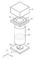
次に図面を参照して本発明の実施の形態にかかる投影光学系を投影露光装置に適用した例を示す。図1は本発明の実施の形態にかかる投影光学系を逐次露光型の投影露光装置に適用した例を示す斜視図であり、図2は本発明の実施の形態にかかる投影光学系を走査型露光装置に適用した例を示す斜視図である。
【0030】
これら図1および図2の投影露光装置は、ともに集積回路素子や液晶パネルなどのデバイスの回路パターンを形成する際の露光工程に用いられる。
まず、図1の例では、投影光学系PLの物体面には、所定の回路パターンが描かれた投影原板としてのレチクルR(第1物体)が配置されており、投影光学系PLの像面には基板としてのウエハW(第2物体)が配置されている。ここで、レチクルRはレチクルステージRSに保持されており、ウエハWは少なくとも図中XY方向に可動なウエハステージWSに保持されている。また、レチクルRの上方(Z方向側)には、紫外域の露光光によってマスクMの照明領域IAを均一に照明するための照明光学装置ILが配置されている。この実施の形態において、照明光学装置ILは、i線(λ=365nm)の紫外域の光を供給するものである。
【0031】
以上の構成により、照明光学装置ILから供給される紫外域の露光光は、レチクルR上の照明領域IAを均一に照明する。このレチクルRを通過した露光光は、投影光学系PLの開口絞りASの位置に光源像を形成する。すなわち、レチクルRは照明光学装置ILによってケーラー照明されている。そして、ウエハW上の露光領域EAには、レチクルRの照明領域IA内の像が形成され、これにより、ウエハWにはレチクルRの回路パターンが転写される。
【0032】
次に、図2の例では、レチクルRを保持するレチクルステージRSと、ウエハWを保持するウエハステージWSとが、露光中において互いに逆方向へ走査する点が図1の例とは異なっている。これにより、ウエハWには、レチクルR上の回路パターンの像が走査露光される。
以上の図1および図2の実施の形態では、投影光学系PLは、第1物体側(マスクM)側および第2物体側(プレートP側)において、実質的にテレセントリックとなっており、縮小倍率を有するものである。
【0033】
【実施例】
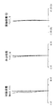
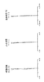
次に、図3〜図14を参照して本発明にかかる投影光学系の実施例について説明する。ここで、図3、図6、図9及び図12はそれぞれ第1〜第4実施例の投影光学系のレンズ断面図であり、図4、図7、図10及び図13はそれぞれ第1〜第4実施例の投影光学系の縦収差図、そして、図5、図8、図11及び図14はそれぞれ第1〜第4実施例の投影光学系の横収差図である。
[第1実施例]
図3において、第1実施例の投影光学系は、第1物体(レチクルR)側から順に、正屈折力の第1レンズ群G1と、負屈折力の第2レンズ群G2と、正屈折力の第3レンズ群G3と、負屈折力の第4レンズ群G4と、正屈折力の第5レンズ群G5とから構成される。
【0034】
第1レンズ群G1は、第1物体側から順に、両凸形状の正レンズL11、両凹形状の負レンズL12、両凸形状の2枚の正レンズL13,L14、第1物体側に凸面を向けた平凸形状の正レンズL15及び第2物体側に凹面を向けた平凹形状の負レンズL16から構成されている。この第1レンズ群G1においては、両凸形状の2枚の正レンズL13,L14が正屈折力の部分群G1pを構成している。
【0035】
第2レンズ群G2は、第1物体側から順に、両凸形状の正レンズL21、第2物体側に凹面を向けた平凹形状の負レンズL22、両凹形状の負レンズL23及び第1物体側に凹面を向けた平凹形状の負レンズL24から構成されている。第2レンズ群G2においては、3枚の負レンズL22〜L24が負屈折力の部分群G2nを構成している。
【0036】
第3レンズ群G3は、第1物体側から順に、第1物体側に凹面を向けた形状の正レンズL31、第1物体側に凹面を向けたメニスカス形状の負レンズL32、第1物体側に凹面を向けたメニスカス形状の正レンズL33、両凸形状の2枚の正レンズL34,L35、第1物体側に凸面を向けたメニスカス形状に正レンズL36から構成されている、ここで、第3レンズ群G3においては、3枚の正レンズL33〜L35が正屈折力の部分群G3pを構成している。
【0037】
第4レンズ群G4は、第1物体側から順に、第1物体側に凸面を向けたメニスカス形状のレンズL41、第1物体側に凸面を向けたメニスカス形状の負レンズL42、両凹形状の負レンズL43、第1物体側に凹面を向けたメニスカス形状の負レンズL44及び第2物体側に凸面を向けたメニスカス形状の正レンズL45から構成される。第4レンズ群G4においては、3枚の負レンズL42〜L44が負屈折力の部分群G4nを構成している。
【0038】
第5レンズ群G5は、第1物体側から順に、第1物体側に凹面を向けたメニスカス形状の正レンズL51、両凸形状の正レンズL52、第1物体側に凹面N1を向けたメニスカス形状の負レンズL53、第2物体側に凹面N2を向けたメニスカス形状の負レンズL54、両凸形状の正レンズL55、第1物体側に凸面を向けたメニスカス形状の3枚の正レンズL56〜L58、第2物体側に凹面N3を向けたメニスカス形状の負レンズL59及び第2物体側に凹面を向けた形状のメニスカス形状の正レンズG5gから構成されている。ここで、第5レンズ群G5では、正レンズL51,L52、負レンズL53,L54及び正レンズL55〜L57が正屈折力の部分群G5pを構成している。
【0039】
なお、第1実施例の投影光学系においては、開口絞りASは、第4レンズ群G4と第5レンズ群G5との間に配置されている。
[第2実施例]
図6において、第2実施例の投影光学系は、第1物体(レチクルR)側から順に、正屈折力の第1レンズ群G1と、負屈折力の第2レンズ群G2と、正屈折力の第3レンズ群G3と、負屈折力の第4レンズ群G4と、正屈折力の第5レンズ群G5とから構成される。
【0040】
第1レンズ群G1は、第1物体側から順に、両凸形状の正レンズL11、両凹形状の負レンズL12、両凸形状の2枚の正レンズL13,L14及び第2物体側に凹面を向けたメニスカス形状の負レンズL15から構成されている。第1レンズ群G1においては、2枚の正レンズL13,L14が正屈折力の部分群G1pを構成している。
第2レンズ群G2は、第1物体側から順に、両凸形状の正レンズL21、第2物体側に凹面を向けた形状の負レンズL22、両凹形状の負レンズL23及び第1物体側に凹面を向けた平凹形状の負レンズL24から構成されている。ここで、第2レンズ群G2では、3枚の負レンズL22〜L24が負屈折力の部分群G2nを構成している。
【0041】
第3レンズ群G3は、第1物体側から順に、第1物体側に凹面を向けたメニスカス形状の正レンズL31、第1物体側に凹面を向けたメニスカス形状の負レンズL32、第1物体側に凹面を向けたメニスカス形状の正レンズL33、両凸形状の正レンズL34及び第1物体側に凸面を向けたメニスカス形状の正レンズL35から構成されている。第3レンズ群においては、3枚の正レンズL33〜L35が正屈折力の部分群G3pを構成している。
【0042】
第4レンズ群G4は、第1物体側から順に、第1物体側に凸面を向けたメニスカス形状の正レンズL41、第1物体側に凸面を向けたメニスカス形状の負レンズL42、両凹形状の負レンズL43、第1物体側に凹面を向けたメニスカス形状の負レンズL44及び第2物体側に凸面を向けたメニスカス形状の正レンズL45から構成される。第4レンズ群G4においては、3枚の負レンズL42〜L44が負屈折力の部分群G4nを構成している。
【0043】
第5レンズ群G5は、第1物体側から順に、第1物体側に凹面を向けたメニスカス形状の正レンズL51、両凸形状の正レンズL52、第1物体側に凹面N1を向けたメニスカス形状の負レンズL53、第2物体側に凹面N2を向けたメニスカス形状の負レンズL54、両凸形状の正レンズL55、第1物体側に凸面を向けたメニスカス形状の3枚の正レンズL56〜L58、第2物体側に凹面N3を向けたメニスカス形状の負レンズL59及び第2物体側に凹面を向けた形状のメニスカス形状の正レンズG5gから構成されている。ここで、第5レンズ群G5では、正レンズL51,L52、負レンズL53,L54及び正レンズL55〜L57が正屈折力の部分群G5pを構成している。
【0044】
なお、第2実施例の投影光学系においては、開口絞りASは、第4レンズ群G4と第5レンズ群G5との間に配置されている。
[第3実施例]
図9において、第3実施例の投影光学系は、第1物体(レチクルR)側から順に、正屈折力の第1レンズ群G1と、負屈折力の第2レンズ群G2と、正屈折力の第3レンズ群G3と、負屈折力の第4レンズ群G4と、正屈折力の第5レンズ群G5とから構成される。
【0045】
第1レンズ群G1は、第1物体側から順に、第1物体側に凸面を向けたメニスカス形状の負レンズL11、両凸形状の3枚の正レンズL12〜L14及び第2物体側に凹面を向けた平凹形状の負レンズL15から構成されている。第1レンズ群G1では、2枚の正レンズL12,L13が正屈折力の部分群G1pを構成している。
第2レンズ群G2は、第1物体側から順に、両凸形状の正レンズL21、第2物体側に凹面を向けた平凹形状の負レンズL22、両凹形状の負レンズL23及び第1物体側に凹面を向けたメニスカス形状の負レンズL24から構成されている。第2レンズ群G2においては、3枚の負レンズL22〜L24が負屈折力の部分群G2nを構成している。
【0046】
第3レンズ群G3は、第1物体側から順に、第1物体側に凹面を向けたメニスカス形状の2枚の正レンズL31,L32及び両凸形状の3枚の正レンズL33〜L35から構成されている。ここで、第3レンズ群G3においては、3枚の正レンズL33〜L35が正屈折力の部分群G3pを構成している。
第4レンズ群G4は、第1物体側から順に、第1物体側に凸面を向けたメニスカス形状の正レンズL41、第1物体側に凸面を向けたメニスカス形状の負レンズL42、両凹形状の負レンズL43、第1物体側に凹面を向けた平凹形状の負レンズL44及び第2物体側に凸面を向けたメニスカス形状の正レンズL45から構成される。第4レンズ群G4においては、3枚の負レンズL42〜L44が負屈折力の部分群G4nを構成している。
【0047】
第5レンズ群G5は、第1物体側から順に、第1物体側に凹面を向けたメニスカス形状の正レンズL51、両凸形状の2枚の正レンズL52,L53、第1物体側向けられた凹面N1と第2物体側に向けられた凹面N2を持つ両凹形状の負レンズL54、両凸形状の正レンズL55、第1物体側に凸面を向けたメニスカス形状の3枚の正レンズL56〜L58、第2物体側に凹面N3を向けたメニスカス形状の負レンズL59及び第2物体側に凹面を向けた形状のメニスカス形状の正レンズG5gから構成されている。ここで、第5レンズ群G5では、正レンズL51〜L53、負レンズL54及び正レンズL55〜L57が正屈折力の部分群G5pを構成している。
【0048】
なお、第3実施例の投影光学系においては、開口絞りASは、第4レンズ群G4と第5レンズ群G5との間に配置されている。
[第4実施例]
図12において、第4実施例の投影光学系は、第1物体(レチクルR)側から順に、正屈折力の第1レンズ群G1と、負屈折力の第2レンズ群G2と、正屈折力の第3レンズ群G3と、負屈折力の第4レンズ群G4と、正屈折力の第5レンズ群G5とから構成される。
【0049】
第1レンズ群G1は、第1物体側から順に、両凸形状の正レンズL11、両凹形状の負レンズL12、両凸形状の2枚の正レンズL13,L14、第1物体側に凸面を向けた平凸形状の正レンズL15及び第2物体側に凹面を向けた平凹形状の負レンズL16から構成されている。この第1レンズ群G1においては、両凸形状の2枚の正レンズL13,L14が正屈折力の部分群G1pを構成している。
【0050】
第2レンズ群G2は、第1物体側から順に、両凸形状の正レンズL21、第2物体側に凹面を向けた平凹形状の負レンズL22、両凹形状の負レンズL23及び第1物体側に凹面を向けた平凹形状の負レンズL24から構成されている。第2レンズ群G2においては、3枚の負レンズL22〜L24が負屈折力の部分群G2nを構成している。
【0051】
第3レンズ群G3は、第1物体側から順に、第2物体側に凸面を向けた形状の正レンズL31、第1物体側に凹面を向けたメニスカス形状の負レンズL32、第1物体側に凹面を向けたメニスカス形状の正レンズL33、両凸形状の2枚の正レンズL34,L35、第1物体側に凸面を向けたメニスカス形状に正レンズL36から構成されている、ここで、第3レンズ群G3においては、3枚の正レンズL33〜L35が正屈折力の部分群G3pを構成している。
【0052】
第4レンズ群G4は、第1物体側から順に、第1物体側に凸面を向けたメニスカス形状の正レンズL41、第1物体側に凸面を向けたメニスカス形状の負レンズL42、両凹形状の負レンズL43、第1物体側に凹面を向けたメニスカス形状の負レンズL44及び第2物体側に凸面を向けたメニスカス形状の正レンズL45から構成される。第4レンズ群G4においては、3枚の負レンズL42〜L44が負屈折力の部分群G4nを構成している。
【0053】
第5レンズ群G5は、第1物体側から順に、第1物体側に凹面を向けたメニスカス形状の正レンズL51、両凸形状の正レンズL52、第1物体側に凹面N1を向けたメニスカス形状の負レンズL53、第2物体側に凹面N2を向けたメニスカス形状の負レンズL54、両凸形状の正レンズL55、第1物体側に凸面を向けたメニスカス形状の3枚の正レンズL56〜L58、第2物体側に凹面N3を向けたメニスカス形状の負レンズL59及び第2物体側に凹面を向けた形状のメニスカス形状の正レンズG5gから構成されている。ここで、第5レンズ群G5では、正レンズL51,L52、負レンズL53,L54及び正レンズL55〜L57が正屈折力の部分群G5pを構成している。
【0054】
なお、第4実施例の投影光学系においては、開口絞りASは、第4レンズ群G4と第5レンズ群G5との間に配置されている。
さて、以下に示す表1〜表8に数値実施例の諸元の値並びに条件対応数値を掲げる。
【0055】
但し、各表において、左端の数字は第1物体側(レチクルR側)からの順序を表し、rはレンズ面の曲率半径、dはレンズ面間隔、nは365.0nmにおける屈折率、d0は第1物体(レチクルR)から第1レンズ群G1の最も第1物体側(レチクルR側)のレンズ面(第1レンズ面)までの距離、WDは第5レンズ群G5の最も第2物体側(ウエハW側)のレンズ面から第2物体面(ウエハW面)までの距離、βは投影光学系の投影倍率、NAは投影光学系の第2物体側での開口数、φEXは第2物体面(プレートP面)における露光領域の半径、Lは物像間距離(第1物体(レチクルR)から第2物体(ウエハW)までの距離)、f1は第1レンズ群G1中の部分群G1pの焦点距離、f2は第2レンズ群G2中の部分群G2nの焦点距離、f3は第3レンズ群G3中の部分群G3pの焦点距離、f4は第4レンズ群G4中の部分群G4nの焦点距離、f5pは第5レンズ群G5中の部分群G5pの焦点距離である。また、各表において、f5gは第5レンズ群中の正レンズG5gの焦点距離、R5gは第5レンズ群中の正レンズG5gの第2物体側(ウエハW側)の凹面の曲率半径、Rn1は第5レンズ群G5中の第1物体側(レチクルR側)に向けられた第1の凹面N1の曲率半径、Rn2は第5レンズ群G5中の第2物体側(ウエハW側)に向けられた第2の凹面N2の曲率半径、Rn3は第5レンズ群G5中の第2物体側に向けられて第2の凹面N2よりも第2物体側に位置する第3の凹面N3の曲率半径、Rp1は第2レンズ群G2中の正レンズの第2物体側(ウエハW側)に向けられた面の曲率半径である。
【0056】
【表1】

【表2】
【表3】
【表4】
【表5】
【表6】
【表7】
【表8】
【0064】
また、図4、図7、図10及び図13はそれぞれ第1〜第4実施例の投影光学系の縦収差図を示している。そして、図5、図8、図11及び図14はそれぞれ第1〜第4実施例の投影光学系の子午方向(タンジェンシャル方向)及び球欠方向(サジタル方向)における横収差図を示している。
ここで、各収差図において、NAは投影光学系の開口数、Yは像高を示しており、また、非点収差図中において、点線は子午的像面(タンジェンシャル像面)、実線は球欠的像面(サジタル像面)を示している。
【0065】
各収差図の比較より、各実施例とも諸収差がバランス良く補正され、特に広い露光領域の全てにおいて諸収差が良好に補正されていることが理解される。
なお、以上の各実施例では、光源としてi線の紫外光を供給するものを用いた例を示したがこれに限ることなく、193nm,248.8nm の光を供給するエキシマレーザ等の極紫外光源や、g線(435.8nm)やh線(404.7nm)の光を供給する水銀アークランプ、さらにはそれ以外の紫外領域の光を供給する光源を用いたものにも応用し得ることは言うまでもない。
【0066】
【発明の効果】
以上の通り、本発明によれば、大きな開口数と広い露光領域とを確保しつつ両側テレセントリックとしながらも、諸収差、特にディストーションを極めて良好に補正し得る高性能な投影光学系を実現できる。
そして、本発明にかかる投影光学系を投影露光装置に適用すれば、極めて微細な回路パターンをウエハ上の広い露光領域に形成することができる効果を奏する。
【図面の簡単な説明】
【図1】本発明にかかる投影光学系を一括露光型の投影露光装置に適用した例を概略的に示す斜視図である。
【図2】本発明にかかる投影光学系を走査露光型の投影露光装置に適用した例を概略的に示す斜視図である。
【図3】第1実施例の投影光学系のレンズ構成図である。
【図4】第1実施例の投影光学系による縦収差図である。
【図5】第1実施例の投影光学系による横収差図である。
【図6】第2実施例の投影光学系のレンズ構成図である。
【図7】第2実施例の投影光学系による縦収差図である。
【図8】第2実施例の投影光学系による横収差図である。
【図9】第3実施例の投影光学系のレンズ構成図である。
【図10】第3実施例の投影光学系による縦収差図である。
【図11】第3実施例の投影光学系による横収差図である。
【図12】第4実施例の投影光学系のレンズ構成図である。
【図13】第4実施例の投影光学系による縦収差図である。
【図14】第4実施例の投影光学系による横収差図である。
【符号の説明】
G1:第1レンズ群、
G2:第2レンズ群、
G3:第3レンズ群、
G4:第4レンズ群、
G5:第5レンズ群、
G1p:第1レンズ群中の部分群、
G2n:第2レンズ群中の部分群、
G3p:第3レンズ群中の部分群、
G4n:第4レンズ群中の部分群、
G5p:第5レンズ群中の部分群、
G5g:第5レンズ群中の正レンズ、[0001]
[Industrial application fields]
The present invention relates to a projection optical system for projecting a pattern of a first object onto a substrate or the like as a second object, and particularly to a semiconductor or liquid crystal formed on a reticle (mask) as a first object. The present invention relates to a projection optical system suitable for projecting and exposing a pattern for use on a substrate (wafer, plate, etc.) as a second object.
[0002]
[Prior art]
As the pattern of an integrated circuit is further miniaturized, the performance required for a projection optical system used for printing a wafer is becoming stricter. Under such circumstances, to improve the resolving power of the projection optical system, it is conceivable to shorten the exposure wavelength λ or increase the numerical aperture (NA) of the projection optical system.
[0003]
In recent years, in order to cope with the miniaturization of transfer patterns, the light source for exposure mainly emits light having an exposure wavelength of g-line (436 nm) to light having an exposure wavelength of i-line (365 nm). Further, a light source that emits light having a shorter wavelength, for example, an excimer laser (KrF: 248 nm, ArF: 193 nm) is about to be used.
[0004]
Then, there has been proposed a projection optical system for projecting and exposing a pattern on a reticle onto a wafer with light of various exposure wavelengths as described above.
In the projection optical system, it is required to reduce image distortion along with improvement in resolution. Here, the image distortion is not only due to distortion (distortion aberration) caused by the projection optical system, but also due to warpage of the wafer baked on the image side of the projection optical system, circuit pattern on the object side of the projection optical system, etc. Is due to the warping of the reticle on which is drawn.
[0005]
In recent years, the transfer pattern has been further miniaturized, and the demand for reducing image distortion has become more severe.
Therefore, in order to reduce the influence on the image distortion due to the warpage of the wafer, a so-called image side telecentric optical system in which the exit pupil position on the image side of the projection optical system is located far has been used.
[0006]
On the other hand, to reduce image distortion due to reticle warpage, it is conceivable to use a so-called object-side telecentric optical system in which the entrance pupil position of the projection optical system is located far from the object plane. Proposals have been made to position the entrance pupil position relatively far from the object plane. Examples thereof include JP-A 63-118115, JP-A 4-157412, and JP-A 5-173065.
[0007]
[Problems to be solved by the invention]
Among the optical systems proposed in each of the above patent publications, a so-called double telecentric projection optical system is disclosed in which both the object side and the image side are telecentric.
However, in the double-sided telecentric projection optical system proposed in each of the above patent publications, the numerical aperture (NA) contributing to the resolving power is not sufficiently large, and further, correction of each aberration, particularly distortion, is not sufficient.
[0008]
The present invention has been made in view of the above-described problems, and has a high performance capable of correcting various aberrations, particularly distortion, very well while maintaining both a large numerical aperture and a wide exposure area while being both-side telecentric. The object is to provide a projection optical system.
[0009]
[Means for Solving the Problems]
In order to achieve the above-described object, a projection optical system according to the present invention forms an image of a first object on a second object, and sequentially from the first object side,
A first lens group having positive refractive power and including three positive lenses;
A second lens group having negative refractive power and including three negative lenses and one positive lens;
A third lens group having positive refractive power and including three positive lenses and one negative lens;
A fourth lens group having negative refractive power and including three negative lenses;
A fifth lens group having positive refractive power and including six positive lenses and one negative lens;
The first lens group has a partial group G1p including at least two positive lenses,
The second lens group has a partial group G2n including at least three negative lenses,
The third lens group has a partial group G3p including at least three positive lenses,
The fourth lens group has a partial group G4n including at least three negative lenses,
The fifth lens group includes a partial group G5p including at least five positive lenses, and a positive lens G5g disposed closest to the second object side and having a concave surface facing the second object side,
The following conditions are satisfied.
[0010]
0.08 <f1 / L <0.25 (1)
0.03 <-f2 / L <0.1 (2)
0.08 <f3 / L <0.3 (3)
0.035 <-f4 / L <0.11 (4)
0.1 <f5p / L <0.25 (5)
0.07 <f5g / L <0.21 (6)
0.25 <R5g / L <0.83 (7)
However,
L: distance from the first object to the second object,
f1: focal length of the subgroup G1p in the first lens group,
f2: focal length of the subgroup G2n in the second lens group,
f3: focal length of the subgroup G3p in the third lens group,
f4: focal length of the subgroup G4n in the fourth lens group,
f5p: focal length of the subgroup G5p in the fifth lens group,
f5g: focal length of the positive lens G5g in the fifth lens group,
R5g: the radius of curvature of the concave surface on the second object side of the positive lens G5g in the fifth lens group,
It is.
[0011]
In the present invention, the fifth lens group preferably has a first concave surface N1 directed toward the first object side,
When the radius of curvature of the concave surface N1 is Rn1, it is preferable that the following condition is satisfied.
0.125 <-Rn1 / L <0.33 (8)
In a preferred aspect of the present invention, the fifth lens group includes at least four positive lenses that satisfy the following conditions.
[0012]
−10 <(r1 + r2) / (r1−r2) <− 0.1 (9)
However,
r1: radius of curvature of the first object side surface of at least four positive lenses;
r2: radius of curvature of the surface on the second object side of at least four positive lenses,
It is.
[0013]
According to a preferred aspect of the present invention, the fifth lens group includes a second concave surface N2 directed toward the second object side, and the second object located on the second object side relative to the second concave surface N2. And the third concave surface N3 directed to the side, and preferably satisfy the following conditions.
0.16 <Rn2 / L <0.38 (10)
0.055 <Rn3 / L <0.11 (11)
However,
Rn2: radius of curvature of the second concave surface N2,
Rn3: radius of curvature of the third concave surface N3,
It is.
[0014]
According to a preferred aspect of the present invention, the second lens group includes at least one positive lens, and when the radius of curvature of the surface of the positive lens facing the second object is Rp1, the following condition is satisfied. It is preferable to satisfy.
0.23 <-Rp1 / L <0.5 (12)
[0015]
DETAILED DESCRIPTION OF THE INVENTION
In the projection optical system according to the present invention having the above-described configuration, in order from the first object, the first lens group G1 having a positive refractive power, the second lens group G2 having a negative refractive power, and the positive refractive power. At least a third lens group G3 having negative refractive power, a fourth lens group G4 having negative refractive power, and a fifth lens group G5 having positive refractive power.
[0016]
Here, the first lens group G1 having a positive refractive power guides the telecentric light beam emitted from the first object to the second lens group and the subsequent lens groups, and generates positive distortion in advance. Negative distortion that occurs in the lens group disposed on the second object side of the group G1, particularly the second, fourth, and fifth lens groups is corrected.
[0017]
The third lens group G3 having a positive refractive power also has a role of generating positive distortion and correcting negative distortion generated in the second, fourth, and fifth lens groups G4 and G5. When viewed from the second object side, the third lens group G3 and the second lens group G2 constitute a telephoto system having positive and negative refractive power arrangements, which makes the entire projection lens system long. It has a function to prevent conversion.
[0018]
The second and fourth lens groups G2 and G4 having negative refractive power mainly contribute to correction of Petzval sum and have a function of achieving a flat image surface.
The fifth lens group G5 having a positive refractive power has a role of guiding a light beam onto the second object and forming an image while avoiding the occurrence of spherical aberration as much as possible.
Next, conditional expressions will be described. As described above, the projection optical system according to the present invention is configured to satisfy the following conditions (1) to (7).
[0019]
0.08 <f1 / L <0.25 (1)
0.03 <-f2 / L <0.1 (2)
0.08 <f3 / L <0.3 (3)
0.035 <-f4 / L <0.11 (4)
0.1 <f5p / L <0.25 (5)
0.07 <f5g / L <0.21 (6)
0.25 <R5g / L <0.83 (7)
However,
L: distance from the first object to the second object,
f1: focal length of the subgroup G1p in the first lens group,
f2: focal length of the subgroup G2n in the second lens group,
f3: focal length of the subgroup G3p in the third lens group,
f4: focal length of the subgroup G4n in the fourth lens group,
f5p: focal length of the subgroup G5p in the fifth lens group,
f5g: focal length of the positive lens G5g in the fifth lens group,
R5g: the radius of curvature of the concave surface on the second object side of the positive lens G5g in the fifth lens group,
It is.
Condition (1) defines an appropriate refractive power of the subgroup G1p that bears the main refractive power in the first lens group G1. Exceeding the upper limit of the condition (1) is not preferable because negative distortion generated in the second, fourth, and fifth lens groups cannot be corrected. Further, exceeding the lower limit of the condition (1) is not preferable because it causes high-order positive distortion.
[0020]
Condition (2) defines the appropriate negative refractive power of the subgroup G2n that bears the main negative refractive power in the second lens G2. If the upper limit of the condition (2) is exceeded, the Petzval sum will be insufficiently corrected, and the flatness of the image will be deteriorated. Further, if the lower limit of the condition (2) is exceeded, the occurrence of positive distortion increases, and it becomes difficult to correct this large positive distortion with only the first and third lens groups.
[0021]
Condition (3) defines an appropriate positive refractive power of the partial group G3p that bears the main refractive power in the third lens group G3. If the upper limit of condition (3) is exceeded, the tele ratio of the telephoto system formed with the second lens group will increase, leading to an increase in the length of the system, and the amount of positive distortion in the third lens group G3 will be small. Since negative distortion generated in the second, fourth, and fifth lens groups cannot be corrected satisfactorily, it is not preferable. If the lower limit of the condition (3) is exceeded, high-order spherical aberration occurs and it becomes impossible to obtain good imaging performance, which is not preferable.
[0022]
Condition (4) defines an appropriate refractive power of the subgroup G4n that bears the main negative refractive power in the fourth lens group G4. Exceeding the upper limit of the condition (4) is not preferable because the Petzval sum is insufficiently corrected and the flatness of the image is deteriorated. If the lower limit of the condition (4) is exceeded, high-order spherical aberration will be caused and image contrast will be deteriorated.
[0023]
Condition (5) defines an appropriate refractive power of the subgroup G5p that bears the main positive refractive power in the fifth lens group G5. Here, exceeding the upper limit of the condition (5) is not preferable because the positive refractive power of the entire fifth lens group G5 becomes too weak, resulting in an increase in the length of the entire projection lens system. Further, if the lower limit of the condition (5) is exceeded, negative distortion and negative spherical aberration increase, which causes an image deterioration.
[0024]
Condition (6) defines an appropriate refractive power of the positive lens G5g disposed in the fifth lens group G5 on the second object side of the partial group G5p. When the upper limit of the condition (6) is exceeded, the refractive power of the positive lens G5g becomes too weak, and a burden is placed on the lens disposed on the first object side of the positive lens G5g in the fifth lens group G5. This is not preferable because it causes deterioration of spherical aberration and an increase in the length of the projection lens system. Further, when the lower limit of the condition (6) is exceeded, negative distortion and negative spherical aberration are increased and the image is deteriorated.
[0025]
Condition (7) defines an appropriate range for the object-image distance of the radius of curvature of the concave surface directed toward the second object side of the positive lens G5g arranged closest to the second object side in the fifth lens group G5. Is. On the lens surface on the second object side of the positive lens G5g, the concave surface is directed toward the second object side, thereby suppressing the occurrence of negative spherical aberration as much as possible with respect to the high numerical aperture light beam. Here, exceeding the upper limit of the condition (7) is not preferable because high-order negative spherical aberration occurs on the concave surface, and the projection lens system cannot be increased in numerical aperture. Further, if the lower limit of the condition (7) is exceeded, the light beam is excessively diverged by this concave surface, so that the light cannot be bent efficiently, and the entire projection lens system is lengthened, which is not preferable. Further, in this case, since a load is applied to the other positive lenses in the fifth lens group G5, the spherical aberration is also deteriorated, which is not preferable.
[0026]
In the present invention, the fifth lens group G5 preferably has a first concave surface N1 directed toward the first object side, and the radius of curvature Rn1 of the concave surface N1 satisfies the following condition (8). preferable.
0.125 <-Rn1 / L <0.33 (8)
The first concave surface N1 directed to the first object side in the fifth lens group G5 mainly has a function of correcting negative spherical aberration generated from the positive lens in the fifth lens group G5. In the condition (8), the ratio of the appropriate radius of curvature of the first concave surface N1 with respect to the distance between the object images is defined. Here, if the upper limit of the condition (8) is exceeded, the negative spherical aberration generated from the positive lens becomes insufficiently corrected, which is not preferable. If the lower limit of the condition (8) is exceeded, the spherical aberration is overcorrected, and high-order positive spherical aberration occurs, which is not preferable.
[0027]
In the present invention, it is preferable that the fifth lens group G5 includes at least four positive lenses that satisfy the following conditions.
−10 <(r1 + r2) / (r1−r2) <− 0.1 (9)
However,
r1: radius of curvature of the first object side surface of at least four positive lenses;
r2: radius of curvature of the surface on the second object side of at least four positive lenses,
It is.
The condition (9) defines the shape of the positive lens included in the fifth lens group G5. Here, when the lens shape exceeds the upper limit of the condition (9), negative spherical aberration occurs greatly, making correction difficult. When the lens shape exceeds the lower limit of the condition (9), the lens shape is negative. Therefore, it is difficult to correct the distortion. Since the fifth lens group G5 is arranged closer to the second object than the other lens groups, a light beam having a high numerical aperture passes therethrough. Therefore, in the fifth lens group G5, when the number of positive lenses satisfying the above condition (9) is less than four, good correction of spherical aberration at a high numerical aperture and good distortion over a wide exposure area It is not preferable because it cannot be compatible with the correction.
In the present invention, the fifth lens group G5 is a second concave surface N2 directed toward the second object side, and is located on the second object side and directed toward the second object side with respect to the second concave surface N2. It is preferable that the second and third concave surfaces N2 and N3 satisfy the following conditions.
[0028]
0.16 <Rn2 / L <0.38 (10)
0.055 <Rn3 / L <0.11 (11)
However,
Rn2: radius of curvature of the second concave surface N2,
Rn3: radius of curvature of the third concave surface N3,
It is.
In the second concave surface N2 and the third concave surface N3 directed to the second object side in the fifth lens group G5, negative spherical aberration and negative distortion mainly generated from the positive lens in the fifth lens group G5. It has a function to correct. In the above conditions (10) and (11), appropriate ratios of the curvature radii of the second and third concave surfaces N2 and N3 with respect to the distance between the object images are respectively defined. Here, if the upper limits of the conditions (10) and (11) are exceeded, negative spherical aberration and negative distortion remain, which is not preferable. If the lower limits of the conditions (10) and (11) are exceeded, particularly spherical aberration will occur. This is not preferable because overcorrection causes higher order spherical aberration.
[0029]
In the present invention, it is preferable that the following condition is satisfied when the radius of curvature of the surface facing the second object side of the positive lens in the second lens group G2 is Rp1.
0.23 <-Rp1 / L <0.5 (12)
Condition (12) defines the radius of curvature of the convex surface directed toward the second object side of the positive lens in the second lens group G2 for the entire system. This convex surface plays a role of correcting negative distortion generated in the second, fourth, and fifth lens groups G2, G4, and G5. Here, when the upper limit of the condition (12) is exceeded, distortion is not sufficiently corrected, and negative distortion remains, which is not preferable. If the lower limit of the condition (12) is exceeded, the distortion will be overcorrected and positive high-order distortion will occur, which is not preferable.
Next, an example in which the projection optical system according to the embodiment of the present invention is applied to a projection exposure apparatus will be described with reference to the drawings. FIG. 1 is a perspective view showing an example in which a projection optical system according to an embodiment of the present invention is applied to a sequential exposure type projection exposure apparatus, and FIG. 2 is a scanning type projection optical system according to an embodiment of the present invention. It is a perspective view which shows the example applied to the exposure apparatus.
[0030]
1 and 2 are both used in an exposure process when forming a circuit pattern of a device such as an integrated circuit element or a liquid crystal panel.
First, in the example of FIG. 1, a reticle R (first object) as a projection original plate on which a predetermined circuit pattern is drawn is arranged on the object plane of the projection optical system PL, and the image plane of the projection optical system PL A wafer W (second object) as a substrate is disposed on the substrate. Here, reticle R is held on reticle stage RS, and wafer W is held on wafer stage WS that is movable at least in the XY directions in the drawing. In addition, an illumination optical device IL for uniformly illuminating the illumination area IA of the mask M with ultraviolet exposure light is disposed above the reticle R (Z direction side). In this embodiment, the illumination optical device IL supplies i-line (λ = 365 nm) ultraviolet light.
[0031]
With the above configuration, the exposure light in the ultraviolet region supplied from the illumination optical device IL uniformly illuminates the illumination region IA on the reticle R. The exposure light that has passed through the reticle R forms a light source image at the position of the aperture stop AS of the projection optical system PL. That is, the reticle R is Koehler illuminated by the illumination optical device IL. Then, an image in the illumination area IA of the reticle R is formed in the exposure area EA on the wafer W, whereby the circuit pattern of the reticle R is transferred to the wafer W.
[0032]
Next, the example of FIG. 2 is different from the example of FIG. 1 in that the reticle stage RS that holds the reticle R and the wafer stage WS that holds the wafer W scan in opposite directions during exposure. . As a result, the image of the circuit pattern on the reticle R is scanned and exposed on the wafer W.
In the embodiment shown in FIGS. 1 and 2, the projection optical system PL is substantially telecentric on the first object side (mask M) side and the second object side (plate P side). It has a magnification.
[0033]
【Example】
Next, an embodiment of the projection optical system according to the present invention will be described with reference to FIGS. Here, FIG. 3, FIG. 6, FIG. 9 and FIG. 12 are lens sectional views of the projection optical systems of the first to fourth embodiments, respectively, and FIG. 4, FIG. 7, FIG. Longitudinal aberration diagrams of the projection optical system of the fourth example, and FIGS. 5, 8, 11, and 14 are lateral aberration diagrams of the projection optical system of the first to fourth examples, respectively.
[First embodiment]
In FIG. 3, the projection optical system of the first example includes, in order from the first object (reticle R) side, a first lens group G1 having a positive refractive power, a second lens group G2 having a negative refractive power, and a positive refractive power. The third lens group G3, a fourth lens group G4 having negative refractive power, and a fifth lens group G5 having positive refractive power.
[0034]
The first lens group G1, in order from the first object side, has a biconvex positive lens L11, a biconcave negative lens L12, two biconvex positive lenses L13 and L14, and a convex surface on the first object side. And a plano-convex positive lens L15 and a plano-concave negative lens L16 having a concave surface facing the second object side. In the first lens group G1, two biconvex positive lenses L13 and L14 form a positive refractive power subgroup G1p.
[0035]
The second lens group G2 includes, in order from the first object side, a biconvex positive lens L21, a plano-concave negative lens L22 with a concave surface facing the second object side, a biconcave negative lens L23, and the first object. It consists of a plano-concave negative lens L24 with a concave surface facing the side. In the second lens group G2, the three negative lenses L22 to L24 constitute a partial group G2n having a negative refractive power.
[0036]
The third lens group G3 includes, in order from the first object side, a positive lens L31 having a concave surface facing the first object side, a meniscus negative lens L32 having a concave surface facing the first object side, and a first object side. Consists of a meniscus positive lens L33 with a concave surface, two biconvex positive lenses L34 and L35, and a meniscus positive lens L36 with a convex surface facing the first object. In the lens group G3, the three positive lenses L33 to L35 constitute a partial group G3p having a positive refractive power.
[0037]
The fourth lens group G4 includes, in order from the first object side, a meniscus lens L41 having a convex surface facing the first object side, a meniscus negative lens L42 having a convex surface facing the first object side, and a biconcave negative lens. The lens L43 includes a meniscus negative lens L44 having a concave surface facing the first object side, and a meniscus positive lens L45 having a convex surface facing the second object side. In the fourth lens group G4, the three negative lenses L42 to L44 constitute a negative refractive power subgroup G4n.
[0038]
The fifth lens group G5 includes, in order from the first object side, a meniscus positive lens L51 having a concave surface facing the first object side, a biconvex positive lens L52, and a meniscus shape having a concave surface N1 facing the first object side. Negative lens L53, meniscus negative lens L54 with the concave surface N2 facing the second object side, biconvex positive lens L55, and three meniscus positive lenses L56 to L58 with the convex surface facing the first object side , A negative meniscus lens L59 having a concave surface N3 facing the second object side, and a positive meniscus lens G5g having a concave surface facing the second object side. Here, in the fifth lens group G5, the positive lenses L51 and L52, the negative lenses L53 and L54, and the positive lenses L55 to L57 constitute a partial group G5p having a positive refractive power.
[0039]
In the projection optical system of the first example, the aperture stop AS is disposed between the fourth lens group G4 and the fifth lens group G5.
[Second Embodiment]
In FIG. 6, the projection optical system of the second example includes a first lens group G1 having a positive refractive power, a second lens group G2 having a negative refractive power, and a positive refractive power in order from the first object (reticle R) side. The third lens group G3, a fourth lens group G4 having negative refractive power, and a fifth lens group G5 having positive refractive power.
[0040]
The first lens group G1, in order from the first object side, has a biconvex positive lens L11, a biconcave negative lens L12, two biconvex positive lenses L13 and L14, and a concave surface on the second object side. It is composed of a meniscus negative lens L15 that is directed. In the first lens group G1, the two positive lenses L13 and L14 constitute a positive refractive power partial group G1p.
The second lens group G2 includes, in order from the first object side, a biconvex positive lens L21, a negative lens L22 having a concave surface facing the second object side, a biconcave negative lens L23, and a first object side. It is composed of a plano-concave negative lens L24 having a concave surface. Here, in the second lens group G2, the three negative lenses L22 to L24 form a partial group G2n having a negative refractive power.
[0041]
The third lens group G3 includes, in order from the first object side, a meniscus positive lens L31 having a concave surface facing the first object side, a meniscus negative lens L32 having a concave surface facing the first object side, and the first object side. The lens includes a meniscus positive lens L33 having a concave surface and a biconvex positive lens L34 and a meniscus positive lens L35 having a convex surface facing the first object. In the third lens group, the three positive lenses L33 to L35 constitute a partial group G3p having a positive refractive power.
[0042]
The fourth lens group G4 includes, in order from the first object side, a meniscus positive lens L41 having a convex surface facing the first object side, a meniscus negative lens L42 having a convex surface facing the first object side, and a biconcave shape. The lens includes a negative lens L43, a meniscus negative lens L44 having a concave surface facing the first object, and a meniscus positive lens L45 having a convex surface facing the second object. In the fourth lens group G4, the three negative lenses L42 to L44 constitute a negative refractive power subgroup G4n.
[0043]
The fifth lens group G5 includes, in order from the first object side, a meniscus positive lens L51 having a concave surface facing the first object side, a biconvex positive lens L52, and a meniscus shape having a concave surface N1 facing the first object side. Negative lens L53, meniscus negative lens L54 with the concave surface N2 facing the second object side, biconvex positive lens L55, and three meniscus positive lenses L56 to L58 with the convex surface facing the first object side , A negative meniscus lens L59 having a concave surface N3 facing the second object side, and a positive meniscus lens G5g having a concave surface facing the second object side. Here, in the fifth lens group G5, the positive lenses L51 and L52, the negative lenses L53 and L54, and the positive lenses L55 to L57 constitute a partial group G5p having a positive refractive power.
[0044]
In the projection optical system of the second example, the aperture stop AS is disposed between the fourth lens group G4 and the fifth lens group G5.
[Third embodiment]
In FIG. 9, the projection optical system according to the third example includes, in order from the first object (reticle R) side, a first lens group G1 having a positive refractive power, a second lens group G2 having a negative refractive power, and a positive refractive power. The third lens group G3, a fourth lens group G4 having negative refractive power, and a fifth lens group G5 having positive refractive power.
[0045]
The first lens group G1, in order from the first object side, has a meniscus negative lens L11 with a convex surface facing the first object side, three biconvex positive lenses L12 to L14, and a concave surface on the second object side. It is composed of a negative lens L15 having a plano-concave shape. In the first lens group G1, the two positive lenses L12 and L13 constitute a partial group G1p having a positive refractive power.
The second lens group G2 includes, in order from the first object side, a biconvex positive lens L21, a plano-concave negative lens L22 with a concave surface facing the second object side, a biconcave negative lens L23, and the first object. It is composed of a meniscus negative lens L24 having a concave surface on the side. In the second lens group G2, the three negative lenses L22 to L24 constitute a partial group G2n having a negative refractive power.
[0046]
The third lens group G3 includes, in order from the first object side, two meniscus positive lenses L31 and L32 having a concave surface facing the first object side, and three biconvex positive lenses L33 to L35. ing. Here, in the third lens group G3, the three positive lenses L33 to L35 constitute a partial group G3p having a positive refractive power.
The fourth lens group G4 includes, in order from the first object side, a meniscus positive lens L41 having a convex surface facing the first object side, a meniscus negative lens L42 having a convex surface facing the first object side, and a biconcave shape. The lens includes a negative lens L43, a plano-concave negative lens L44 having a concave surface facing the first object, and a meniscus positive lens L45 having a convex surface facing the second object. In the fourth lens group G4, the three negative lenses L42 to L44 constitute a negative refractive power subgroup G4n.
[0047]
In order from the first object side, the fifth lens group G5 has a meniscus positive lens L51 having a concave surface facing the first object side, two biconvex positive lenses L52 and L53, and the first object side. A biconcave negative lens L54 having a concave surface N1 and a concave surface N2 directed toward the second object side, a biconvex positive lens L55, and three meniscus positive lenses L56, with a convex surface facing the first object side L58, a meniscus negative lens L59 having a concave surface N3 facing the second object side, and a meniscus positive lens G5g having a concave surface facing the second object side. Here, in the fifth lens group G5, the positive lenses L51 to L53, the negative lens L54, and the positive lenses L55 to L57 constitute a partial group G5p having a positive refractive power.
[0048]
In the projection optical system of the third example, the aperture stop AS is disposed between the fourth lens group G4 and the fifth lens group G5.
[Fourth embodiment]
In FIG. 12, the projection optical system of the fourth example includes, in order from the first object (reticle R) side, a first lens group G1 having a positive refractive power, a second lens group G2 having a negative refractive power, and a positive refractive power. The third lens group G3, a fourth lens group G4 having negative refractive power, and a fifth lens group G5 having positive refractive power.
[0049]
The first lens group G1, in order from the first object side, has a biconvex positive lens L11, a biconcave negative lens L12, two biconvex positive lenses L13 and L14, and a convex surface on the first object side. And a plano-convex positive lens L15 and a plano-concave negative lens L16 having a concave surface facing the second object side. In the first lens group G1, two biconvex positive lenses L13 and L14 form a positive refractive power subgroup G1p.
[0050]
The second lens group G2 includes, in order from the first object side, a biconvex positive lens L21, a plano-concave negative lens L22 with a concave surface facing the second object side, a biconcave negative lens L23, and the first object. It consists of a plano-concave negative lens L24 with a concave surface facing the side. In the second lens group G2, the three negative lenses L22 to L24 constitute a partial group G2n having a negative refractive power.
[0051]
The third lens group G3 includes, in order from the first object side, a positive lens L31 having a convex surface facing the second object side, a meniscus negative lens L32 having a concave surface facing the first object side, and a first lens side facing the first object side. Consists of a meniscus positive lens L33 with a concave surface, two biconvex positive lenses L34 and L35, and a meniscus positive lens L36 with a convex surface facing the first object. In the lens group G3, the three positive lenses L33 to L35 constitute a partial group G3p having a positive refractive power.
[0052]
The fourth lens group G4 includes, in order from the first object side, a meniscus positive lens L41 having a convex surface facing the first object side, a meniscus negative lens L42 having a convex surface facing the first object side, and a biconcave shape. The lens includes a negative lens L43, a meniscus negative lens L44 having a concave surface facing the first object, and a meniscus positive lens L45 having a convex surface facing the second object. In the fourth lens group G4, the three negative lenses L42 to L44 constitute a negative refractive power subgroup G4n.
[0053]
The fifth lens group G5 includes, in order from the first object side, a meniscus positive lens L51 having a concave surface facing the first object side, a biconvex positive lens L52, and a meniscus shape having a concave surface N1 facing the first object side. Negative lens L53, meniscus negative lens L54 with the concave surface N2 facing the second object side, biconvex positive lens L55, and three meniscus positive lenses L56 to L58 with the convex surface facing the first object side , A negative meniscus lens L59 having a concave surface N3 facing the second object side, and a positive meniscus lens G5g having a concave surface facing the second object side. Here, in the fifth lens group G5, the positive lenses L51 and L52, the negative lenses L53 and L54, and the positive lenses L55 to L57 constitute a partial group G5p having a positive refractive power.
[0054]
In the projection optical system of the fourth example, the aperture stop AS is disposed between the fourth lens group G4 and the fifth lens group G5.
Tables 1 to 8 below show values of numerical values and numerical values corresponding to conditions in numerical examples.
[0055]
However, in each table, the leftmost number indicates the order from the first object side (reticle R side), r is the radius of curvature of the lens surface, d is the lens surface interval, n is the refractive index at 365.0 nm, and d0 is the first number. The distance from one object (reticle R) to the lens surface (first lens surface) closest to the first object side (reticle R side) of the first lens group G1, WD is the second object side (fifth object side of the fifth lens group G5). The distance from the lens surface on the wafer W side to the second object surface (wafer W surface), β is the projection magnification of the projection optical system, NA is the numerical aperture on the second object side of the projection optical system, and φEX is the second object The radius of the exposure area on the surface (plate P surface), L is the distance between the object images (distance from the first object (reticle R) to the second object (wafer W)), and f1 is a subgroup in the first lens group G1. The focal length of G1p, f2 is the focal length of the subgroup G2n in the second lens group G2, and f3 is the third. The focal length of the subgroup G3p in lens group G3, f4 is the focal length of the subgroup G4n in the fourth lens group G4, f5p is the focal length of the subgroup G5p in the fifth lens group G5. In each table, f5g is the focal length of the positive lens G5g in the fifth lens group, R5g is the radius of curvature of the concave surface on the second object side (wafer W side) of the positive lens G5g in the fifth lens group, and Rn1 is The curvature radius Rn2 of the first concave surface N1 directed to the first object side (reticle R side) in the fifth lens group G5 is directed to the second object side (wafer W side) in the fifth lens group G5. The radius of curvature of the second concave surface N2, Rn3 is directed toward the second object side in the fifth lens group G5, and the radius of curvature of the third concave surface N3 located on the second object side relative to the second concave surface N2, Rp1 is the radius of curvature of the surface of the positive lens in the second lens group G2 facing the second object side (wafer W side).
[0056]
[Table 1]
[Table 2]
[Table 3]
[Table 4]
[Table 5]
[Table 6]
[Table 7]
[Table 8]
[0064]
FIGS. 4, 7, 10 and 13 are longitudinal aberration diagrams of the projection optical systems of the first to fourth embodiments, respectively. 5, FIG. 8, FIG. 11 and FIG. 14 show transverse aberration diagrams in the meridional direction (tangential direction) and the spherical missing direction (sagittal direction) of the projection optical systems of the first to fourth embodiments, respectively. .
Here, in each aberration diagram, NA represents the numerical aperture of the projection optical system, Y represents the image height, and in the astigmatism diagram, the dotted line represents the meridian image plane (tangential image plane), and the solid line represents A spherical image plane (sagittal image plane) is shown.
[0065]
From the comparison of the respective aberration diagrams, it is understood that the various aberrations are corrected in a balanced manner in each example, and particularly, the various aberrations are well corrected in all the wide exposure regions.
In each of the above-described embodiments, an example in which an i-line ultraviolet light source is used as a light source has been shown. Needless to say, it can be applied to mercury arc lamps that supply g-line (435.8 nm) and h-line (404.7 nm) light, and other light sources that supply light in the ultraviolet region. .
[0066]
【The invention's effect】
As described above, according to the present invention, it is possible to realize a high-performance projection optical system that can correct various aberrations, particularly distortion, very well while ensuring a large numerical aperture and a wide exposure area and performing both-side telecentricity.
If the projection optical system according to the present invention is applied to a projection exposure apparatus, an extremely fine circuit pattern can be formed in a wide exposure region on the wafer.
[Brief description of the drawings]
FIG. 1 is a perspective view schematically showing an example in which a projection optical system according to the present invention is applied to a batch exposure type projection exposure apparatus.
FIG. 2 is a perspective view schematically showing an example in which the projection optical system according to the present invention is applied to a scanning exposure type projection exposure apparatus.
FIG. 3 is a lens configuration diagram of the projection optical system of the first example.
FIG. 4 is a longitudinal aberration diagram of the projection optical system according to the first example.
FIG. 5 is a lateral aberration diagram by the projection optical system of the first example.
FIG. 6 is a lens configuration diagram of the projection optical system of Example 2.
FIG. 7 is a longitudinal aberration diagram of the projection optical system of the second example.
FIG. 8 is a lateral aberration diagram due to the projection optical system of the second example.
FIG. 9 is a lens configuration diagram of the projection optical system of Example 3.
FIG. 10 is a longitudinal aberration diagram of the projection optical system according to the third example.
FIG. 11 is a lateral aberration diagram due to the projection optical system of the third example.
FIG. 12 is a lens configuration diagram of the projection optical system of Example 4.
FIG. 13 is a longitudinal aberration diagram of the projection optical system according to the fourth example.
FIG. 14 is a lateral aberration diagram by the projection optical system of the fourth example.
[Explanation of symbols]
G1: first lens group,
G2: second lens group,
G3: third lens group,
G4: fourth lens group,
G5: fifth lens group,
G1p: a subgroup in the first lens group,
G2n: a subgroup in the second lens group,
G3p: a subgroup in the third lens group,
G4n: a subgroup in the fourth lens group,
G5p: a subgroup in the fifth lens group,
G5g: positive lens in the fifth lens group,
Claims (17)
前記第1物体側から順に、
正の屈折力を有し、3枚の正レンズを含む第1レンズ群と、
負の屈折力を有し、3枚の負レンズと1枚の正レンズとを含む第2レンズ群と、
正の屈折力を有し、3枚の正レンズと1枚の負レンズとを含む第3レンズ群と、
負の屈折力を有し、3枚の負レンズを含む第4レンズ群と、
正の屈折力を有し、6枚の正レンズと1枚の負レンズとを含む第5レンズ群とを備え、
前記第1レンズ群は少なくとも2枚の正レンズを含む部分群G1pを有し、
前記第2レンズ群は少なくとも3枚の負レンズを含む部分群G2nを有し、
前記第3レンズ群は少なくとも3枚の正レンズを含む部分群G3pを有し、
前記第4レンズ群は少なくとも3枚の負レンズを含む部分群G4nを有し、
前記第5レンズ群は少なくとも5枚の正レンズを含む部分群G5pと最も第2物体側に配置されて第2物体側に凹面を向けた正レンズG5gとを有し、
以下の条件を満足することを特徴とする投影光学系。
0.08 < f1/L< 0.25
0.03 <-f2/L< 0.1
0.08 < f3/L< 0.3
0.035<-f4/L< 0.11
0.1 < f5p/L<0.25
0.07 < f5g/L<0.21
0.25 < R5g/L<0.83
但し、
L :前記第1物体から前記第2物体までの距離、
f1 :前記第1レンズ群中の部分群G1pの焦点距離、
f2 :前記第2レンズ群中の部分群G2nの焦点距離、
f3 :前記第3レンズ群中の部分群G3pの焦点距離、
f4 :前記第4レンズ群中の部分群G4nの焦点距離、
f5p:前記第5レンズ群中の部分群G5pの焦点距離、
f5g:前記第5レンズ群中の正レンズG5gの焦点距離、
R5g:前記第5レンズ群中の正レンズG5gの第2物体側の凹面の曲率半径、である。In a projection optical system for forming an image of a first object on a second object,
In order from the first object side,
A first lens group having positive refractive power and including three positive lenses;
A second lens group having negative refractive power and including three negative lenses and one positive lens;
A third lens group having positive refractive power and including three positive lenses and one negative lens;
A fourth lens group having negative refractive power and including three negative lenses;
A fifth lens group having positive refractive power and including six positive lenses and one negative lens;
The first lens group has a partial group G1p including at least two positive lenses;
The second lens group has a partial group G2n including at least three negative lenses;
The third lens group has a subgroup G3p including at least three positive lenses,
The fourth lens group has a partial group G4n including at least three negative lenses,
The fifth lens group includes a partial group G5p including at least five positive lenses, and a positive lens G5g disposed closest to the second object side and having a concave surface facing the second object side,
A projection optical system satisfying the following conditions:
0.08 <f1 / L <0.25
0.03 <-f2 / L <0.1
0.08 <f3 / L <0.3
0.035 <-f4 / L <0.11
0.1 <f5p / L <0.25
0.07 <f5g / L <0.21
0.25 <R5g / L <0.83
However,
L: distance from the first object to the second object,
f1: focal length of the subgroup G1p in the first lens group,
f2: focal length of the subgroup G2n in the second lens group,
f3: focal length of the subgroup G3p in the third lens group,
f4: focal length of the subgroup G4n in the fourth lens group,
f5p: focal length of the subgroup G5p in the fifth lens group,
f5g: focal length of the positive lens G5g in the fifth lens group,
R5g: the radius of curvature of the concave surface on the second object side of the positive lens G5g in the fifth lens group.
該凹面N1の曲率半径をRn1とするとき以下の条件を満たすことを特徴とする請求項1記載の投影光学系。
0.125<-Rn1/L<0.33The fifth lens group has a first concave surface N1 directed toward the first object side,
2. The projection optical system according to claim 1, wherein the following condition is satisfied when the radius of curvature of the concave surface N1 is Rn1.
0.125 <-Rn1 / L <0.33
-10<(r1+r2)/(r1-r2)<-0.1
但し、
r1:前記少なくとも4枚の正レンズの第1物体側の面の曲率半径、
r2:前記少なくとも4枚の正レンズの第2物体側の面の曲率半径、である。3. The projection optical system according to claim 1, wherein the fifth lens group includes at least four positive lenses that satisfy the following conditions.
−10 <(r1 + r2) / (r1−r2) <− 0.1
However,
r1: radius of curvature of the first object side surface of the at least four positive lenses;
r2: the radius of curvature of the surface on the second object side of the at least four positive lenses.
以下の条件を満足することを特徴とする請求項1乃至3の何れか一項記載の投影光学系。
0.16 <Rn2/L< 0.38
0.055<Rn3/L< 0.11
但し、
Rn2:前記第2の凹面N2の曲率半径、
Rn3:前記第3の凹面N3の曲率半径、
である。The fifth lens group includes a second concave surface N2 directed toward the second object side, and a third concave surface N3 located on the second object side relative to the second concave surface N2 and directed toward the second object side. And
The projection optical system according to claim 1, wherein the following condition is satisfied.
0.16 <Rn2 / L <0.38
0.055 <Rn3 / L <0.11
However,
Rn2: radius of curvature of the second concave surface N2,
Rn3: radius of curvature of the third concave surface N3,
It is.
0.23 <-Rp1/L< 0.55. The second lens group includes at least one positive lens, and satisfies the following condition when the radius of curvature of the surface of the positive lens facing the second object is Rp1. The projection optical system according to claim 1.
0.23 <-Rp1 / L <0.5
前記第2レンズ群の最も第2物体側には、部分群G2nが配置されることを特徴とする請求項1乃至8の何れか一項記載の投影光学系。A positive lens is disposed on the most object side of the second lens group,
The projection optical system according to any one of claims 1 to 8, wherein a partial group G2n is disposed closest to the second object side of the second lens group.
前記第1物体を支持する第1支持部材と、
請求項1乃至14のいずれか一項記載の投影光学系と、
前記第2物体を支持する第2支持部材とを備えることを特徴とする投影露光装置。An illumination optical system for illuminating the first object;
A first support member for supporting the first object;
A projection optical system according to any one of claims 1 to 14,
A projection exposure apparatus comprising: a second support member that supports the second object.
請求項1乃至14のいずれか一項記載の投影光学系を用いて前記照明されたマスクの像を基板上に形成する工程とを含むデバイス製造方法。Illuminating a mask on which a predetermined circuit pattern is drawn with ultraviolet exposure light;
15. A device manufacturing method comprising: forming an image of the illuminated mask on a substrate using the projection optical system according to any one of claims 1 to 14.
前記第1物体と前記第2物体との間の光路中に配置されて、少なくとも2枚の正レンズを含む部分群G1pを備え、全体として3枚の正レンズを含む正屈折力の第1レンズ群と、
前記第1レンズ群と前記第2物体との間の光路中に配置されて、少なくとも3枚の負レンズを含む部分群G2nを備え、全体として3枚の負レンズと1枚の正レンズとを含む負屈折力の第2レンズ群と、
前記第2レンズ群と前記第2物体との間の光路中に配置されて、少なくとも3枚の正レンズを含む部分群G3pを備え、全体として3枚の正レンズと1枚の負レンズとを含む正屈折力の第3レンズ群と、
前記第3レンズ群と前記第2物体との間の光路中に配置されて、少なくとも3枚の負レンズを含む部分群G4nを備え、全体として3枚の負レンズを含む負屈折力の第4レンズ群と、
前記第4レンズ群と前記第2物体との間の光路中に配置されて、少なくとも5枚の正レンズを含む部分群G5pと最も第2物体側に配置されて第2物体側に凹面を向けた正レンズG5gとを備え、全体として6枚の正レンズと1枚の負レンズとを含む正の屈折力の第5レンズ群とを備え、
以下の条件を満足することを特徴とする投影光学系。
0.08 < f1/L< 0.25
0.03 <-f2/L< 0.1
0.08 < f3/L< 0.3
0.035<-f4/L< 0.11
0.1 < f5p/L<0.25
0.07 < f5g/L<0.21
0.25 < R5g/L<0.83
但し、
L :前記第1物体から前記第2物体までの距離、
f1 :前記第1レンズ群中の部分群G1pの焦点距離、
f2 :前記第2レンズ群中の部分群G2nの焦点距離、
f3 :前記第3レンズ群中の部分群G3pの焦点距離、
f4 :前記第4レンズ群中の部分群G4nの焦点距離、
f5p:前記第5レンズ群中の部分群G5pの焦点距離、
f5g:前記第5レンズ群中の正レンズG5gの焦点距離、
R5g:前記第5レンズ群中の正レンズG5gの第2物体側の凹面の曲率半径、である。In a projection optical system for forming an image of a first object on a second object,
A first lens having a positive refractive power, which is disposed in an optical path between the first object and the second object, includes a partial group G1p including at least two positive lenses, and includes three positive lenses as a whole. Group,
A partial group G2n that is disposed in the optical path between the first lens group and the second object and includes at least three negative lenses, and has three negative lenses and one positive lens as a whole. A second lens group having a negative refractive power,
A partial group G3p including at least three positive lenses is disposed in the optical path between the second lens group and the second object, and includes three positive lenses and one negative lens as a whole. A third lens group having positive refractive power,
A fourth group of negative refracting power that includes a partial group G4n that is disposed in the optical path between the third lens group and the second object and includes at least three negative lenses, and that includes three negative lenses as a whole. A lens group;
A partial group G5p including at least five positive lenses is disposed in the optical path between the fourth lens group and the second object, and is disposed closest to the second object side with the concave surface facing the second object side. A positive lens G5g, and a fifth lens group having a positive refractive power including a total of six positive lenses and one negative lens,
A projection optical system satisfying the following conditions:
0.08 <f1 / L <0.25
0.03 <-f2 / L <0.1
0.08 <f3 / L <0.3
0.035 <-f4 / L <0.11
0.1 <f5p / L <0.25
0.07 <f5g / L <0.21
0.25 <R5g / L <0.83
However,
L: distance from the first object to the second object,
f1: focal length of the subgroup G1p in the first lens group,
f2: focal length of the subgroup G2n in the second lens group,
f3: focal length of the subgroup G3p in the third lens group,
f4: focal length of the subgroup G4n in the fourth lens group,
f5p: focal length of the subgroup G5p in the fifth lens group,
f5g: focal length of the positive lens G5g in the fifth lens group,
R5g: the radius of curvature of the concave surface on the second object side of the positive lens G5g in the fifth lens group.
Priority Applications (6)
| Application Number | Priority Date | Filing Date | Title |
|---|---|---|---|
| JP10974697A JP3757536B2 (en) | 1996-10-01 | 1997-04-25 | Projection optical system, exposure apparatus including the same, and device manufacturing method |
| TW086107075A TW417168B (en) | 1996-10-01 | 1997-05-26 | Projection optical system, exposure device provided therewith and method of using such system for manufacturing devices |
| US08/876,176 US5930049A (en) | 1996-10-01 | 1997-06-13 | Projection optical system and method of using such system for manufacturing devices |
| KR1019970034275A KR100485376B1 (en) | 1996-10-01 | 1997-07-22 | Projection optical system and its exposure apparatus, and device manufacturing method |
| DE69732023T DE69732023T2 (en) | 1997-04-25 | 1997-10-01 | Optical projection system and method of use in the manufacture of devices |
| EP19970117078 EP0877271B1 (en) | 1997-04-25 | 1997-10-01 | A projection optical system and method of using such system for manufacturing devices |
Applications Claiming Priority (3)
| Application Number | Priority Date | Filing Date | Title |
|---|---|---|---|
| JP8-261000 | 1996-10-01 | ||
| JP26100096 | 1996-10-01 | ||
| JP10974697A JP3757536B2 (en) | 1996-10-01 | 1997-04-25 | Projection optical system, exposure apparatus including the same, and device manufacturing method |
Publications (2)
| Publication Number | Publication Date |
|---|---|
| JPH10161021A JPH10161021A (en) | 1998-06-19 |
| JP3757536B2 true JP3757536B2 (en) | 2006-03-22 |
Family
ID=26449456
Family Applications (1)
| Application Number | Title | Priority Date | Filing Date |
|---|---|---|---|
| JP10974697A Expired - Lifetime JP3757536B2 (en) | 1996-10-01 | 1997-04-25 | Projection optical system, exposure apparatus including the same, and device manufacturing method |
Country Status (4)
| Country | Link |
|---|---|
| US (1) | US5930049A (en) |
| JP (1) | JP3757536B2 (en) |
| KR (1) | KR100485376B1 (en) |
| TW (1) | TW417168B (en) |
Families Citing this family (23)
| Publication number | Priority date | Publication date | Assignee | Title |
|---|---|---|---|---|
| JP3757536B2 (en) * | 1996-10-01 | 2006-03-22 | 株式会社ニコン | Projection optical system, exposure apparatus including the same, and device manufacturing method |
| JP3925576B2 (en) * | 1997-07-24 | 2007-06-06 | 株式会社ニコン | Projection optical system, exposure apparatus including the optical system, and device manufacturing method using the apparatus |
| JPH1195095A (en) | 1997-09-22 | 1999-04-09 | Nikon Corp | Projection optical system |
| JPH11214293A (en) * | 1998-01-22 | 1999-08-06 | Nikon Corp | Projection optical system and aligner therewith, and device manufacture |
| US6700645B1 (en) | 1998-01-22 | 2004-03-02 | Nikon Corporation | Projection optical system and exposure apparatus and method |
| DE19855157A1 (en) * | 1998-11-30 | 2000-05-31 | Zeiss Carl Fa | Projection lens |
| US6600550B1 (en) * | 1999-06-03 | 2003-07-29 | Nikon Corporation | Exposure apparatus, a photolithography method, and a device manufactured by the same |
| DE10064685A1 (en) * | 2000-12-22 | 2002-07-04 | Zeiss Carl | Lithography lens with a first lens group consisting exclusively of lenses with positive refractive power |
| JP2004524554A (en) * | 2000-12-22 | 2004-08-12 | カール・ツアイス・エスエムテイ・アーゲー | Projection objective lens |
| DE10221386A1 (en) * | 2002-05-14 | 2003-11-27 | Zeiss Carl Smt Ag | Projection lighting system for imaging one object near another such as in lithographic printing processes having different lens groups of selected materials |
| US7317582B2 (en) * | 2002-10-15 | 2008-01-08 | Matsushita Electric Industrial Co., Ltd. | Zoom lens, video enlarging/projecting system, video projector, rear projector, and multivision system |
| US8208198B2 (en) | 2004-01-14 | 2012-06-26 | Carl Zeiss Smt Gmbh | Catadioptric projection objective |
| US7466489B2 (en) * | 2003-12-15 | 2008-12-16 | Susanne Beder | Projection objective having a high aperture and a planar end surface |
| US20080151365A1 (en) | 2004-01-14 | 2008-06-26 | Carl Zeiss Smt Ag | Catadioptric projection objective |
| KR101639964B1 (en) | 2004-05-17 | 2016-07-14 | 칼 짜이스 에스엠티 게엠베하 | Projection exposure system comprising a catadioptric projection objective with intermediate images |
| US7791851B1 (en) | 2006-01-24 | 2010-09-07 | Cypress Semiconductor Corporation | Cascode combination of low and high voltage transistors for electrostatic discharge circuit |
| US7385793B1 (en) * | 2006-01-24 | 2008-06-10 | Cypress Semiconductor Corporation | Cascode active shunt gate oxide project during electrostatic discharge event |
| DE102007043896A1 (en) | 2007-09-14 | 2009-04-02 | Carl Zeiss Smt Ag | Micro-optics for measuring the position of an aerial image |
| RU2433433C1 (en) * | 2010-04-26 | 2011-11-10 | Закрытое Акционерное Общество "Импульс" | Projection lens |
| JP2011237588A (en) * | 2010-05-10 | 2011-11-24 | Sony Corp | Zoom lens and imaging device |
| JP2011252962A (en) * | 2010-05-31 | 2011-12-15 | Olympus Imaging Corp | Imaging optical system and imaging apparatus having the same |
| KR101407076B1 (en) * | 2012-05-24 | 2014-06-13 | 주식회사 비엘시스템 | exposure apparatus for lithography printer using near-infrared ray |
| DE102022201001A1 (en) | 2022-01-31 | 2023-08-03 | Carl Zeiss Smt Gmbh | Projection lens, projection exposure system and projection exposure method |
Family Cites Families (28)
| Publication number | Priority date | Publication date | Assignee | Title |
|---|---|---|---|---|
| US3504961A (en) * | 1968-04-01 | 1970-04-07 | Perkin Elmer Corp | Modified double gauss objective |
| US3897138A (en) * | 1971-11-24 | 1975-07-29 | Canon Kk | Projection lens for mask pattern printing |
| JPS5336326B2 (en) * | 1972-12-26 | 1978-10-02 | ||
| JPS581763B2 (en) * | 1978-06-19 | 1983-01-12 | 旭光学工業株式会社 | 1-magnification copying lens with diffraction-limited resolution |
| JPS58147708A (en) * | 1982-02-26 | 1983-09-02 | Nippon Kogaku Kk <Nikon> | Optical device for illumination |
| US4666273A (en) * | 1983-10-05 | 1987-05-19 | Nippon Kogaku K. K. | Automatic magnification correcting system in a projection optical apparatus |
| GB2153543B (en) * | 1983-12-28 | 1988-09-01 | Canon Kk | A projection exposure apparatus |
| US4811055A (en) * | 1984-02-27 | 1989-03-07 | Canon Kabushiki Kaisha | Projection exposure apparatus |
| US4772107A (en) * | 1986-11-05 | 1988-09-20 | The Perkin-Elmer Corporation | Wide angle lens with improved flat field characteristics |
| JPH0812329B2 (en) * | 1986-11-06 | 1996-02-07 | 株式会社シグマ | Projection lens |
| US4770477A (en) * | 1986-12-04 | 1988-09-13 | The Perkin-Elmer Corporation | Lens usable in the ultraviolet |
| US4918583A (en) * | 1988-04-25 | 1990-04-17 | Nikon Corporation | Illuminating optical device |
| US5105075A (en) * | 1988-09-19 | 1992-04-14 | Canon Kabushiki Kaisha | Projection exposure apparatus |
| JP3041939B2 (en) * | 1990-10-22 | 2000-05-15 | 株式会社ニコン | Projection lens system |
| JPH04369209A (en) * | 1991-06-17 | 1992-12-22 | Nikon Corp | Illumination apparatus for exposure use |
| US5420417A (en) * | 1991-10-08 | 1995-05-30 | Nikon Corporation | Projection exposure apparatus with light distribution adjustment |
| JP3298131B2 (en) * | 1991-10-24 | 2002-07-02 | 株式会社ニコン | Reduction projection lens |
| US5335044A (en) * | 1992-02-26 | 1994-08-02 | Nikon Corporation | Projection type exposure apparatus and method of exposure |
| JPH06313845A (en) * | 1993-04-28 | 1994-11-08 | Olympus Optical Co Ltd | Projection lens system |
| JP3724517B2 (en) * | 1995-01-18 | 2005-12-07 | 株式会社ニコン | Exposure equipment |
| JP3360387B2 (en) * | 1993-11-15 | 2002-12-24 | 株式会社ニコン | Projection optical system and projection exposure apparatus |
| JP3396935B2 (en) * | 1993-11-15 | 2003-04-14 | 株式会社ニコン | Projection optical system and projection exposure apparatus |
| JPH08179204A (en) * | 1994-11-10 | 1996-07-12 | Nikon Corp | Projection optical system and projection aligner |
| JP3500745B2 (en) * | 1994-12-14 | 2004-02-23 | 株式会社ニコン | Projection optical system, projection exposure apparatus, and projection exposure method |
| JP3454390B2 (en) * | 1995-01-06 | 2003-10-06 | 株式会社ニコン | Projection optical system, projection exposure apparatus, and projection exposure method |
| JP3819048B2 (en) * | 1995-03-15 | 2006-09-06 | 株式会社ニコン | Projection optical system, exposure apparatus including the same, and exposure method |
| JP3624973B2 (en) * | 1995-10-12 | 2005-03-02 | 株式会社ニコン | Projection optical system |
| JP3757536B2 (en) * | 1996-10-01 | 2006-03-22 | 株式会社ニコン | Projection optical system, exposure apparatus including the same, and device manufacturing method |
-
1997
- 1997-04-25 JP JP10974697A patent/JP3757536B2/en not_active Expired - Lifetime
- 1997-05-26 TW TW086107075A patent/TW417168B/en not_active IP Right Cessation
- 1997-06-13 US US08/876,176 patent/US5930049A/en not_active Expired - Lifetime
- 1997-07-22 KR KR1019970034275A patent/KR100485376B1/en not_active IP Right Cessation
Also Published As
| Publication number | Publication date |
|---|---|
| KR19980032235A (en) | 1998-07-25 |
| TW417168B (en) | 2001-01-01 |
| US5930049A (en) | 1999-07-27 |
| KR100485376B1 (en) | 2005-09-12 |
| JPH10161021A (en) | 1998-06-19 |
Similar Documents
| Publication | Publication Date | Title |
|---|---|---|
| JP3757536B2 (en) | Projection optical system, exposure apparatus including the same, and device manufacturing method | |
| JP3750123B2 (en) | Projection optical system | |
| JP3864399B2 (en) | Projection exposure apparatus, projection optical system used in the projection exposure apparatus, and device manufacturing method | |
| JP3624973B2 (en) | Projection optical system | |
| US7079314B1 (en) | Catadioptric optical system and exposure apparatus equipped with the same | |
| US7177099B2 (en) | Deep ultraviolet unit-magnification projection optical system and projection exposure apparatus | |
| KR100615068B1 (en) | Catadioptric optical system and exposure apparatus having the same | |
| JP3819048B2 (en) | Projection optical system, exposure apparatus including the same, and exposure method | |
| JP3454390B2 (en) | Projection optical system, projection exposure apparatus, and projection exposure method | |
| KR100573913B1 (en) | Iprojection optical system and exposure apparatus having the same | |
| JP3925576B2 (en) | Projection optical system, exposure apparatus including the optical system, and device manufacturing method using the apparatus | |
| JPH11214293A (en) | Projection optical system and aligner therewith, and device manufacture | |
| JPH08166540A (en) | Projecting optical system | |
| JPH10115779A (en) | Projection optical system | |
| JP2006512777A (en) | Variable numerical aperture, large field magnification projection system | |
| EP1235091A2 (en) | Projection optical system and exposure apparatus with the same | |
| KR100522503B1 (en) | Projection optical system and projection exposure apparatus with the same, and device manufacturing method | |
| KR100386870B1 (en) | Projection Optics and Exposure Equipment | |
| JP4235778B2 (en) | Projection optical system, projection optical apparatus, scanning exposure apparatus, optical processing method, and exposure method | |
| JP2000199850A (en) | Projection optical system, projection aligner and production of device | |
| JP4300509B2 (en) | Projection optical system, exposure apparatus, and exposure method | |
| JP2000121933A (en) | Projection optical system, exposure device provided with the system and production of device | |
| JP2003202494A (en) | Projection optical system, exposure unit and manufacture of device | |
| EP0877271B1 (en) | A projection optical system and method of using such system for manufacturing devices |
Legal Events
| Date | Code | Title | Description |
|---|---|---|---|
| A521 | Request for written amendment filed |
Free format text: JAPANESE INTERMEDIATE CODE: A523 Effective date: 20040423 |
|
| A621 | Written request for application examination |
Free format text: JAPANESE INTERMEDIATE CODE: A621 Effective date: 20040423 |
|
| A977 | Report on retrieval |
Free format text: JAPANESE INTERMEDIATE CODE: A971007 Effective date: 20051111 |
|
| TRDD | Decision of grant or rejection written | ||
| A01 | Written decision to grant a patent or to grant a registration (utility model) |
Free format text: JAPANESE INTERMEDIATE CODE: A01 Effective date: 20051206 |
|
| A61 | First payment of annual fees (during grant procedure) |
Free format text: JAPANESE INTERMEDIATE CODE: A61 Effective date: 20051219 |
|
| R150 | Certificate of patent or registration of utility model |
Free format text: JAPANESE INTERMEDIATE CODE: R150 |
|
| FPAY | Renewal fee payment (event date is renewal date of database) |
Free format text: PAYMENT UNTIL: 20180113 Year of fee payment: 12 |
|
| EXPY | Cancellation because of completion of term |