JP3864399B2 - Projection exposure apparatus, projection optical system used in the projection exposure apparatus, and device manufacturing method - Google Patents
Projection exposure apparatus, projection optical system used in the projection exposure apparatus, and device manufacturing method Download PDFInfo
- Publication number
- JP3864399B2 JP3864399B2 JP20989296A JP20989296A JP3864399B2 JP 3864399 B2 JP3864399 B2 JP 3864399B2 JP 20989296 A JP20989296 A JP 20989296A JP 20989296 A JP20989296 A JP 20989296A JP 3864399 B2 JP3864399 B2 JP 3864399B2
- Authority
- JP
- Japan
- Prior art keywords
- lens group
- lens
- negative
- object side
- refractive power
- Prior art date
- Legal status (The legal status is an assumption and is not a legal conclusion. Google has not performed a legal analysis and makes no representation as to the accuracy of the status listed.)
- Expired - Fee Related
Links
Images


Classifications
-
- G—PHYSICS
- G03—PHOTOGRAPHY; CINEMATOGRAPHY; ANALOGOUS TECHNIQUES USING WAVES OTHER THAN OPTICAL WAVES; ELECTROGRAPHY; HOLOGRAPHY
- G03F—PHOTOMECHANICAL PRODUCTION OF TEXTURED OR PATTERNED SURFACES, e.g. FOR PRINTING, FOR PROCESSING OF SEMICONDUCTOR DEVICES; MATERIALS THEREFOR; ORIGINALS THEREFOR; APPARATUS SPECIALLY ADAPTED THEREFOR
- G03F7/00—Photomechanical, e.g. photolithographic, production of textured or patterned surfaces, e.g. printing surfaces; Materials therefor, e.g. comprising photoresists; Apparatus specially adapted therefor
- G03F7/70—Microphotolithographic exposure; Apparatus therefor
- G03F7/70216—Mask projection systems
- G03F7/7025—Size or form of projection system aperture, e.g. aperture stops, diaphragms or pupil obscuration; Control thereof
-
- H—ELECTRICITY
- H01—ELECTRIC ELEMENTS
- H01L—SEMICONDUCTOR DEVICES NOT COVERED BY CLASS H10
- H01L21/00—Processes or apparatus adapted for the manufacture or treatment of semiconductor or solid state devices or of parts thereof
- H01L21/02—Manufacture or treatment of semiconductor devices or of parts thereof
- H01L21/027—Making masks on semiconductor bodies for further photolithographic processing not provided for in group H01L21/18 or H01L21/34
-
- G—PHYSICS
- G02—OPTICS
- G02B—OPTICAL ELEMENTS, SYSTEMS OR APPARATUS
- G02B13/00—Optical objectives specially designed for the purposes specified below
- G02B13/24—Optical objectives specially designed for the purposes specified below for reproducing or copying at short object distances
-
- G—PHYSICS
- G03—PHOTOGRAPHY; CINEMATOGRAPHY; ANALOGOUS TECHNIQUES USING WAVES OTHER THAN OPTICAL WAVES; ELECTROGRAPHY; HOLOGRAPHY
- G03F—PHOTOMECHANICAL PRODUCTION OF TEXTURED OR PATTERNED SURFACES, e.g. FOR PRINTING, FOR PROCESSING OF SEMICONDUCTOR DEVICES; MATERIALS THEREFOR; ORIGINALS THEREFOR; APPARATUS SPECIALLY ADAPTED THEREFOR
- G03F7/00—Photomechanical, e.g. photolithographic, production of textured or patterned surfaces, e.g. printing surfaces; Materials therefor, e.g. comprising photoresists; Apparatus specially adapted therefor
- G03F7/70—Microphotolithographic exposure; Apparatus therefor
- G03F7/70216—Mask projection systems
- G03F7/70241—Optical aspects of refractive lens systems, i.e. comprising only refractive elements
Landscapes
- Physics & Mathematics (AREA)
- General Physics & Mathematics (AREA)
- Engineering & Computer Science (AREA)
- Optics & Photonics (AREA)
- Condensed Matter Physics & Semiconductors (AREA)
- Manufacturing & Machinery (AREA)
- Computer Hardware Design (AREA)
- Microelectronics & Electronic Packaging (AREA)
- Power Engineering (AREA)
- Lenses (AREA)
- Exposure And Positioning Against Photoresist Photosensitive Materials (AREA)
- Exposure Of Semiconductors, Excluding Electron Or Ion Beam Exposure (AREA)
Description
【0001】
【発明の属する技術分野】
本発明は、第1物体のパターンを第2物体としての基板等に投影するための投影光学系に関するものであり、特に、第1物体としてのレチクル(マスク)上に形成された半導体用または液晶用のパターンを第2物体としての基板(ウェハ、プレート等)上に投影露光するのに好適な投影光学系に係るものである。
【0002】
【従来の技術】
集積回路のパターンの微細化が進むに従って、ウェハの焼付けに用いられる投影光学系に対し要求される性能もますます厳しくなってきている。このような状況の中で、投影光学系の解像力の向上については、露光波長λをより短くするか、あるいは投影光学系の開口数(NA)を大きくする事が考えられる。
【0003】
このような投影露光装置では、g線(436nm)からi線(365nm)の露光光を供給する光源を用いて露光が行われている。
投影光学系においては、解像力の向上と共に要求されるのは、像歪を少なくすることである。ここで、像歪とは、投影光学系に起因するディストーション(歪曲収差)によるものの他、投影光学系の像側で焼き付けられるウェハの反り等によるものと、投影光学系の物体側で回路パターン等が描かれているレチクルの反り等によるものがある。
【0004】
近年ますます転写パターンの微細化が進み、像歪の低減要求も一段と厳しくなってきている。
そこで、ウェハの反りによる像歪への影響を少なくするためには、投影光学系の像側での射出瞳位置を遠くに位置させる、所謂像側テレセントリック光学系が従来より用いられてきた。
【0005】
一方、レチクルの反りによる像歪の軽減についても、投影光学系の入射瞳位置を物体面から遠くに位置させる、所謂物体側テレセントリック光学系にすることが考えられ、またそのように投影光学系の入射瞳位置を物体面から比較的遠くに位置させる提案がなされている。
【0006】
【発明が解決しようとする課題】
近年、投影光学系においては、解像力の向上もさることながら、広い露光領域が要求されてきている。
そこで、本発明は、両側テレセントリックでありながら、広い露光領域にわたって諸収差を極めて良好に補正し得る高性能な投影光学系を提供することを一つの目的としている。
【0007】
また、短波長の露光光を用いる投影露光装置では、紫外線吸収による蛍光放射やソラリゼーションを起こしにくく、紫外域での透過率が高い硝材の使用が要求されるため、使用できる硝材の自由度が少なく、しかもこれらの硝材は、屈折率が低いため、収差補正を行うことが困難である。
この問題点を解決するために従来の露光装置では、光源からの光を波長選択フィルタを通過させて色収差を実質的に無視しうる程度の狭いスペクトル幅に限定し、色収差補正のための設計上の制約を軽減させ、他の諸収差を良好に補正させている。
【0008】
しかしながら、露光光のスペクトル幅を狭めれば狭めるほどエネルギーロスが大きくなり、露光時間の短縮化を図ることが困難であった。
そこで、比較的広い露光領域において、広いスペクトル幅について色消しされた投影光学系を提供することを別の目的とする。
【0009】
【課題を解決するための手段】
上述の目的を達成するために、本発明の一つの態様にかかる投影光学系は、第1物体の像を第2物体上に投影するものであって、
第1物体側から順に、
正の屈折力を有する第1レンズ群と、
負の屈折力を有し、互いに向き合った凹面の組を形成する一対の負レンズ成分を持つ第2レンズ群と、
正の屈折力を有し、最も第2物体側に配置されて第2物体側に凹面を向けたレンズ成分を持つ第3レンズ群と、
開口絞りと、
正の屈折力を有し、最も第1物体側に配置されて第1物体側に凹面を向けたレンズ成分を持つ第4レンズ群と、
負の屈折力を有し、互いに向き合った凹面の組を形成する一対の負レンズ成分を持つ第5レンズ群と、
正の屈折力を持つ第6レンズ群とを有するように構成されるものである。
【0010】
本発明の好ましい態様によれば、以下の条件を満足するように構成される。
(1) 0.5<|f1/f2|<3.0
(2) 0.5<|f6/f5|<3.0
(3) 0.25< f3/f4 <4.0
但し、
f1:第1レンズ群の焦点距離、
f2:第2レンズ群の焦点距離、
f3:第3レンズ群の焦点距離、
f4:第4レンズ群の焦点距離、
f5:第5レンズ群の焦点距離、
f6:第6レンズ群の焦点距離、
である。
【0011】
また、本発明の別の好ましい態様によれば、以下の条件を満足するように構成される。
(4) 0.5≦|β|≦1.1
(5) 1.0<|f1/f2|<3.0
(6) 0.5<|f6/f5|<2.0
(7) 0.25< f3/f4 <2.0
但し、
β :前記投影光学系の横倍率、
f1:前記第1レンズ群の焦点距離、
f2:前記第2レンズ群の焦点距離、
f3:前記第3レンズ群の焦点距離、
f4:前記第4レンズ群の焦点距離、
f5:前記第5レンズ群の焦点距離、
f6:前記第6レンズ群の焦点距離、
である。
【0012】
また、本発明のさらに別の好ましい態様によれば、以下の条件を満足するように構成される。
(8) 1.1<|β|≦2.0
(9) 0.5<|f1/f2|<2.0
(10) 1.0<|f6/f5|<3.0
(11) 1.0< f3/f4 <4.0
但し、
β :前記投影光学系の横倍率、
f1:前記第1レンズ群の焦点距離、
f2:前記第2レンズ群の焦点距離、
f3:前記第3レンズ群の焦点距離、
f4:前記第4レンズ群の焦点距離、
f5:前記第5レンズ群の焦点距離、
f6:前記第6レンズ群の焦点距離、
である。
【0013】
また、本発明の好ましい態様によれば、以下の条件を満足するように構成される。
(12) (r2Rf+r2Fr)/(r2Rf−r2Fr) >0.0
(13) −0.1<(r4Ff+r3Rr)/(r4Ff−r3Rr) <0.1
(14) (r5Rf+r5Fr)/(r5Rf−r5Fr) <0.0
但し、
r2Rf:第2レンズ群中の一対の負レンズ成分のうち第1物体側に向けられた凹面の曲率半径、
r2Fr:第2レンズ群中の一対の負レンズ成分のうち第2物体側に向けられた凹面の曲率半径、
r3Ff:第3レンズ群中の最も開口絞り側に配置された負レンズ成分の第2物体側に向けられた凹面の曲率半径、
r4Rr:第4レンズ群中の最も開口絞り側に配置された負レンズ成分の第1物体側に向けられた凹面の曲率半径、
r5Fr:第5レンズ群中の一対の負レンズ成分のうち第2物体側に向けられた凹面の曲率半径、
r5Rf:第5レンズ群中の一対の負レンズ成分のうち第1物体側に向けられた凹面の曲率半径、
である。
【0014】
また、上述の如き本発明の別の目的を達成するためには、第3レンズ群中の正レンズ成分のうちの少なくとも2枚の正レンズ成分は第1の硝材で構成され、第4レンズ群中の正レンズ成分のうちの少なくとも2枚の正レンズ成分は第1の硝材で構成され、以下の条件を満足することが好ましい。
(15) νt>120
但し、
νt:第1の硝材の分散値、
であり、この分散値は、
波長λに対する屈折率をn(λ)とするとき、
ν={n(436)−1}/{n(400)−n(440)}
で定義される。
【0015】
【発明の実施の形態】
上述の構成の如き本発明の一つの態様にかかる投影光学系では、正・負・正・開口絞り・正・負・正の屈折力配置を採用しており、開口絞りに関して極力対称性を持たせているため、非対称収差、特にコマ収差、歪曲収差を極めて良好に補正することができる。
【0016】
次に、このような投影光学系における各レンズ群の機能について説明する。
まず、正の屈折力を持つ第1レンズ群は、第1物体側のテレセントリック性を維持させながら主に歪曲収差の補正に寄与している。また、正の屈折力を持つ第6レンズ群も、第2物体側のテレセントリック性を維持しながら主に歪曲収差の補正に寄与している。具体的には、これらの第1および第6レンズ群は、正の歪曲収差を発生させて、第2〜第5レンズ群から発生する負の歪曲収差をバランス良く補正している。
【0017】
負の屈折力を持つ第2レンズ群および第5レンズ群は、主に全系のペッツバール和を補正する機能を有し、広い露光領域にわたる像面の平坦化を図っている。正の屈折力を持つ第3レンズ群は、主に球面収差の補正に寄与するとともに、下側コマ収差の補正に寄与している。ここで、第3レンズ群中の最も開口絞り側に配置されて開口絞り側に凹面を向けたレンズ成分は、この凹面によって正のペッツバール和を発生させて、第3レンズ群中の正レンズ成分および第4レンズ群中の正レンズ成分から発生する負のペッツバール和を補正するとともに、正屈折力の第4レンズ群から発生する負の球面収差を補正する機能を有している。
【0018】
また、正の屈折力を持つ第4レンズ群は、主に球面収差の補正に寄与するとともに、上側コマ収差の補正に寄与している。ここで、第4レンズ群中の最も開口絞り側に配置されて開口絞り側に凹面を向けたレンズ成分は、この凹面によって正のペッツバール和を発生させて、第3レンズ群中の正レンズ成分および第4レンズ群中の正レンズ成分から発生する負のペッツバール和を補正するとともに、正屈折力の第4レンズ群から発生する負の球面収差を補正する機能を有している。
【0019】
さて、上述の如き投影光学系においては、以下の条件(1)〜(3)を満足することが好ましい。
(1) 0.5<|f1/f2|<3.0
(2) 0.5<|f6/f5|<3.0
(3) 0.25< f3/f4 <4.0
但し、
f1:第1レンズ群の焦点距離、
f2:第2レンズ群の焦点距離、
f3:第3レンズ群の焦点距離、
f4:第4レンズ群の焦点距離、
f5:第5レンズ群の焦点距離、
f6:第6レンズ群の焦点距離、
である。
【0020】
上記条件(1)は正屈折力の第1レンズ群の焦点距離f1と負屈折力の第2レンズ群の焦点距離との最適な比率を規定している。この条件(1)は、主に歪曲収差をバランス良く補正し、かつペッツバール和を良好に補正するためのものである。
条件(1)の下限を超える場合には、正の歪曲収差が大きく発生し、また、正のペッツバール和が発生して像面湾曲補正が困難になるため好ましくない。ここで、正の歪曲収差並びに正のペッツバール和をさらに良好に補正するためには、条件(1)の下限を0.8にすることが好ましい。
【0021】
一方、条件(1)の上限を超える場合には、負の歪曲収差が大きく発生し、また、負のペッツバール和が発生するため像面湾曲補正が困難になり、さらには、投影光学系の全長が長くなるため好ましくない。ここで、さらに負の歪曲収差並びに負のペッツバール和を良好に補正するためには、条件(1)の上限を1.4にすることが好ましい。
【0022】
上記条件(2)では、主に歪曲収差をバランス良く補正し、かつペッツバール和を良好に補正するために、正屈折力の第6レンズ群の焦点距離f6と負屈折力の第5レンズ群の焦点距離との最適な比率を規定している。
この条件(2)の下限を超える場合には、正の歪曲収差が大きく発生し、また、正のペッツバール和が発生して像面湾曲補正が困難になるため好ましくない。ここで、正の歪曲収差と正のペッツバール和とをさらに良好に補正するためには、条件(2)の下限を1.8にすることが好ましい。
【0023】
逆に、条件(2)の上限を超える場合には、負の歪曲収差が大きく発生し、また、負のペッツバール和が発生するため像面湾曲補正が困難になり、さらには、投影光学系の全長が長くなるため好ましくない。ここで、さらに負の歪曲収差と負のペッツバール和とを良好に補正するためには、条件(2)の上限を2.4とすることが好ましい。
【0024】
条件(3)は、正の屈折力の第3レンズ群の焦点距離f3と正の屈折力の第4レンズ群の焦点距離f4との最適な比率を規定して、主に球面収差とコマ収差とをバランス良く補正するためのものである。
条件(3)の下限を超える場合には、球面収差のバランスがくずれ正の球面収差が発生し、さらにコマ収差も悪化するため好ましくない。ここで、正の球面収差とコマ収差とをさらに良好に補正するためには、条件(3)の下限を2.0とすることが好ましい。
【0025】
条件(3)の上限を超える場合には、球面収差のバランスがくずれ負の球面収差が発生し、さらにはコマ収差も悪化するため好ましくない。ここで、さらに負の球面収差とコマ収差とを良好に補正するためには、条件(3)の上限を3.5とすることが好ましい。
また、上述の如き投影光学系において、この投影光学系の横倍率が以下の条件(4)を満足するときには、条件(5)〜(7)を満足することが好ましい。
(4) 0.5≦|β|≦1.1
(5) 1.0<|f1/f2|<3.0
(6) 0.5<|f6/f5|<2.0
(7) 0.25< f3/f4 <2.0
上記条件(5)は、投影光学系の横倍率が条件(4)の範囲内にある場合において、主に歪曲収差をバランス良く補正し、かつペッツバール和を良好に補正するために、正屈折力の第1レンズ群の焦点距離f1と負屈折力の第2レンズ群の焦点距離との最適な比率を規定するものである。
【0026】
条件(5)の下限を超える場合には、正の歪曲収差が大きく発生し、また、正のペッツバール和が発生して像面湾曲補正が困難になるため好ましくない。一方、条件(5)の上限を超える場合には、負の歪曲収差が大きく発生し、また、負のペッツバール和が発生するため像面湾曲補正が困難になり、さらには、投影光学系の全長が長くなるため好ましくない。
【0027】
上記条件(6)では、投影光学系の横倍率が条件(4)の範囲内にある場合において、主に歪曲収差をバランス良く補正し、かつペッツバール和を良好に補正するために、正屈折力の第6レンズ群の焦点距離f6と負屈折力の第5レンズ群の焦点距離との最適な比率を規定している。
この条件(6)の下限を超える場合には、正の歪曲収差が大きく発生し、また、正のペッツバール和が発生して像面湾曲補正が困難になるため好ましくない。逆に、条件(6)の上限を超える場合には、負の歪曲収差が大きく発生し、また、負のペッツバール和が発生するため像面湾曲補正が困難になり、さらには、投影光学系の全長が長くなるため好ましくない。
【0028】
条件(7)は、投影光学系の横倍率が条件(4)の範囲内にある場合において、主に球面収差とコマ収差とをバランス良く補正するために、正の屈折力の第3レンズ群の焦点距離f3と正の屈折力の第4レンズ群の焦点距離f4との最適な比率を規定するものである。
条件(7)の下限を超える場合には、球面収差のバランスがくずれ正の球面収差が発生し、さらにコマ収差も悪化するため好ましくない。条件(7)の上限を超える場合には、球面収差のバランスがくずれ負の球面収差が発生し、さらにはコマ収差も悪化するため好ましくない。
【0029】
また、上述の如き投影光学系において、この投影光学系の横倍率が以下の条件(8)を満足するときには、条件(9)〜(11)を満足することが好ましい。(8) 1.1<|β|≦2.0
(9) 0.5<|f1/f2|<2.0
(10) 1.0<|f6/f5|<3.0
(11) 1.0< f3/f4 <4.0
上記条件(9)は、投影光学系の横倍率が条件(8)の範囲内にある場合において、主に歪曲収差をバランス良く補正し、かつペッツバール和を良好に補正するために、正屈折力の第1レンズ群の焦点距離f1と負屈折力の第2レンズ群の焦点距離との最適な比率を規定するものである。
【0030】
条件(9)の下限を超える場合には、正の歪曲収差が大きく発生し、また、正のペッツバール和が発生して像面湾曲補正が困難になるため好ましくない。一方、条件(9)の上限を超える場合には、負の歪曲収差が大きく発生し、また、負のペッツバール和が発生するため像面湾曲補正が困難になり、さらには、投影光学系の全長が長くなるため好ましくない。
【0031】
上記条件(10)では、投影光学系の横倍率が条件(8)の範囲内にある場合において、主に歪曲収差をバランス良く補正し、かつペッツバール和を良好に補正するために、正屈折力の第6レンズ群の焦点距離f6と負屈折力の第5レンズ群の焦点距離との最適な比率を規定している。
この条件(10)の下限を超える場合には、正の歪曲収差が大きく発生し、また、正のペッツバール和が発生して像面湾曲補正が困難になるため好ましくない。逆に、条件(10)の上限を超える場合には、負の歪曲収差が大きく発生し、また、負のペッツバール和が発生するため像面湾曲補正が困難になり、さらには、投影光学系の全長が長くなるため好ましくない。
【0032】
条件(11)は、投影光学系の横倍率が条件(8)の範囲内にある場合において、主に球面収差とコマ収差とをバランス良く補正するために、正の屈折力の第3レンズ群の焦点距離f3と正の屈折力の第4レンズ群の焦点距離f4との最適な比率を規定するものである。
条件(11)の下限を超える場合には、球面収差のバランスがくずれ正の球面収差が発生し、さらにコマ収差も悪化するため好ましくない。条件(11)の上限を超える場合には、球面収差のバランスがくずれ負の球面収差が発生し、さらにはコマ収差も悪化するため好ましくない。
【0033】
また、本発明の一つの態様にかかる投影光学系においては、以下の条件(12)〜(14)を満足することが好ましい。
(12) (r2Rf+r2Fr)/(r2Rf−r2Fr) >0.0
(13) −0.1<(r4Ff+r3Rr)/(r4Ff−r3Rr) <0.1
(14) (r5Rf+r5Fr)/(r5Rf−r5Fr) <0.0
但し、
r2Rf:第2レンズ群中の一対の負レンズ成分のうち第1物体側に向けられた凹面の曲率半径、
r2Fr:第2レンズ群中の一対の負レンズ成分のうち第2物体側に向けられた凹面の曲率半径、
r3Ff:第3レンズ群中の最も開口絞り側に配置された負レンズ成分の第2物体側に向けられた凹面の曲率半径、
r4Rr:第4レンズ群中の最も開口絞り側に配置された負レンズ成分の第1物体側に向けられた凹面の曲率半径、
r5Fr:第5レンズ群中の一対の負レンズ成分のうち第2物体側に向けられた凹面の曲率半径、
r5Rf:第5レンズ群中の一対の負レンズ成分のうち第1物体側に向けられた凹面の曲率半径、
である。
上記条件(12)は、第2レンズ群における互いに向かい合った凹面の最適な形状を規定するものである。ここで、軸外主光線を考えると、この軸外主光線は正の第1レンズ群で屈折されて負の第2レンズ群へ所定の角度で入射し、第2レンズ群中の互いに向かい合った凹面のうち第1物体側に位置する凹面(第2物体側へ向けられた凹面)ではね上げられるように屈折する。条件(12)の範囲を満足しない場合には、第2レンズ群中の第2物体側へ向けられた凹面の曲率が緩くなり過ぎ、第1レンズ群で屈折された軸外主光線を十分にはね上げることが出来なくなる。この場合には、第3レンズ群での軸外主光線の屈折状態を一定に保とうとすると、第1レンズ群の厚みを十分にする必要が生じ、投影光学系の全長が長くなるため好ましくない。また、この条件(12)の範囲から外れる場合には、ペッツバール和を十分に補正できなくなるため好ましくない。
【0034】
条件(13)は、開口絞りに隣接する向かい合った凹面が形成する気体レンズの好適な形状を規定するものである。ここで、条件(13)の範囲から外れる場合には、この気体レンズの形状の対称性がくずれコマ収差の発生を招き、それに加えて球面収差、ペッツバール和の補正が困難となるため好ましくない。
条件(14)は、第5レンズ群における互いに向かい合った凹面の最適な形状を規定するものである。ここで、軸外主光線を考えると、この軸外主光線は第4レンズ群から所定の角度で第5レンズ群に入射し、第5レンズ群中の互いに向かい合った凹面のうち第2物体側に位置する凹面(第1物体側へ向けられた凹面)ではね上げられるように屈折した後、第6レンズ群で屈折される。条件(14)の範囲を満足しない場合には、第5レンズ群中の第1物体側へ向けられた凹面の曲率が緩くなり過ぎ、軸外主光線を十分にはね上げることが出来なくなる。このときには、第6レンズ群の厚みを十分にする必要が生じ、投影光学系の全長が長くなるため好ましくない。また、この条件(14)の範囲から外れる場合には、ペッツバール和を十分に補正できなくなるため好ましくない。
【0035】
また、第3レンズ群中の最も開口絞り側に配置されて第2物体側に凹面を向けたレンズ成分は負レンズ成分であり、第4レンズ群中の最も開口絞り側に配置されて第1物体側に凹面を向けたレンズ成分は負レンズ成分であることが好ましい。
また、第1レンズ群は、第1物体側から順に、負屈折力を持つ負サブレンズ群と、正屈折力を持つ正サブレンズ群とを有し、第6レンズ群は、第1物体側から順に、正屈折力を持つ正サブレンズ群と、負屈折力を持つ負サブレンズ群とを有し、第1レンズ群中の負サブレンズ群は、第2物体側に凹面を向けた負レンズ成分を有し、第6レンズ群中の負サブレンズ群は、第1物体側に凹面を向けた負レンズ成分を有することが好ましい。
【0036】
このように、最も第1物体側の第1レンズ群と最も第2物体側の第6レンズ群とを構成すると、フレアーによるレジスト像の悪化を抑えることができる。この点について以下に詳述する。
投影光学系に要求される性能としては、ザイデルの五収差(球面収差、コマ収差、非点収差、像面湾曲および歪曲収差)および色収差(軸上色収差および倍率色収差)が良好に補正されていることの他に、フレアーが発生しないことがある。このフレアーの発生原因としては、投影光学系のレンズ面で露光光が反射されることや、第2物体としての基板の表面で反射された露光光が投影光学系のレンズ面で反射されることなどがあげられる。このフレアーの量が増加すると、レジスト像(投影光学系によって基板上のレジストに形成される像に基づいて形成されるレジストパターン)の線幅などのばらつきが発生するため、良好なレジスト像を得るためには、結像収差が良好に補正されるのみならず、フレアーを抑えることが望まれる。
【0037】
特に本発明のように露光領域が大きな投影光学系では、露光領域が小さなものと比べて、基板(第2物体)の表面で反射される露光光が増すため、この反射によるフレアーが増加しやすい傾向がある。
また、投影光学系の投影倍率が低倍になると、このフレアー量の低減が困難になる。低倍になればなるほど、投影光学系の開口数が小さくなり結像に寄与する露光量の照度は低下する。このため、わずかなフレアーが存在してもレジスト像の悪化につながりやすい傾向がある。
【0038】
このようなフレアーは、フィールドレンズ群としての第1および第6レンズ群において発生しやすい。これら第1および第6レンズ群は、正レンズ成分を有するように構成される。これら正レンズ成分のうち、第1レンズ群においては第1物体側に凹を向けたレンズ面、第6レンズ群においては第2物体側に凹を向けたレンズ面から発生するフレアーは、第1物体または第2物体上において投影光学系の光軸近傍に集まりやすく、露光領域内でのレジスト像の線幅のばらつきを発生させる恐れがある。
【0039】
そこで、第6レンズ群において、正レンズ成分中の第2物体側に凹を向けたレンズ面の曲率をフレアーが光軸近傍に集光しないように最適化することが望ましい。しかしながら、フレアー低減のための最適な曲率が必ずしも結像性能において最適なものとは限らないため、この第6レンズ群を、第1物体側から順に、正屈折力を持つ正サブレンズ群と、負屈折力を持つ負サブレンズ群とを有するように構成して、この負サブレンズ群によって正サブレンズ群の屈折力を結像性能において最適となるように制御することが好ましい。
【0040】
このような構成をとれば、フレアーが光軸近傍に集光することなく、結像性能、特に歪曲収差、像面湾曲およびテレセントリック性を良好に補正することができる。
同様に、第1レンズ群において、第1物体側から順に、負屈折力を持つ負サブレンズ群と、正屈折力を持つ正サブレンズ群とを有するように構成すれば、結像性能。特に歪曲収差、像面湾曲およびテレセントリック性を良好に維持しながらも、第1レンズ群中の正レンズ成分中の第1物体側に凹を向けたレンズ面の曲率をフレアーが光軸近傍に集光しないように最適化することが可能となる。
【0041】
さて、本発明の好ましい態様においては、第3レンズ群中の正レンズ成分のうちの少なくとも2枚の正レンズ成分は第1の硝材で構成され、前記第4レンズ群中の正レンズ成分のうちの少なくとも2枚の正レンズ成分は第1の硝材で構成されることが良い。
ここで、第1の硝材は、第1の硝材の分散値をνtとするとき、以下の条件で表される。
(15) νt>120
但し、分散値は、波長λに対する屈折率をn(λ)とするとき、
ν={n(436)−1}/{n(400)−n(440)}
で定義される。
【0042】
前述の通り、第3および第4レンズ群では球面収差を補正する機能を有しているが、上述のように第3および第4レンズ群中の複数の正レンズ成分のうちの少なくとも2枚の正レンズ成分を条件(15)で表される分散値の大きな第1の硝材を用いることで、投影光学系全体の軸上の色消しを良好に行うことができる。上述の構成において、第3レンズ群中の最も第2物体側に配置されたレンズ成分を第2の硝材で構成し、第4レンズ群中の最も第1物体側に配置されたレンズ成分を第2の硝材で構成することが好ましい。
【0043】
ここで、第2の硝材は、この第2の硝材の分散値をνcとするとき、
(16) νc<110
で表される。
このように、第3および第4レンズ群において、最も開口絞り側に配置されて開口絞り側に凹面を向けたレンズ成分として条件(16)で表される第2の硝材を用いることで、さらに良好な軸上の色消しを達成できる。
【0044】
また、本発明の実施の形態においては、第2レンズ群中の一対の負レンズ成分のうちの少なくとも一方の負レンズ成分に隣接して配置される正レンズ成分と、第5レンズ群中の一対の負レンズ成分のうちの少なくとも一方の負レンズ成分に隣接して配置される正レンズ成分とを有する構成であることが好ましい。
この構成において、第2レンズ群中の少なくとも一方の負レンズ成分と、これに隣接する正レンズ成分とは全体としてメニスカス形状であり、第5レンズ群中の少なくとも一方の負レンズ成分とこれに隣接する正レンズ成分とは全体としてメニスカス形状であることが好ましい。
【0045】
ここで、第2レンズ群中における全体としてメニスカス形状の負レンズ成分と正レンズ成分とのうち、負レンズ成分は第3の硝材で構成され、正レンズ成分は前記第2の硝材で構成され、第5レンズ群中における全体としてメニスカス形状の負レンズ成分と正レンズ成分とのうち、負レンズ成分は第3の硝材で構成され、正レンズ成分は第2の硝材で構成されることが好ましい。
【0046】
但し、第3の硝材は、この第3の硝材の分散値をνfとするとき、以下の条件で表される。
(17) νf<75
上述のように、第2レンズ群中の全体としてメニスカス形状のサブレンズ群を構成する負レンズ成分に条件(17)で表される第3の硝材を用い、正レンズ成分に条件(16)で表される第2の硝材を用い、第5レンズ群中の全体としてメニスカス形状のサブレンズ群を構成する負レンズ成分に条件(17)で表される第3の硝材を用い、正レンズ成分に条件(16)で表される第2の硝材を用いることで、これらのサブレンズ群から色の球面収差をオーバーに発生させている。これにより、第3および第4レンズ群のみではアンダーになりがちな色の球面収差を打ち消すことができ、投影光学系全体として良好な色の球面収差を達成できる。
【0047】
また、第1レンズ群中の正サブレンズ群のうちの少なくとも1枚の正レンズ成分を第3の硝材で構成し、第1レンズ群中の負サブレンズ群のうちの少なくとも1枚の負レンズ成分を第2の硝材で構成し、第6レンズ群中の正サブレンズ群のうちの少なくとも1枚の正レンズ成分を第3の硝材で構成し、第6レンズ群中の負サブレンズ群のうちの少なくとも1枚の負レンズ成分を第2の硝材で構成することが好ましい。
【0048】
この構成により、第1および第6レンズ群において、色の像面湾曲をアンダーにすることができ、これにより第2乃至第5レンズ群でオーバーになりがちな色の像面湾曲を打ち消すことができる。これにより、投影光学系全体の色の像面湾曲を良好に補正することができる。
また、第2レンズ群中の負レンズ成分のうち第3の硝材で構成される負レンズ成分とは異なる負レンズ成分を前記第2の硝材で構成し、第5レンズ群中の負レンズ成分のうち第3の硝材で構成される負レンズ成分とは異なる負レンズ成分を第2の硝材で構成することが好ましい。
【0049】
第2および第5レンズ群における負レンズ成分のうち、上記条件(16)で表される第2の硝材によって、軸上の色の2次分散を抑えることが可能となり、さらには色の像面湾曲をも良好に補正することが可能となる。
なお、上述の第2レンズ群中における全体としてメニスカス形状の負レンズ成分と正レンズ成分とは、前記第1物体側に凹面を向けて配置され、第5レンズ群中における全体としてメニスカス形状の負レンズ成分と正レンズ成分とは、第2物体側に凹面を向けて配置されることが好ましい。
【0050】
以上の構成では、硝材の配置がほぼ対称的になるため、倍率の色収差および色コマ収差の発生を低減できる効果がある。
さて、第6レンズ群中の正サブレンズ群は、下記の条件(18)を満足するレンズ面を有することが好ましい。
(18) RG6/DG6<2
但し、
RG6:第6レンズ群中の正サブレンズ群を構成する正レンズ成分のレンズ面のうち、第1物体側に凸面を向けたレンズ面の曲率半径、
DG6:このレンズ面と第2物体との距離、
である。
【0051】
上記条件(18)は、第2物体上におけるフレアー防止のためのものである。この条件(18)の範囲から外れると、第6レンズ群の正サブレンズ群における正レンズ成分中の第2物体側に凹を向けたレンズ面で反射されて第2物体へ向かうフレアー光が、第2物体上において光軸近傍に集光してしまうため好ましくない。
【0052】
また、本実施の形態における投影光学系は、以下の条件(19)を満足することが好ましい。
(19) 0.5≦|β|≦2.0
但し、
β:投影光学系の投影倍率、
である。
【0053】
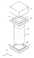
この条件(19)の前提となる構成は、正・負・正・開口絞り・正・負・正の屈折力配置であり、この条件(19)の範囲から外れる場合には、上記の屈折力配置では諸収差、特に軸外収差を補正することが困難になるため好ましくない。次に図面を参照して本発明の実施の形態にかかる投影光学系を投影露光装置に適用した例を示す。図1は本発明の実施の形態にかかる投影光学系を逐次露光型の投影露光装置に適用した例を示す斜視図であり、図2は本発明の実施の形態にかかる投影光学系を走査型露光装置に適用した例を示す斜視図である。
【0054】
これら図1および図2の投影露光装置は、ともに集積回路素子や液晶パネルなどのデバイスの回路パターンを形成する際の露光工程に用いられる。
まず、図1の例では、投影光学系PLの物体面には、所定の回路パターンが描かれた投影原板としてのマスクM(第1物体)が配置されており、投影光学系PLの像面には基板としてのプレートP(第2物体)が配置されている。ここで、マスクMはマスクステージに保持されており、図中XY方向に可動なプレートPはプレートステージPSに保持されている。また、マスクMの上方(Z方向側)には、紫外域の露光光によってマスクMの照明領域IAを均一に照明するための照明光学装置ILが配置されている。この実施の形態において、照明光学装置ILは、g線(435.8nm)からh線(404.7nm)までの紫外域の光を供給するものである。
【0055】
以上の構成により、照明光学装置ILから供給される紫外域の露光光は、マスクM上の照明領域IAを均一に照明し、このマスクMからの露光光は、投影光学系PLの開口絞りASの位置に光源像を形成する。すなわち、マスクMは照明光学装置ILによってケーラー照明される。そして、プレートP上の露光領域EAには、マスクMの照明領域IA内の像が形成され、これにより、プレートPにはマスクMの回路パターンが転写される。
【0056】
次に、図2の例では、マスクMを保持するマスクステージMSと、プレートPを保持するプレートステージPSとが、露光中において互いに逆方向へ走査する点が図1の例とは異なっている。これにより、プレートPには、マスクMの像が走査露光される。
以上の図1および図2の実施の形態では、投影光学系PLは、第1物体側(マスクM)側および第2物体側(プレートP側)において、実質的にテレセントリックとなっており、拡大倍率を有するものである。
【0057】
【実施例】
次に、図3乃至図6を参照して、本発明にかかる投影光学系の数値実施例について説明する。ここで、図3および図4は、第1および第2実施例の投影光学系のレンズ構成図であり、図5および図6は、第1および第2実施例の投影光学系の諸収差図である。
【0058】
[第1実施例]
図3において、第1実施例の投影光学系は、第1物体(マスクM)側から順に、正屈折力の第1レンズ群G1と、負屈折力の第2レンズ群G2と、正屈折力の第3レンズ群G3と、開口絞りASと、正屈折力の第4レンズ群G4と、負屈折力の第5レンズ群G5と、正屈折力の第6レンズ群G6とから構成される。
【0059】
ここで、第1レンズ群G1は、第1物体としてのマスクM側から順に、負屈折力の負サブレンズ群G1Nと、正屈折力の正サブレンズ群G1Pとから構成されており、負サブレンズ群G1Nは、第1物体側から順に、第2物体(プレートP)側に凹面を向けた平凹形状の負レンズ成分(第2物体側に凹面を向けた負レンズ成分)L11と、第1物体側に凹面を向けた平凹形状の負レンズ成分L12とを有し、正サブレンズ群G1Pは、第1物体側から順に、第2物体側に曲率の強い面を向けた両凸形状の2枚の正レンズ成分L13,L14と、第1物体側に凸面を向けた平凸形状の正レンズ成分L15とを有する。
【0060】
ここで、負サブレンズ群G1Nを構成する負レンズ成分L11,L12は、ともに条件(16)を満足する第2の硝材で構成されており、正サブレンズ群G1Pを構成する正レンズ成分L13〜L15は、条件(17)を満足する第3の硝材から構成されている。
第2レンズ群G2は、第1物体側から順に、第2物体側に凹面を向けた形状の正メニスカスレンズ成分L21および第2物体側に凹面を向けた形状の負メニスカスレンズ成分L22からなる接合レンズ成分と、両凹形状の負レンズ成分L23と、両凹形状の負レンズ成分L24および両凸形状の正レンズ成分L25からなり全体として第1物体側に凹面を向けたメニスカス形状の接合レンズ成分とを有する。
【0061】
ここで、負メニスカスレンズ成分L22と両凹形状の負レンズ成分L24とが第2レンズ群中の互いに向かい合った凹面の組を形成している。そして、全体として第1物体側に凹面を向けたメニスカス形状のサブレンズ群を構成している接合レンズ成分L24,L25においては、負レンズ成分L24が第3の硝材で構成されており、正レンズ成分L25が第2の硝材で構成されている。また、第2レンズ群中の負レンズ成分L24以外の負レンズ成分L22,L23は、第2の硝材で構成されている。
【0062】
第3レンズ群G3は、第1物体側から順に、第2物体側に曲率の強い面を向けた両凸形状の正レンズ成分L31と、第1物体側に曲率の強い面を向けた両凸形状の2枚の正レンズ成分L32,L33と、第2物体側に曲率の強い面を向けた両凹形状の負レンズ成分(第2物体側に凹面を向けたレンズ成分)L34とを有する。第3レンズ群G3においては、正レンズ成分L31〜L33が条件(15)を満たす第1の硝材で構成されており、最も第2物体側に配置されて第2物体側に凹面を向けた負レンズ成分L34が第2の硝材で構成されている。
【0063】
第4レンズ群は、第1物体側から順に、第1物体側に凹面を向けたメニスカス形状の負レンズ成分(第1物体側に凹面を向けたレンズ成分)L41と、第1物体側に凹面を向けた形状の正メニスカスレンズ成分L42と、第2物体側に曲率の強い面を向けた両凸形状の正レンズ成分L43と、両凸形状の正レンズ成分L44と、第1物体側に曲率の強い面を向けた両凸形状の正レンズ成分L45とを有する。第4レンズ群G4においては、最も第1物体側に配置されて第1物体側に凹面を向けた負レンズ成分L41が第2の硝材で構成されており、正レンズ成分L43〜L45が第1の硝材で構成されている。
【0064】
第5レンズ成分は、第1物体側から順に、両凸形状の正レンズ成分L51および両凹形状の負レンズ成分L52からなり全体として第2物体側に凹面を向けたメニスカス形状の接合レンズ成分と、両凹形状の負レンズ成分L53と、第1物体側に凹面を向けた平凹形状の負レンズ成分L54および第2物体側に凸面を向けた平凸形状の正レンズ成分L55からなる接合レンズ成分と、第1物体側に凹面を向けた平凹形状の負レンズ成分L56と、第2物体側に凸面を向けた平凸形状の正レンズ成分L57とを有する。
【0065】
ここで、両凹形状の負レンズ成分L52と平凹形状の負レンズ成分L56とが第5レンズ群中の互いに向かい合った凹面の組を形成している。そして、全体として第2物体側に凹面を向けたメニスカス形状のサブレンズ群を構成している接合レンズ成分L51,L52においては、正レンズ成分L51が第2の硝材で構成されており、負レンズ成分L52が第3の硝材で構成されている。また、第5レンズ群中の負レンズ成分L52以外の負レンズ成分L53,L54,L56は、第2の硝材で構成されている。
【0066】
そして、第6レンズ群G6は、第1物体側から順に、正屈折力の正サブレンズ群G6Pと、負屈折力の負サブレンズ群G6Nとから構成されており、正サブレンズ群G6Pは、第1物体側から順に、第2物体側に曲率の強い面を向けた両凸形状の正レンズ成分L61と、第1物体側に曲率の強い面を向けた両凸形状の正レンズ成分L62と、第1物体側に凸面を向けた平凸形状の正レンズ成分L63とを有し、負サブレンズ群G6Nは、第1物体側に凹面を向けた平凹形状の負レンズ成分(第1物体側に凹面を向けた負レンズ成分)L64を有する。
【0067】
ここで、正サブレンズ群を構成する正レンズ成分L61〜L63は、第3の硝材で構成されており、負サブレンズ群を構成する負レンズ成分L64は、第2の硝材で構成されている。
[第2実施例]
図4において、第2実施例の投影光学系は、第1物体(マスクM)側から順に、正屈折力の第1レンズ群G1と、負屈折力の第2レンズ群G2と、正屈折力の第3レンズ群G3と、開口絞りASと、正屈折力の第4レンズ群G4と、負屈折力の第5レンズ群G5と、正屈折力の第6レンズ群G6とから構成される。
【0068】
ここで、第1レンズ群G1は、第1物体としてのマスクM側から順に、負屈折力の負サブレンズ群G1Nと、正屈折力の正サブレンズ群G1Pとから構成されており、負サブレンズ群G1Nは、第2物体としてのプレートP側に両凹形状の負レンズ成分(第2物体側に凹面を向けた負レンズ成分)L11を有し、正サブレンズ群G1Pは、第1物体側から順に、第2物体側に曲率の強い面を向けた2枚の正レンズ成分L12,L13と、第1物体側に曲率の強い面を向けた両凸形状の正レンズ成分L14とを有する。
【0069】
ここで、負サブレンズ群G1Nを構成する負レンズ成分L11は、条件(16)を満足する第2の硝材で構成されており、正サブレンズ群G1Pを構成する正レンズ成分L12〜L14は、条件(17)を満足する第3の硝材から構成されている。
第2レンズ群G2は、第1物体側から順に、第2物体側に凹面を向けた形状の正メニスカスレンズ成分L21および第2物体側に凹面を向けた形状の負メニスカスレンズ成分L22からなる接合レンズ成分と、両凹形状の負レンズ成分L23と、両凹形状の負レンズ成分L24および両凸形状の正レンズ成分L25からなり全体として第1物体側に凹面を向けたメニスカス形状の接合レンズ成分とを有する。
【0070】
ここで、負メニスカスレンズ成分L22と両凹形状の負レンズ成分L24とが第2レンズ群中の互いに向かい合った凹面の組を形成している。そして、全体として第1物体側に凹面を向けたメニスカス形状のサブレンズ群を構成している接合レンズ成分L24,L25においては、負レンズ成分L24が第3の硝材で構成されており、正レンズ成分L25が第2の硝材で構成されている。また、第2レンズ群中の負レンズ成分L24以外の負レンズ成分L22,L23は、第2の硝材で構成されている。
【0071】
第3レンズ群G3は、第1物体側から順に、両凸形状の3枚の正レンズ成分L31〜L33と、第2物体側に曲率の強い面を向けた両凹形状の負レンズ成分(第2物体側に凹面を向けたレンズ成分)L34とを有する。第3レンズ群G3においては、正レンズ成分L31〜L33が条件(15)を満たす第1の硝材で構成されており、最も第2物体側に配置されて第2物体側に凹面を向けた負レンズ成分L34が第2の硝材で構成されている。
【0072】
第4レンズ群は、第1物体側から順に、第1物体側に凹面を向けたメニスカス形状の負レンズ成分(第1物体側に凹面を向けたレンズ成分)L41と、第1物体側に凹面を向けた形状の正メニスカスレンズ成分L42と、第2物体側に曲率の強い面を向けた両凸形状の正レンズ成分L43と、両凸形状の正レンズ成分L44と、第1物体側に凸面を向けたメニスカス形状の正レンズ成分L45とを有する。第4レンズ群G4においては、最も第1物体側に配置されて第1物体側に凹面を向けた負レンズ成分L41が第2の硝材で構成されており、正レンズ成分L43〜L45が第1の硝材で構成されている。
【0073】
第5レンズ成分は、第1物体側から順に、両凸形状の正レンズ成分L51および両凹形状の負レンズ成分L52からなり全体として第2物体側に凹面を向けたメニスカス形状の接合レンズ成分と、両凹形状の負レンズ成分L53と、第1物体側に曲率の強い面を向けた両凹形状の負レンズ成分L54および第2物体側に曲率の強い面を向けた両凸形状の正レンズ成分L55からなる接合レンズ成分とを有する。
【0074】
ここで、両凹形状の負レンズ成分L52と両凹形状の負レンズ成分L54とが第5レンズ群中の互いに向かい合った凹面の組を形成している。そして、全体として第2物体側に凹面を向けたメニスカス形状のサブレンズ群を構成している接合レンズ成分L51,L52においては、正レンズ成分L51が第2の硝材で構成されており、負レンズ成分L52が第3の硝材で構成されている。また、第5レンズ群中の負レンズ成分L52以外の負レンズ成分L53,L54は、第2の硝材で構成されている。
【0075】
そして、第6レンズ群G6は、第1物体側から順に、正屈折力の正サブレンズ群G6Pと、負屈折力の負サブレンズ群G6Nとから構成されており、正サブレンズ群G6Pは、第1物体側から順に、第2物体側に曲率の強い面を向けた両凸形状の正レンズ成分L61と、第1物体側に曲率の強い面を向けた両凸形状の正レンズ成分L62とを有し、負サブレンズ群G6Nは、第1物体側に凹面を向けたメニスカス形状の負レンズ成分(第1物体側に凹面を向けた負レンズ成分)L63を有する。
【0076】
ここで、正サブレンズ群を構成する正レンズ成分L61,L62は、第3の硝材で構成されており、負サブレンズ群を構成する負レンズ成分L63は、第2の硝材で構成されている。
さて、以下に示す表1および表2に数値実施例の諸元の値並びに条件対応数値を掲げる。
【0077】
但し、左端の数字は第1物体側(マスクM側)からの順序を表し、rはレンズ面の曲率半径、dはレンズ面間隔、n(G)は露光波長λが435.8nmにおける屈折率、n(H)は露光波長λが404.7nmにおける屈折率、n(400)は露光波長λが400nmにおける屈折率、n(440)は露光波長λが440nmにおける屈折率、d0は第1物体(マスクM)から第1レンズ群G1の最も第1物体側(マスクM側)のレンズ面(第1レンズ面)までの距離、WDは第6レンズ群G6の最も第2物体側(プレートP側)のレンズ面から第2物体面(プレートP面)までの距離、βは投影光学系の投影倍率、NAは投影光学系の第2物体側での開口数、φEXは第2物体面(プレートP面)における露光領域の半径、f1は第1レンズ群G1の焦点距離、f2は第2レンズ群G2の焦点距離、f3は第3レンズ群G3の焦点距離、f4は第4レンズ群G4の焦点距離、f5は第5レンズ群G5の焦点距離、f6は第6レンズ群G6の焦点距離、r2Rfは第2レンズ群G2中の一対の負レンズ成分のうち第1物体側に向けられた凹面の曲率半径、r2Frは第2レンズ群G2中の一対の負レンズ成分のうち第2物体側に向けられた凹面の曲率半径、r3Ffは第3レンズ群G3中の最も開口絞り側に配置された負レンズ成分の第2物体側に向けられた凹面の曲率半径、r4Rrは第4レンズ群G4中の最も開口絞り側に配置された負レンズ成分の第1物体側に向けられた凹面の曲率半径、r5Frは第5レンズ群G5中の一対の負レンズ成分のうち第2物体側に向けられた凹面の曲率半径、r5Rfは第5レンズ群G5中の一対の負レンズ成分のうち第1物体側に向けられた凹面の曲率半径、RG6は第6レンズ群G6を構成する正レンズ成分のレンズ面のうち第2物体側に凹面を向けたレンズ面の曲率半径、DG6は第6レンズ群G6を構成する正レンズ成分のレンズ面のうち第2物体側に凹面を向けたレンズ面と第2物体との距離を表している。
【0078】
【表1】

【表2】
【0080】
また、図5および図6はそれぞれ本発明による第1および第2実施例の投影光学系における諸収差図を示している。
ここで、各収差図において、NAは投影光学系の開口数、Yは像高、Gはg線(λ=435.8nm)、Hはh線(λ=404.7nm)を示しており、また、各非点収差図中において、点線は子午的像面(メリジオナル像面)、実線は球欠的像面(サジタル像面)を示している。
【0081】
各収差図の比較より、各実施例とも諸収差がバランス良く補正され、特に極めて広い露光領域の全てにおいて諸収差が良好に補正されており、かつg線およびh線についての色収差が良好になされていることが理解される。
これにより、各実施例の投影光学系を図1または図2に示す投影露光装置に適用した場合には、g線からh線までの広い波長域ので露光光を用いて露光を実現でき、露光時間の短縮化を達成することができる。
【0082】
また、各実施例の投影光学系では、極めて広い露光領域において良好な像を形成できるため、これら各実施例の投影光学系を用いて露光を行えば、良好なパターン像を広い範囲にわたって短時間で得ることができ、集積回路素子や液晶パネルなどのデバイス製造時のスループットを向上させることができる。
さて、上述の第1および第2実施例では、投影光学系がβ=1.25の拡大倍率を持つものとして説明したが、本発明は拡大倍率を有するものには限定されない。これら第1および第2実施例による投影光学系では、投影光学系における第1物体側(マスクM側)と第2物体側(プレートP側)とを逆転させた状態で使用して縮小倍率を得ることもできる。
【0083】
このとき、各実施例の投影光学系を逆転したものの条件対応数値は以下の表3の通りである。なお、この状態におけるレンズ構成図は、図3および図4における左右が反転するだけであるので図示省略し、諸収差図は、図5および図6の収差図のスケールを0.8倍したものと実質的に同一であるため図示省略する。このとき、図3および図4に示す第1レンズ群G1は第6レンズ群、第2レンズ群G2は第5レンズ群、第3レンズ群G3は第4レンズ群、第4レンズ群G4は第3レンズ群、第5レンズ群G5は第2レンズ群、そして第6レンズ群G6は第1レンズ群となる。
【0084】
【表3】
[第1実施例の投影光学系を逆転させたものの条件対応数値]
(1)|f1/f2|=2.15
(2)|f6/f5|=1.17
(3)f3/f4=0.42
(4)|β|=0.8
(5)|f1/f2|=2.15
(6)|f6/f5|=1.17
(7)f3/f4=0.42
(12)(r2Rf+r2Fr)/(r2Rf−r2Fr)=0.08
(13)(r4Ff+r3Rr)/(r4Ff−r3Rr)=-0.01
(14)(r5Rf+r5Fr)/(r5Rf−r5Fr)=-0.22
(19)|β|=0.8
[第2実施例の投影光学系を逆転させたものの条件対応数値]
(1)|f1/f2|=2.03
(2)|f6/f5|=1.06
(3)f3/f4=0.33
(4)|β|=0.8
(5)|f1/f2|=2.03
(6)|f6/f5|=1.06
(7)f3/f4=0.33
(12)(r2Rf+r2Fr)/(r2Rf−r2Fr)=0.16
(13)(r4Ff+r3Rr)/(r4Ff−r3Rr)=0.002
(14)(r5Rf+r5Fr)/(r5Rf−r5Fr)=-0.33
(19)|β|=0.8
なお、以上の各実施例では、光源としてg線からh線までの光を供給するものを用いた例を示したがこれに限ることなく、193nm,248.8nm の光を供給するエキシマレーザ等の極紫外光源や、i線(365nm)の光を供給する水銀アークランプ、さらにはそれ以外の紫外領域の光を供給する光源を用いたものにも応用し得ることは言うまでもない。
【0085】
また、各実施例では、投影光学系に複数の接合レンズ成分が含まれているが、レンズ成分を接合する代わりに、光学密着(オプチカル・コンタクト)で接合レンズ成分を構成しても良い。また、接合レンズ成分を構成する複数のレンズ成分を微少な間隔を開けて配置して、接合レンズ成分と等価に構成しても良い。
【0086】
【発明の効果】
以上の通り、本発明によれば、両側テレセントリックでありながら、広い露光領域にわたって諸収差を極めて良好に補正し得る高性能な投影光学系が実現できる。また、本発明の好ましい態様によれば、極めて広い露光領域において、広いスペクトル幅について良好に色収差補正がなされた投影光学系実現できる。
【図面の簡単な説明】
【図1】本発明にかかる投影光学系を一括露光型の投影露光装置に適用した例を概略的に示す斜視図である。
【図2】本発明にかかる投影光学系を走査露光型の投影露光装置に適用した例を概略的に示す斜視図である。
【図3】第1実施例の投影光学系のレンズ構成図である。
【図4】第2実施例の投影光学系のレンズ構成図である。
【図5】第1実施例の投影光学系の諸収差図である。
【図6】第2実施例の投影光学系の諸収差図である。
【符号の説明】
G1:第1レンズ群、
G2:第2レンズ群、
G3:第3レンズ群、
G4:第4レンズ群、
G5:第5レンズ群、
G6:第6レンズ群、
AS:開口絞り、[0001]
BACKGROUND OF THE INVENTION
The present invention relates to a projection optical system for projecting a pattern of a first object onto a substrate or the like as a second object, and particularly to a semiconductor or liquid crystal formed on a reticle (mask) as a first object. The present invention relates to a projection optical system suitable for projecting and exposing a pattern for use on a substrate (wafer, plate, etc.) as a second object.
[0002]
[Prior art]
As the pattern of an integrated circuit is further miniaturized, the performance required for a projection optical system used for printing a wafer is becoming stricter. Under such circumstances, to improve the resolution of the projection optical system, it is conceivable to shorten the exposure wavelength λ or increase the numerical aperture (NA) of the projection optical system.
[0003]
In such a projection exposure apparatus, exposure is performed using a light source that supplies exposure light from g-line (436 nm) to i-line (365 nm).
In the projection optical system, it is required to reduce image distortion along with improvement in resolution. Here, the image distortion is not only due to distortion (distortion aberration) caused by the projection optical system, but also due to warpage of the wafer baked on the image side of the projection optical system, circuit pattern on the object side of the projection optical system, etc. Is due to the warping of the reticle on which is drawn.
[0004]
In recent years, the transfer pattern has been further miniaturized, and the demand for reducing image distortion has become more severe.
Therefore, in order to reduce the influence on the image distortion due to the warpage of the wafer, a so-called image side telecentric optical system in which the exit pupil position on the image side of the projection optical system is located far has been used.
[0005]
On the other hand, to reduce image distortion due to reticle warpage, it is conceivable to use a so-called object-side telecentric optical system in which the entrance pupil position of the projection optical system is located far from the object plane. Proposals have been made to position the entrance pupil position relatively far from the object plane.
[0006]
[Problems to be solved by the invention]
In recent years, in a projection optical system, a wide exposure area has been required as well as an improvement in resolution.
Accordingly, an object of the present invention is to provide a high-performance projection optical system that is capable of correcting aberrations very well over a wide exposure area while being both-side telecentric.
[0007]
In addition, a projection exposure apparatus that uses short-wavelength exposure light is less susceptible to fluorescent radiation and solarization due to ultraviolet absorption, and requires the use of a glass material with high transmittance in the ultraviolet region. Moreover, since these glass materials have a low refractive index, it is difficult to correct aberrations.
In order to solve this problem, in the conventional exposure apparatus, the light from the light source is passed through the wavelength selection filter and limited to a narrow spectral width such that chromatic aberration can be substantially ignored. The other aberrations are corrected satisfactorily.
[0008]
However, the narrower the spectral width of the exposure light, the greater the energy loss, and it has been difficult to shorten the exposure time.
Therefore, another object is to provide a projection optical system in which a wide spectrum width is achromatic in a relatively wide exposure region.
[0009]
[Means for Solving the Problems]
To achieve the above object, a projection optical system according to an aspect of the present invention projects an image of a first object onto a second object,
In order from the first object side,
A first lens group having a positive refractive power;
A second lens group having a pair of negative lens components having negative refractive power and forming a pair of concave surfaces facing each other;
A third lens group having a positive refractive power and having a lens component disposed closest to the second object side and having a concave surface facing the second object side;
An aperture stop,
A fourth lens group having a positive refractive power and having a lens component disposed closest to the first object side and having a concave surface facing the first object side;
A fifth lens group having a pair of negative lens components having negative refractive power and forming a pair of concave surfaces facing each other;
And a sixth lens group having a positive refractive power.
[0010]
According to the preferable aspect of this invention, it is comprised so that the following conditions may be satisfied.
(1) 0.5 <| f1 / f2 | <3.0
(2) 0.5 <| f6 / f5 | <3.0
(3) 0.25 <f3 / f4 <4.0
However,
f1: the focal length of the first lens group,
f2: focal length of the second lens group,
f3: focal length of the third lens group,
f4: focal length of the fourth lens group,
f5: focal length of the fifth lens group,
f6: focal length of the sixth lens group,
It is.
[0011]
Moreover, according to another preferable aspect of this invention, it is comprised so that the following conditions may be satisfied.
(4) 0.5 ≦ | β | ≦ 1.1
(5) 1.0 <| f1 / f2 | <3.0
(6) 0.5 <| f6 / f5 | <2.0
(7) 0.25 <f3 / f4 <2.0
However,
β: lateral magnification of the projection optical system,
f1: the focal length of the first lens group,
f2: focal length of the second lens group,
f3: focal length of the third lens group,
f4: focal length of the fourth lens group,
f5: focal length of the fifth lens group,
f6: focal length of the sixth lens group,
It is.
[0012]
According to still another preferred embodiment of the present invention, the following conditions are satisfied.
(8) 1.1 <| β | ≦ 2.0
(9) 0.5 <| f1 / f2 | <2.0
(10) 1.0 <| f6 / f5 | <3.0
(11) 1.0 <f3 / f4 <4.0
However,
β: lateral magnification of the projection optical system,
f1: the focal length of the first lens group,
f2: focal length of the second lens group,
f3: focal length of the third lens group,
f4: focal length of the fourth lens group,
f5: focal length of the fifth lens group,
f6: focal length of the sixth lens group,
It is.
[0013]
Moreover, according to the preferable aspect of this invention, it is comprised so that the following conditions may be satisfied.
(12) (r2Rf + r2Fr) / (r2Rf-r2Fr)> 0.0
(13) -0.1 <(r4Ff + r3Rr) / (r4Ff-r3Rr) <0.1
(14) (r5Rf + r5Fr) / (r5Rf-r5Fr) <0.0
However,
r2Rf: radius of curvature of the concave surface facing the first object among the pair of negative lens components in the second lens group,
r2Fr: radius of curvature of the concave surface facing the second object side of the pair of negative lens components in the second lens group,
r3Ff: radius of curvature of the concave surface facing the second object side of the negative lens component arranged closest to the aperture stop in the third lens group,
r4Rr: radius of curvature of the concave surface facing the first object side of the negative lens component arranged closest to the aperture stop in the fourth lens group,
r5Fr: the radius of curvature of the concave surface facing the second object side of the pair of negative lens components in the fifth lens group,
r5Rf: radius of curvature of the concave surface facing the first object side of the pair of negative lens components in the fifth lens group,
It is.
[0014]
In order to achieve another object of the present invention as described above, at least two positive lens components of the positive lens components in the third lens group are formed of the first glass material, and the fourth lens group. Of the positive lens components in the middle, at least two positive lens components are preferably made of the first glass material, and preferably satisfy the following conditions.
(15) νt> 120
However,
νt: dispersion value of the first glass material,
And this variance value is
When the refractive index for the wavelength λ is n (λ),
v = {n (436) -1} / {n (400) -n (440)}
Defined by
[0015]
DETAILED DESCRIPTION OF THE INVENTION
The projection optical system according to one aspect of the present invention having the above-described configuration employs positive, negative, positive, aperture stop, positive, negative, and positive refractive power arrangements, and has as much symmetry as possible with respect to the aperture stop. Therefore, asymmetrical aberrations, particularly coma and distortion can be corrected very well.
[0016]
Next, the function of each lens group in such a projection optical system will be described.
First, the first lens group having a positive refractive power mainly contributes to correction of distortion while maintaining telecentricity on the first object side. The sixth lens group having a positive refractive power also contributes mainly to correction of distortion while maintaining the telecentricity on the second object side. Specifically, these first and sixth lens groups generate positive distortion and correct negative distortion generated from the second to fifth lens groups in a well-balanced manner.
[0017]
The second lens group and the fifth lens group having negative refractive power mainly have a function of correcting the Petzval sum of the entire system, and aim to flatten the image plane over a wide exposure area. The third lens group having a positive refractive power mainly contributes to correction of spherical aberration and contributes to correction of lower coma. Here, the lens component arranged closest to the aperture stop in the third lens group and having the concave surface facing the aperture stop side generates a positive Petzval sum by this concave surface, and the positive lens component in the third lens group And a function of correcting negative Petzval sum generated from the positive lens component in the fourth lens group and correcting negative spherical aberration generated from the fourth lens group having positive refractive power.
[0018]
The fourth lens group having a positive refractive power mainly contributes to correction of spherical aberration and contributes to correction of upper coma. Here, the lens component arranged closest to the aperture stop in the fourth lens group and having the concave surface facing the aperture stop side generates a positive Petzval sum by this concave surface, and the positive lens component in the third lens group And a function of correcting negative Petzval sum generated from the positive lens component in the fourth lens group and correcting negative spherical aberration generated from the fourth lens group having positive refractive power.
[0019]
In the projection optical system as described above, it is preferable that the following conditions (1) to (3) are satisfied.
(1) 0.5 <| f1 / f2 | <3.0
(2) 0.5 <| f6 / f5 | <3.0
(3) 0.25 <f3 / f4 <4.0
However,
f1: the focal length of the first lens group,
f2: focal length of the second lens group,
f3: focal length of the third lens group,
f4: focal length of the fourth lens group,
f5: focal length of the fifth lens group,
f6: focal length of the sixth lens group,
It is.
[0020]
The condition (1) defines an optimum ratio between the focal length f1 of the first lens unit having positive refractive power and the focal length of the second lens unit having negative refractive power. This condition (1) is mainly for correcting distortion aberration in a well-balanced manner and for correcting Petzval sum well.
Exceeding the lower limit of the condition (1) is not preferable because positive distortion is greatly generated, and positive Petzval sum is generated, which makes it difficult to correct curvature of field. Here, in order to correct the positive distortion aberration and the positive Petzval sum more satisfactorily, it is preferable to set the lower limit of the condition (1) to 0.8.
[0021]
On the other hand, when the upper limit of the condition (1) is exceeded, negative distortion is greatly generated, and negative Petzval sum is generated, so that it is difficult to correct field curvature, and further, the total length of the projection optical system Is not preferable because it becomes longer. Here, in order to further correct the negative distortion aberration and the negative Petzval sum, it is preferable to set the upper limit of the condition (1) to 1.4.
[0022]
In the above condition (2), in order to mainly correct the distortion aberration in a well-balanced manner and to correct the Petzval sum well, the focal length f6 of the sixth lens unit with positive refractive power and the fifth lens unit with negative refractive power are used. It defines the optimal ratio with the focal length.
Exceeding the lower limit of the condition (2) is not preferable because positive distortion is greatly generated and a positive Petzval sum is generated, which makes it difficult to correct curvature of field. Here, in order to correct the positive distortion aberration and the positive Petzval sum more satisfactorily, it is preferable to set the lower limit of the condition (2) to 1.8.
[0023]
On the contrary, when the upper limit of the condition (2) is exceeded, a large amount of negative distortion is generated, and a negative Petzval sum is generated, which makes it difficult to correct the field curvature. This is not preferable because the total length becomes long. Here, in order to further correct the negative distortion aberration and the negative Petzval sum, it is preferable to set the upper limit of the condition (2) to 2.4.
[0024]
Condition (3) defines an optimum ratio between the focal length f3 of the third lens unit having positive refractive power and the focal length f4 of the fourth lens unit having positive refractive power, and mainly includes spherical aberration and coma aberration. It is for correcting with a good balance.
Exceeding the lower limit of condition (3) is not preferable because the spherical aberration is unbalanced and positive spherical aberration occurs and coma also deteriorates. Here, in order to correct positive spherical aberration and coma aberration more satisfactorily, it is preferable to set the lower limit of the condition (3) to 2.0.
[0025]
Exceeding the upper limit of condition (3) is not preferable because the spherical aberration is unbalanced and negative spherical aberration is generated, and further coma is deteriorated. Here, in order to satisfactorily correct negative spherical aberration and coma, it is preferable to set the upper limit of the condition (3) to 3.5.
In the projection optical system as described above, when the lateral magnification of the projection optical system satisfies the following condition (4), it is preferable that the conditions (5) to (7) are satisfied.
(4) 0.5 ≦ | β | ≦ 1.1
(5) 1.0 <| f1 / f2 | <3.0
(6) 0.5 <| f6 / f5 | <2.0
(7) 0.25 <f3 / f4 <2.0
The above condition (5) is that when the lateral magnification of the projection optical system is within the range of the condition (4), the positive refracting power is mainly used to correct the distortion aberration in a well-balanced manner and the Petzval sum. This defines an optimum ratio between the focal length f1 of the first lens group and the focal length of the second lens group having negative refractive power.
[0026]
Exceeding the lower limit of the condition (5) is not preferable because a large positive distortion is generated and a positive Petzval sum is generated, which makes it difficult to correct curvature of field. On the other hand, when the upper limit of the condition (5) is exceeded, negative distortion is greatly generated, and negative Petzval sum is generated, which makes it difficult to correct the curvature of field, and further, the total length of the projection optical system. Is not preferable because it becomes longer.
[0027]
In the condition (6), when the lateral magnification of the projection optical system is within the range of the condition (4), the positive refractive power is mainly used to correct the distortion aberration in a well-balanced manner and the Petzval sum. The optimum ratio between the focal length f6 of the sixth lens group and the focal length of the fifth lens group having negative refractive power is defined.
Exceeding the lower limit of the condition (6) is not preferable because a large positive distortion is generated and a positive Petzval sum is generated, which makes it difficult to correct curvature of field. On the contrary, when the upper limit of the condition (6) is exceeded, negative distortion is greatly generated, and negative Petzval sum is generated, which makes it difficult to correct field curvature. This is not preferable because the total length becomes long.
[0028]
Condition (7) is a third lens group having a positive refractive power in order to mainly correct spherical aberration and coma in a balanced manner when the lateral magnification of the projection optical system is within the range of condition (4). The optimum ratio between the focal length f3 and the focal length f4 of the fourth lens unit having a positive refractive power is defined.
Exceeding the lower limit of condition (7) is not preferable because the spherical aberration is out of balance and positive spherical aberration occurs, and coma also deteriorates. Exceeding the upper limit of condition (7) is not preferable because the spherical aberration is unbalanced and negative spherical aberration is generated, and further coma is deteriorated.
[0029]
In the projection optical system as described above, when the lateral magnification of the projection optical system satisfies the following condition (8), it is preferable that the conditions (9) to (11) are satisfied. (8) 1.1 <| β | ≦ 2.0
(9) 0.5 <| f1 / f2 | <2.0
(10) 1.0 <| f6 / f5 | <3.0
(11) 1.0 <f3 / f4 <4.0
The above condition (9) is that the positive refracting power is mainly used to correct the distortion aberration in a well-balanced manner and to correct the Petzval sum when the lateral magnification of the projection optical system is within the range of the condition (8). This defines an optimum ratio between the focal length f1 of the first lens group and the focal length of the second lens group having negative refractive power.
[0030]
Exceeding the lower limit of the condition (9) is not preferable because positive distortion is greatly generated, and positive Petzval sum is generated, which makes it difficult to correct curvature of field. On the other hand, when the upper limit of the condition (9) is exceeded, negative distortion is greatly generated, and negative Petzval sum is generated, so that it is difficult to correct curvature of field, and further, the total length of the projection optical system. Is not preferable because it becomes longer.
[0031]
In the above condition (10), when the lateral magnification of the projection optical system is within the range of the condition (8), in order to correct mainly the distortion aberration in a well-balanced manner and the Petzval sum, the positive refractive power The optimum ratio between the focal length f6 of the sixth lens group and the focal length of the fifth lens group having negative refractive power is defined.
Exceeding the lower limit of the condition (10) is not preferable because a large positive distortion is generated and a positive Petzval sum is generated, which makes it difficult to correct curvature of field. On the contrary, when the upper limit of the condition (10) is exceeded, a large amount of negative distortion is generated, and a negative Petzval sum is generated, which makes it difficult to correct the curvature of field. This is not preferable because the total length becomes long.
[0032]
Condition (11) is a third lens group having a positive refractive power in order to correct mainly spherical aberration and coma with a good balance when the lateral magnification of the projection optical system is within the range of condition (8). The optimum ratio between the focal length f3 and the focal length f4 of the fourth lens unit having a positive refractive power is defined.
Exceeding the lower limit of condition (11) is not preferable because the spherical aberration is unbalanced and positive spherical aberration occurs, and coma also deteriorates. Exceeding the upper limit of condition (11) is not preferable because the spherical aberration is unbalanced and negative spherical aberration occurs, and coma also deteriorates.
[0033]
In the projection optical system according to one aspect of the present invention, it is preferable that the following conditions (12) to (14) are satisfied.
(12) (r2Rf + r2Fr) / (r2Rf-r2Fr)> 0.0
(13) -0.1 <(r4Ff + r3Rr) / (r4Ff-r3Rr) <0.1
(14) (r5Rf + r5Fr) / (r5Rf-r5Fr) <0.0
However,
r2Rf: radius of curvature of the concave surface facing the first object among the pair of negative lens components in the second lens group,
r2Fr: radius of curvature of the concave surface facing the second object side of the pair of negative lens components in the second lens group,
r3Ff: radius of curvature of the concave surface facing the second object side of the negative lens component arranged closest to the aperture stop in the third lens group,
r4Rr: radius of curvature of the concave surface facing the first object side of the negative lens component arranged closest to the aperture stop in the fourth lens group,
r5Fr: the radius of curvature of the concave surface facing the second object side of the pair of negative lens components in the fifth lens group,
r5Rf: radius of curvature of the concave surface facing the first object side of the pair of negative lens components in the fifth lens group,
It is.
The condition (12) defines the optimum shape of the concave surfaces facing each other in the second lens group. Here, considering the off-axis chief ray, the off-axis chief ray is refracted by the positive first lens group, enters the negative second lens group at a predetermined angle, and faces each other in the second lens group. The concave surface is refracted so as to be lifted by a concave surface located on the first object side (a concave surface directed toward the second object side). When the range of the condition (12) is not satisfied, the curvature of the concave surface directed toward the second object side in the second lens group becomes too loose, and the off-axis principal ray refracted by the first lens group is sufficiently absorbed. Can not be lifted. In this case, if the refractive state of the off-axis principal ray in the third lens group is kept constant, it is necessary to make the first lens group sufficiently thick, which is not preferable because the entire length of the projection optical system becomes long. . Further, if the condition (12) is not satisfied, the Petzval sum cannot be corrected sufficiently, which is not preferable.
[0034]
Condition (13) defines the preferred shape of the gas lens formed by the opposing concave surfaces adjacent to the aperture stop. Here, if the condition is outside the range of the condition (13), the symmetry of the shape of the gas lens is lost, and coma aberration is generated. In addition, correction of spherical aberration and Petzval sum is difficult, which is not preferable.
Condition (14) defines the optimum shape of the concave surfaces facing each other in the fifth lens group. Here, considering the off-axis chief ray, this off-axis chief ray is incident on the fifth lens group at a predetermined angle from the fourth lens group, and the second object side of the concave surfaces facing each other in the fifth lens group. After being refracted so as to be raised at the concave surface located at (the concave surface directed toward the first object), it is refracted by the sixth lens group. If the range of the condition (14) is not satisfied, the curvature of the concave surface directed toward the first object in the fifth lens group becomes too loose, and the off-axis principal ray cannot be sufficiently raised. In this case, it is necessary to make the thickness of the sixth lens group sufficiently, and the total length of the projection optical system becomes long, which is not preferable. Further, if it falls outside the range of the condition (14), the Petzval sum cannot be corrected sufficiently, which is not preferable.
[0035]
The lens component arranged closest to the aperture stop in the third lens group and having the concave surface facing the second object side is a negative lens component, and is arranged closest to the aperture stop in the fourth lens group. The lens component with the concave surface facing the object side is preferably a negative lens component.
The first lens group includes, in order from the first object side, a negative sub lens group having negative refractive power and a positive sub lens group having positive refractive power, and the sixth lens group is provided on the first object side. In order, a negative sub-lens group having a positive refractive power and a negative sub-lens group having a negative refractive power. The negative sub-lens group in the first lens group has a negative surface with a concave surface facing the second object side. It is preferable that the negative sub lens group in the sixth lens group has a negative lens component having a concave surface facing the first object side.
[0036]
In this way, when the first lens group closest to the first object side and the sixth lens group closest to the second object side are configured, deterioration of the resist image due to flare can be suppressed. This point will be described in detail below.
As performance required for the projection optical system, Seidel's five aberrations (spherical aberration, coma aberration, astigmatism, field curvature and distortion aberration) and chromatic aberration (axial chromatic aberration and lateral chromatic aberration) are well corrected. In addition, flare may not occur. The cause of this flare is that the exposure light is reflected by the lens surface of the projection optical system, and that the exposure light reflected by the surface of the substrate as the second object is reflected by the lens surface of the projection optical system. Etc. When the amount of flare increases, a variation in the line width of the resist image (resist pattern formed based on the image formed on the resist on the substrate by the projection optical system) occurs, so that a good resist image is obtained. For this purpose, it is desired not only to correct the imaging aberration well but also to suppress flare.
[0037]
In particular, in a projection optical system having a large exposure area as in the present invention, since the exposure light reflected on the surface of the substrate (second object) increases compared to a projection optical system having a small exposure area, flare due to this reflection tends to increase. Tend.
Further, when the projection magnification of the projection optical system becomes low, it becomes difficult to reduce the flare amount. The lower the magnification, the smaller the numerical aperture of the projection optical system and the lower the illuminance of the exposure amount that contributes to image formation. For this reason, even if a slight flare exists, the resist image tends to deteriorate.
[0038]
Such flare is likely to occur in the first and sixth lens groups as the field lens group. These first and sixth lens groups are configured to have a positive lens component. Of these positive lens components, the flare generated from the lens surface having the concave toward the first object side in the first lens group, and from the lens surface having the concave toward the second object side in the sixth lens group, On the object or the second object, it tends to gather near the optical axis of the projection optical system, and there is a risk of causing variations in the line width of the resist image within the exposure region.
[0039]
Therefore, in the sixth lens group, it is desirable to optimize the curvature of the lens surface with the concave toward the second object side in the positive lens component so that the flare does not converge near the optical axis. However, since the optimal curvature for reducing flare is not necessarily optimal in the imaging performance, this sixth lens group, in order from the first object side, a positive sub-lens group having positive refractive power, It is preferable to have a negative sub-lens group having a negative refractive power, and to control the refractive power of the positive sub-lens group to be optimal in imaging performance by this negative sub-lens group.
[0040]
With such a configuration, it is possible to satisfactorily correct the imaging performance, particularly distortion, field curvature, and telecentricity, without the flare condensing near the optical axis.
Similarly, if the first lens group includes, in order from the first object side, a negative sub-lens group having negative refracting power and a positive sub-lens group having positive refracting power, imaging performance is achieved. In particular, while maintaining good distortion, curvature of field, and telecentricity, the flare collects the curvature of the lens surface with the concave toward the first object side in the positive lens component in the first lens group near the optical axis. It is possible to optimize so as not to shine.
[0041]
In a preferred aspect of the present invention, at least two positive lens components of the positive lens components in the third lens group are formed of the first glass material, and among the positive lens components in the fourth lens group. These at least two positive lens components are preferably made of the first glass material.
Here, the first glass material is expressed under the following conditions when the dispersion value of the first glass material is νt.
(15) νt> 120
However, the dispersion value is n (λ) when the refractive index with respect to the wavelength λ is
v = {n (436) -1} / {n (400) -n (440)}
Defined by
[0042]
As described above, the third and fourth lens groups have a function of correcting spherical aberration, but as described above, at least two of the plurality of positive lens components in the third and fourth lens groups. By using the first glass material having a large dispersion value represented by the condition (15) as the positive lens component, the achromaticity on the axis of the entire projection optical system can be satisfactorily performed. In the above-described configuration, the lens component disposed closest to the second object side in the third lens group is configured by the second glass material, and the lens component disposed closest to the first object side in the fourth lens group is the first lens component. It is preferable that it is composed of two glass materials.
[0043]
Here, when the dispersion value of the second glass material is νc,
(16) νc <110
It is represented by
As described above, in the third and fourth lens groups, by using the second glass material represented by the condition (16) as the lens component that is arranged closest to the aperture stop and faces the concave surface toward the aperture stop, Good on-axis achromaticity can be achieved.
[0044]
In the embodiment of the present invention, the positive lens component disposed adjacent to at least one of the pair of negative lens components in the second lens group and the pair in the fifth lens group. And a positive lens component disposed adjacent to at least one of the negative lens components.
In this configuration, at least one negative lens component in the second lens group and a positive lens component adjacent thereto are meniscus as a whole, and are adjacent to at least one negative lens component in the fifth lens group. The positive lens component is preferably meniscus as a whole.
[0045]
Here, of the negative lens component and the positive lens component having a meniscus shape as a whole in the second lens group, the negative lens component is composed of the third glass material, and the positive lens component is composed of the second glass material, Of the negative lens component and the positive lens component having a meniscus shape as a whole in the fifth lens group, the negative lens component is preferably composed of a third glass material, and the positive lens component is preferably composed of a second glass material.
[0046]
However, the third glass material is expressed under the following conditions when the dispersion value of the third glass material is νf.
(17) νf <75
As described above, the third glass material represented by the condition (17) is used as the negative lens component constituting the meniscus-shaped sub-lens group as a whole in the second lens group, and the positive lens component according to the condition (16). The third glass material represented by the condition (17) is used for the negative lens component constituting the meniscus-shaped sub lens group as a whole in the fifth lens group, and the positive lens component is used. By using the second glass material represented by the condition (16), the spherical aberration of color is excessively generated from these sub lens groups. Accordingly, it is possible to cancel the spherical aberration of a color that tends to be under only by the third and fourth lens groups, and it is possible to achieve a spherical aberration of a good color as the entire projection optical system.
[0047]
In addition, at least one positive lens component in the positive sub-lens group in the first lens group is formed of a third glass material, and at least one negative lens in the negative sub-lens group in the first lens group. The component is composed of the second glass material, and at least one positive lens component of the positive sub-lens group in the sixth lens group is composed of the third glass material, and the negative sub-lens group in the sixth lens group It is preferable that at least one of the negative lens components is composed of the second glass material.
[0048]
With this configuration, in the first and sixth lens groups, the curvature of field of the color can be made under, thereby canceling the curvature of field of the color that tends to be over in the second to fifth lens groups. it can. Thereby, the curvature of field of the color of the entire projection optical system can be corrected satisfactorily.
Further, a negative lens component different from a negative lens component composed of the third glass material among negative lens components in the second lens group is composed of the second glass material, and the negative lens component in the fifth lens group Among these, it is preferable that the negative lens component different from the negative lens component configured by the third glass material is configured by the second glass material.
[0049]
Of the negative lens components in the second and fifth lens groups, the second glass material represented by the above condition (16) can suppress the secondary color dispersion on the axis, and further the color image plane. The curvature can be corrected well.
The negative meniscus lens component and the positive lens component as a whole in the second lens group described above are arranged with the concave surface facing the first object side, and the negative meniscus shape as a whole in the fifth lens group. The lens component and the positive lens component are preferably arranged with the concave surface facing the second object side.
[0050]
With the above configuration, since the arrangement of the glass material becomes almost symmetrical, there is an effect that the occurrence of chromatic aberration of magnification and chromatic coma aberration can be reduced.
The positive sub lens group in the sixth lens group preferably has a lens surface that satisfies the following condition (18).
(18) RG6 / DG6 <2
However,
RG6: the radius of curvature of the lens surface of the positive lens component constituting the positive sub-lens group in the sixth lens group with the convex surface facing the first object side,
DG6: Distance between this lens surface and the second object,
It is.
[0051]
The condition (18) is for preventing flare on the second object. When the condition (18) is not satisfied, flare light that is reflected by the lens surface having the concave toward the second object side in the positive lens component in the positive sub-lens group of the sixth lens group and travels toward the second object is This is not preferable because the light is condensed near the optical axis on the second object.
[0052]
The projection optical system in the present embodiment preferably satisfies the following condition (19).
(19) 0.5 ≦ | β | ≦ 2.0
However,
β: Projection magnification of the projection optical system,
It is.
[0053]
The preconditions of this condition (19) are positive / negative / positive / aperture stop / positive / negative / positive refractive power arrangement, and if it falls outside the range of this condition (19), the above refractive power The arrangement is not preferable because it is difficult to correct various aberrations, particularly off-axis aberrations. Next, an example in which the projection optical system according to the embodiment of the present invention is applied to a projection exposure apparatus will be described with reference to the drawings. FIG. 1 is a perspective view showing an example in which a projection optical system according to an embodiment of the present invention is applied to a sequential exposure type projection exposure apparatus, and FIG. 2 is a scanning type projection optical system according to an embodiment of the present invention. It is a perspective view which shows the example applied to the exposure apparatus.
[0054]
1 and 2 are both used in an exposure process when forming a circuit pattern of a device such as an integrated circuit element or a liquid crystal panel.
First, in the example of FIG. 1, a mask M (first object) as a projection original plate on which a predetermined circuit pattern is drawn is arranged on the object plane of the projection optical system PL, and the image plane of the projection optical system PL A plate P (second object) as a substrate is disposed in the plate. Here, the mask M is held on the mask stage, and the plate P movable in the XY directions in the figure is held on the plate stage PS. In addition, an illumination optical device IL for uniformly illuminating the illumination area IA of the mask M with ultraviolet exposure light is disposed above the mask M (Z direction side). In this embodiment, the illumination optical device IL supplies light in the ultraviolet region from g-line (435.8 nm) to h-line (404.7 nm).
[0055]
With the above configuration, the ultraviolet exposure light supplied from the illumination optical device IL uniformly illuminates the illumination area IA on the mask M, and the exposure light from the mask M is used as the aperture stop AS of the projection optical system PL. A light source image is formed at the position. That is, the mask M is Koehler illuminated by the illumination optical device IL. An image in the illumination area IA of the mask M is formed in the exposure area EA on the plate P, whereby the circuit pattern of the mask M is transferred to the plate P.
[0056]
Next, the example of FIG. 2 is different from the example of FIG. 1 in that the mask stage MS that holds the mask M and the plate stage PS that holds the plate P scan in opposite directions during exposure. . As a result, the image of the mask M is scanned and exposed on the plate P.
In the embodiment shown in FIGS. 1 and 2, the projection optical system PL is substantially telecentric on the first object side (mask M) side and the second object side (plate P side). It has a magnification.
[0057]
【Example】
Next, numerical examples of the projection optical system according to the present invention will be described with reference to FIGS. Here, FIGS. 3 and 4 are lens configuration diagrams of the projection optical systems of the first and second examples, and FIGS. 5 and 6 are various aberration diagrams of the projection optical systems of the first and second examples. It is.
[0058]
[First embodiment]
In FIG. 3, the projection optical system of the first example includes a first lens group G1 having a positive refractive power, a second lens group G2 having a negative refractive power, and a positive refractive power in order from the first object (mask M) side. The third lens group G3, the aperture stop AS, the fourth lens group G4 with positive refractive power, the fifth lens group G5 with negative refractive power, and the sixth lens group G6 with positive refractive power.
[0059]
Here, the first lens group G1 is composed of a negative sub lens group G1N having negative refractive power and a positive sub lens group G1P having positive refractive power in order from the mask M side as the first object. The lens group G1N includes, in order from the first object side, a plano-concave negative lens component having a concave surface facing the second object (plate P) side (a negative lens component having a concave surface facing the second object side) L11, A negative lens component L12 having a plano-concave shape with a concave surface facing one object side, and the positive sub-lens group G1P has a biconvex shape with a strongly curved surface facing the second object side in order from the first object side 2 positive lens components L13 and L14, and a plano-convex positive lens component L15 having a convex surface facing the first object side.
[0060]
Here, the negative lens components L11 and L12 constituting the negative sub lens group G1N are both made of the second glass material satisfying the condition (16), and the positive lens components L13 to L13 constituting the positive sub lens group G1P are arranged. L15 is made of a third glass material that satisfies the condition (17).
The second lens group G2 is composed of, in order from the first object side, a positive meniscus lens component L21 having a concave surface facing the second object side and a negative meniscus lens component L22 having a concave surface facing the second object side. A meniscus cemented lens component consisting of a lens component, a biconcave negative lens component L23, a biconcave negative lens component L24, and a biconvex positive lens component L25 with the concave surface facing the first object as a whole. And have.
[0061]
Here, the negative meniscus lens component L22 and the biconcave negative lens component L24 form a pair of concave surfaces facing each other in the second lens group. In the cemented lens components L24 and L25 constituting the meniscus sub lens group having the concave surface facing the first object as a whole, the negative lens component L24 is composed of a third glass material, and the positive lens Component L25 is made of the second glass material. Further, the negative lens components L22 and L23 other than the negative lens component L24 in the second lens group are made of the second glass material.
[0062]
The third lens group G3 includes, in order from the first object side, a biconvex positive lens component L31 having a strongly curved surface facing the second object side, and a biconvex surface having a strongly curved surface facing the first object side. It has two positive lens components L32 and L33 having a shape, and a biconcave negative lens component (a lens component having a concave surface facing the second object side) L34 having a strongly curved surface facing the second object side. In the third lens group G3, the positive lens components L31 to L33 are made of the first glass material that satisfies the condition (15), and the negative lens is disposed closest to the second object side and has a concave surface facing the second object side. The lens component L34 is made of the second glass material.
[0063]
The fourth lens group includes, in order from the first object side, a meniscus negative lens component (lens component having a concave surface facing the first object side) L41 having a concave surface facing the first object side, and a concave surface facing the first object side A positive meniscus lens component L42 having a shape facing the lens, a biconvex positive lens component L43 having a strongly curved surface facing the second object side, a positive lens component L44 having a biconvex shape, and a curvature facing the first object side. A positive lens component L45 having a biconvex shape with a strong surface facing the lens. In the fourth lens group G4, the negative lens component L41 that is disposed closest to the first object side and has the concave surface facing the first object side is formed of the second glass material, and the positive lens components L43 to L45 are the first one. Made of glass material.
[0064]
The fifth lens component includes, in order from the first object side, a biconvex positive lens component L51 and a biconcave negative lens component L52, and a meniscus cemented lens component having a concave surface facing the second object as a whole. A cemented lens comprising a biconcave negative lens component L53, a plano-concave negative lens component L54 having a concave surface facing the first object side, and a plano-convex positive lens component L55 having a convex surface facing the second object side And a plano-concave negative lens component L56 having a concave surface facing the first object side, and a plano-convex positive lens component L57 having a convex surface facing the second object side.
[0065]
Here, the biconcave negative lens component L52 and the planoconcave negative lens component L56 form a pair of concave surfaces facing each other in the fifth lens group. In the cemented lens components L51 and L52 constituting the meniscus-shaped sub-lens group having the concave surface facing the second object side as a whole, the positive lens component L51 is composed of the second glass material, and the negative lens The component L52 is composed of a third glass material. Further, the negative lens components L53, L54, and L56 other than the negative lens component L52 in the fifth lens group are made of the second glass material.
[0066]
The sixth lens group G6 includes, in order from the first object side, a positive sub lens group G6P having a positive refractive power and a negative sub lens group G6N having a negative refractive power. The positive sub lens group G6P includes: In order from the first object side, a biconvex positive lens component L61 with a strongly curved surface facing the second object side, and a biconvex positive lens component L62 with a strongly curved surface facing the first object side, The negative sub-lens group G6N includes a plano-convex negative lens component (first object) having a convex surface facing the first object side and a concave surface facing the first object side. Negative lens component) L64 having a concave surface on the side.
[0067]
Here, the positive lens components L61 to L63 constituting the positive sub-lens group are made of a third glass material, and the negative lens component L64 constituting the negative sub-lens group is made of a second glass material. .
[Second Embodiment]
In FIG. 4, the projection optical system of the second example includes a first lens group G1 having a positive refractive power, a second lens group G2 having a negative refractive power, and a positive refractive power in order from the first object (mask M) side. The third lens group G3, the aperture stop AS, the fourth lens group G4 with positive refractive power, the fifth lens group G5 with negative refractive power, and the sixth lens group G6 with positive refractive power.
[0068]
Here, the first lens group G1 is composed of a negative sub lens group G1N having negative refractive power and a positive sub lens group G1P having positive refractive power in order from the mask M side as the first object. The lens group G1N has a biconcave negative lens component (negative lens component with a concave surface facing the second object side) L11 on the plate P side as the second object, and the positive sub-lens group G1P has the first object In order from the side, there are two positive lens components L12 and L13 having a strongly curved surface facing the second object side, and a biconvex positive lens component L14 having a strongly curved surface facing the first object side. .
[0069]
Here, the negative lens component L11 constituting the negative sub lens group G1N is made of a second glass material that satisfies the condition (16), and the positive lens components L12 to L14 constituting the positive sub lens group G1P are: It is made of a third glass material that satisfies the condition (17).
The second lens group G2 is composed of, in order from the first object side, a positive meniscus lens component L21 having a concave surface facing the second object side and a negative meniscus lens component L22 having a concave surface facing the second object side. A meniscus cemented lens component consisting of a lens component, a biconcave negative lens component L23, a biconcave negative lens component L24, and a biconvex positive lens component L25 with the concave surface facing the first object as a whole. And have.
[0070]
Here, the negative meniscus lens component L22 and the biconcave negative lens component L24 form a pair of concave surfaces facing each other in the second lens group. In the cemented lens components L24 and L25 constituting the meniscus sub lens group having the concave surface facing the first object as a whole, the negative lens component L24 is composed of a third glass material, and the positive lens Component L25 is made of the second glass material. Further, the negative lens components L22 and L23 other than the negative lens component L24 in the second lens group are made of the second glass material.
[0071]
The third lens group G3 includes, in order from the first object side, three biconvex positive lens components L31 to L33 and a biconcave negative lens component (first lens) having a strongly curved surface facing the second object side. 2 lens component L34 having a concave surface facing the object side. In the third lens group G3, the positive lens components L31 to L33 are made of the first glass material that satisfies the condition (15), and the negative lens is disposed closest to the second object side and has a concave surface facing the second object side. The lens component L34 is made of the second glass material.
[0072]
The fourth lens group includes, in order from the first object side, a meniscus negative lens component (lens component having a concave surface facing the first object side) L41 having a concave surface facing the first object side, and a concave surface facing the first object side A positive meniscus lens component L42 having a shape facing the surface, a biconvex positive lens component L43 having a strong curvature surface facing the second object side, a biconvex positive lens component L44, and a convex surface facing the first object side And a meniscus-shaped positive lens component L45 facing the lens. In the fourth lens group G4, the negative lens component L41 that is disposed closest to the first object side and has the concave surface facing the first object side is formed of the second glass material, and the positive lens components L43 to L45 are the first one. Made of glass material.
[0073]
The fifth lens component includes, in order from the first object side, a biconvex positive lens component L51 and a biconcave negative lens component L52, and a meniscus cemented lens component having a concave surface facing the second object as a whole. , A biconcave negative lens component L53, a biconcave negative lens component L54 having a strong curvature surface facing the first object side, and a biconvex positive lens having a curvature surface facing the second object side And a cemented lens component composed of component L55.
[0074]
Here, the biconcave negative lens component L52 and the biconcave negative lens component L54 form a pair of concave surfaces facing each other in the fifth lens group. In the cemented lens components L51 and L52 constituting the meniscus-shaped sub-lens group having the concave surface facing the second object side as a whole, the positive lens component L51 is composed of the second glass material, and the negative lens The component L52 is composed of a third glass material. Further, the negative lens components L53 and L54 other than the negative lens component L52 in the fifth lens unit are made of the second glass material.
[0075]
The sixth lens group G6 includes, in order from the first object side, a positive sub lens group G6P having a positive refractive power and a negative sub lens group G6N having a negative refractive power. The positive sub lens group G6P includes: In order from the first object side, a biconvex positive lens component L61 with a strongly curved surface facing the second object side, and a biconvex positive lens component L62 with a strongly curved surface facing the first object side, The negative sub lens group G6N includes a meniscus negative lens component having a concave surface facing the first object side (negative lens component having a concave surface facing the first object side) L63.
[0076]
Here, the positive lens components L61 and L62 constituting the positive sub lens group are made of a third glass material, and the negative lens component L63 constituting the negative sub lens group is made of a second glass material. .
Tables 1 and 2 below show values of numerical values and numerical values corresponding to conditions in numerical examples.
[0077]
However, the leftmost number represents the order from the first object side (mask M side), r is the radius of curvature of the lens surface, d is the lens surface interval, n (G) is the refractive index at an exposure wavelength λ of 435.8 nm, n (H) is the refractive index when the exposure wavelength λ is 404.7 nm, n (400) is the refractive index when the exposure wavelength λ is 400 nm, n (440) is the refractive index when the exposure wavelength λ is 440 nm, and d 0 is the first object (mask). M) to the lens surface (first lens surface) closest to the first object side (mask M side) of the first lens group G1, WD is the second object side (plate P side) of the sixth lens group G6. Is the distance from the lens surface to the second object surface (plate P surface), β is the projection magnification of the projection optical system, NA is the numerical aperture on the second object side of the projection optical system, and φEX is the second object surface (plate P) Radius of the exposure area on the surface), f1 is the focal length of the first lens group G1, f2 is the focal length of the second lens group G2, and f3 is The focal length of the third lens group G3, f4 is the focal length of the fourth lens group G4, f5 is the focal length of the fifth lens group G5, f6 is the focal length of the sixth lens group G6, and r2Rf is in the second lens group G2. The radius of curvature of the concave surface directed to the first object side of the pair of negative lens components, r2Fr is the radius of curvature of the concave surface directed to the second object side of the pair of negative lens components in the second lens group G2, r3Ff is the radius of curvature of the concave surface facing the second object side of the negative lens component located closest to the aperture stop in the third lens group G3, and r4Rr is located closest to the aperture stop in the fourth lens group G4. The radius of curvature of the concave surface facing the first object side of the negative lens component, r5Fr is the radius of curvature of the concave surface facing the second object side of the pair of negative lens components in the fifth lens group G5, and r5Rf is the first radius of curvature. Of the pair of negative lens components in the five lens group G5, the first object side The radius of curvature of the concave surface, RG6, the radius of curvature of the lens surface of the positive lens component constituting the sixth lens group G6 with the concave surface facing the second object side, DG6, the sixth lens group G6 This represents the distance between the second object and the lens surface of the positive lens component with the concave surface facing the second object.
[0078]
[Table 1]
[Table 2]
[0080]
FIGS. 5 and 6 show various aberration diagrams in the projection optical systems of the first and second embodiments according to the present invention, respectively.
Here, in each aberration diagram, NA is the numerical aperture of the projection optical system, Y is the image height, G is the g-line (λ = 435.8 nm), H is the h-line (λ = 404.7 nm), and In each astigmatism diagram, the dotted line indicates the meridian image plane (meridional image plane), and the solid line indicates the spherical image plane (sagittal image plane).
[0081]
From the comparison of the aberration diagrams, the various aberrations are corrected in a balanced manner in each example, and particularly, the various aberrations are corrected well in all of an extremely wide exposure area, and the chromatic aberrations for the g-line and the h-line are also improved. It is understood that
As a result, when the projection optical system of each embodiment is applied to the projection exposure apparatus shown in FIG. 1 or FIG. 2, exposure can be realized using exposure light in a wide wavelength range from g-line to h-line. A reduction in time can be achieved.
[0082]
In addition, since the projection optical system of each embodiment can form a good image in a very wide exposure area, if exposure is performed using the projection optical system of each embodiment, a good pattern image can be obtained over a wide range in a short time. And the throughput at the time of manufacturing devices such as integrated circuit elements and liquid crystal panels can be improved.
In the first and second embodiments described above, the projection optical system has been described as having a magnification of β = 1.25, but the present invention is not limited to the one having a magnification. In the projection optical systems according to the first and second embodiments, the reduction magnification is set using the first object side (mask M side) and the second object side (plate P side) in the projection optical system reversed. It can also be obtained.
[0083]
At this time, the numerical values corresponding to the conditions of the projection optical systems of the respective examples reversed are as shown in Table 3 below. The lens configuration diagram in this state is not shown because the left and right sides in FIGS. 3 and 4 are reversed, and the various aberration diagrams are obtained by multiplying the aberration diagrams in FIGS. 5 and 6 by 0.8. The illustration is omitted because it is substantially the same. 3 and 4, the first lens group G1 is the sixth lens group, the second lens group G2 is the fifth lens group, the third lens group G3 is the fourth lens group, and the fourth lens group G4 is the first lens group. The third lens group, the fifth lens group G5 are the second lens group, and the sixth lens group G6 is the first lens group.
[0084]
[Table 3]
[Constant numerical values corresponding to those obtained by reversing the projection optical system of the first embodiment]
(1) | f1 / f2 | = 2.15
(2) | f6 / f5 | = 1.17
(3) f3 / f4 = 0.42
(4) | β | = 0.8
(5) | f1 / f2 | = 2.15
(6) | f6 / f5 | = 1.17
(7) f3 / f4 = 0.42
(12) (r2Rf + r2Fr) / (r2Rf-r2Fr) = 0.08
(13) (r4Ff + r3Rr) / (r4Ff-r3Rr) =-0.01
(14) (r5Rf + r5Fr) / (r5Rf-r5Fr) =-0.22
(19) | β | = 0.8
[Constant numerical values corresponding to those obtained by reversing the projection optical system of the second embodiment]
(1) | f1 / f2 | = 2.03
(2) | f6 / f5 | = 1.06
(3) f3 / f4 = 0.33
(4) | β | = 0.8
(5) | f1 / f2 | = 2.03
(6) | f6 / f5 | = 1.06
(7) f3 / f4 = 0.33
(12) (r2Rf + r2Fr) / (r2Rf-r2Fr) = 0.16
(13) (r4Ff + r3Rr) / (r4Ff-r3Rr) = 0.002
(14) (r5Rf + r5Fr) / (r5Rf-r5Fr) =-0.33
(19) | β | = 0.8
In each of the above embodiments, an example using a light source that supplies light from the g-line to the h-line is shown, but the present invention is not limited to this, and an excimer laser that supplies light of 193 nm and 248.8 nm is used Needless to say, the present invention can also be applied to an extreme ultraviolet light source, a mercury arc lamp that supplies i-line (365 nm) light, and a light source that supplies other ultraviolet light.
[0085]
In each embodiment, the projection optical system includes a plurality of cemented lens components. However, instead of cementing the lens components, the cemented lens components may be configured by optical contact (optical contact). In addition, a plurality of lens components constituting the cemented lens component may be arranged with a small interval between them to constitute an equivalent to the cemented lens component.
[0086]
【The invention's effect】
As described above, according to the present invention, it is possible to realize a high-performance projection optical system that can correct various aberrations very well over a wide exposure region while being both-side telecentric. Further, according to a preferred aspect of the present invention, it is possible to realize a projection optical system in which chromatic aberration is favorably corrected for a wide spectral width in an extremely wide exposure region.
[Brief description of the drawings]
FIG. 1 is a perspective view schematically showing an example in which a projection optical system according to the present invention is applied to a batch exposure type projection exposure apparatus.
FIG. 2 is a perspective view schematically showing an example in which the projection optical system according to the present invention is applied to a scanning exposure type projection exposure apparatus.
FIG. 3 is a lens configuration diagram of the projection optical system of the first example.
FIG. 4 is a lens configuration diagram of a projection optical system of Example 2.
FIG. 5 is a diagram illustrating various aberrations of the projection optical system according to the first example.
FIG. 6 is a diagram illustrating various aberrations of the projection optical system according to the second example.
[Explanation of symbols]
G1: first lens group,
G2: second lens group,
G3: third lens group,
G4: fourth lens group,
G5: fifth lens group,
G6: sixth lens group,
AS: Aperture stop,
Claims (23)
前記第1物体側から順に、
正の屈折力を有する第1レンズ群と、
負の屈折力を有し、互いに向き合った凹面の組を形成する一対の負レンズを持つ第2レンズ群と、
正の屈折力を有し、最も前記第2物体側に配置されて前記第2物体側に凹面を向けたレンズを持つ第3レンズ群と、
開口絞りと、
正の屈折力を有し、最も前記第1物体側に配置されて前記第1物体側に凹面を向けたレンズを持つ第4レンズ群と、
負の屈折力を有し、互いに向き合った凹面の組を形成する一対の負レンズを持つ第5レンズ群と、
正の屈折力を持つ第6レンズ群とから構成され、
1.1<|β|≦2.0
0.5<|f1/f2|<2.0
1.0<|f6/f5|<3.0
1.0< f3/f4 <4.0
を満足することを特徴とする投影光学系。
但し、
β :前記投影光学系の横倍率、
f1:前記第1レンズ群の焦点距離、
f2:前記第2レンズ群の焦点距離、
f3:前記第3レンズ群の焦点距離、
f4:前記第4レンズ群の焦点距離、
f5:前記第5レンズ群の焦点距離、
f6:前記第6レンズ群の焦点距離、
である。 In a projection optical system for projecting an image of a first object onto a second object,
In order from the first object side,
A first lens group having a positive refractive power;
A second lens group having a pair of negative lenses having negative refractive power and forming a pair of concave surfaces facing each other;
A third lens group having a positive refractive power and having a lens disposed closest to the second object side and having a concave surface facing the second object side;
An aperture stop,
A fourth lens group having a positive refractive power and having a lens disposed closest to the first object side and having a concave surface facing the first object side;
A fifth lens group having a pair of negative lenses having negative refractive power and forming a pair of concave surfaces facing each other;
A sixth lens unit having a positive refractive power ,
1.1 <| β | ≦ 2.0
0.5 <| f1 / f2 | <2.0
1.0 <| f6 / f5 | <3.0
1.0 <f3 / f4 <4.0
Projection optical system characterized by satisfying
However,
β: lateral magnification of the projection optical system,
f1: the focal length of the first lens group,
f2: focal length of the second lens group,
f3: focal length of the third lens group,
f4: focal length of the fourth lens group,
f5: focal length of the fifth lens group,
f6: focal length of the sixth lens group,
It is.
前記第1物体側から順に、In order from the first object side,
正の屈折力を有する第1レンズ群と、A first lens group having a positive refractive power;
負の屈折力を有し、互いに向き合った凹面の組を形成する一対の負レンズを持つ第2レンズ群と、A second lens group having a pair of negative lenses having negative refractive power and forming a pair of concave surfaces facing each other;
正の屈折力を有し、最も前記第2物体側に配置されて前記第2物体側に凹面を向けたレンズを持つ第3レンズ群と、A third lens group having a positive refractive power and having a lens disposed closest to the second object side and having a concave surface facing the second object side;
開口絞りと、An aperture stop,
正の屈折力を有し、最も前記第1物体側に配置されて前記第1物体側に凹面を向けたレンズを持つ第4レンズ群と、A fourth lens group having a positive refractive power and having a lens disposed closest to the first object side and having a concave surface facing the first object side;
負の屈折力を有し、互いに向き合った凹面の組を形成する一対の負レンズを持つ第5レンズ群と、A fifth lens group having a pair of negative lenses having negative refractive power and forming a pair of concave surfaces facing each other;
正の屈折力を持つ第6レンズ群とから構成され、A sixth lens unit having a positive refractive power,
1.1<|β|≦2.01.1 <| β | ≦ 2.0
0.8<|f1/f2|<2.00.8 <| f1 / f2 | <2.0
1.0<|f6/f5|<3.01.0 <| f6 / f5 | <3.0
1.0< f3/f4 <4.01.0 <f3 / f4 <4.0
を満足することを特徴とする投影光学系。Projection optical system characterized by satisfying
但し、However,
β :前記投影光学系の横倍率、β: lateral magnification of the projection optical system,
f1:前記第1レンズ群の焦点距離、f1: the focal length of the first lens group,
f2:前記第2レンズ群の焦点距離、f2: focal length of the second lens group,
f3:前記第3レンズ群の焦点距離、f3: focal length of the third lens group,
f4:前記第4レンズ群の焦点距離、f4: focal length of the fourth lens group,
f5:前記第5レンズ群の焦点距離、f5: focal length of the fifth lens group,
f6:前記第6レンズ群の焦点距離、f6: focal length of the sixth lens group,
である。It is.
前記第1物体側から順に、In order from the first object side,
正の屈折力を有する第1レンズ群と、A first lens group having a positive refractive power;
負の屈折力を有し、互いに向き合った凹面の組を形成する一対の負レンズを持つ第2レンズ群と、A second lens group having a pair of negative lenses having negative refractive power and forming a pair of concave surfaces facing each other;
正の屈折力を有し、最も前記第2物体側に配置されて前記第2物体側に凹面を向けたレンズを持つ第3レンズ群と、A third lens group having a positive refractive power and having a lens disposed closest to the second object side and having a concave surface facing the second object side;
開口絞りと、An aperture stop,
正の屈折力を有し、最も前記第1物体側に配置されて前記第1物体側に凹面を向けたレンズを持つ第4レンズ群と、A fourth lens group having a positive refractive power and having a lens disposed closest to the first object side and having a concave surface facing the first object side;
負の屈折力を有し、互いに向き合った凹面の組を形成する一対の負レンズを持つ第5レンズ群と、A fifth lens group having a pair of negative lenses having negative refractive power and forming a pair of concave surfaces facing each other;
正の屈折力を持つ第6レンズ群とから構成され、A sixth lens unit having a positive refractive power,
1.1<|β|≦2.01.1 <| β | ≦ 2.0
0.5<|f1/f2|<1.40.5 <| f1 / f2 | <1.4
1.0<|f6/f5|<3.01.0 <| f6 / f5 | <3.0
1.0< f3/f4 <4.01.0 <f3 / f4 <4.0
を満足することを特徴とする投影光学系。Projection optical system characterized by satisfying
但し、However,
β :前記投影光学系の横倍率、β: lateral magnification of the projection optical system,
f1:前記第1レンズ群の焦点距離、f1: the focal length of the first lens group,
f2:前記第2レンズ群の焦点距離、f2: focal length of the second lens group,
f3:前記第3レンズ群の焦点距離、f3: focal length of the third lens group,
f4:前記第4レンズ群の焦点距離、f4: focal length of the fourth lens group,
f5:前記第5レンズ群の焦点距離、f5: focal length of the fifth lens group,
f6:前記第6レンズ群の焦点距離、f6: focal length of the sixth lens group,
である。It is.
前記第1物体側から順に、In order from the first object side,
正の屈折力を有する第1レンズ群と、A first lens group having a positive refractive power;
負の屈折力を有し、互いに向き合った凹面の組を形成する一対の負レンズを持つ第2レンズ群と、A second lens group having a pair of negative lenses having negative refractive power and forming a pair of concave surfaces facing each other;
正の屈折力を有し、最も前記第2物体側に配置されて前記第2物体側に凹面を向けたレンズを持つ第3レンズ群と、A third lens group having a positive refractive power and having a lens disposed closest to the second object side and having a concave surface facing the second object side;
開口絞りと、An aperture stop,
正の屈折力を有し、最も前記第1物体側に配置されて前記第1物体側に凹面を向けたレンズを持つ第4レンズ群と、A fourth lens group having a positive refractive power and having a lens disposed closest to the first object side and having a concave surface facing the first object side;
負の屈折力を有し、互いに向き合った凹面の組を形成する一対の負レンズを持つ第5レンズ群と、A fifth lens group having a pair of negative lenses having negative refractive power and forming a pair of concave surfaces facing each other;
正の屈折力を持つ第6レンズ群とから構成され、A sixth lens unit having a positive refractive power,
1.1<|β|≦2.01.1 <| β | ≦ 2.0
0.5<|f1/f2|<2.00.5 <| f1 / f2 | <2.0
1.8<|f6/f5|<3.01.8 <| f6 / f5 | <3.0
1.0< f3/f4 <4.01.0 <f3 / f4 <4.0
を満足することを特徴とする投影光学系。Projection optical system characterized by satisfying
但し、However,
β :前記投影光学系の横倍率、β: lateral magnification of the projection optical system,
f1:前記第1レンズ群の焦点距離、f1: the focal length of the first lens group,
f2:前記第2レンズ群の焦点距離、f2: focal length of the second lens group,
f3:前記第3レンズ群の焦点距離、f3: focal length of the third lens group,
f4:前記第4レンズ群の焦点距離、f4: focal length of the fourth lens group,
f5:前記第5レンズ群の焦点距離、f5: focal length of the fifth lens group,
f6:前記第6レンズ群の焦点距離、f6: focal length of the sixth lens group,
である。It is.
前記第1物体側から順に、In order from the first object side,
正の屈折力を有する第1レンズ群と、A first lens group having a positive refractive power;
負の屈折力を有し、互いに向き合った凹面の組を形成する一対の負レンズを持つ第2レンズ群と、A second lens group having a pair of negative lenses having negative refractive power and forming a pair of concave surfaces facing each other;
正の屈折力を有し、最も前記第2物体側に配置されて前記第2物体側に凹面を向けたレンズを持つ第3レンズ群と、A third lens group having a positive refractive power and having a lens disposed closest to the second object side and having a concave surface facing the second object side;
開口絞りと、An aperture stop,
正の屈折力を有し、最も前記第1物体側に配置されて前記第1物体側に凹面を向けたレンズを持つ第4レンズ群と、A fourth lens group having a positive refractive power and having a lens disposed closest to the first object side and having a concave surface facing the first object side;
負の屈折力を有し、互いに向き合った凹面の組を形成する一対の負レンズを持つ第5レンズ群と、A fifth lens group having a pair of negative lenses having negative refractive power and forming a pair of concave surfaces facing each other;
正の屈折力を持つ第6レンズ群とから構成され、A sixth lens unit having a positive refractive power,
1.1<|β|≦2.01.1 <| β | ≦ 2.0
0.5<|f1/f2|<2.00.5 <| f1 / f2 | <2.0
1.0<|f6/f5|<2.41.0 <| f6 / f5 | <2.4
1.0< f3/f4 <4.01.0 <f3 / f4 <4.0
を満足することを特徴とする投影光学系。Projection optical system characterized by satisfying
但し、However,
β :前記投影光学系の横倍率、β: lateral magnification of the projection optical system,
f1:前記第1レンズ群の焦点距離、f1: the focal length of the first lens group,
f2:前記第2レンズ群の焦点距離、f2: focal length of the second lens group,
f3:前記第3レンズ群の焦点距離、f3: focal length of the third lens group,
f4:前記第4レンズ群の焦点距離、f4: focal length of the fourth lens group,
f5:前記第5レンズ群の焦点距離、f5: focal length of the fifth lens group,
f6:前記第6レンズ群の焦点距離、f6: focal length of the sixth lens group,
である。It is.
前記第1物体側から順に、In order from the first object side,
正の屈折力を有する第1レンズ群と、A first lens group having a positive refractive power;
負の屈折力を有し、互いに向き合った凹面の組を形成する一対の負レンズを持つ第2レンズ群と、A second lens group having a pair of negative lenses having negative refractive power and forming a pair of concave surfaces facing each other;
正の屈折力を有し、最も前記第2物体側に配置されて前記第2物体側に凹面を向けたレンズを持つ第3レンズ群と、A third lens group having a positive refractive power and having a lens disposed closest to the second object side and having a concave surface facing the second object side;
開口絞りと、An aperture stop,
正の屈折力を有し、最も前記第1物体側に配置されて前記第1物体側に凹面を向けたレンズを持つ第4レンズ群と、A fourth lens group having a positive refractive power and having a lens disposed closest to the first object side and having a concave surface facing the first object side;
負の屈折力を有し、互いに向き合った凹面の組を形成する一対の負レンズを持つ第5レンズ群と、A fifth lens group having a pair of negative lenses having negative refractive power and forming a pair of concave surfaces facing each other;
正の屈折力を持つ第6レンズ群とから構成され、A sixth lens unit having a positive refractive power,
1.1<|β|≦2.01.1 <| β | ≦ 2.0
0.5<|f1/f2|<2.00.5 <| f1 / f2 | <2.0
1.0<|f6/f5|<3.01.0 <| f6 / f5 | <3.0
2.0< f3/f4 <4.02.0 <f3 / f4 <4.0
を満足することを特徴とする投影光学系。Projection optical system characterized by satisfying
但し、However,
β :前記投影光学系の横倍率、β: lateral magnification of the projection optical system,
f1:前記第1レンズ群の焦点距離、f1: the focal length of the first lens group,
f2:前記第2レンズ群の焦点距離、f2: focal length of the second lens group,
f3:前記第3レンズ群の焦点距離、f3: focal length of the third lens group,
f4:前記第4レンズ群の焦点距離、f4: focal length of the fourth lens group,
f5:前記第5レンズ群の焦点距離、f5: focal length of the fifth lens group,
f6:前記第6レンズ群の焦点距離、f6: focal length of the sixth lens group,
である。It is.
前記第1物体側から順に、In order from the first object side,
正の屈折力を有する第1レンズ群と、A first lens group having a positive refractive power;
負の屈折力を有し、互いに向き合った凹面の組を形成する一対の負レンズを持つ第2レンズ群と、A second lens group having a pair of negative lenses having negative refractive power and forming a pair of concave surfaces facing each other;
正の屈折力を有し、最も前記第2物体側に配置されて前記第2物体側に凹面を向けたレンズを持つ第3レンズ群と、A third lens group having a positive refractive power and having a lens disposed closest to the second object side and having a concave surface facing the second object side;
開口絞りと、An aperture stop,
正の屈折力を有し、最も前記第1物体側に配置されて前記第1物体側に凹面を向けたレンズを持つ第4レンズ群と、A fourth lens group having a positive refractive power and having a lens disposed closest to the first object side and having a concave surface facing the first object side;
負の屈折力を有し、互いに向き合った凹面の組を形成する一対の負レンズを持つ第5レンズ群と、A fifth lens group having a pair of negative lenses having negative refractive power and forming a pair of concave surfaces facing each other;
正の屈折力を持つ第6レンズ群とから構成され、A sixth lens unit having a positive refractive power,
1.1<|β|≦2.01.1 <| β | ≦ 2.0
0.5<|f1/f2|<2.00.5 <| f1 / f2 | <2.0
1.0<|f6/f5|<3.01.0 <| f6 / f5 | <3.0
1.0< f3/f4 <3.51.0 <f3 / f4 <3.5
を満足することを特徴とする投影光学系。Projection optical system characterized by satisfying
但し、However,
β :前記投影光学系の横倍率、β: lateral magnification of the projection optical system,
f1:前記第1レンズ群の焦点距離、f1: the focal length of the first lens group,
f2:前記第2レンズ群の焦点距離、f2: focal length of the second lens group,
f3:前記第3レンズ群の焦点距離、f3: focal length of the third lens group,
f4:前記第4レンズ群の焦点距離、f4: focal length of the fourth lens group,
f5:前記第5レンズ群の焦点距離、f5: focal length of the fifth lens group,
f6:前記第6レンズ群の焦点距離、f6: focal length of the sixth lens group,
である。It is.
以下の条件を満足することを特徴とする請求項1乃至8のいずれか一項記載の投影光学系。
(r2Rf+r2Fr)/(r2Rf−r2Fr) >0.0
−0.1<(r4Ff+r3Rr)/(r4Ff−r3Rr) <0.1
(r5Rf+r5Fr)/(r5Rf−r5Fr) <0.0
但し、
r2Rf:前記第2レンズ群中の一対の負レンズのうち前記第1物体側に向けられた凹面の曲率半径、
r2Fr:前記第2レンズ群中の一対の負レンズのうち前記第2物体側に向けられた凹面の曲率半径、
r3Ff:前記第3レンズ群中の最も前記第2物体側に配置された前記負レンズの前記第2物体側に向けられた凹面の曲率半径、
r4Rr:前記第4レンズ群中の最も前記第1物体側に配置された前記負レンズの前記第1物体側に向けられた凹面の曲率半径、
r5Fr:前記第5レンズ群中の一対の負レンズのうち前記第2物体側に向けられた凹面の曲率半径、
r5Rf:前記第5レンズ群中の一対の負レンズのうち前記第1物体側に向けられた凹面の曲率半径、
である。 The lens arranged closest to the second object side in the third lens group and having a concave surface facing the second object side is a negative lens, and is arranged closest to the first object side in the fourth lens group. The lens with the concave surface facing the first object side is a negative lens,
The projection optical system according to claim 1, wherein the following condition is satisfied.
(R2Rf + r2Fr) / (r2Rf-r2Fr)> 0.0
−0.1 <(r4Ff + r3Rr) / (r4Ff−r3Rr) <0.1
(R5Rf + r5Fr) / (r5Rf-r5Fr) <0.0
However,
r2Rf: the radius of curvature of the concave surface of the pair of negative lenses in the second lens group that faces the first object side,
r2Fr: radius of curvature of the concave surface facing the second object side of the pair of negative lenses in the second lens group,
R3Ff: Most of curvature of the concave surface directed to said second object side arranged the negative lens in the second object side radius in the third lens group,
R4Rr: the fourth most of curvature of the concave surface directed to said first object side arranged the negative lens in the first object side radius of the lens in the group,
r5Fr: radius of curvature of the concave surface facing the second object side of the pair of negative lenses in the fifth lens group,
r5Rf: the radius of curvature of the concave surface facing the first object of the pair of negative lenses in the fifth lens group,
It is.
前記第4レンズ群中の最も前記第1物体側に配置されて前記第1物体側に凹面を向けたレンズは負レンズであることを特徴とする請求項1乃至9のいずれか一項記載の投影光学系。10. The lens according to claim 1, wherein the lens disposed closest to the first object side in the fourth lens group and having a concave surface facing the first object side is a negative lens. Projection optics.
前記第6レンズ群は、前記第1物体側から順に、正屈折力を持つ正サブレンズ群と、負屈折力を持つ負サブレンズ群とから構成され、The sixth lens group includes, in order from the first object side, a positive sub lens group having positive refractive power and a negative sub lens group having negative refractive power,
前記第1レンズ群中の負サブレンズ群は、前記第2物体側に凹面を向けた負レンズを有し、The negative sub lens group in the first lens group has a negative lens with a concave surface facing the second object side,
前記第6レンズ群中の負サブレンズ群は、前記第1物体側に凹面を向けた負レンズを有することを特徴とする請求項1乃至10のいずれか一項記載の投影光学系。11. The projection optical system according to claim 1, wherein a negative sub-lens group in the sixth lens group includes a negative lens having a concave surface directed toward the first object side.
前記第4レンズ群中の正レンズのうちの少なくとも2枚の正レンズは第1の硝材で構成され、Of the positive lenses in the fourth lens group, at least two positive lenses are composed of a first glass material,
以下の条件を満足することを特徴とする請求項1乃至11のいずれか一項記載の投影光学系。The projection optical system according to claim 1, wherein the following condition is satisfied.
νt>120νt> 120
但し、However,
νt:前記第1の硝材の分散値、νt: dispersion value of the first glass material,
であり、該分散値は、And the variance value is
波長λに対する屈折率をn(λ)とするとき、When the refractive index for the wavelength λ is n (λ),
ν={nν = {n (436)(436) −1}/{n-1} / {n (400)(400) −n-N (440)(440) }}
で定義される。Defined by
前記第4レンズ群中の最も第1物体側に配置されたレンズは第2の硝材で構成され、The lens arranged closest to the first object side in the fourth lens group is composed of the second glass material,
以下の条件を満足することを特徴とする請求項12記載の投影光学系。The projection optical system according to claim 12, wherein the following condition is satisfied.
νc<110νc <110
但し、However,
νc:前記第2の硝材の分散値、νc: dispersion value of the second glass material,
である。It is.
前記第5レンズ群中の前記一対の負レンズのうちの少なくとも一方の負レンズに隣接して配置される正レンズとをさらに有し、A positive lens disposed adjacent to at least one negative lens of the pair of negative lenses in the fifth lens group;
前記第2レンズ群中の前記少なくとも一方の負レンズと前記第2レンズ群中の前記正レンズとは全体としてメニスカス形状であり、The at least one negative lens in the second lens group and the positive lens in the second lens group have a meniscus shape as a whole,
前記第5レンズ群中の少なくとも一方の負レンズと前記第5レンズ群中の正レンズとは全体としてメニスカス形状であることを特徴とする請求項11乃至13のいずれか一項記載の投影光学系。14. The projection optical system according to claim 11, wherein at least one negative lens in the fifth lens group and a positive lens in the fifth lens group have a meniscus shape as a whole. .
前記第5レンズ群中における全体としてメニスカス形状を形成する負レンズと正レンズとのうち、前記負レンズは前記第3の硝材で構成され、前記正レンズは前記第2の硝材で構成され、Of the negative lens and the positive lens that form a meniscus shape as a whole in the fifth lens group, the negative lens is composed of the third glass material, and the positive lens is composed of the second glass material,
以下の条件を満足することを特徴とする請求項14記載の投影光学系。The projection optical system according to claim 14, wherein the following condition is satisfied.
νc<110νc <110
νf<75νf <75
但し、However,
νc:前記第2の硝材の分散値、νc: dispersion value of the second glass material,
νf:前記第3の硝材の分散値、νf: dispersion value of the third glass material,
である。It is.
前記第1レンズ群中の前記負サブレンズ群のうちの少なくとも1枚の負レンズは第2の硝材で構成され、At least one negative lens in the negative sub-lens group in the first lens group is made of a second glass material,
前記第6レンズ群中の前記正サブレンズ群のうちの少なくとも1枚の正レンズは第3の硝材で構成され、At least one positive lens in the positive sub-lens group in the sixth lens group is made of a third glass material,
前記第6レンズ群中の前記負サブレンズ群のうちの少なくとも1枚の負レンズは第2の硝材で構成され、At least one negative lens in the negative sub-lens group in the sixth lens group is composed of a second glass material,
以下の条件を満足することを特徴とする請求項11乃至15のいずれか一項記載の投影光学系。The projection optical system according to claim 11, wherein the following condition is satisfied.
νc<110νc <110
νf<75νf <75
但し、However,
νc:前記第2の硝材の分散値、νc: dispersion value of the second glass material,
νf:前記第3の硝材の分散値、νf: dispersion value of the third glass material,
である。It is.
前記第5レンズ群中の前記一対の負レンズの間には、負レンズが配置されることを特徴とする請求項14乃至16のいずれか一項記載の投影光学系。The projection optical system according to any one of claims 14 to 16, wherein a negative lens is disposed between the pair of negative lenses in the fifth lens group.
前記第5レンズ群中の負レンズのうち前記第3の硝材で構成される前記負レンズとは異なる負レンズは前記第2の硝材で構成されることを特徴とする請求項152記載の投影光学系。The projection optical system according to claim 152, wherein a negative lens different from the negative lens composed of the third glass material among the negative lenses in the fifth lens group is composed of the second glass material. system.
前記第5レンズ群中における全体としてメニスカス形状の負レンズと正レンズとは、前記第2物体側に凹面を向けて配置されることを特徴とする請求項14乃至18のいずれか一項記載の投影光学系。19. The meniscus negative lens and the positive lens as a whole in the fifth lens group are arranged with a concave surface facing the second object side, 19. Projection optics.
RR G6G6 /D/ D G6G6 <2<2
但し、However,
RR G6G6 :前記第6レンズ群を構成する正レンズのレンズ面のうち前記第2物体側に凹面を向けたレンズ面の曲率半径、: The radius of curvature of the lens surface of the positive lens constituting the sixth lens group with the concave surface facing the second object side,
DD G6G6 :前記レンズ面と前記第2物体との距離、: Distance between the lens surface and the second object;
である。It is.
前記第1物体を支持する第1支持部材と、A first support member for supporting the first object;
請求項1乃至20のいずれか一項記載の投影光学系と、A projection optical system according to any one of claims 1 to 20,
前記第2物体を支持する第2支持部材とを備えることを特徴とする投影露光装置。A projection exposure apparatus comprising: a second support member that supports the second object.
請求項1乃至20のいずれか一項記載の投影光学系を用いて前記照明されたマスクの像を基板上に形成する工程とを含むデバイス製造方法。21. A device manufacturing method comprising: forming an image of the illuminated mask on a substrate using the projection optical system according to any one of claims 1 to 20.
Priority Applications (3)
| Application Number | Priority Date | Filing Date | Title |
|---|---|---|---|
| JP20989296A JP3864399B2 (en) | 1996-08-08 | 1996-08-08 | Projection exposure apparatus, projection optical system used in the projection exposure apparatus, and device manufacturing method |
| KR1019970034760A KR19980018207A (en) | 1996-08-08 | 1997-07-24 | Projection exposure apparatus and projection optical summer used in the projection exposure apparatus and device manufacturing method |
| US08/908,662 US5903400A (en) | 1996-08-08 | 1997-08-07 | Projection-optical system for use in a projection-exposure apparatus |
Applications Claiming Priority (1)
| Application Number | Priority Date | Filing Date | Title |
|---|---|---|---|
| JP20989296A JP3864399B2 (en) | 1996-08-08 | 1996-08-08 | Projection exposure apparatus, projection optical system used in the projection exposure apparatus, and device manufacturing method |
Publications (2)
| Publication Number | Publication Date |
|---|---|
| JPH1054936A JPH1054936A (en) | 1998-02-24 |
| JP3864399B2 true JP3864399B2 (en) | 2006-12-27 |
Family
ID=16580383
Family Applications (1)
| Application Number | Title | Priority Date | Filing Date |
|---|---|---|---|
| JP20989296A Expired - Fee Related JP3864399B2 (en) | 1996-08-08 | 1996-08-08 | Projection exposure apparatus, projection optical system used in the projection exposure apparatus, and device manufacturing method |
Country Status (3)
| Country | Link |
|---|---|
| US (1) | US5903400A (en) |
| JP (1) | JP3864399B2 (en) |
| KR (1) | KR19980018207A (en) |
Families Citing this family (23)
| Publication number | Priority date | Publication date | Assignee | Title |
|---|---|---|---|---|
| JP3925576B2 (en) | 1997-07-24 | 2007-06-06 | 株式会社ニコン | Projection optical system, exposure apparatus including the optical system, and device manufacturing method using the apparatus |
| JPH1195095A (en) | 1997-09-22 | 1999-04-09 | Nikon Corp | Projection optical system |
| JPH11214293A (en) | 1998-01-22 | 1999-08-06 | Nikon Corp | Projection optical system and aligner therewith, and device manufacture |
| US6700645B1 (en) | 1998-01-22 | 2004-03-02 | Nikon Corporation | Projection optical system and exposure apparatus and method |
| US6600550B1 (en) * | 1999-06-03 | 2003-07-29 | Nikon Corporation | Exposure apparatus, a photolithography method, and a device manufactured by the same |
| US6710930B2 (en) | 1999-12-01 | 2004-03-23 | Nikon Corporation | Illumination optical system and method of making exposure apparatus |
| US6815129B1 (en) | 2000-09-26 | 2004-11-09 | Euv Llc | Compensation of flare-induced CD changes EUVL |
| JP2002244034A (en) | 2001-02-21 | 2002-08-28 | Nikon Corp | Projection optical system and exposure device provided with it |
| JP2002323652A (en) | 2001-02-23 | 2002-11-08 | Nikon Corp | Projection optical system, projection exposure apparatus provided with the same, and projection exposure method |
| JP4228130B2 (en) * | 2001-11-05 | 2009-02-25 | 株式会社ニコン | Projection optical system, exposure apparatus, and device manufacturing method |
| US8208198B2 (en) | 2004-01-14 | 2012-06-26 | Carl Zeiss Smt Gmbh | Catadioptric projection objective |
| US20080151365A1 (en) * | 2004-01-14 | 2008-06-26 | Carl Zeiss Smt Ag | Catadioptric projection objective |
| KR20170129271A (en) | 2004-05-17 | 2017-11-24 | 칼 짜이스 에스엠티 게엠베하 | Catadioptric projection objective with intermediate images |
| DE102005024290A1 (en) * | 2005-05-27 | 2006-11-30 | Carl Zeiss Smt Ag | Imaging system, in particular for a microlithographic projection exposure apparatus |
| JP4952182B2 (en) | 2006-03-20 | 2012-06-13 | 株式会社ニコン | Scanning exposure apparatus, microdevice manufacturing method, scanning exposure method, and mask |
| US8654307B2 (en) * | 2006-03-20 | 2014-02-18 | Nikon Corporation | Scanning type exposure apparatus, method of manufacturing micro-apparatus, mask, projection optical apparatus, and method of manufacturing mask |
| TWI330719B (en) * | 2006-05-05 | 2010-09-21 | Zeiss Carl Smt Ag | Optical lens system |
| CN100547448C (en) * | 2007-11-21 | 2009-10-07 | 上海微电子装备有限公司 | A kind of projection optical system and projection aligner |
| TW201113553A (en) * | 2009-10-13 | 2011-04-16 | Young Optics Inc | Fixed-focus lens |
| JP5903809B2 (en) * | 2011-09-06 | 2016-04-13 | リソテック株式会社 | Projection optical system |
| CN109856915B (en) * | 2017-11-30 | 2020-07-14 | 上海微电子装备(集团)股份有限公司 | Photoetching projection objective, edge exposure system and edge exposure device |
| CN110068910B (en) * | 2018-01-24 | 2021-08-13 | 信泰光学(深圳)有限公司 | Lens group |
| CN109656092B (en) * | 2019-01-07 | 2024-04-12 | 中国科学院福建物质结构研究所 | Ultraviolet relay framing optical system and ultraviolet framing camera |
Family Cites Families (22)
| Publication number | Priority date | Publication date | Assignee | Title |
|---|---|---|---|---|
| US3504961A (en) * | 1968-04-01 | 1970-04-07 | Perkin Elmer Corp | Modified double gauss objective |
| US3897138A (en) * | 1971-11-24 | 1975-07-29 | Canon Kk | Projection lens for mask pattern printing |
| JPS5336326B2 (en) * | 1972-12-26 | 1978-10-02 | ||
| JPS581763B2 (en) * | 1978-06-19 | 1983-01-12 | 旭光学工業株式会社 | 1-magnification copying lens with diffraction-limited resolution |
| JPS58147708A (en) * | 1982-02-26 | 1983-09-02 | Nippon Kogaku Kk <Nikon> | Optical device for illumination |
| US4666273A (en) * | 1983-10-05 | 1987-05-19 | Nippon Kogaku K. K. | Automatic magnification correcting system in a projection optical apparatus |
| GB2153543B (en) * | 1983-12-28 | 1988-09-01 | Canon Kk | A projection exposure apparatus |
| US4811055A (en) * | 1984-02-27 | 1989-03-07 | Canon Kabushiki Kaisha | Projection exposure apparatus |
| US4772107A (en) * | 1986-11-05 | 1988-09-20 | The Perkin-Elmer Corporation | Wide angle lens with improved flat field characteristics |
| JPH0812329B2 (en) * | 1986-11-06 | 1996-02-07 | 株式会社シグマ | Projection lens |
| US4770477A (en) * | 1986-12-04 | 1988-09-13 | The Perkin-Elmer Corporation | Lens usable in the ultraviolet |
| US4918583A (en) * | 1988-04-25 | 1990-04-17 | Nikon Corporation | Illuminating optical device |
| US5105075A (en) * | 1988-09-19 | 1992-04-14 | Canon Kabushiki Kaisha | Projection exposure apparatus |
| JP3041939B2 (en) * | 1990-10-22 | 2000-05-15 | 株式会社ニコン | Projection lens system |
| JP3353902B2 (en) * | 1990-12-12 | 2002-12-09 | オリンパス光学工業株式会社 | Projection lens system |
| US5172275A (en) * | 1990-12-14 | 1992-12-15 | Eastman Kodak Company | Apochromatic relay lens systems suitable for use in a high definition telecine apparatus |
| JPH04369209A (en) * | 1991-06-17 | 1992-12-22 | Nikon Corp | Illumination apparatus for exposure use |
| JP3298131B2 (en) * | 1991-10-24 | 2002-07-02 | 株式会社ニコン | Reduction projection lens |
| JPH06313845A (en) * | 1993-04-28 | 1994-11-08 | Olympus Optical Co Ltd | Projection lens system |
| JP3360387B2 (en) * | 1993-11-15 | 2002-12-24 | 株式会社ニコン | Projection optical system and projection exposure apparatus |
| JP3396935B2 (en) * | 1993-11-15 | 2003-04-14 | 株式会社ニコン | Projection optical system and projection exposure apparatus |
| US5696631A (en) * | 1996-02-22 | 1997-12-09 | Anvik Corporation | Unit magnification projection lens system |
-
1996
- 1996-08-08 JP JP20989296A patent/JP3864399B2/en not_active Expired - Fee Related
-
1997
- 1997-07-24 KR KR1019970034760A patent/KR19980018207A/en not_active Application Discontinuation
- 1997-08-07 US US08/908,662 patent/US5903400A/en not_active Expired - Lifetime
Also Published As
| Publication number | Publication date |
|---|---|
| US5903400A (en) | 1999-05-11 |
| KR19980018207A (en) | 1998-06-05 |
| JPH1054936A (en) | 1998-02-24 |
Similar Documents
| Publication | Publication Date | Title |
|---|---|---|
| JP3864399B2 (en) | Projection exposure apparatus, projection optical system used in the projection exposure apparatus, and device manufacturing method | |
| JP3624973B2 (en) | Projection optical system | |
| US7177099B2 (en) | Deep ultraviolet unit-magnification projection optical system and projection exposure apparatus | |
| JP3757536B2 (en) | Projection optical system, exposure apparatus including the same, and device manufacturing method | |
| JP3819048B2 (en) | Projection optical system, exposure apparatus including the same, and exposure method | |
| JP3750123B2 (en) | Projection optical system | |
| JP3500745B2 (en) | Projection optical system, projection exposure apparatus, and projection exposure method | |
| JP3454390B2 (en) | Projection optical system, projection exposure apparatus, and projection exposure method | |
| US6879383B2 (en) | Large-field unit-magnification projection system | |
| KR100573913B1 (en) | Iprojection optical system and exposure apparatus having the same | |
| KR20000011933A (en) | Catadioptric optical system and exposure apparatus having the same | |
| JPH11214293A (en) | Projection optical system and aligner therewith, and device manufacture | |
| US6813098B2 (en) | Variable numerical aperture large-field unit-magnification projection system | |
| JP3925576B2 (en) | Projection optical system, exposure apparatus including the optical system, and device manufacturing method using the apparatus | |
| JPH07140385A (en) | Projection optical system and projection aligner | |
| JPH07140384A (en) | Projection optical system and projection aligner | |
| JPH10282411A (en) | Projection optical system | |
| JP3359302B2 (en) | Projection exposure equipment | |
| WO2002014924A1 (en) | Relay image optical system, and illuminating optical device and exposure system provided with the optical system | |
| JP2000199850A (en) | Projection optical system, projection aligner and production of device | |
| JP6511701B2 (en) | Projection optical system, projection exposure apparatus, and device manufacturing method | |
| JP2000231058A (en) | Projection optical system, projection exposure device equipped with the system and production of device | |
| JPH0821955A (en) | Catadioptric reduction projection optical system | |
| JP2000131607A (en) | Projection optical system | |
| JPH0334308A (en) | Projection aligner for manufacture of integrated circuit |
Legal Events
| Date | Code | Title | Description |
|---|---|---|---|
| A977 | Report on retrieval |
Free format text: JAPANESE INTERMEDIATE CODE: A971007 Effective date: 20050221 |
|
| A131 | Notification of reasons for refusal |
Free format text: JAPANESE INTERMEDIATE CODE: A131 Effective date: 20060306 |
|
| A521 | Written amendment |
Free format text: JAPANESE INTERMEDIATE CODE: A523 Effective date: 20060426 |
|
| A131 | Notification of reasons for refusal |
Free format text: JAPANESE INTERMEDIATE CODE: A131 Effective date: 20060606 |
|
| A521 | Written amendment |
Free format text: JAPANESE INTERMEDIATE CODE: A523 Effective date: 20060720 |
|
| TRDD | Decision of grant or rejection written | ||
| A01 | Written decision to grant a patent or to grant a registration (utility model) |
Free format text: JAPANESE INTERMEDIATE CODE: A01 Effective date: 20060911 |
|
| A61 | First payment of annual fees (during grant procedure) |
Free format text: JAPANESE INTERMEDIATE CODE: A61 Effective date: 20060924 |
|
| R150 | Certificate of patent or registration of utility model |
Free format text: JAPANESE INTERMEDIATE CODE: R150 |
|
| FPAY | Renewal fee payment (event date is renewal date of database) |
Free format text: PAYMENT UNTIL: 20121013 Year of fee payment: 6 |
|
| FPAY | Renewal fee payment (event date is renewal date of database) |
Free format text: PAYMENT UNTIL: 20121013 Year of fee payment: 6 |
|
| FPAY | Renewal fee payment (event date is renewal date of database) |
Free format text: PAYMENT UNTIL: 20151013 Year of fee payment: 9 |
|
| S531 | Written request for registration of change of domicile |
Free format text: JAPANESE INTERMEDIATE CODE: R313531 |
|
| FPAY | Renewal fee payment (event date is renewal date of database) |
Free format text: PAYMENT UNTIL: 20151013 Year of fee payment: 9 |
|
| R350 | Written notification of registration of transfer |
Free format text: JAPANESE INTERMEDIATE CODE: R350 |
|
| FPAY | Renewal fee payment (event date is renewal date of database) |
Free format text: PAYMENT UNTIL: 20151013 Year of fee payment: 9 |
|
| LAPS | Cancellation because of no payment of annual fees |