JP3745593B2 - Battery and manufacturing method thereof - Google Patents
Battery and manufacturing method thereof Download PDFInfo
- Publication number
- JP3745593B2 JP3745593B2 JP2000195356A JP2000195356A JP3745593B2 JP 3745593 B2 JP3745593 B2 JP 3745593B2 JP 2000195356 A JP2000195356 A JP 2000195356A JP 2000195356 A JP2000195356 A JP 2000195356A JP 3745593 B2 JP3745593 B2 JP 3745593B2
- Authority
- JP
- Japan
- Prior art keywords
- adhesive
- battery
- adhesive layer
- layer
- electrode
- Prior art date
- Legal status (The legal status is an assumption and is not a legal conclusion. Google has not performed a legal analysis and makes no representation as to the accuracy of the status listed.)
- Expired - Fee Related
Links
Images


Classifications
-
- Y—GENERAL TAGGING OF NEW TECHNOLOGICAL DEVELOPMENTS; GENERAL TAGGING OF CROSS-SECTIONAL TECHNOLOGIES SPANNING OVER SEVERAL SECTIONS OF THE IPC; TECHNICAL SUBJECTS COVERED BY FORMER USPC CROSS-REFERENCE ART COLLECTIONS [XRACs] AND DIGESTS
- Y02—TECHNOLOGIES OR APPLICATIONS FOR MITIGATION OR ADAPTATION AGAINST CLIMATE CHANGE
- Y02E—REDUCTION OF GREENHOUSE GAS [GHG] EMISSIONS, RELATED TO ENERGY GENERATION, TRANSMISSION OR DISTRIBUTION
- Y02E60/00—Enabling technologies; Technologies with a potential or indirect contribution to GHG emissions mitigation
- Y02E60/10—Energy storage using batteries
-
- Y—GENERAL TAGGING OF NEW TECHNOLOGICAL DEVELOPMENTS; GENERAL TAGGING OF CROSS-SECTIONAL TECHNOLOGIES SPANNING OVER SEVERAL SECTIONS OF THE IPC; TECHNICAL SUBJECTS COVERED BY FORMER USPC CROSS-REFERENCE ART COLLECTIONS [XRACs] AND DIGESTS
- Y02—TECHNOLOGIES OR APPLICATIONS FOR MITIGATION OR ADAPTATION AGAINST CLIMATE CHANGE
- Y02P—CLIMATE CHANGE MITIGATION TECHNOLOGIES IN THE PRODUCTION OR PROCESSING OF GOODS
- Y02P70/00—Climate change mitigation technologies in the production process for final industrial or consumer products
- Y02P70/50—Manufacturing or production processes characterised by the final manufactured product
Description
【0001】
【発明の属する技術分野】
この発明は、正負の電極が交互にセパレータ等の電解質を保持するための電解質保持層を介して近接して配置された発電要素を備えた電池及びその製造方法に関するものである。
【0002】
【従来の技術】
一般に、一次電池や二次電池などの化学電池は、電解質の保持や絶縁膜の役割を担うセパレータ等を介して正負の電極を近接させて配置した発電要素よりなっている。例えば巻き型電池は、正負1枚ずつの電極の間にセパレータを介して巻回させることで円筒状の発電要素を形成している。積層型電池は複数枚の正負の電極をそれぞれの間にセパレータを介して積層させることにより発電要素を形成している。そしてこれらの発電要素をケースに収納して、外から圧迫することで正負それぞれの電極間の密着性を維持して位置ずれや抵抗上昇を防いでいる。また、上記発電要素の正負電極間とセパレータ間を電解質保持性の樹脂等で接合させて、外から圧迫しなくても密着性を維持している電池もある(例えば米国特許5,512,389号,米国特許5,741,609号)。
【0003】
ところが、従来のように外的な圧迫もしくは内的な接合により電極体を密着させてしまうと、電極間に隙間がほとんど生じず、電解液を注入する際には、発電要素全体に電解液が浸み渡るのにはある程度の時間を要していた。この問題を解決する方法として、国際公開公報、WO9,848,466に電極表面に溝を設ける方法が開示されている。この方法によれば、電極の端部に至る溝を形成することにより、電解液の注液浸透速度および内部に発生するガス抜き速度、接着用の溶剤蒸発速度を速くすることが可能になる。
【0004】
【発明が解決しようとする課題】
電極の端部に至る溝を形成する場合、溝部分が損傷したり、損傷が激しいときは切断したりする恐れがあった。また、溝加工工程が必要になるため、製造コストがあがる一要因となっていた。
【0005】
この発明は、上記のような問題点を解決するためになされたものであり、電極に溝加工を施す必要がなく、電解液の注液速度やガス抜き速度、溶剤の乾燥速度を速めることを目的とするものである。
【0006】
【課題を解決するための手段】
本発明の第1の電池は、正および負の電極が電解質層を介して交互に配置され、少なくとも一方の電極が接着層を介して電解質層と接合された発電要素を備えた電池において、上記接着層の少なくとも一つが、上記電極と電解質層とを部分的に接合するメッシュ状に配列された点状の接着部と上記点状の接着部間に形成された空隙とを有し、この空隙が上記電極の端部に連通している部分接着層であり、上記接着部の配列パターンが200メッシュより小さいものである。
【0007】
本発明の第2の電池は、上記第1の電池において、上記正および負の電極の両方が接着層を介して上記電解質層と接合され、一方の接着層が上記部分接着層であり、他方の接着層が電極と電解質層とを全面で接合している全面接着層であるものである。
【0008】
本発明の第3の電池は、上記第1の電池において、上記接着層が、溶媒に溶解する接着性樹脂により形成されたものである。
【0009】
本発明の第4の電池は、上記第1の電池において、上記接着層が、フィラーを含むものである。
【0010】
本発明の第5の電池は、上記第1の電池において、上記電解質層の電解質がリチウムイオンを含む有機電解質であるものである。
【0011】
本発明の第1の電池の製造方法は、正および負の電極を電解質層を介して交互に配置し、上記電極の少なくとも一方を接着層を介して電解質層と接合した発電要素を備えた電池の製造方法において、上記接着層の少なくとも一つを、表面に200メッシュより小さい点状に配列された凹部が形成された金型を用い、この金型の凹部に溜めた接着剤を電極上に転写して点状の接着部と上記点状の接着部間の未接着部の空隙とを形成し、上記空隙が上記電極の端部に連通するように形成するものである。
【0012】
【発明の実施の形態】
本発明の実施の形態について、携帯機器用を中心として開発が盛んに行われているリチウムイオン電池を中心に説明をする。
【0013】
図1は、本発明の電池の一実施の形態を示す断面図である。図において、1は方形の正極、2は正極活物質層、3は方形の正極集電板で、正極集電板3の両面に正極活物質層2を塗布、成形して正極1が形成される。
【0014】
4は方形の負極、5は負極活物質層、6は方形の負極集電板で、負極集電板6の両面に負極活物質層5を塗布、成形して負極4が形成される。
【0015】
7はセパレータ、8は部分接着層、9は全面接着層である。部分接着層8は接着部10と未接着部11とが形成され、正極1はセパレータ7と部分接着層8の接着部10で接合され、未接着部11によって生じる正極1とセパレータ7との間の空隙が連続的につながり、その連続空隙が、少なくとも正極1の端部に連通している。負極4はセパレータ7と全面接着層9で接着され、正極1とセパレータ7との間に形成されたような空隙は形成されていない。
【0016】
正極1および負極4は、セパレータ7を介して上記のように部分接着層8および全面接着層9で交互に接合され、積層型の発電要素が形成される。
【0017】
また、本実施の形態のリチウムイオン電池では、正極1が必ず負極4と対向していなければならないので、正極1を負極4よりも少し小さいサイズに形成すると共に、積層の上下端にそれぞれ負極4を配置するようにしている。そして、セパレータ7は、絶縁を確実にするために、負極4より少し大きいサイズに形成すると共に、積層の上下端に配置した負極4の更に上下にも配置するようにしている。
【0018】
部分接着層8の接着部10は、点状あるいは線状に形成され、規則性を有するパターンでも、不規則なパターンでもよく、必要なことは正極1とセパレータ7との間に連続空隙が形成されて、その連続空隙が正極1の端部に連通していることである。
【0019】
部分接着層8に用いる接着剤は、例えば、ポリフッ化ビニリデンやポリビニールアルコールなどの接着性樹脂と溶剤とを混合した接着剤を用いることによって乾燥によって硬化時間を短縮できる点で好ましいが、その他、溶剤を含まない硬化性樹脂、ホットメルト接着剤などを用いてもよく、ゲル化により接着性を発揮するものであってもよい。
【0020】
また、接着剤にアルミナ、シリカ、二酸化チタン、窒化アルミニウム等の金属酸化物、金属窒化物等のフィラーを添加することによって、セパレータ7と正極1との間のイオン伝導性を高くすることができる。
【0021】
正極1は、アルミニウム箔等の導電性金属板からなる正極集電板3の上下面に、リチウムコバルト複合酸化物等の正極活物質と導電剤と結着剤と溶剤からなる正極合剤ペーストをそれぞれ塗布し、溶剤を乾燥させることにより、正極活物質層2を形成する。
【0022】
負極4は、銅箔等の金属集電板等からなる負極集電板6にグラファイト等のリチウムイオンを吸蔵・放出可能なホスト物質と結着剤および溶剤とを有する負極合剤を塗布し、溶剤を乾燥させることにより負極活物質層5を形成する。
【0023】
セパレータ7としては、ポリエチレン等の微多孔性樹脂フイルムの他、アルミナ、シリカ、二酸化チタン、窒化アルミニウム等の金属酸化物あるいは金属窒化物等の微粒子からなる多孔質体を用いてもよい。
【0024】
図2の側面図(a)および平面図(b)に示すような、凹凸のパターンが表面に形成されたグラビアロール12を用いて、正極1の両面に部分接着層8を形成する。図2に示したように、グラビアロール12上に塗布された接着剤13はブレード14で凸部の接着剤が掻き落とされて、凹部に残った接着剤13はロール12間を通る正極1に転写され、部分接着層8のパターンが得られる。
【0025】
図3の側面図(a)および平面図(b)に示すような、平滑なロール15を用いて、負極4の両面に全面接着層9を形成する。図3に示すように、ロール15上に塗布された接着剤13は、ロール15とブレード14との隙間で適正な厚さにされ、接着剤13はロール15間を通る負極4に転写され、全面接着層9が得られる。
【0026】
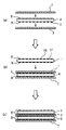
部分接着層8が形成された正極1と、全面接着層9が形成された負極4は、図4(a)に示すように、まず、負極4の両面にセパレータ7を重ね、さらに、セパレータ7のうえに正極1を重ねる。このように、順次、負極4と正極1とをセパレータを介して交互に積み重ね、加圧乾燥して、積層型の発電要素が製作される。
【0027】
以上に示した実施の形態では、正極1に部分接着層8を形成し、負極4には全面接着層を形成したが、正極1および負極4の両方の極に部分接着層8を形成してもよい。この場合、図5(a)に示すように、まず、負極4の両面にセパレータ7を重ね、さらに、図5(b)および(c)に示すように、セパレータ7の上に正極1を重ねる。このように、順次、負極4と正極1とをセパレータを介して交互に積み重ね、加圧乾燥して、図6に示すような、積層型の発電要素を製作する。
【0028】
また、正極1または負極4のいずれか一方に部分接着層を形成してセパレータと接合し、他方には接着層を形成せず、セパレータと接合しない構成でもよい。
【0029】
また、部分接着層8の形成に用いるロールは、図7の側面図(a)および平面図(b)に示すように、斜めの線状の凹凸が形成されたグラビアロール16の他、平行な線状の凹凸が形成されたグラビアロールなど種々の形状の凹凸が形成されたグラビアロールを用いることができる。
【0030】
上記発電要素は、図8に示すように、バリア性を有するアルミラミネートシート17で覆い、まず一辺を残して周囲を封口する。この際、発電要素18の各正極と各負極にそれぞれリード19が接続され、リード19はアルミラミネートシート17を重ね合わせた間から先端部を突出させた状態で確実に封口する。
【0031】
次に、アルミラミネートシート17をチャンバー内に収容する等して真空引きすることにより、発電要素18の内部から空気を引き抜き、アルミラミネートシート17内に非水電解液を注入する。そして、リード19を介して予備充電を行うことにより電極間にガスを発生させてから、再度真空引きしてこのガスを引き抜き、その後アルミラミネートシート17を完全に封口し内部を密封することによりリチウムイオン電池を完成する。
【0032】
本実施の形態のリチウムイオン電池は、正極1および負極4とセパレータ7とを固着して一体化することにより、発電要素18をテープ等で止め付けたり金属容器等に収納して圧迫しなくても、電極1,4間の間隔、距離の変化や、電極1,4とセパレータ7の重なりのずれを抑えることができ、柔軟なアルミラミネートシート17内に収納することが可能となる。
【0033】
また、本実施の形態のリチウムイオン電池は、最初の充電時にのみ正極間からガスが発生するので、アルミラミネートシートを完全に封口する前に予備充電を行ってガスを予め抜く工程を要する。
【0034】
上記のように、発電要素18の電極1,4とセパレータ7との間が接着剤によって固着されているものは、本来、非水電解液を注入した際に、正極1、負極4とセパレータ7との間から非水電解液が発電要素18の内部に浸入することができず、また、セパレータ7は、微多孔性樹脂フイルム等を用いるので、不織布等に比べて非水電解液が染み込みにくい。
【0035】
しかし、正極1、負極4とセパレータ7の間に形成される部分接着層8により、連続につながる空隙が形成されているので、非水電解液は発電要素18の側面に開口するこれらの連続空隙層を伝わって内部に入り込み、これら周囲の正極1、負極4内の空孔中やセパレータ7空孔中に迅速に浸透することができる。
【0036】
また、非水電解液を注入する前の真空引きの際や予備充電後の真空引きの際にも、発電要素18の内部の空気や予備充電で発生したガスが連続空隙層を通って迅速に引き抜くことができるようになる。
【0037】
また、正極1、負極4とセパレータ7とを接着剤で接着し乾燥させる際にも、連続空隙層があるために、接着剤の溶媒を迅速に揮発させることができるようになる。
【0038】
また、部分接着層8の接着部10と未接着部11が形成するパターンは200メッシュより粗いことによって、上記効果はより一層顕著になる。
【0039】
以上説明したように、本実施の形態のリチウムイオン電池によれば、発電要素18内への非水電解液の拡散速度が向上すると共に、発電要素18内からガス抜きを迅速に行うことができるようになるので、非水電解液の注入作業や真空引きの作業時間を短縮して生産性を向上させることができる。
【0040】
また、このように非水電解液の拡散、ガス抜きや溶剤の乾燥速度が迅速に行われることにより、電極とセパレータとを固着して発電要素を一体化しても、生産性が低下するようなことがなくなるので、この発電要素を柔軟なアルミラミネートシート内に収納して、電池容器を肉厚が薄く軽量で安価なものとすることができる。
【0041】
なお、上記実施形態では発電要素をアルミラミネートシート内に収納する場合について説明したが、これに限らず、他の柔軟なシート状の電池容器に収納してもよく、金属缶等からなる堅牢な電池容器に収納しても良い。
【0042】
また、上記実施の形態では正極1、負極4の間にセパレータ7を介して重ねた積層型の発電要素で説明を行ったが、正極1と負極4の間にセパレータ7を介して巻いた巻き型の発電要素や、これを楕円状に巻いた楕円状の巻き型の発電要素でも、正極1と負極4の間にセパレータ7を介して折り畳んだ折り畳み型発電要素でもよい。
【0043】
また、上記実施の形態では、リチウムイオン電池について説明したが、本発明は、これに限らず一次電池や他の二次電池にも同様に実施することができる。そして、正極と負極とセパレータの構成も、これら電池の種類等に応じて任意に変更することができる。
【0044】
また、本実施の形態の部分接着層と電極の溝形成とを併用してもよい。
【0045】
【実施例】
実施例1.
正極は、厚さ20μmのアルミニウム箔からなる正極集電板の両面に、正極活物質としてリチウムコバルト複合酸化物(LiCoO2)を90重量部と導電剤として人造黒鉛を6重量部と結着剤としてポリフッ化ビニリデン(PVDF)を4重量部に溶剤としてN−メチルピロリドン(NMP)を適当量加えたものからなる正極合剤ペーストをそれぞれ塗布し乾燥させることにより、正極活物質層を形成して作製した。この正極をロールプレス機にかけて最終厚み160μmとし、これを幅100mm、長さ150mmに切断して正極とした。
【0046】
負極は、厚さ15μmの銅箔からなる負極集電体の両面にグラファイト90重量部と、結着剤としてPVDF10重量部にNMP(溶剤)を適当量加えたものとからなる負極合剤ペーストをそれぞれ塗布し、乾燥させることにより負極活物質層を形成して作製した。この負極をロールプレス機にかけて最終厚み160μmの負極シートとし、これを幅105mm、長さ155mmに切断して負極とした。
【0047】
セパレータは厚み25μmのポリエチレン製微多孔性樹脂フイルムのシートを幅110mm、長さ160mmに切断して用意した。
【0048】
これらの正極および負極とセパレータとを固着させる接着剤として、PVDF樹脂をNMPに溶かした溶液に平均粒径0.01μmのアルミナ粉末を分散させた接着剤ペーストを作製した。
【0049】
得られた負極の両面に、図3に示した平滑なロール15を用いて、均一な厚みの接着剤を塗布し、全面接着層を形成し、この負極の両側にセパレーターを張り合わせた。
【0050】
正極には、図2に示したグラビアロール12を用いて部分接着層を形成した。本実施例で用いたロールのグラビアパターンは、40メッシュである。
【0051】
次に、先にセパレータを張り合わせた負極のセパレータ上に、部分接着層を形成した正極を重ね合わせ、以上のような接着剤塗布と張り合わせの繰り返しにより、所定枚数の電池を積層した。
【0052】
その後、80℃に設定した真空乾燥機中で加圧しながら乾燥を開始した。乾燥中には、両極板間の電気抵抗を測定し、その抵抗値が100MΩを越えた時点で乾燥を終了させた。以上のような方法で、全面接着層と部分接着層を有する積層型発電要素を得た。
【0053】
上記作製した積層型発電要素にリードをスポット溶接機で取り付けた後、三辺を熱融着させて袋状にした幅140mm、長さ200mmのアルミラミネートシートの袋に入れて、6フッ化リン酸リチウム(LiPF6)を1mol/l含むエチレンカーボネート(EC)とジエチルカーボネート(DEC)の1:1溶液からなる電解液を適当量注入した。これを真空に引いて電解液を真空含浸させた後、予備充電を行い、発生したガスを引き抜いてから、熱融着機で残る一辺を封口して積層型電池とした。
【0054】
この電池を充電した後、85℃に設定されたオーブンに入れ、電池包装材であるアルミラミネートパックの膨れを確認する高温保存試験を行った。
【0055】
この電池の接着剤乾燥所要時間は、およそ30分であった。また高温保存試験では、電池の膨れは、見られなかった。
【0056】
実施例2.
実施例1と同様に、負極及び正極を作製し、作製した負極および正極の両面にそれぞれ、実施例1の塗布方法と同様の40メッシュのグラビアロールを用いて点状の部分接着層を形成した。
【0057】
その後は、実施例1と全く同様に、積層型発電要素を組み上げ、乾燥させ、また、アルミラミネートシートの袋に入れ、電解液の注入、予備充電によるガス抜きを同様に行った。また、同様に電池の封口を行い、高温保存試験を行った。
【0058】
この電池の接着剤乾燥の所要時間は、およそ35分であった。また高温保存試験では、電池の膨れは、見られなかった。
【0059】
比較例1.
実施例1と同様に負極及び正極を作製し、作製した負極および正極の両面にそれぞれ、図3に示した平滑ロールを用いて全面接着層を形成した。全面接着層を形成した負極および正極とセパレータとを実施例1と同様に組立て、積層型発電要素を作製した。また、乾燥、電解液注入、予備充電によるガス抜きを行い、さらに、電池の封口を行い、高温保存試験を行った。
【0060】
この電池の接着剤乾燥の所要時間は、およそ120分であった。また高温保存試験では、明らかな電池の膨れが確認された。
【0061】
実施例3.
実施例1と同様に、負極及び正極を作製した。作製した負極の両面に、実施例1と同様、平滑ロールを用いて、全面接着層を形成し、セパレータを張り合わせて負極を作製した。正極の両面に、100メッシュのグラビアロールで、点状の部分接着層を形成し、この正極を先にセパレータを張り合わせた負極のセパレータ上に重ね合わせ、以上のような接着剤塗布と張り合わせの繰り返しにより、所定枚数の電池を積層した。
【0062】
その後、実施例2と全く同様に、積層型発電要素を組み上げ、乾燥させ、アルミラミネートシートに入れ、電解液の注入や、予備充電によるガス抜き、電池の封口を行い、高温保存試験を行った。
【0063】
この電池の接着剤乾燥の所要時間は、およそ40分であった。また、高温保存試験では、電池の膨れは、見られなかった。
【0064】
実施例4.
実施例1と同様に、負極及び正極を作製した。実施例3と同様に、平滑ロールを用いて、負極に全面接着層を形成し、正極には200メッシュのグラビアロールを用いて、点状の部分接着層を形成した。その他は、実施例3と全く同様にして、積層型発電要素を組み上げ、乾燥させ、アルミラミネートシートに入れ、電解液の注入や、予備充電によるガス抜き、電池の封口を同様に行い、高温保存試験を行った。
【0065】
この電池の接着剤乾燥の所要時間は、およそ100分であった。また高温保存試験では、若干の電池の膨れが確認されたが、実用状問題ない程度であった。
【0066】
実施例5.
実施例1と同様に、負極及び正極を作製した。負極および正極それぞれの両面に、図7に示した、斜めに線状の凹凸があるグラビアロール16を用いて、部分接着層を形成し、その他は実施例1と同様にして、電池を作製し、高温保存試験を行った。
【0067】
この電池の接着剤乾燥所要時間は、およそ30分であった。また高温保存試験では、電池の膨れは、見られなかった。
【0068】
実施例6.
実施例1と同様に、負極及び正極を作製した。負極の両面に、実施例1と同様に、平滑ロールを用いて、全面接着層を形成し、正極の両面に実施例5と同様に斜めに線状の凹凸があるグラビアロール16を用いて、部分接着層を形成した。その他は、実施例1と同様にして、電池を作製し、高温保存試験を行った。
【0069】
この電池の接着剤乾燥所要時間は、およそ40分であった。また高温保存試験では、電池の膨れは、見られなかった。
【0070】
以上、実施例1〜6および比較例の結果を表1にまとめて示す。
【0071】
【表1】

実施例1〜6では、乾燥所要時間がすべて比較例に比べて短く、生産性が向上することがわかる。負極、正極の少なくとも一方を部分接着させれば、全面接着された電極側からも、セパレータを介して対向する部分接着層に生じた未接着部の空隙を通ってガスが抜けるため、乾燥時間が短縮されたものと考えられる。
【0073】
実施例5では、一方を200メッシュのグラビアロールにて接着したにもかかわらず、比較的長時間の乾燥を要した。これは、グラビアのメッシュが細かすぎるため、隣り合う部分接着部同士がつながり、連続空隙層が少なくなったためと思われる。
【0074】
また、部分接着のパターンとして、点状及び線状を実施したが、同様の効果が示された。
【0075】
高温保存試験では、接着乾燥時間が比較的長いもので、電池の膨れが確認された。これは前述の乾燥時間の差が生じる理由と同様に、連続空隙層の有無、多少により差が生じたものと思われる。
【0076】
連続空隙層があると、電解液注入時には発電要素全体に電解液が侵入し易くなり、また、予備充電時には、ガスが抜けやすくなる。連続空隙層が無い場合、発電要素が充分に電解液に濡れず、予備充電された際にも、発電要素に付着した不純物の分解が確実に行われない。また、連続空隙層が無いと、分解したガスが抜けにくく、抜けずに残った分解ガスが電池の膨れを招いている可能性もある。いずれの理由にしても、連続空隙層の存在により、高温保存しても膨れの生じない電池が得られたものと推察される。
【0077】
なお、部分接着層の厚みは、本発明の効果を発揮するために、少なくとも電極のポア径よりは大きい必要があるが、あまり大きすぎると電極間距離が大きくなるため、内部抵抗が上昇し、電池特性が低下する。このため、電池の種類により生産性と機能性の両面から最適化を行う必要がある。
【0078】
【発明の効果】
本発明の第1および第2の電池によれば、正および負の電極が電解質層を介して交互に配置され、少なくとも一方の電極が接着層を介して電解質層と接合された発電要素を備えた電池において、上記接着層の少なくとも一つが、上記電極と電解質層とを部分的に接合するメッシュ状に配列された点状の接着部と上記点状の接着部間の未接着部に形成された空隙とを有し、この空隙が上記電極の端部に連通している部分接着層であり、上記接着部の配列パターンが200メッシュより小さいので、接着剤を塗布し、積層した後の乾燥時に、気化する溶剤を電池要素体から効率的に排出することが可能となり、乾燥時間が大幅に短縮される。
【0079】
また、電解液の注入や、その後の電池内のガス抜きも効率よく行える効果がある。
【0080】
さらに、高温保存による電池の膨れを防ぐことが容易となる。
【0081】
本発明の第3の電池によれば、接着層が、溶媒に溶解する接着性樹脂により形成されたものであるので、加熱乾燥することによって、乾燥工程の時間を短縮することができる。
【0082】
本発明の第4の電池によれば、接着層が、フィラーを含むものであるので、電解質層と電極との界面のイオン伝導度を大きくし、電池の特性を向上させることができる。
【0083】
本発明の第5の電池によれば、電解質層の電解質がリチウムイオンを含む有機電解質であるものであり、電池内のガス抜き、高温保存による電池の膨れ防止が重要なリチウムイオン電池に有効である。
【0084】
本発明の第1の電池の製造方法によれば、正および負の電極を電解質層を介して交互に配置し、上記電極の少なくとも一方を接着層を介して電解質層と接合した発電要素を備えた電池の製造方法において、上記接着層の少なくとも一つを、表面に200メッシュより小さい点状に配列された凹部が形成された金型を用い、この金型の凹部に溜めた接着剤を電極上に転写して点状の接着部と上記点状の接着部間の未接着部の空隙とを形成し、点状の接着部と未接着部の空隙とからなるパターンを形成し、上記空隙が上記電極の端部に連通するように形成するものであるので、乾燥時間、電解液の注入、その後の電池内のガス抜きの時間を短縮し、高温保存による電池の膨れを防止することができる。
【図面の簡単な説明】
【図1】 本発明の電池の一実施の形態を示す断面模式図である。
【図2】 本発明の電池の一実施の形態の電池を製造する装置を模式的に示す側面図(a)および平面図(b)である。
【図3】 本発明の電池の一実施の形態の電池を製造する装置を模式的に示す側面図(a)および平面図(b)である。
【図4】 本発明の電池の一実施の形態の電池を組み立てる方法を示す断面図である。
【図5】 本発明の電池の他の実施の形態の電池を組み立てる方法を示す断面図である。
【図6】 本発明の電池の他の実施の形態を示す断面模式図である。
【図7】 本発明の電池の他の実施の形態の電池を製造する装置を模式的に示す側面図(a)および平面図(b)である。
【図8】 アルミラミネートシートで封口された電池を示す斜視図である。
【符号の説明】
1 正極、2 正極活物質層、3 正極集電体、4 負極、5 負極活物質層、6 負極集電体、7 セパレータ、8 部分接着層、9 全面接着層、10 接着部分、11 未接着部分、12,16 グラビアロール、13 接着剤、14 ブレード、15 平滑ロール、17 アルミラミネートシート、18 発電要素、19 リード。[0001]
BACKGROUND OF THE INVENTION
The present invention relates to a battery including a power generation element in which positive and negative electrodes are alternately arranged via an electrolyte holding layer for holding an electrolyte such as a separator, and a method for manufacturing the same.
[0002]
[Prior art]
In general, a chemical battery such as a primary battery or a secondary battery is composed of a power generation element in which positive and negative electrodes are arranged close to each other through a separator or the like that plays a role of holding an electrolyte or an insulating film. For example, in a wound battery, a cylindrical power generation element is formed by winding a separator between a pair of positive and negative electrodes. A stacked battery forms a power generation element by laminating a plurality of positive and negative electrodes with a separator between them. These power generation elements are housed in a case and pressed from the outside to maintain the adhesion between the positive and negative electrodes, thereby preventing misalignment and increase in resistance. In addition, there is a battery in which the positive and negative electrodes of the power generation element and the separator are joined with an electrolyte-retaining resin or the like to maintain adhesion without being pressed from the outside (for example, US Pat. No. 5,512,389). No., US Pat. No. 5,741,609).
[0003]
However, if the electrode bodies are brought into close contact with each other by external compression or internal bonding as in the prior art, there is almost no gap between the electrodes, and when the electrolyte is injected, the electrolyte is applied to the entire power generating element. It took some time to soak up. As a method for solving this problem, International Publication No. WO9,848,466 discloses a method of providing grooves on the electrode surface. According to this method, by forming the groove reaching the end of the electrode, it is possible to increase the rate of penetration of the electrolytic solution, the rate of venting the gas generated inside, and the rate of evaporation of the solvent for adhesion.
[0004]
[Problems to be solved by the invention]
When the groove reaching the end of the electrode is formed, the groove portion may be damaged or may be cut when the damage is severe. In addition, since a grooving process is required, this is a factor that increases the manufacturing cost.
[0005]
The present invention has been made to solve the above-mentioned problems, and it is not necessary to groove the electrodes, and it is possible to increase the injection rate of the electrolytic solution, the degassing rate, and the drying rate of the solvent. It is the purpose.
[0006]
[Means for Solving the Problems]
A first battery of the present invention is a battery including a power generation element in which positive and negative electrodes are alternately arranged via an electrolyte layer, and at least one electrode is joined to the electrolyte layer via an adhesive layer. At least one of the adhesive layers partially joins the electrode and the electrolyte layer Between the dot-shaped adhesive portions arranged in a mesh and the above-mentioned dot-shaped adhesive portions Formed voids When And this gap is a partial adhesive layer communicating with the end of the electrode. That is, the arrangement pattern of the bonded portions is smaller than 200 mesh. Is.
[0007]
According to a second battery of the present invention, in the first battery, both the positive and negative electrodes are joined to the electrolyte layer via an adhesive layer, one adhesive layer is the partial adhesive layer, and the other This adhesive layer is a full-surface adhesive layer that joins the electrode and the electrolyte layer over the entire surface.
[0008]
Of the present invention Third The battery is the first battery, the above The adhesive layer is formed of an adhesive resin that dissolves in a solvent.
[0009]
Of the present invention 4th In the battery according to the first battery, the adhesive layer includes a filler.
[0010]
Of the present invention 5th The battery is the first battery in which the electrolyte of the electrolyte layer is an organic electrolyte containing lithium ions.
[0011]
A first battery manufacturing method according to the present invention includes a power generation element in which positive and negative electrodes are alternately arranged via an electrolyte layer, and at least one of the electrodes is joined to the electrolyte layer via an adhesive layer. In the manufacturing method, at least one of the adhesive layers is applied to the surface. Recesses arranged like dots smaller than 200 mesh were formed Using a mold, transfer the adhesive accumulated in the recess of this mold onto the electrode. Dot-bonded parts and gaps between unbonded parts between the above-mentioned point-shaped bonded parts Forming, The gap is It forms so that it may connect with the edge part of the said electrode.
[0012]
DETAILED DESCRIPTION OF THE INVENTION
Embodiments of the present invention will be described focusing on lithium-ion batteries that are actively developed mainly for portable devices.
[0013]
FIG. 1 is a cross-sectional view showing an embodiment of the battery of the present invention. In the figure, 1 is a square positive electrode, 2 is a positive electrode active material layer, 3 is a square positive electrode current collector plate, and the positive electrode
[0014]
[0015]
7 is a separator, 8 is a partial adhesive layer, and 9 is a full-surface adhesive layer. The partial
[0016]
The
[0017]
Further, in the lithium ion battery of this embodiment, since the
[0018]
The
[0019]
The adhesive used for the partial
[0020]
Moreover, the ion conductivity between the
[0021]
The
[0022]
The
[0023]
As the
[0024]
The partial
[0025]
Using the
[0026]
As shown in FIG. 4A, the
[0027]
In the embodiment described above, the partial
[0028]
Alternatively, a configuration may be employed in which a partial adhesive layer is formed on one of the
[0029]
In addition, as shown in the side view (a) and the plan view (b) of FIG. 7, the roll used for forming the partial
[0030]
As shown in FIG. 8, the power generation element is covered with an
[0031]
Next, the
[0032]
In the lithium ion battery of the present embodiment, the
[0033]
Moreover, since the lithium ion battery of this Embodiment generate | occur | produces gas between positive electrodes only at the time of the first charge, it requires the process of performing preliminary charge and degassing before sealing an aluminum laminate sheet completely.
[0034]
As described above, what is fixed between the
[0035]
However, since continuous voids are formed by the partial
[0036]
In addition, when evacuating before injecting the non-aqueous electrolyte or evacuating after precharging, the air inside the
[0037]
Further, when the
[0038]
In addition, since the pattern formed by the bonded
[0039]
As described above, according to the lithium ion battery of the present embodiment, the diffusion rate of the non-aqueous electrolyte into the
[0040]
In addition, the diffusion of the non-aqueous electrolyte, the degassing, and the drying rate of the solvent are performed quickly, so that the productivity is lowered even if the electrode and the separator are fixed and the power generation element is integrated. Therefore, the power generation element can be housed in a flexible aluminum laminate sheet, and the battery container can be made thin, light and inexpensive.
[0041]
In addition, although the said embodiment demonstrated the case where an electric power generation element was accommodated in an aluminum laminate sheet, it is not restricted to this, It may be accommodated in another flexible sheet-like battery container, and it is a robust thing consisting of a metal can etc. You may store in a battery container.
[0042]
Further, in the above embodiment, the description has been given of the laminated power generation element in which the
[0043]
Moreover, in the said embodiment, although the lithium ion battery was demonstrated, this invention can be similarly implemented not only to this but a primary battery and another secondary battery. And the structure of a positive electrode, a negative electrode, and a separator can also be arbitrarily changed according to the kind etc. of these batteries.
[0044]
Moreover, you may use together the partial adhesion layer and groove | channel formation of an electrode of this Embodiment.
[0045]
【Example】
Example 1.
The positive electrode has a lithium cobalt composite oxide (LiCoO) as a positive electrode active material on both surfaces of a positive electrode current collector plate made of an aluminum foil having a thickness of 20 μm. 2 ) 90 parts by weight, 6 parts by weight of artificial graphite as a conductive agent, 4 parts by weight of polyvinylidene fluoride (PVDF) as a binder, and a suitable amount of N-methylpyrrolidone (NMP) as a solvent. Each of the agent pastes was applied and dried to form a positive electrode active material layer. This positive electrode was subjected to a roll press machine to a final thickness of 160 μm, which was cut into a width of 100 mm and a length of 150 mm to obtain a positive electrode.
[0046]
For the negative electrode, a negative electrode mixture paste consisting of 90 parts by weight of graphite on both sides of a negative electrode current collector made of copper foil with a thickness of 15 μm and a suitable amount of NMP (solvent) added to 10 parts by weight of PVDF as a binder. Each was coated and dried to form a negative electrode active material layer. This negative electrode was subjected to a roll press to obtain a negative electrode sheet having a final thickness of 160 μm, which was cut into a width of 105 mm and a length of 155 mm to obtain a negative electrode.
[0047]
The separator was prepared by cutting a polyethylene microporous resin film sheet having a thickness of 25 μm into a width of 110 mm and a length of 160 mm.
[0048]
As an adhesive for fixing the positive electrode and the negative electrode to the separator, an adhesive paste was prepared by dispersing alumina powder having an average particle diameter of 0.01 μm in a solution obtained by dissolving PVDF resin in NMP.
[0049]
An adhesive having a uniform thickness was applied to both surfaces of the obtained negative electrode using the
[0050]
A partial adhesive layer was formed on the positive electrode using the
[0051]
Next, the positive electrode on which the partial adhesive layer was formed was superposed on the negative electrode separator to which the separator was previously bonded, and a predetermined number of batteries were laminated by repeating the adhesive application and bonding described above.
[0052]
Thereafter, drying was started while applying pressure in a vacuum dryer set to 80 ° C. During the drying, the electrical resistance between the bipolar plates was measured, and the drying was terminated when the resistance value exceeded 100 MΩ. By the method as described above, a laminated power generation element having a whole surface adhesive layer and a partial adhesive layer was obtained.
[0053]
After attaching the lead to the above-mentioned laminated power generation element with a spot welder, heat-sealing three sides into a bag-like aluminum laminated sheet bag having a width of 140 mm and a length of 200 mm, and phosphorus hexafluoride Lithium acid (LiPF 6 An appropriate amount of an electrolytic solution composed of a 1: 1 solution of ethylene carbonate (EC) and diethyl carbonate (DEC) containing 1 mol / l) was injected. This was evacuated and impregnated with an electrolyte solution, and then precharged. After the generated gas was extracted, the remaining side was sealed with a heat-sealing machine to obtain a laminated battery.
[0054]
After charging this battery, it was placed in an oven set at 85 ° C., and a high temperature storage test was performed to confirm the swelling of the aluminum laminate pack as the battery packaging material.
[0055]
The battery took about 30 minutes to dry the adhesive. Further, in the high temperature storage test, the battery did not swell.
[0056]
Example 2
In the same manner as in Example 1, a negative electrode and a positive electrode were produced, and dot-like partial adhesion layers were formed on both surfaces of the produced negative electrode and positive electrode using a 40 mesh gravure roll similar to the coating method of Example 1, respectively. .
[0057]
Thereafter, in the same manner as in Example 1, the laminated power generation element was assembled, dried, put into an aluminum laminate sheet bag, and the electrolyte was injected and degassed by precharging in the same manner. Similarly, the battery was sealed and a high temperature storage test was conducted.
[0058]
The time required for drying the adhesive of this battery was approximately 35 minutes. Further, in the high temperature storage test, the battery did not swell.
[0059]
Comparative Example 1
A negative electrode and a positive electrode were produced in the same manner as in Example 1, and an entire surface adhesive layer was formed on both surfaces of the produced negative electrode and positive electrode using the smooth rolls shown in FIG. A negative electrode having a full-surface adhesive layer, a positive electrode, and a separator were assembled in the same manner as in Example 1 to produce a laminated power generation element. Moreover, degassing by drying, electrolyte solution injection, and preliminary charging was performed, the battery was further sealed, and a high temperature storage test was performed.
[0060]
The time required for drying the adhesive of this battery was approximately 120 minutes. In the high-temperature storage test, clear battery swelling was confirmed.
[0061]
Example 3
In the same manner as in Example 1, a negative electrode and a positive electrode were produced. Similar to Example 1, a smooth roll was used to form a whole surface adhesive layer on both sides of the produced negative electrode, and a separator was laminated to produce a negative electrode. A dot-like partial adhesive layer is formed on both surfaces of the positive electrode with a 100 mesh gravure roll, and this positive electrode is overlaid on the negative electrode separator to which the separator is first bonded, and the above-described adhesive application and bonding are repeated. Thus, a predetermined number of batteries were stacked.
[0062]
Thereafter, in exactly the same manner as in Example 2, the laminated power generation element was assembled, dried, placed in an aluminum laminate sheet, injected with an electrolyte, degassed by precharging, and sealed in a battery, and a high temperature storage test was performed. .
[0063]
The time required for drying the adhesive of this battery was approximately 40 minutes. Further, in the high temperature storage test, the battery did not swell.
[0064]
Example 4
In the same manner as in Example 1, a negative electrode and a positive electrode were produced. As in Example 3, a smooth adhesive roll was used to form an entire adhesive layer on the negative electrode, and a 200 mesh gravure roll was used to form a dot-like partial adhesive layer on the positive electrode. Others are the same as in Example 3, the laminated power generation element is assembled, dried, put into an aluminum laminate sheet, injected with electrolyte, degassed by precharging, and sealed in the same manner, and stored at high temperature. A test was conducted.
[0065]
The time required for drying the adhesive of this battery was approximately 100 minutes. Further, in the high-temperature storage test, some swelling of the battery was confirmed, but there was no practical problem.
[0066]
In the same manner as in Example 1, a negative electrode and a positive electrode were produced. A partial adhesive layer was formed on both surfaces of the negative electrode and the positive electrode using the
[0067]
The battery took about 30 minutes to dry the adhesive. Further, in the high temperature storage test, the battery did not swell.
[0068]
Example 6
In the same manner as in Example 1, a negative electrode and a positive electrode were produced. A smooth adhesive roll is used to form both sides of the negative electrode in the same manner as in Example 1, and a
[0069]
The battery took about 40 minutes to dry the adhesive. Further, in the high temperature storage test, the battery did not swell.
[0070]
The results of Examples 1 to 6 and the comparative example are summarized in Table 1 above.
[0071]
[Table 1]
In Examples 1-6, it turns out that all the drying required time is short compared with a comparative example, and productivity improves. If at least one of the negative electrode and the positive electrode is partially bonded, the gas escapes from the entire bonded surface of the electrode through the voids of the non-bonded portions formed in the facing partially bonded layer via the separator. It is thought that it was shortened.
[0073]
In Example 5, although one side was bonded with a 200 mesh gravure roll, drying for a relatively long time was required. This is presumably because the gravure mesh was too fine and the adjacent partially bonded portions were connected to each other, so that the continuous void layer was reduced.
[0074]
Moreover, although the dot form and the linear form were implemented as a pattern of partial adhesion | attachment, the same effect was shown.
[0075]
In the high-temperature storage test, the adhesion drying time was relatively long, and the battery was swollen. This seems to be due to the presence or absence of the continuous void layer and the difference as well as the reason for the difference in the drying time described above.
[0076]
When there is a continuous void layer, the electrolyte easily enters the entire power generating element when the electrolyte is injected, and gas is easily released during the preliminary charging. When there is no continuous void layer, the power generation element is not sufficiently wetted with the electrolyte, and even when pre-charged, impurities attached to the power generation element are not reliably decomposed. Further, if there is no continuous void layer, it is difficult for the decomposed gas to escape, and the decomposed gas remaining without being released may cause the battery to swell. For any reason, it is presumed that a battery that does not swell even when stored at a high temperature was obtained due to the presence of the continuous void layer.
[0077]
The thickness of the partial adhesive layer needs to be at least larger than the pore diameter of the electrode in order to exert the effect of the present invention, but if it is too large, the distance between the electrodes becomes large, so that the internal resistance increases. Battery characteristics deteriorate. For this reason, it is necessary to optimize from both aspects of productivity and functionality depending on the type of battery.
[0078]
【The invention's effect】
According to the first and second batteries of the present invention, the battery includes the power generation element in which the positive and negative electrodes are alternately arranged via the electrolyte layer, and at least one of the electrodes is joined to the electrolyte layer via the adhesive layer. In the battery, at least one of the adhesive layers partially joins the electrode and the electrolyte layer. Non-adhered part between the dotted adhesive parts arranged in a mesh and the above-mentioned dotted adhesive parts Void formed in When And this gap is a partial adhesive layer communicating with the end of the electrode. That is, the arrangement pattern of the bonded portions is smaller than 200 mesh. Therefore, it is possible to efficiently discharge the solvent to be vaporized from the battery element body when drying after applying and laminating the adhesive, and the drying time is greatly shortened.
[0079]
Further, there is an effect that the injection of the electrolytic solution and the subsequent degassing of the battery can be efficiently performed.
[0080]
Furthermore, it becomes easy to prevent the battery from swelling due to high temperature storage.
[0081]
Of the present invention Third According to the battery, since the adhesive layer is formed of an adhesive resin that dissolves in the solvent, the time for the drying process can be shortened by heating and drying.
[0082]
According to the fourth battery of the present invention, since the adhesive layer contains a filler, the ionic conductivity at the interface between the electrolyte layer and the electrode can be increased, and the characteristics of the battery can be improved.
[0083]
Of the present invention 5th According to the battery, the electrolyte of the electrolyte layer is an organic electrolyte containing lithium ions, which is effective for a lithium ion battery in which degassing of the battery and prevention of battery swelling due to high temperature storage are important.
[0084]
According to the first battery manufacturing method of the present invention, the power generation element is provided in which the positive and negative electrodes are alternately arranged via the electrolyte layer, and at least one of the electrodes is joined to the electrolyte layer via the adhesive layer. In the method of manufacturing a battery, at least one of the adhesive layers is provided on the surface. Recesses arranged in a dot shape smaller than 200 mesh Using the mold formed with, transfer the adhesive accumulated in the recess of this mold onto the electrode Dot-bonded parts and gaps between unbonded parts between the above-mentioned point-shaped bonded parts Forming, A pattern consisting of dotted adhesive and non-adhered gaps Forming, So that the gap communicates with the end of the electrode. Since it is formed, the drying time, the injection of the electrolyte, and the subsequent degassing time in the battery can be shortened, and the battery can be prevented from swelling due to high temperature storage.
[Brief description of the drawings]
FIG. 1 is a schematic cross-sectional view showing an embodiment of a battery of the present invention.
FIG. 2 is a side view (a) and a plan view (b) schematically showing an apparatus for producing a battery according to an embodiment of the battery of the present invention.
FIG. 3 is a side view (a) and a plan view (b) schematically showing an apparatus for producing a battery according to an embodiment of the battery of the present invention.
FIG. 4 is a cross-sectional view showing a method for assembling a battery according to an embodiment of the battery of the present invention.
FIG. 5 is a cross-sectional view showing a method of assembling a battery according to another embodiment of the battery of the present invention.
FIG. 6 is a schematic cross-sectional view showing another embodiment of the battery of the present invention.
FIG. 7 is a side view (a) and a plan view (b) schematically showing an apparatus for producing a battery according to another embodiment of the battery of the present invention.
FIG. 8 is a perspective view showing a battery sealed with an aluminum laminate sheet.
[Explanation of symbols]
DESCRIPTION OF
Claims (6)
Priority Applications (1)
| Application Number | Priority Date | Filing Date | Title |
|---|---|---|---|
| JP2000195356A JP3745593B2 (en) | 2000-06-29 | 2000-06-29 | Battery and manufacturing method thereof |
Applications Claiming Priority (1)
| Application Number | Priority Date | Filing Date | Title |
|---|---|---|---|
| JP2000195356A JP3745593B2 (en) | 2000-06-29 | 2000-06-29 | Battery and manufacturing method thereof |
Publications (3)
| Publication Number | Publication Date |
|---|---|
| JP2002015773A JP2002015773A (en) | 2002-01-18 |
| JP2002015773A5 JP2002015773A5 (en) | 2005-11-04 |
| JP3745593B2 true JP3745593B2 (en) | 2006-02-15 |
Family
ID=18694029
Family Applications (1)
| Application Number | Title | Priority Date | Filing Date |
|---|---|---|---|
| JP2000195356A Expired - Fee Related JP3745593B2 (en) | 2000-06-29 | 2000-06-29 | Battery and manufacturing method thereof |
Country Status (1)
| Country | Link |
|---|---|
| JP (1) | JP3745593B2 (en) |
Families Citing this family (21)
| Publication number | Priority date | Publication date | Assignee | Title |
|---|---|---|---|---|
| JP4526352B2 (en) | 2004-11-08 | 2010-08-18 | 日東電工株式会社 | Reactive polymer-supported porous film for battery separator and battery manufacturing method using the same |
| JP5401756B2 (en) * | 2006-11-28 | 2014-01-29 | 日産自動車株式会社 | Secondary battery |
| JP5347815B2 (en) * | 2009-08-05 | 2013-11-20 | 日産自動車株式会社 | Thin battery manufacturing method and thin battery |
| JP5578282B2 (en) * | 2011-06-28 | 2014-08-27 | 株式会社村田製作所 | Electric storage device and manufacturing method thereof |
| KR20150032895A (en) | 2012-07-18 | 2015-03-30 | 스미또모 가가꾸 가부시키가이샤 | Adhesive layer, layer and composition |
| WO2014021292A1 (en) * | 2012-07-30 | 2014-02-06 | 帝人株式会社 | Separator for non-aqueous electrolyte battery, and non-aqueous electrolyte battery |
| KR101676446B1 (en) * | 2013-09-30 | 2016-11-15 | 주식회사 엘지화학 | Method for manufacturing a separator for lithium secondary battery, the separator manufactured by the method and lithium secondary battery including the same |
| JP6296260B2 (en) * | 2013-11-04 | 2018-03-20 | エルジー・ケム・リミテッド | Method for forming adhesive layer for secondary battery |
| WO2015083389A1 (en) * | 2013-12-06 | 2015-06-11 | Necエナジーデバイス株式会社 | Lithium ion secondary battery |
| KR101590997B1 (en) | 2014-01-13 | 2016-02-02 | 주식회사 엘지화학 | Battery Cell Comprising Electrode Assembly Coated with Inactive Particles |
| US10090492B2 (en) * | 2014-01-13 | 2018-10-02 | Lg Chem, Ltd. | Battery cell with safety improved using inert particles |
| JP6404577B2 (en) * | 2014-02-27 | 2018-10-10 | マクセルホールディングス株式会社 | Non-aqueous electrolyte secondary battery and manufacturing method thereof |
| KR101977639B1 (en) * | 2016-02-16 | 2019-05-14 | 주식회사 엘지화학 | Electrode assembly and manufacturing method of thereof |
| EP3573163B1 (en) * | 2017-01-20 | 2023-06-28 | Envision AESC Japan Ltd. | Method for manufacturing mono cell |
| JP6989265B2 (en) | 2017-01-27 | 2022-01-05 | トヨタ自動車株式会社 | Battery manufacturing method |
| WO2018154777A1 (en) * | 2017-02-27 | 2018-08-30 | 日産自動車株式会社 | Method for producing mono-cell |
| JP6760193B2 (en) * | 2017-04-20 | 2020-09-23 | トヨタ自動車株式会社 | Electrode laminate manufacturing equipment |
| CN112470333B (en) | 2018-09-25 | 2023-05-05 | 松下知识产权经营株式会社 | Separator and nonaqueous electrolyte secondary battery |
| JP7172921B2 (en) * | 2019-09-05 | 2022-11-16 | トヨタ自動車株式会社 | battery pack |
| JP7171643B2 (en) * | 2020-04-01 | 2022-11-15 | プライムアースEvエナジー株式会社 | Secondary battery and secondary battery manufacturing method |
| CN115588771A (en) * | 2021-07-05 | 2023-01-10 | 托马斯·吉哈德·维尔海姆·达米兹 | Lithium ion battery and manufacturing method thereof |
-
2000
- 2000-06-29 JP JP2000195356A patent/JP3745593B2/en not_active Expired - Fee Related
Also Published As
| Publication number | Publication date |
|---|---|
| JP2002015773A (en) | 2002-01-18 |
Similar Documents
| Publication | Publication Date | Title |
|---|---|---|
| JP3745593B2 (en) | Battery and manufacturing method thereof | |
| JP3745594B2 (en) | Battery and electrode forming apparatus for the battery | |
| US7820337B2 (en) | Electrochemical device | |
| TWI466365B (en) | An insulating layer with heat-resistant insulation | |
| US8785047B2 (en) | Lithium-ion secondary battery and method of charging lithium-ion secondary battery | |
| JP4008508B2 (en) | Method for producing lithium ion secondary battery | |
| JP2005293950A (en) | Lithium ion secondary battery and charging method of lithium ion secondary battery | |
| JP4187870B2 (en) | Battery manufacturing method | |
| WO2018079817A1 (en) | Electrode for electrochemical device, electrochemical device, and method for producing same | |
| JP2005093824A (en) | Method for manufacturing electrochemical device | |
| JP2008097991A (en) | Electric storage device | |
| JP5025936B2 (en) | Method for producing electrode-porous sheet composite for electronic component | |
| WO1999031751A1 (en) | Lithium ion secondary battery and its manufacture | |
| KR101154883B1 (en) | Method for Production of Electrode Assembly with Improved Electrolyte Wetting Property | |
| JP2004207253A (en) | Non-aqueous electrolyte rechargeable battery | |
| JP5836542B2 (en) | A method for producing a lithium ion secondary battery. | |
| JP2003077545A (en) | Method of manufacturing nonaqueous electrolyte battery | |
| WO1999033136A1 (en) | Lithium ion secondary battery and its manufacture | |
| JP4385425B2 (en) | Solid electrolyte battery and manufacturing method thereof | |
| WO2017110842A1 (en) | Nonaqueous secondary battery and method for manufacturing same | |
| JPH10214639A (en) | Manufacture of battery | |
| JP2003086172A (en) | Secondary battery and its method of manufacture | |
| JP2003077530A (en) | Method of manufacturing nonaqueous electrolyte battery | |
| JP2001126701A (en) | Laminated polymer electrolytic cell | |
| JP6878702B2 (en) | Electrodes for lithium-ion secondary batteries, their manufacturing methods, and lithium-ion secondary batteries |
Legal Events
| Date | Code | Title | Description |
|---|---|---|---|
| A621 | Written request for application examination |
Free format text: JAPANESE INTERMEDIATE CODE: A621 Effective date: 20040113 |
|
| RD03 | Notification of appointment of power of attorney |
Free format text: JAPANESE INTERMEDIATE CODE: A7423 Effective date: 20040113 |
|
| A521 | Written amendment |
Free format text: JAPANESE INTERMEDIATE CODE: A523 Effective date: 20050808 |
|
| A131 | Notification of reasons for refusal |
Free format text: JAPANESE INTERMEDIATE CODE: A131 Effective date: 20050830 |
|
| A521 | Written amendment |
Free format text: JAPANESE INTERMEDIATE CODE: A523 Effective date: 20051024 |
|
| TRDD | Decision of grant or rejection written | ||
| A01 | Written decision to grant a patent or to grant a registration (utility model) |
Free format text: JAPANESE INTERMEDIATE CODE: A01 Effective date: 20051115 |
|
| A61 | First payment of annual fees (during grant procedure) |
Free format text: JAPANESE INTERMEDIATE CODE: A61 Effective date: 20051117 |
|
| R150 | Certificate of patent or registration of utility model |
Free format text: JAPANESE INTERMEDIATE CODE: R150 |
|
| FPAY | Renewal fee payment (event date is renewal date of database) |
Free format text: PAYMENT UNTIL: 20091202 Year of fee payment: 4 |
|
| FPAY | Renewal fee payment (event date is renewal date of database) |
Free format text: PAYMENT UNTIL: 20091202 Year of fee payment: 4 |
|
| FPAY | Renewal fee payment (event date is renewal date of database) |
Free format text: PAYMENT UNTIL: 20101202 Year of fee payment: 5 |
|
| FPAY | Renewal fee payment (event date is renewal date of database) |
Free format text: PAYMENT UNTIL: 20111202 Year of fee payment: 6 |
|
| FPAY | Renewal fee payment (event date is renewal date of database) |
Free format text: PAYMENT UNTIL: 20111202 Year of fee payment: 6 |
|
| FPAY | Renewal fee payment (event date is renewal date of database) |
Free format text: PAYMENT UNTIL: 20121202 Year of fee payment: 7 |
|
| FPAY | Renewal fee payment (event date is renewal date of database) |
Free format text: PAYMENT UNTIL: 20121202 Year of fee payment: 7 |
|
| FPAY | Renewal fee payment (event date is renewal date of database) |
Free format text: PAYMENT UNTIL: 20131202 Year of fee payment: 8 |
|
| LAPS | Cancellation because of no payment of annual fees |