JP3730002B2 - Printing machine and printing method - Google Patents
Printing machine and printing method Download PDFInfo
- Publication number
- JP3730002B2 JP3730002B2 JP1344698A JP1344698A JP3730002B2 JP 3730002 B2 JP3730002 B2 JP 3730002B2 JP 1344698 A JP1344698 A JP 1344698A JP 1344698 A JP1344698 A JP 1344698A JP 3730002 B2 JP3730002 B2 JP 3730002B2
- Authority
- JP
- Japan
- Prior art keywords
- blanket cylinder
- ink
- printing
- plate
- resin
- Prior art date
- Legal status (The legal status is an assumption and is not a legal conclusion. Google has not performed a legal analysis and makes no representation as to the accuracy of the status listed.)
- Expired - Fee Related
Links
Images


Landscapes
- Printing Methods (AREA)
- Optical Filters (AREA)
Description
【0001】
【発明の属する技術分野】
本発明は、レジスト剤やペーストなど機能性樹脂の印刷や、液晶用カラーフィルターなど高品質を求められる製品の印刷に適する印刷機及び印刷方法に関するものである。
【0002】
【従来の技術】
従来、機能性樹脂を印刷する場合、一般にはシルク印刷機が使われている。シルク印刷法は、樹脂の印刷適性など比較的問われないことや厚盛り印刷が可能であることから、プリント基盤の作製やレジスト剤のパターニングなどに広く使用されている。また液晶用カラーフィルターの印刷にはオフセット印刷機が使用され、必要によって平坦化処理装置を併用している。
【0003】
【発明が解決しようとする課題】
シルク印刷においては、シャを使用しているため寸法精度や解像度に限界があって高精細な製品には使用されず、一方オフセット印刷はインキの糸曳き現象が起きるので微視的レベルでのインキ膜厚にムラを生じ、これがフィルターを作製する場合の大きな問題となっていた。
【0004】
本発明はこのような従来の実状に鑑み、精度を落とすことなく厚盛りができ、しかも表面が平坦であることを併せ持つ印刷機及び印刷方法を提供することを意図している。
【0005】
【課題を解決するための手段】
すなわち本発明は、ブランケット胴を有しインキや樹脂をブランケットを通して印刷を行う印刷機及び印刷方法において、印刷版及び被印刷体を押圧して回転するブランケット胴に対しインキベタを形成する手段又は機能性樹脂を塗布する手段を設けたことを主旨とする。
【0006】
更に本発明は、上記印刷機及び印刷方法における印刷版及び被印刷体を押圧して回転するブランケット胴に対しインキベタを供給する手段又は塗布された機能性樹脂を供給する手段を設けたことによって、前記従来技術におけるような問題点を有することのない印刷機及び印刷方法を提供したものである。また、本発明の印刷方法を実施する場合、或いは本発明の印刷機を使用するにあたっては、ブランケット胴に撥インキ性処理されたブランケット(主にはシリコンブランケット)を用いることを前提とする。なお、前記ブランケット胴はシリコンシートを巻いたブランケット胴であるとよい。
(1)本発明の印刷方法は、インキ皮膜又は樹脂皮膜(以下、インキ皮膜又は樹脂皮膜のいずれかを指すとき、「インキ等の皮膜」という。)を形成する手段により展色ロール上に該インキ等の皮膜を形成し、撥インキ性処理されたブランケット(主にはシリコンブランケットである。以下同じ。)胴上に前記インキ等の皮膜を転移させて該ブランケット胴上に前記インキ等の皮膜を形成し、前記ブランケット胴を、版定盤上の印刷版に押圧して回転させ該ブランケット胴上のインキ又は樹脂(以下、インキ又は樹脂のいずれかを指すとき、「インキ等」という。)を除去し、前記ブランケット胴を、定盤上の被印刷体に押圧して回転させ該ブランケット胴上に残っているインキ等を前記被印刷体に転写する印刷方法である。
(2)また、本発明の印刷方法は、呼び出しロールを経て練りロールにインキ等を供給し 、該練りロールから撥インキ性処理されたブランケット胴上に該インキ等を供給してインキ等の皮膜を形成し、前記ブランケット胴を、版定盤上の印刷版に押圧して回転させ該ブランケット胴上のインキ等を除去し、前記ブランケット胴を、定盤上の被印刷体に押圧して回転させ該ブランケット胴上に残っているインキ等を前記被印刷体に転写することを特徴とする印刷方法である。
(3)また、本発明の印刷方法は、インキ等の皮膜を形成する手段により展色シート上にインキ等の皮膜を形成し、撥インキ性処理されたブランケット胴上に前記インキ等の皮膜を転移させて該ブランケット胴上にインキ等の皮膜を形成し、前記ブランケット胴を、版定盤上の印刷版に押圧して回転させ該ブランケット胴上のインキ等を除去し、前記ブランケット胴を、定盤上の被印刷体に押圧して回転させ該ブランケット胴上に残っているインキ等を前記被印刷体に転写することを特徴とする印刷方法である。
(4)また、上記の本発明の印刷方法において、印刷版として樹脂凸版を使用することができる。更には、該樹脂凸版として、小サイズの印刷版の集合による付け合わせのものを使用することができる。
(5)また、本発明の印刷機は、撥インキ性処理されたブランケット胴を、版定盤上の印刷版に押圧して回転させて該ブランケット胴上のインキ等を除去し、前記ブランケット胴を、定盤上の被印刷体に押圧して回転させて該ブランケット胴上に残っているインキ等を前記被印刷体に転写する印刷機において、前記ブランケット胴上にインキ等の皮膜を転移する展色ロールと、前記展色ロールに前記インキ等を供給し、該展色ロール表面に均一な前記インキ等の皮膜を形成する手段とを設けている。
(6)また、本発明の印刷機は、撥インキ性処理されたブランケット胴を、版定盤上の印刷版に押圧して回転させ該ブランケット胴上のインキ等を除去し、前記ブランケット胴を、定盤上の被印刷体に押圧して回転させ該ブランケット胴上に残っているインキ等を前記被印刷体に転写する印刷機において、前記ブランケット胴上に呼び出しロールを経て練りロールからインキ等を供給して該ブランケット胴上にインキ等の皮膜を形成する手段を設けている。
(7)また、本発明の印刷機は、撥インキ性処理されたブランケット胴を、版定盤上の印刷版に押圧して回転させ該ブランケット胴上のインキ等を除去し、前記ブランケット胴を、定盤上の被印刷体に押圧して回転させ該ブランケット胴上に残っているインキ等を前記被印刷体に転写する印刷機において、展色シートにインキ等の皮膜を形成し、該インキ等の皮膜を前記ブランケット胴上に転移させるインキ等の皮膜を形成する手段を設けている。
(8)また、本発明の印刷機は、インキ等の皮膜を形成する手段により撥インキ性処理されたブランケット胴上にインキ等の皮膜を形成し、前記ブランケット胴を、版定盤上の印刷版に押圧して回転させて該ブランケット胴上のインキ等を除去し、前記ブランケット胴を、定盤上の被印刷体に押圧して回転させて該ブランケット胴上に残っているインキ等を前記被印刷体に転写する印刷機において、前記インキ等の皮膜を形成する手段と、前記ブランケット胴と、前記版定盤とが、夫々対応するように複数設けられている。
(9)また、本発明は、上記の本発明の印刷機において、前記ブランケット胴と共通のフレームに、前記印刷版を洗浄する凸版洗浄ユニットがさらに設けられている印刷機をも提供する。
(10)また、上記の本発明の印刷機において、印刷版として樹脂凸版を使用することができる。更には、前記樹脂凸版として、小サイズの印刷版の集合による付け合わせのものを使用することができる。
【0007】
【発明の実施の形態】
本発明の印刷方法では、シリコンシートを巻き付けてなるブランケット胴上にインキ又は樹脂のベタを形成する。そして樹脂凸版をこれに押圧し、該凸部分のインキ又は樹脂をブランケット面から除去するとともに、残されたインキ又は樹脂を被印刷体に転写する。本発明は、更に、このような一連のプロセスを行う印刷機をも提供する。
【0008】
【実施例】
次に本発明の印刷機及び印刷方法につき、実施例を挙げて説明する。
【0009】
(実施例1)
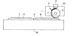
図1(a)〜(c)は、展色ロール4上で塗布面を形成し、ブランケット胴3上に転写する例を示す。シリコンシート(図を省略)を巻き付けたブランケット胴3は、ガラス定盤1、版定盤2を備えた固定フレーム19に沿って移動する可動フレーム20に取り付けられ、ブランケット胴3に上記展色ロール4が接して回転するもので、展色ロール4にはデスペンサー5、ブレード6を設けてある。
【0010】
この実施例1の動きは下記の順序となる。
1)デスペンサー5にて定められた量のインキ又は樹脂を展色ロール4上に滴下する。
2)ブレード6にて該インキをロール4表面に均一に展色する。
3)該展色インキ皮膜7をブランケット胴3上に転移する(図1(a)参照)。
4)ブランケット胴3上のインキ皮膜7に版定盤2上の凸版8を押圧し、凸部分インキ9をブランケット上のインキ皮膜から除去する(図1(b)参照)。
5)ブランケット胴3上の残りの(求める形状の)インキ皮膜10を定盤1上のガラス基板11に転写する(図1(c)参照)。
【0011】
(実施例2)
図2は、ブランケット胴3上で直接塗布面を形成する例を示す。この場合の動きは下記のとおりである。
1)デスペンサー5にて定められた量のインキ又は樹脂をブランケット胴3上に滴下する。
2)ブレード6にて該インキをブランケット胴3の表面に均一に塗布する。
3)ブランケット胴3上のインキ皮膜7に凸版8を押圧し、凸部分インキ9をブランケットのインキ皮膜から除去する(図1の(b)と共通)。
4)ブランケット上の残りの(求める形状の)インキ皮膜10を、ガラス基板11に転写する(図1の(c)と共通)。
【0012】
(実施例3)
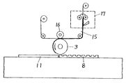
図3は、上記デスペンサー5の代わりに練りロール12を使用しブランケット胴3上で塗布面を形成する例を示す。
すなわち壺13から呼び出しロール14を経て練りロール12にインキを供給し、ブランケット胴3にインキを供給する。そしてブランケット胴3に取り付けてあるブレード6によって平坦な皮膜7が形成される。以後の動きは実施例1及び2と同じであり、同一符号は同一部分を示す。
【0013】
(実施例4)
図4は、実施例1の条件でカラ−フィルター作製を想定した3色機構成の例を示すもので、完全にインキが100%転写されるため、wet on wetで3色機構成が可能となる。図中2−R・2−G・2−Bは版定盤、3−R・3−G・3−Bはブランケット胴、5−R・5−G・5−Bはデスペンサー、6−R・6−G・6−Bはブレード、8−R・8−G・8−Bは凸版、18は凸版洗浄ユニットを示し、その他の符号は前述の実施例と同一である。
【0014】
(実施例5)
図5は、別手段としてコーティングユニット17を持った例(請求項3、6、11、15)を示すもので、ガラス定盤1、版定盤2が一体となって水平に移動する機構が構成され、両定盤と接して定点で回転するブランケット胴3、ブランケット胴3にはシリコンシートである展色シート15を挟み押圧するように圧着ロール16が取り付けてある。展色シート15は長尺となっており、供給手段であるコーティングユニット17を介している。
【0015】
その動きを説明すると、コーティングユニット17によって展色シート15にインキ皮膜が形成される。形成された皮膜はブランケット胴3の回転とともに展色シート15が移動しブランケット胴3の表面に転写される。以後の動きは実施例1〜3と同じである。
【0016】
上述した本発明の印刷機を使用するにあたっては、ブランケット胴3に撥インキ性処理されたブランケット(主にはシリコンブランケット)を用いることを前提とする。シリコンシート上に形成されたインキ皮膜7は凸版8やガラス等の基材を押圧すると接触した部分の全てを基材に転写させる性質がある。
【0017】
ところで通常インキ等樹脂が基材から基材へ転写されていく場合インキ等は両方に別れ、糸曳き現象が起きる。この糸曳き現象がインキ体質のムラを起こし平坦性、画素形状の低下や膜厚ムラの原因となり品質の低下を招いている。一般の印刷においては、ローラーで練る、版へのインキング、版からブランケットへの転写、ブランケットから基板への転写の全てのプロセスで糸曳き現象が生じており、これが印刷特有の品質とその品質的限界を作っている。
【0018】
これに対し本装置を使用した製法においては、一切この糸曳き現象を起こすプロセスを含んでいないためフォトリソ法における画像形成の品質と殆ど同じものができる。また実験した結果においても別表のように現在の印刷法よりフォトリソ法に近い品質のものが得られた。
【0019】
【表1】

因みに上記の表1における項目の「平坦性」とは、バラツキのレンジを示す値であって数値は小さい方が良く、「画素直線性」は、ウネリの幅レンジを示す値であってこれも数値は小さい方が良く、「インキ盛り量」とは、盛り量の融通性を示すもので数値は大きい方が良く、「寸法精度」は原理的要素に起因し、数値は小さい方が良い。しかして上記の結果から従来のカラ−フィルターに比べて本発明によるカラ−フィルターの優れていることが確認できた。
【0021】
【発明の効果】
以上のような本発明は以下のような特有の効果を奏する。
(1)インキ形状を安定させるため転写時に行うスリップと平坦化させるためのプレスを行わないため、マスク形状に忠実な画像形成ができることとなり、所謂デルタ型−CFも作製可能となる。
(2)画像エッジの直線性が良いため、現在フォトリソ法によって作製している遮光幕の形成法としても使用できる。また高精細CF(40〜50μ)にも対応できる。
(3)転写は一回で行うためタクト(色入れのみ)は現在の70秒が20秒となり、1/3以下となる。
(4)インキの糸曳き現象がないためCFの平坦性が一段上がり、LCD表示のざらつき感が減る。
(5)凸版のデザインを変えることにより、印刷によるオーバーコート法として使用できる。
(6)インキの転写は常に100%で行われるためwet on wetの印刷が可能となり、3色機構想(3色CF)が可能であり、また4色機構想(BM+3色CF)も可能となる。
(7)ブランケットのインキ離れが良いため(現在はないが)ガラス基板厚0.5mmにも対応できる。
(8)樹脂凸版を使うため小サイズ版の集合による付け合わせ印刷が可能となり将来の付け合わせによる基板の大型化においても、大型のマスク、露光機が不要となるため製造工程のコストアップを抑えることができる。また大型化に伴う寸法や位置の歪みにも版の位置補正で対応することができる。
(9)従来のフォトリソ法が、1)塗布、2)乾燥、3)露光、4)現像、5)乾燥と多くの工程を必要とするのに対し、本発明においては1)塗布・転写と胴の1回転、2)乾燥のみ、と極めて短い工程とタクトで行われるため製造コストを低くすることができる。
(10)更に別の用途でのインキ厚盛り印刷についてもシルク印刷に近い厚盛りを維持しつつオフセット印刷の精度と解像度が得られる印刷法を提供できる。
【図面の簡単な説明】
【図1】 展色ロール上で塗布面を形成しブランケット面に転写する実施例であり(a)は全体の側面図、(b)はブランケット胴から凸版がインキを取る説明図、(c)はブランケット胴からガラス基板へインキが転写される説明図である。
【図2】 ブランケット胴で直接塗布面を形成する実施例側面図である。
【図3】 デスペンサーの代わりに練りロールを使用しブランケット上で塗布面を形成する実施例側面図である。
【図4】 カラ−フィルター作製を想定した3色機構成の実施例側面図である。
【図5】 別手段としてコーティングユニットを持った実施例側面図である。
【符号の説明】
1 ガラス定盤
2 版定盤
3 ブランケット胴
4 展色ロール
6 ブレード
7 インキ皮膜
8 凸版
9 凸部分インキ
10 残りのインキ皮膜
11 ガラス基板
15 展色シート
16 圧着ロール
17 コーティングユニット
19 固定フレーム
20 可動フレーム[0001]
BACKGROUND OF THE INVENTION
The present invention relates to a printing machine and a printing method suitable for printing a functional resin such as a resist agent or a paste, or printing a product requiring high quality such as a color filter for liquid crystal.
[0002]
[Prior art]
Conventionally, when printing a functional resin, a silk printing machine is generally used. The silk printing method is widely used for the production of a printed circuit board and the patterning of a resist agent because it is relatively unquestionable such as the printability of a resin and thick printing is possible. In addition, an offset printing machine is used for printing the color filter for liquid crystal, and a flattening apparatus is used together if necessary.
[0003]
[Problems to be solved by the invention]
In silk printing, because sha is used, there is a limit to dimensional accuracy and resolution, so it is not used for high-definition products. On the other hand, offset printing causes ink stringing, so ink at a microscopic level is used. Unevenness in the film thickness occurred, and this was a big problem when manufacturing a filter.
[0004]
In view of such a conventional situation, the present invention intends to provide a printing machine and a printing method that can be thickened without degrading accuracy and have a flat surface.
[0005]
[Means for Solving the Problems]
That is, the present invention relates to a printing machine and a printing method having a blanket cylinder and printing ink or resin through the blanket, and means or functionality for forming an ink solid on a blanket cylinder that rotates by pressing a printing plate and a printing medium. The main purpose is to provide means for applying a resin.
[0006]
Furthermore, the present invention provides a means for supplying a solid ink or a means for supplying an applied functional resin to a blanket cylinder that rotates by pressing a printing plate and a printing medium in the printing machine and the printing method . The present invention provides a printing machine and a printing method that do not have the problems as in the prior art. Further, when carrying out the printing method of the present invention or when using the printing machine of the present invention, it is assumed that a blanket (mainly a silicon blanket) subjected to ink repellency treatment is used for the blanket cylinder. The blanket cylinder may be a blanket cylinder around which a silicon sheet is wound.
(1) The printing method of the present invention comprises an ink film or a resin film (hereinafter referred to as “ink film or the like” when referred to as either an ink film or a resin film) on the color developing roll. A film of ink or the like is formed, and a film of ink or the like is transferred onto a blanket cylinder (mainly a silicon blanket, the same applies hereinafter) cylinder that has been subjected to ink repellency treatment. The blanket cylinder is pressed against a printing plate on a platen plate and rotated to rotate ink or resin on the blanket cylinder (hereinafter referred to as “ink or the like” when referring to either ink or resin). The blanket cylinder is pressed against the printing medium on a surface plate and rotated to transfer the ink remaining on the blanket cylinder to the printing medium.
(2) Further, the printing method of the present invention supplies ink etc. to the kneading roll through the calling roll, and supplies the ink etc. from the kneading roll onto the blanket cylinder subjected to the ink repellency treatment. The blanket cylinder is pressed against a printing plate on a platen plate and rotated to remove ink on the blanket cylinder, and the blanket cylinder is pressed against a substrate to be printed on the platen and rotated. The printing method is characterized in that the ink remaining on the blanket cylinder is transferred to the printing medium.
(3) In the printing method of the present invention, a film such as ink is formed on the color developing sheet by a means for forming a film such as ink, and the film such as ink is formed on the blanket cylinder subjected to ink repellency treatment. Transfer to form a film such as ink on the blanket cylinder, the blanket cylinder is pressed against a printing plate on a platen plate and rotated to remove the ink on the blanket cylinder, the blanket cylinder, The printing method is characterized in that the ink or the like remaining on the blanket cylinder is transferred to the printing medium by pressing and rotating the printing medium on the surface plate.
(4) In the printing method of the present invention, a resin relief plate can be used as a printing plate. Further, as the resin relief plate, a garnish by a set of small-size printing plates can be used.
(5) Further, the printing machine of the present invention removes ink on the blanket cylinder by rotating the blanket cylinder subjected to the ink repellency treatment against the printing plate on the plate surface plate to rotate the blanket cylinder. In a printing machine for transferring ink remaining on the blanket cylinder to the printing medium by pressing and rotating the printing medium on the surface plate, a film such as ink is transferred onto the blanket cylinder A color developing roll and means for supplying the ink or the like to the color developing roll and forming a uniform film of the ink or the like on the surface of the color developing roll are provided.
(6) Further, the printing press of the present invention removes the ink on the blanket cylinder by rotating the blanket cylinder subjected to the ink repellency treatment against the printing plate on the plate surface plate to rotate the blanket cylinder. In a printing machine that presses and rotates the printing medium on the surface plate and transfers the ink remaining on the blanket cylinder to the printing medium, the ink or the like from the kneading roll via the calling roll on the blanket cylinder And a means for forming a film of ink or the like on the blanket cylinder.
(7) Further, the printing press of the present invention removes the ink on the blanket cylinder by rotating the ink-repellently treated blanket cylinder against the printing plate on the plate surface plate to rotate the blanket cylinder. In a printing machine that presses and rotates the printing medium on the surface plate and transfers the ink remaining on the blanket cylinder to the printing medium, a film such as ink is formed on the color developing sheet, and the ink A means for forming a film of ink or the like for transferring a film such as ink onto the blanket cylinder is provided.
(8) Further, the printing machine of the present invention forms a film such as ink on a blanket cylinder that has been subjected to ink repellency by means for forming a film such as ink, and the blanket cylinder is printed on a platen plate. The plate is pressed and rotated to remove ink and the like on the blanket cylinder, and the blanket cylinder is pressed against the substrate to be printed on the surface plate and rotated to remove the ink and the like remaining on the blanket cylinder. In a printing machine for transferring to a printing medium, a plurality of means for forming a film such as ink, the blanket cylinder, and the platen plate are provided so as to correspond to each other.
(9) The present invention also provides a printing press according to the above-described printing press according to the present invention, in which a printing plate cleaning unit for cleaning the printing plate is further provided on a frame common to the blanket cylinder.
(10) In the printing machine of the present invention, a resin relief plate can be used as a printing plate. Furthermore, as the resin relief plate, a garnish of a set of small size printing plates can be used.
[0007]
DETAILED DESCRIPTION OF THE INVENTION
In the printing method of the present invention, a solid ink or resin is formed on a blanket cylinder formed by winding a silicon sheet. Then, the resin relief plate is pressed against this, and the ink or resin of the convex portion is removed from the blanket surface, and the remaining ink or resin is transferred to the printing medium. The present invention further provides a printing machine that performs such a series of processes.
[0008]
【Example】
Next, the printing machine and printing method of the present invention will be described with reference to examples.
[0009]
(Example 1)
FIGS. 1A to 1C show an example in which a coating surface is formed on the
[0010]
The movement of the first embodiment is in the following order.
1) An amount of ink or resin determined by the
2) The ink is uniformly developed on the surface of the
3) The該展
4) presses the
5) The remaining (desired shape)
[0011]
(Example 2)
FIG. 2 shows an example in which a coating surface is directly formed on the
1) An amount of ink or resin determined by the
2) The ink is uniformly applied to the surface of the
3) The
4) The remaining (desired shape)
[0012]
(Example 3)
FIG. 3 shows an example in which a kneading
That is, the ink is supplied from the
[0013]
(Example 4)
FIG. 4 shows an example of a three-color machine configuration assuming color filter production under the conditions of Example 1, and since 100% of the ink is completely transferred, a three-color machine configuration is possible on a wet on wet basis. Become. In the figure, 2-R, 2-G, 2-B are platen plates, 3-R, 3-G, 3-B are blanket cylinders, 5-R, 5-G, 5-B are dispensers, 6- R, 6-G, and 6-B are blades, 8-R, 8-G, and 8-B are letterpress plates, and 18 is a letterplate washing unit.
[0014]
(Example 5)
FIG. 5 shows an example having a coating unit 17 as another means (
[0015]
Explaining the movement, an ink film is formed on the
[0016]
In using the printing press of the present invention described above, it is assumed that a blanket (mainly a silicon blanket) subjected to ink repellency treatment is used for the
[0017]
By the way, when a resin such as ink is transferred from a base material to a base material, the ink is divided into both, and a stringing phenomenon occurs. This stringing phenomenon causes unevenness in the ink constitution and causes a decrease in flatness, pixel shape and film thickness unevenness, resulting in a decrease in quality. In general printing, stringing occurs in all processes of kneading with a roller, inking to a plate, transferring from a plate to a blanket, and transferring from a blanket to a substrate. This is the quality and quality peculiar to printing. The limit is made.
[0018]
On the other hand, the manufacturing method using the present apparatus does not include any process that causes this stringing phenomenon, so that the image forming quality in the photolithography method can be almost the same. Also, as a result of the experiment, as shown in the attached table, a quality closer to the photolithography method than the current printing method was obtained.
[0019]
[Table 1]
Incidentally, the “flatness” of the item in Table 1 above is a value indicating the range of variation, and it is better that the numerical value is small, and the “pixel linearity” is a value indicating the width range of the ridge, which is also The smaller the numerical value, the better. The “ink filling amount” indicates the flexibility of the filling amount, and the larger numerical value is better. The “dimensional accuracy” is due to the principle element, and the smaller numerical value is better. From the above results, it was confirmed that the color filter according to the present invention was superior to the conventional color filter.
[0021]
【The invention's effect】
The present invention as described above has the following specific effects.
(1) In order to stabilize the ink shape, slipping during transfer and press for flattening are not performed, so that image formation faithful to the mask shape can be performed, and so-called delta-CFs can be produced.
(2) Since the linearity of the image edge is good, it can also be used as a method for forming a light-shielding curtain currently produced by photolithography. It can also handle high-definition CF (40-50μ).
(3) Since the transfer is performed once, the tact (coloring only) is 20 seconds from the current 70 seconds, which is 1/3 or less.
(4) Since there is no ink stringing phenomenon, the flatness of the CF is further increased and the roughness of the LCD display is reduced.
(5) By changing the design of the letterpress, it can be used as an overcoat method by printing.
(6) Since the ink transfer is always performed at 100%, it is possible to print wet on wet, 3 color mechanism concept (3 color CF) is possible, and 4 color mechanism concept (BM + 3 color CF) is also possible. Become.
(7) Since the ink removal of the blanket is good (not presently), it can cope with a glass substrate thickness of 0.5 mm.
(8) Since a resin relief printing plate is used, it is possible to perform garnish printing using a set of small sized plates, and even if the substrate is enlarged due to future garnishing, large masks and exposure machines are no longer required, thus suppressing an increase in manufacturing process costs. it can. In addition, it is possible to cope with dimensional and positional distortion accompanying the increase in size by correcting the position of the plate.
(9) The conventional photolithography method requires 1) coating, 2) drying, 3) exposure, 4) development, 5) drying and many steps, whereas in the present invention, 1) coating and transfer The manufacturing cost can be reduced because the process is performed in a very short process and tact, such as one rotation of the cylinder and 2) only drying.
(10) With respect to ink overlay printing in yet another application, it is possible to provide a printing method capable of obtaining the accuracy and resolution of offset printing while maintaining the overlay close to silk printing.
[Brief description of the drawings]
FIG. 1 is an embodiment in which an application surface is formed on a color developing roll and transferred to a blanket surface, (a) is an overall side view, (b) is an explanatory diagram in which a letterpress plate takes ink from a blanket cylinder, (c) These are explanatory drawings in which ink is transferred from a blanket cylinder to a glass substrate.
FIG. 2 is a side view of an embodiment in which a coating surface is directly formed by a blanket cylinder.
FIG. 3 is a side view of an embodiment in which a kneading roll is used instead of a dispenser to form an application surface on a blanket.
FIG. 4 is a side view of an embodiment of a three-color machine configuration assuming the production of a color filter.
FIG. 5 is a side view of an embodiment having a coating unit as another means.
[Explanation of symbols]
DESCRIPTION OF
Claims (19)
撥インキ性処理されたブランケット胴上に前記インキ皮膜を転移させて該ブランケット胴上に前記インキ皮膜を形成し、Transferring the ink film onto a blanket cylinder treated with ink repellency to form the ink film on the blanket cylinder;
前記ブランケット胴を、版定盤上の印刷版に押圧して回転させ該ブランケット胴上のインキを除去し、The blanket cylinder is pressed against a printing plate on a platen plate and rotated to remove ink on the blanket cylinder,
前記ブランケット胴を、定盤上の被印刷体に押圧して回転させ該ブランケット胴上に残っているインキを前記被印刷体に転写することを特徴とする印刷方法。A printing method, wherein the blanket cylinder is pressed against a printing medium on a surface plate and rotated to transfer the ink remaining on the blanket cylinder to the printing medium.
撥インキ性処理されたブランケット胴上に前記インキ皮膜を転移させて該ブランケット胴上にインキ皮膜を形成し、Transferring the ink film onto a blanket cylinder treated with ink repellency to form an ink film on the blanket cylinder;
前記ブランケット胴を、版定盤上の印刷版に押圧して回転させ該ブランケット胴上のインキを除去し、The blanket cylinder is pressed against a printing plate on a platen plate and rotated to remove ink on the blanket cylinder,
前記ブランケット胴を、定盤上の被印刷体に押圧して回転させ該ブランケット胴上に残っているインキを前記被印刷体に転写することを特徴とする印刷方法。A printing method, wherein the blanket cylinder is pressed against a substrate to be printed on a surface plate and rotated to transfer ink remaining on the blanket cylinder to the substrate to be printed.
シリコンブランケット胴上に前記樹脂皮膜を転移させて該シリコンブランケット胴上に該樹脂皮膜を形成し、Transferring the resin film onto a silicon blanket cylinder to form the resin film on the silicon blanket cylinder;
前記シリコンブランケット胴を、版定盤上の印刷版に押圧して回転させ該シリコンブランケット胴上の樹脂を除去し、The silicon blanket cylinder is pressed against a printing plate on a platen plate and rotated to remove the resin on the silicon blanket cylinder,
前記シリコンブランケット胴を、定盤上の被印刷体に押圧して回転させ該シリコンブランケット胴上に残っている樹脂を前記被印刷体に転写することを特徴とする印刷方法。A printing method, wherein the silicon blanket cylinder is pressed against a substrate to be printed on a surface plate and rotated to transfer the resin remaining on the silicon blanket cylinder to the substrate to be printed.
前記ブランケット胴を、版定盤上の印刷版に押圧して回転させブランケット胴上の樹脂を除去し、The blanket cylinder is pressed against the printing plate on the platen plate and rotated to remove the resin on the blanket cylinder,
前記ブランケット胴を、定盤上の被印刷体に押圧して回転させ該ブランケット胴上に残っている樹脂を前記被印刷体に転写することを特徴とする印刷方法。A printing method, wherein the blanket cylinder is pressed against a printing medium on a surface plate and rotated to transfer the resin remaining on the blanket cylinder to the printing medium.
シリコンブランケット胴上に前記樹脂皮膜を転移させて該シリコンブランケット胴上に前記樹脂皮膜を形成し、 Transferring the resin film onto a silicon blanket cylinder to form the resin film on the silicon blanket cylinder;
前記ブランケット胴を、版定盤上の印刷版に押圧して回転させ該ブランケット胴上の樹脂を除去し、The blanket cylinder is pressed against a printing plate on a platen plate and rotated to remove the resin on the blanket cylinder,
前記ブランケット胴を、定盤上の被印刷体に押圧して回転させ該ブランケット胴上に残っている樹脂を前記被印刷体に転写することを特徴とする印刷方法。A printing method, wherein the blanket cylinder is pressed against a printing medium on a surface plate and rotated to transfer the resin remaining on the blanket cylinder to the printing medium.
前記ブランケット胴上にインキ皮膜を転移する展色ロールと、A color developing roll for transferring an ink film onto the blanket cylinder;
前記展色ロールに前記インキを供給し、該展色ロール表面に均一な前記インキ皮膜を形成する手段とを設けていることを特徴とする印刷機。And a means for supplying the ink to the color developing roll and forming a uniform ink film on the surface of the color developing roll.
前記ブランケット胴上に呼び出しロールを経て練りロールからインキを供給して該ブランケット胴上にインキ皮膜を形成する手段を設けていることを特徴とする印刷機。A printing machine comprising means for forming an ink film on the blanket cylinder by supplying ink from a kneading roll via a calling roll onto the blanket cylinder.
展色シートにインキ皮膜を形成し、該インキ皮膜を前記ブランケット胴上に転移させるインキ皮膜を形成する手段を設けていることを特徴とする印刷機。A printing machine comprising means for forming an ink film on a color developing sheet and forming an ink film for transferring the ink film onto the blanket cylinder.
前記インキ皮膜を形成する手段と、前記ブランケット胴と、前記版定盤とが、夫々対応するように複数設けられていることを特徴とする印刷機。A printing machine comprising a plurality of means for forming the ink film, the blanket cylinder, and the platen so as to correspond to each other.
前記ブランケット胴上に樹脂皮膜を転移させる展色ロールと、A color developing roll for transferring a resin film onto the blanket cylinder;
前記樹脂を前記展色ロール上に供給して前記樹脂皮膜を形成する手段とを設けていることを特徴とする印刷機。Means for supplying the resin onto the color developing roll to form the resin film is provided.
前記シリコンブランケット胴上に呼び出しロールを経て練りロールから樹脂を供給し、該シリコンブランケット胴上に樹脂皮膜を形成する手段を設けていることを特徴とする印刷機。A printing machine comprising means for supplying a resin from a kneading roll via a calling roll onto the silicon blanket cylinder and forming a resin film on the silicon blanket cylinder.
展色シートに樹脂皮膜を形成し、該樹脂皮膜を前記ブランケット胴上に転移させる樹脂皮膜を形成する手段を設けていることを特徴とする印刷機。A printing machine comprising a means for forming a resin film on a color developing sheet and forming a resin film for transferring the resin film onto the blanket cylinder.
前記樹脂皮膜を形成する手段と、前記ブランケット胴と、前記版定盤とが、夫々対応するように複数設けられていることを特徴とする印刷機。A printing machine comprising a plurality of means for forming the resin film, the blanket cylinder, and the platen plate so as to correspond to each other.
Priority Applications (1)
| Application Number | Priority Date | Filing Date | Title |
|---|---|---|---|
| JP1344698A JP3730002B2 (en) | 1998-01-07 | 1998-01-07 | Printing machine and printing method |
Applications Claiming Priority (1)
| Application Number | Priority Date | Filing Date | Title |
|---|---|---|---|
| JP1344698A JP3730002B2 (en) | 1998-01-07 | 1998-01-07 | Printing machine and printing method |
Publications (2)
| Publication Number | Publication Date |
|---|---|
| JPH11198337A JPH11198337A (en) | 1999-07-27 |
| JP3730002B2 true JP3730002B2 (en) | 2005-12-21 |
Family
ID=11833371
Family Applications (1)
| Application Number | Title | Priority Date | Filing Date |
|---|---|---|---|
| JP1344698A Expired - Fee Related JP3730002B2 (en) | 1998-01-07 | 1998-01-07 | Printing machine and printing method |
Country Status (1)
| Country | Link |
|---|---|
| JP (1) | JP3730002B2 (en) |
Cited By (2)
| Publication number | Priority date | Publication date | Assignee | Title |
|---|---|---|---|---|
| US7516697B2 (en) | 2005-01-26 | 2009-04-14 | Mitsubishi Heavy Industries, Ltd | Single color press and method of operating same, and method of manufacturing liquid crystal color filter |
| US7972949B2 (en) | 2007-08-31 | 2011-07-05 | Nec Corporation | Electronic component and display device and a method of manufacturing the same |
Families Citing this family (26)
| Publication number | Priority date | Publication date | Assignee | Title |
|---|---|---|---|---|
| JP4108012B2 (en) * | 2003-07-08 | 2008-06-25 | 光村印刷株式会社 | Resin coated substrate manufacturing equipment |
| JP5095908B2 (en) * | 2004-01-28 | 2012-12-12 | 住友化学株式会社 | Printing apparatus and printing method |
| JP4715150B2 (en) * | 2004-09-30 | 2011-07-06 | 凸版印刷株式会社 | Pattern forming method and pattern forming apparatus |
| JP4710296B2 (en) * | 2004-09-30 | 2011-06-29 | 凸版印刷株式会社 | Pattern forming method and pattern forming apparatus |
| KR100628275B1 (en) | 2004-11-04 | 2006-09-27 | 엘지.필립스 엘시디 주식회사 | Printing Nozzle |
| KR101085141B1 (en) | 2004-12-17 | 2011-11-21 | 엘지디스플레이 주식회사 | Method of forming pattern having a step difference, method of making a thin film transistor and a Liquid Crystal Display Device using the same |
| KR101085140B1 (en) | 2004-12-23 | 2011-11-21 | 엘지디스플레이 주식회사 | Method of manufacturing a substrate for Liquid Crystal Display Device |
| JP4857584B2 (en) * | 2005-03-31 | 2012-01-18 | 凸版印刷株式会社 | Pattern forming method and pattern forming apparatus |
| JP4655724B2 (en) * | 2005-03-31 | 2011-03-23 | 凸版印刷株式会社 | Pattern forming apparatus and pattern forming method |
| JP4696644B2 (en) * | 2005-03-31 | 2011-06-08 | 凸版印刷株式会社 | Fine pattern forming method and forming apparatus used therefor |
| JP4815851B2 (en) * | 2005-04-15 | 2011-11-16 | 東洋インキScホールディングス株式会社 | Coloring composition |
| JP4580830B2 (en) | 2005-07-08 | 2010-11-17 | 株式会社日立製作所 | Image forming method and image forming apparatus using the same |
| TWI345804B (en) * | 2005-08-17 | 2011-07-21 | Lg Chemical Ltd | Patterning method using coatings containing ionic components |
| KR101147079B1 (en) * | 2005-08-25 | 2012-05-17 | 엘지디스플레이 주식회사 | method for manufacturing of printing plate |
| KR101157969B1 (en) * | 2005-09-12 | 2012-06-25 | 엘지디스플레이 주식회사 | Printing plate and Method of fabricating Liquid Crystal Display Device using the same |
| JP5048235B2 (en) * | 2005-11-04 | 2012-10-17 | 住友ゴム工業株式会社 | Printing device |
| KR101255295B1 (en) * | 2005-11-28 | 2013-04-15 | 엘지디스플레이 주식회사 | Printing Device System and Patterning method using the same |
| KR101255294B1 (en) | 2005-12-29 | 2013-04-23 | 엘지디스플레이 주식회사 | Printing Apparatus and Method of manufacturing Liquid Crystal Display Device using the same |
| JP2007237413A (en) * | 2006-03-06 | 2007-09-20 | Toppan Printing Co Ltd | Method for manufacturing printed matter |
| KR101232168B1 (en) * | 2006-06-30 | 2013-02-12 | 엘지디스플레이 주식회사 | Printing Device System, Patterning method using the same, and Method for manufacturing Liquid Crystal Display Device using the same |
| KR100800263B1 (en) * | 2006-08-24 | 2008-02-04 | 제일모직주식회사 | Electrode composition for offset print, method for preparing a electrode by the same and a plasma display panel using the same |
| JP2008129362A (en) * | 2006-11-21 | 2008-06-05 | Mitsubishi Heavy Ind Ltd | Printing device and method for controlling posture error in printing device |
| JP2011252072A (en) * | 2010-06-01 | 2011-12-15 | Sumitomo Rubber Ind Ltd | Ink |
| CN103314428B (en) * | 2011-04-01 | 2016-09-07 | Lg化学株式会社 | Printing equipment and printing process |
| KR101699466B1 (en) * | 2012-05-18 | 2017-01-24 | 준 사카모토 | Printer, printing device, and printing method |
| CN103481650B (en) * | 2013-08-23 | 2016-01-20 | 南京中电熊猫液晶显示科技有限公司 | A kind of alignment film printing machine |
-
1998
- 1998-01-07 JP JP1344698A patent/JP3730002B2/en not_active Expired - Fee Related
Cited By (2)
| Publication number | Priority date | Publication date | Assignee | Title |
|---|---|---|---|---|
| US7516697B2 (en) | 2005-01-26 | 2009-04-14 | Mitsubishi Heavy Industries, Ltd | Single color press and method of operating same, and method of manufacturing liquid crystal color filter |
| US7972949B2 (en) | 2007-08-31 | 2011-07-05 | Nec Corporation | Electronic component and display device and a method of manufacturing the same |
Also Published As
| Publication number | Publication date |
|---|---|
| JPH11198337A (en) | 1999-07-27 |
Similar Documents
| Publication | Publication Date | Title |
|---|---|---|
| JP3730002B2 (en) | Printing machine and printing method | |
| JP3689536B2 (en) | Image forming method | |
| JP4580830B2 (en) | Image forming method and image forming apparatus using the same | |
| JP2000289320A (en) | Imaging device | |
| US6098546A (en) | Method and device for security printing | |
| JP2008132743A (en) | Printer and printing process | |
| JP4364534B2 (en) | Image forming method | |
| JP5499822B2 (en) | Method for producing functional thin film | |
| JP4513334B2 (en) | Image forming apparatus and image forming method | |
| JP6115018B2 (en) | Thin film printing method and thin film printing apparatus | |
| JP4556391B2 (en) | Method for forming fine pattern | |
| JPH1191229A (en) | Method for forming pattern | |
| JPH07266532A (en) | Offset printing method, and manufacture of offset press used therefor, and manufacture of color filter using this method | |
| JP2005031191A (en) | Resin coated substrate and apparatus for manufacture the same | |
| JPH09113720A (en) | Formation of light shielding film of color filter and apparatus therefor | |
| JPH05169626A (en) | Offset printer | |
| JP2718583B2 (en) | Printing equipment | |
| TWI395670B (en) | Lithographic printing and embossing printing interchange method and printing device | |
| JP2007083645A (en) | Manufacturing method for blanket, and method and apparatus for forming pattern | |
| JP2006150849A (en) | Equipment and method for forming minute pattern | |
| JPH08244194A (en) | Letterpress printer and letterpress printing method | |
| JP2004009300A (en) | Flat-bed offset press | |
| JP2000141594A (en) | Equipment and method for offset printing | |
| JP2009214302A (en) | Letterpress printer | |
| JP2012206308A (en) | Printer, and method for manufacturing functional thin film using the same |
Legal Events
| Date | Code | Title | Description |
|---|---|---|---|
| A131 | Notification of reasons for refusal |
Free format text: JAPANESE INTERMEDIATE CODE: A131 Effective date: 20050104 |
|
| A131 | Notification of reasons for refusal |
Free format text: JAPANESE INTERMEDIATE CODE: A131 Effective date: 20050301 |
|
| A521 | Written amendment |
Free format text: JAPANESE INTERMEDIATE CODE: A523 Effective date: 20050502 |
|
| TRDD | Decision of grant or rejection written | ||
| A01 | Written decision to grant a patent or to grant a registration (utility model) |
Free format text: JAPANESE INTERMEDIATE CODE: A01 Effective date: 20050906 |
|
| A61 | First payment of annual fees (during grant procedure) |
Free format text: JAPANESE INTERMEDIATE CODE: A61 Effective date: 20051005 |
|
| R150 | Certificate of patent or registration of utility model |
Free format text: JAPANESE INTERMEDIATE CODE: R150 |
|
| FPAY | Renewal fee payment (event date is renewal date of database) |
Free format text: PAYMENT UNTIL: 20091014 Year of fee payment: 4 |
|
| FPAY | Renewal fee payment (event date is renewal date of database) |
Free format text: PAYMENT UNTIL: 20101014 Year of fee payment: 5 |
|
| S111 | Request for change of ownership or part of ownership |
Free format text: JAPANESE INTERMEDIATE CODE: R313115 |
|
| FPAY | Renewal fee payment (event date is renewal date of database) |
Free format text: PAYMENT UNTIL: 20101014 Year of fee payment: 5 |
|
| R350 | Written notification of registration of transfer |
Free format text: JAPANESE INTERMEDIATE CODE: R350 |
|
| FPAY | Renewal fee payment (event date is renewal date of database) |
Free format text: PAYMENT UNTIL: 20101014 Year of fee payment: 5 |
|
| FPAY | Renewal fee payment (event date is renewal date of database) |
Free format text: PAYMENT UNTIL: 20111014 Year of fee payment: 6 |
|
| FPAY | Renewal fee payment (event date is renewal date of database) |
Free format text: PAYMENT UNTIL: 20111014 Year of fee payment: 6 |
|
| FPAY | Renewal fee payment (event date is renewal date of database) |
Free format text: PAYMENT UNTIL: 20121014 Year of fee payment: 7 |
|
| FPAY | Renewal fee payment (event date is renewal date of database) |
Free format text: PAYMENT UNTIL: 20121014 Year of fee payment: 7 |
|
| FPAY | Renewal fee payment (event date is renewal date of database) |
Free format text: PAYMENT UNTIL: 20131014 Year of fee payment: 8 |
|
| R250 | Receipt of annual fees |
Free format text: JAPANESE INTERMEDIATE CODE: R250 |
|
| R250 | Receipt of annual fees |
Free format text: JAPANESE INTERMEDIATE CODE: R250 |
|
| R250 | Receipt of annual fees |
Free format text: JAPANESE INTERMEDIATE CODE: R250 |
|
| R250 | Receipt of annual fees |
Free format text: JAPANESE INTERMEDIATE CODE: R250 |
|
| LAPS | Cancellation because of no payment of annual fees |