JP3706571B2 - Multi-stage pressure condenser - Google Patents
Multi-stage pressure condenser Download PDFInfo
- Publication number
- JP3706571B2 JP3706571B2 JP2001347056A JP2001347056A JP3706571B2 JP 3706571 B2 JP3706571 B2 JP 3706571B2 JP 2001347056 A JP2001347056 A JP 2001347056A JP 2001347056 A JP2001347056 A JP 2001347056A JP 3706571 B2 JP3706571 B2 JP 3706571B2
- Authority
- JP
- Japan
- Prior art keywords
- pressure
- condensate
- chamber
- low
- condenser
- Prior art date
- Legal status (The legal status is an assumption and is not a legal conclusion. Google has not performed a legal analysis and makes no representation as to the accuracy of the status listed.)
- Expired - Fee Related
Links
Images


Classifications
-
- F—MECHANICAL ENGINEERING; LIGHTING; HEATING; WEAPONS; BLASTING
- F28—HEAT EXCHANGE IN GENERAL
- F28B—STEAM OR VAPOUR CONDENSERS
- F28B1/00—Condensers in which the steam or vapour is separate from the cooling medium by walls, e.g. surface condenser
- F28B1/02—Condensers in which the steam or vapour is separate from the cooling medium by walls, e.g. surface condenser using water or other liquid as the cooling medium
-
- F—MECHANICAL ENGINEERING; LIGHTING; HEATING; WEAPONS; BLASTING
- F28—HEAT EXCHANGE IN GENERAL
- F28B—STEAM OR VAPOUR CONDENSERS
- F28B9/00—Auxiliary systems, arrangements, or devices
- F28B9/08—Auxiliary systems, arrangements, or devices for collecting and removing condensate
-
- F—MECHANICAL ENGINEERING; LIGHTING; HEATING; WEAPONS; BLASTING
- F28—HEAT EXCHANGE IN GENERAL
- F28C—HEAT-EXCHANGE APPARATUS, NOT PROVIDED FOR IN ANOTHER SUBCLASS, IN WHICH THE HEAT-EXCHANGE MEDIA COME INTO DIRECT CONTACT WITHOUT CHEMICAL INTERACTION
- F28C3/00—Other direct-contact heat-exchange apparatus
- F28C3/06—Other direct-contact heat-exchange apparatus the heat-exchange media being a liquid and a gas or vapour
-
- Y—GENERAL TAGGING OF NEW TECHNOLOGICAL DEVELOPMENTS; GENERAL TAGGING OF CROSS-SECTIONAL TECHNOLOGIES SPANNING OVER SEVERAL SECTIONS OF THE IPC; TECHNICAL SUBJECTS COVERED BY FORMER USPC CROSS-REFERENCE ART COLLECTIONS [XRACs] AND DIGESTS
- Y10—TECHNICAL SUBJECTS COVERED BY FORMER USPC
- Y10S—TECHNICAL SUBJECTS COVERED BY FORMER USPC CROSS-REFERENCE ART COLLECTIONS [XRACs] AND DIGESTS
- Y10S261/00—Gas and liquid contact apparatus
- Y10S261/10—Steam heaters and condensers
Description
【0001】
【発明の属する技術分野】
本発明は、圧力が異なる複数の室を有し、複数の室に溜められた復水を合流させて圧送する多段圧復水器に関する。
【0002】
【従来の技術】
蒸気タービン設備においては、仕事を終えた蒸気がタービン排気室から復水器に導入され、復水器で凝縮されて復水とされる。復水器で凝縮された復水は、給水加熱器を介して加熱された後、ボイラ側に供給されて蒸気とされ蒸気タービンの駆動源として用いられる。
【0003】
復水器で凝縮された復水が給水加熱器に送られる場合、復水の温度が高いほどプラントの効率面で有利となる。このため従来から、圧力が異なる複数の室からなる多段圧復水器が用いられ、低圧側復水を高圧室の蒸気により加熱してボイラへ供給する復水の高温化が図られている。具体的には、低圧側復水を高圧蒸気の中で液滴や液膜として自由落下させ、接触伝熱で加熱している。また、多段圧復水器を用いることで、冷却水温度と飽和蒸気温度との温度差を広げて伝熱面積を減らすことができる。
【0004】
【発明が解決しようとする課題】
従来の多段圧復水器にあっては、低圧側復水を高圧蒸気の中で液滴や液膜として自由落下させて接触伝熱で加熱しているので、液滴や液膜を高圧蒸気の中に存在させる時間を長くすることで、効率的に加熱が行われる。しかし、低圧側復水の液滴や液膜を高圧蒸気の中に存在させる時間を長くするためには、落下高さを高くする必要があり、コンパクト化を阻害するものとなっていた。コンパクト化のために落下高さを最小限に抑えると、加熱が不十分となってプラントの効率面で有利にならなくなってしまう。
【0005】
本発明は上記状況に鑑みてなされたもので、コンパクト化とプラントの効率向上を両立させることができる多段圧復水器を提供することを目的とする。
【0007】
【課題を解決するための手段】
上記目的を達成するための本発明の構成は、圧力が異なる複数の室を有し、複数の室に溜められた復水を合流させて圧送する多段圧復水器において、低圧側の室である低圧室の下部に圧力隔壁によって仕切られ低圧側復水が導入されて溜められる再熱室を設け、高圧側の室である高圧室内の高圧蒸気を再熱室に導入する高圧蒸気導入手段を設けると共に、低圧復水を再熱室に導入する低圧復水導入手段を設け、再熱室の復水に循環流を生じさせて表面乱流熱伝達を起こす循環流発生手段を備え復水に対する高圧側蒸気による熱伝達を促進することを特徴とする。
【0008】
そして、循環流発生手段は、圧力隔壁に低圧側復水が滴下する滴下孔を設けると共に再熱室内に滴下孔から滴下した低圧側復水を溜めてオーバーフローさせる受け部材を設け、受け部材からオーバーフローした低圧側復水により再熱室の復水に循環流を生じさせることを特徴とする。また、再熱室に溜められる復水を仕切り壁により複数部位に仕切ることで混合を抑制させることを特徴とする。
【0012】
【発明の実施の形態】
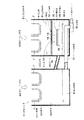
図1には本発明の一実施形態例に係る多段圧復水器の概略構成を表す断面、図2には冷却水の流通状況を説明する平面状況を示してある。
【0013】
蒸気タービンは高圧側蒸気タービンと低圧側蒸気タービンとで構成され、図1に示すように、高圧側蒸気タービンの排気蒸気の出口側には高圧段復水器1の高圧胴2が連結され、低圧側蒸気タービンの排気蒸気の出口側には低圧段復水器3の低圧胴4が連結されている。高圧段復水器1の高圧胴2により高圧側の室である高圧室5が形成され、低圧段復水器3の低圧胴4により低圧側の室である低圧室6が形成されている。
【0014】
高圧室5及び低圧室6にはそれぞれ冷却水管群7が設けられている。図2に示すように、低圧室6の冷却水管群7に冷却水として、例えば、海水が導入管7aから導入され、低圧室6の冷却水管群7から高圧室5の冷却水管群7に連結管7bにより送られ、排出管7cから排出される。高圧室5及び低圧室6には蒸気タービンで仕事を終えた排気蒸気が送られ、排気蒸気は冷却水管群7の冷却水により凝縮され、高圧側復水8となって高圧室5に溜められると共に、低圧側復水9となって低圧室6に溜められる。
【0015】
低圧室6の下部における低圧胴4には再熱室11が設けられ、低圧室6と再熱室11は圧力隔壁12によって仕切られている。高圧室5と再熱室11は蒸気ダクト10でつながれ、蒸気ダクト10から高圧室5内の高圧側蒸気が再熱室11に送られる。圧力隔壁12には多孔板13が設けられ、多孔板13には滴下孔としての孔14が多数形成されている。多孔板13の下部における再熱室11には受け部材としてのトレイ15が設けられ、トレイ15には孔14からの低圧側復水9が滴下(散水)するようになっている。トレイ15に捕集された復水はオーバーフローして落下して再熱室11に復水20として溜められる。トレイ15をオーバーフローして落下する流下復水19により再熱室11に溜められた復水20に循環流が生じ、復水20の表面で表面乱流熱伝達が起こるようになっている。
【0016】
再熱室11の下部には合流部16が設けられ、バイパス手段としてのバイパス連結管17が高圧室5から合流部16につながっている。バイパス連結管17は断熱構造の材質のものが好ましく、バイパス連結管17は温度低下を最小限にして高圧側復水8を合流部16に導いて復水20と合流させる。合流部16で合流された復水20及び高圧側復水8は復水ポンプ側に送られて給水加熱器等を介してボイラ側に送られる。高圧側復水8は再熱室11の復水20をバイパスして合流されるようになっているので、復水20は高温に保たれた高圧側復水8と混合されて高温の復水を復水ポンプ側に送ることができる。
【0017】
上記構成の多段圧復水器では、高圧室5及び低圧室6には蒸気タービンで仕事を終えた排気蒸気が送られ、排気蒸気は冷却水管群7により凝縮され、高圧側復水8となって高圧室5に溜められると共に、低圧側復水9となって低圧室6に溜められる。低圧室6に溜められた低圧側復水9は多孔板13の孔14から再熱室11のトレイ15に滴下して溜められる。再熱室11には蒸気ダクト10から高圧室5内の高圧側蒸気が送られているため、トレイ15に滴下する低圧側復水9は高圧側蒸気中を滴下して接触伝熱で加熱される。トレイ15をオーバーフローして落下する流下復水19は再熱室11に溜められた復水20に循環流を生じさせ、送られた高圧側蒸気と広い面積で接触して表面乱流熱伝達を起こす。
【0018】
これにより、低圧側復水9は高圧側蒸気中を滴下する際の表面乱流熱伝達と、オーバーフローして落下する流下復水19により生じた循環流による表面乱流熱伝達とで、良好な熱伝達が行われて効率的に昇温される。このため、液滴を高圧蒸気の中に存在させる時間を長くすることなく効率的に加熱が行われるようになり、コンパクト化のために落下空間を最小限に抑えた状態で十分に低圧側復水9の加熱が行える。従って、コンパクト化と動力プラントの効率向上を両立させることを可能にした多段圧復水器とすることが可能になる。
【0019】
また、バイパス連結管17により、高圧側復水8が再熱室11の復水20をバイパスして合流されるようになっているので、高圧側復水8は高温に保たれた状態で復水20に混合され、高い温度の復水を復水ポンプ側に送ることができる。再熱室11に溜められた復水20の水面温度が高くなることが防止され、水面で高圧側蒸気と接触する際の表面乱流熱伝達における伝熱量を最大にすることができる。
【0020】
図3に基づいて多段圧復水器の一例を説明する。図3にはその多段圧復水器の概略構成を表す断面を示してある。尚、図1に示した部材と同一部材には同一符号を付して重複する説明は省略してある。
【0021】
図3に示した多段圧復水器は、高圧側復水8の復水20への混合が図1に示した多段圧復水器と異なる構成となっている。即ち、図3に示すように、バイパス連結管17に代えて、高圧室5と再熱室11とをつなぐ連結管21を設けた構成となっている。復水20は連結管21により高圧室5に送られ、高圧室5で高圧側復水8に混合される。
【0022】
このため、配管系統が簡素になり、低圧段復水器3回りの省スペース化が図れると共に合流部16等の設計の自由度が増す。
【0023】
図4に基づいて多段圧復水器の一例を説明する。図4にはその多段圧復水器の概略構成を表す断面を示してある。尚、図3に示した部材と同一部材には同一符号を付して重複する説明は省略してある。
【0024】
図4に示した多段圧復水器は、低圧室6に溜められた低圧側復水9の再熱室11への導入の構成が図2に示した多段圧復水器と異なる構成となっている。即ち、圧力隔壁12には多孔板13に代えて孔板22が設けられ、孔板22には低圧側復水9が流下する流通孔23が設けられている。低圧側復水9は流通孔23から流下して流下復水24となり、流下復水24は再熱室11に溜められた復水20に直接落下して循環流を生じさせ、送られた高圧側蒸気が復水20の表面で広い面積で接触して表面乱流熱伝達を起こす。流通孔23の数や径は、低圧室6や再熱室11の圧力等により適宜設定される。
【0025】
このため、再熱室11に溜められた復水20に循環流を生じさせるための部材(トレイ15)が不要になり、再熱室11を小さくして低圧段復水器3のコンパクト化が図れる。尚、図1に示した多段圧復水器に孔板22を備えた圧力隔壁12を用いる構成にすることも可能である。
【0026】
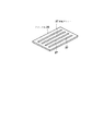
図5、図6に基づいて多段圧復水器の一例を説明する。図5にはその多段圧復水器の概略構成を表す断面、図6にはスリット板の斜視を示してある。尚、図3に示した部材と同一部材には同一符号を付して重複する説明は省略してある。
【0027】
図5に示した多段圧復水器は、低圧室6に溜められた低圧側復水9の再熱室11への導入の構成が図3に示した多段圧復水器と異なる構成となっている。即ち、圧力隔壁12には多孔板13に代えてスリット板26が設けられ、スリット板26には、図6に示すように、低圧側復水9が膜状に流下する流通スリット27が設けられている。低圧側復水9は流通スリット27から膜状に流下して流下復水28となり、流下復水28は再熱室11に溜められた復水20に帯状に直接落下して循環流を生じさせ、送られた高圧側蒸気が復水20の表面で広い面積で接触して表面乱流熱伝達を起こす。
【0028】
このため、再熱室11に溜められた復水20に循環流を生じさせるための部材(トレイ15)が不要になり、再熱室11を小さくして低圧段復水器3のコンパクト化が図れる。尚、図1に示した多段圧復水器にスリット板26を備えた圧力隔壁12を用いる構成にすることも可能である。
【0029】
図7に基づいて多段圧復水器の一例を説明する。図7にはその多段圧復水器の概略構成を表す断面を示してある。尚、図3に示した部材と同一部材には同一符号を付して重複する説明は省略してある。
【0030】
図7に示した多段圧復水器は、再熱室11に溜められた復水20に循環流を生じさせる構成が図2に示した多段圧復水器と異なる構成となっている。即ち、再熱室11に溜められた復水20の内部には攪拌手段としてモータ31で回転される攪拌スクリュウ32が配置されている。低圧側復水9は多孔板13の孔14から滴下してそのまま再熱室11に溜められて復水20となる。攪拌スクリュウ32の回転により復水20が直接攪拌されて循環流を生じさせ、送られた高圧側蒸気が復水20の表面で広い面積で接触して表面乱流熱伝達を起こす。
【0031】
このため、再熱室11に溜められた復水20に循環流を生じさせるための部材(トレイ15)が不要になり、再熱室11を小さくして低圧段復水器3のコンパクト化が図れる。尚、図1乃至図6に示した多段圧復水器に攪拌手段を追加する構成にすることも可能である。
【0032】
図8に基づいて多段圧復水器の一例を説明する。図8にはその多段圧復水器の概略構成を表す断面を示してある。尚、図3に示した部材と同一部材には同一符号を付して重複する説明は省略してある。
【0033】
図8に示した多段圧復水器は、低圧室6に溜められた低圧側復水9の再熱室11への導入の構成が図2に示した多段圧復水器と異なる構成となっている。即ち、圧力隔壁12には多孔板13に代えて再熱室11側に延びるパイプ35が設けられている。低圧側復水9はパイプ35に充満されて流下して流下復水36となり、流下復水36は流速が高められて再熱室11に溜められた復水20に直接落下して循環流を生じさせ、送られた高圧側蒸気が復水20の表面で広い面積で接触して表面乱流熱伝達を起こす。
【0034】
上述した一実施形態例及び一例における多段圧復水器において、再熱室11の復水20を仕切り壁により複数部位に仕切り、各部位の復水20の混合を抑制することも可能である。復水20の混合を抑制することにより、循環流が狭い範囲で生じることになり、循環流の形成が促進されてより効果的に表面乱流熱伝達が行えるようになる。
【0035】
図9に基づいて多段圧復水器の一例を説明する。図9にはその多段圧復水器の概略構成を表す断面を示してある。尚、図3に示した部材と同一部材には同一符号を付して重複する説明は省略してある。
【0036】
図9に示した多段圧復水器は、低圧室6に溜められた低圧側復水9の再熱室11への導入の構成、及び、再熱室11に溜められた復水20に循環流を生じさせる構成が図3に示した多段圧復水器と異なる構成となっている。即ち、圧力隔壁12には低圧側復水9が流通する流通部としての流通孔38(もしくはスリット)が設けられている。また、流通孔38の下部における再熱室11には流通孔38からの流下復水40が溜められる復水溜り39が設けられ、復水溜り39は再熱室11に溜められた復水20の水面より高い開口部41を有している。
【0037】
復水溜り39に溜められた流下復水40は内部で循環流が生じ、送られた高圧側蒸気が溜められた流下復水40の表面で広い面積で接触して表面乱流熱伝達を起こす。また、復水溜り39をオーバーフローして流下復水42が落下し、流下復水42は再熱室11に溜められた復水20に循環流を生じさせ、送られた高圧側蒸気と広い面積で接触して表面乱流熱伝達を起こす。
【0038】
尚、図1に示した多段圧復水器に流通孔38を備えた圧力隔壁12を用い復水溜り39を設けた構成にすることも可能である。また、復水溜り39の内部に更に復水溜りを設置して流下復水42を多段回にオーバーフローさせるように構成することも可能である。
【0039】
上述した各実施形態例の構成は、それぞれプラントの規模等に応じて単独同士または複数同士を適宜組み合わせて適用することが可能である。
【0040】
図10に基づいて多段圧復水器の一例を説明する。図10にはその多段圧復水器の概略構成を表す断面を示してある。
【0041】
高圧側蒸気タービンの排気蒸気の出口側には高圧段復水器51の高圧胴52が連結され、低圧側蒸気タービンの排気蒸気の出口側には低圧段復水器53の低圧胴54が連結されている。高圧段復水器51の高圧胴52により高圧側の室である高圧室55が形成され、低圧段復水器53の低圧胴54により低圧側の室である低圧室56が形成されている。高圧室55の下部には隔壁61を介して第2高圧室62が形成されている。
【0042】
高圧室55及び低圧室56にはそれぞれ冷却水管群57が設けられている。それぞれの冷却水管群57には、図2に示した状態で、海水等の冷却水が送られるようになっている。高圧室55及び低圧室56には蒸気タービンで仕事を終えた排気蒸気が送られ、排気蒸気は冷却管群57の冷却水により凝縮され、高圧側復水58及び低圧側復水59となる。
【0043】
高圧室55内の冷却水管群57の下部には高圧側復水58を受けて第2高圧室62に導入する受け部材63が設けられ、高圧側復水58は受け部材63から第2高圧室62に送られて溜められるようになっている。また、低圧側復水59は低圧室56の下部に溜められる。
【0044】
低圧室56の下部から高圧室55の内部に延びる導入部材64が設けられ、導入部材64の先端部の出口部71は高圧室55の内部に配置されている。低圧室56に溜められた低圧側復水59が導入部材64を通して出口部71に送られ、出口部71の上面からオーバーフローして落下し高圧室55の下部に復水66として溜められる。導入部材64の出口部71の上面は低圧室56の下部よりも低い位置に配置され、低圧側復水59は高低差によって導入部材64の上面開口からオーバーフローして高圧室55に流下される。導入部材64の出口部71をオーバーフローして落下する流下復水65は高圧側蒸気により加熱されながら落下し、高圧室55の下部に溜められた復水66に循環流を生じさせ、復水66の表面で表面乱流熱伝達が起こるようになっている。
【0045】
高圧室55の下部に溜められた復水66と第2高圧室62に溜められた高圧側復水58は、図示しない合流部で混合されて復水ポンプ側に送られる。
【0046】
上記構成の多段圧復水器では、高圧室55及び低圧室56には蒸気タービンで仕事を終えた排気蒸気が送られ、排気蒸気は冷却管群57により凝縮される。高圧室55で凝縮された高圧側復水58は受け部材63から第2高圧室62に送られて溜められる。低圧室56で凝縮された低圧側復水59は低圧室56の下部に溜められ、導入部材64を通って高圧室55側に送られる。導入部材64を通って送られた低圧側復水59は出口部71からオーバーフローして流下復水65となって落下し高圧室55の下部に復水66として溜められる。流下復水65は高圧室55で高圧側蒸気中を落下するため、接触伝熱で加熱される。導入部材64の出口部上面をオーバーフローして落下する流下復水65は高圧室55に溜められた復水66に循環流を生じさせ、高圧室55内の高圧側蒸気と広い面積で接触して表面乱流熱伝達を起こす。
【0047】
これにより、低圧側復水59は流下復水65となって高圧室56内で高圧側蒸気中をオーバーフローする際の接触伝熱と、オーバーフローして落下する流下復水65により生じた復水66の循環流による表面乱流熱伝達とで、良好な熱伝達が行われて効率的に昇温される。このため、効率的に加熱が行われるようになり、コンパクト化のために落下空間を最小限に抑えた状態で十分に低圧側復水59の加熱が行える。従って、コンパクト化と動力プラントの効率向上を両立させることを可能にした多段圧復水器とすることが可能になる。
【0048】
尚、導入部材64の出口部71の上面を低圧室56の下部よりも低い位置に配置して、高低差によって低圧側復水59を導入部材64の上面開口からオーバーフローさせるようにしているが、低圧側復水59を圧送する圧送手段を設けることも可能である。圧送手段を設けることで、高圧段復水器51や低圧段復水器53の設置の自由度が増し、設置スペースの制約が少なくなる。
【0050】
【発明の効果】
本発明の多段圧復水器は、圧力が異なる複数の室を有し、複数の室に溜められた復水を合流させて圧送する多段圧復水器において、低圧側の室である低圧室の下部に圧力隔壁によって仕切られ低圧側復水が導入されて溜められる再熱室を設け、高圧側の室である高圧室内の高圧蒸気を再熱室に導入する高圧蒸気導入手段を設けると共に、低圧復水を再熱室に導入する低圧復水導入手段を設け、再熱室の復水に循環流を生じさせて表面乱流熱伝達を起こす循環流発生手段を備え復水に対する高圧側蒸気による熱伝達を促進するようにしたので、高圧側蒸気中の接触伝熱と循環流による表面乱流熱伝達とで低圧側復水は再熱室で良好な熱伝達が行われて効率的に昇温される。この結果、液滴を高圧蒸気の中に存在させる時間を長くする必要がなくなり、効率的に加熱が行われるようになり、コンパクト化のために落下空間を最小限に抑えた状態で十分に低圧側復水の加熱が行え、コンパクト化と動力プラントの効率向上を両立させることを可能にした多段圧復水器とすることが可能になる。
【0051】
また、本発明の多段圧復水器は、圧力が異なる複数の室を有し、複数の室に溜められた復水を合流させて圧送する多段圧復水器において、低圧側の室である低圧室の下部に圧力隔壁で仕切られ低圧側復水が導入されて溜められる再熱室を設け、高圧側の室である高圧室内の高圧側蒸気を再熱室に導入する高圧蒸気導入手段を設け、圧力隔壁に低圧側復水が滴下する滴下孔を設けると共に再熱室内に滴下孔から滴下した低圧側復水を溜めてオーバーフローさせる受け部材を設け、受け部材からオーバーフローした低圧側復水により再熱室の復水に循環流を生じさせる一方、再熱室の復水をバイパスさせた高圧側復水を再熱室の復水と合流させて復水の温度を高めるバイパス手段を設けたので、高圧側蒸気中の接触伝熱と循環流による表面乱流熱伝達とで低圧側復水は再熱室で良好な熱伝達が行われて効率的に昇温されると共に、液滴を高圧蒸気の中に存在させる時間を長くする必要がなくなり、効率的に加熱が行われるようになる。この結果、コンパクト化のために落下空間を最小限に抑えた状態で十分に低圧側復水の加熱が行え、しかも、高圧側復水の温度を低下させることなく低圧側復水と合流させることができ、交換熱量の高い復水を復水ポンプ側に送ることができ、コンパクト化と動力プラントの効率向上を両立させることを可能にした多段圧復水器とすることが可能になる。
【図面の簡単な説明】
【図1】本発明の第1実施形態例に係る多段圧復水器の概略構成を表す断面図。
【図2】冷却水の流通状況を説明する平面図。
【図3】 多段圧復水器の概略構成を表す断面図。
【図4】 多段圧復水器の概略構成を表す断面図。
【図5】 多段圧復水器の概略構成を表す断面図。
【図6】スリット板の斜視図。
【図7】 多段圧復水器の概略構成を表す断面図。
【図8】 多段圧復水器の概略構成を表す断面図。
【図9】 多段圧復水器の概略構成を表す断面図。
【図10】 多段圧復水器の概略構成を表す断面図。
【符号の説明】
1,51 高圧段復水器
2,52 高圧胴
3,53 低圧段復水器
4,54 低圧胴
5,55 高圧室
6,56 低圧室
7,57 冷却水管群
8,58 高圧側復水
9,59 低圧側復水
10 蒸気ダクト
11 再熱室
12 圧力隔壁
13 多孔板
14 孔
15 トレイ
16 合流部
17 バイパス連結管
19,24,28,36,40,65 流下復水
20,66 復水
21 連結管
22 孔板
23,38 流通孔
26 スリット板
27 流通スリット
31 モータ
32 攪拌スクリュウ
35 パイプ
39 復水溜り
41 開口部
61 隔壁
62 第2高圧室
63 受け部材
64 導入部材
71 出口部[0001]
BACKGROUND OF THE INVENTION
The present invention relates to a multi-stage pressure condenser that has a plurality of chambers having different pressures, and that condensates the condensate accumulated in the plurality of chambers and pumps them.
[0002]
[Prior art]
In the steam turbine facility, the finished steam is introduced into the condenser from the turbine exhaust chamber and condensed in the condenser to be condensed water. The condensed water condensed in the condenser is heated through a feed water heater and then supplied to the boiler side to be converted into steam and used as a drive source for the steam turbine.
[0003]
When the condensate condensed in the condenser is sent to the feed water heater, the higher the condensate temperature, the more advantageous the plant efficiency. For this reason, conventionally, a multi-stage pressure condenser comprising a plurality of chambers having different pressures has been used to increase the temperature of the condensed water supplied to the boiler by heating the low-pressure side condensate with steam in the high-pressure chamber. Specifically, the low-pressure side condensate is freely dropped as a droplet or liquid film in high-pressure steam and heated by contact heat transfer. Moreover, by using a multistage pressure condenser, the temperature difference between the cooling water temperature and the saturated steam temperature can be widened to reduce the heat transfer area.
[0004]
[Problems to be solved by the invention]
In a conventional multistage pressure condenser, the low-pressure side condensate is freely dropped as a droplet or liquid film in high-pressure steam and heated by contact heat transfer. Heating is performed efficiently by lengthening the time in which it exists. However, in order to increase the time during which the low-pressure condensate droplets and liquid film exist in the high-pressure steam, it is necessary to increase the drop height, which hinders downsizing. If the drop height is kept to a minimum for compactness, heating becomes insufficient and it becomes less advantageous in terms of plant efficiency.
[0005]
The present invention has been made in view of the above situation, and an object of the present invention is to provide a multistage pressure condenser that can achieve both compactness and improved plant efficiency.
[0007]
[Means for Solving the Problems]
In order to achieve the above object, the configuration of the present invention includes a plurality of chambers having different pressures, and a multistage pressure condenser that condenses and condenses the condensate stored in the plurality of chambers. A high pressure steam introducing means for introducing a high pressure steam in a high pressure chamber, which is a high pressure side chamber, is provided at a lower portion of a low pressure chamber and partitioned by a pressure partition to store the low pressure side condensate. A low-pressure condensate introduction means for introducing the low-pressure condensate into the reheat chamber is provided, and a circulation flow generating means for generating a circulatory flow in the condensate in the reheat chamber to cause surface turbulent heat transfer is provided. It is characterized by promoting heat transfer by high-pressure side steam.
[0008]
The circulating flow generating means is provided with a dropping hole for dropping the low-pressure side condensate in the pressure partition and a receiving member for collecting and overflowing the low-pressure side condensate dropped from the dropping hole in the reheating chamber, and overflowing from the receiving member. A circulating flow is generated in the condensate in the reheating chamber by the low-pressure side condensate. Moreover, mixing is suppressed by dividing the condensate stored in the reheating chamber into a plurality of parts by partition walls.
[0012]
DETAILED DESCRIPTION OF THE INVENTION
FIG. 1 is a cross-sectional view showing a schematic configuration of a multistage pressure condenser according to an embodiment of the present invention , and FIG. 2 shows a plan view for explaining the flow of cooling water.
[0013]
The steam turbine is composed of a high-pressure side steam turbine and a low-pressure side steam turbine. As shown in FIG. 1, a high-pressure body 2 of a high-pressure condenser 1 is connected to the outlet side of the exhaust steam of the high-pressure side steam turbine. A low-pressure cylinder 4 of a low-pressure stage condenser 3 is connected to an exhaust steam outlet side of the steam turbine. A high pressure chamber 5, which is a high pressure side chamber, is formed by the high pressure drum 2 of the high pressure stage condenser 1, and a
[0014]
A cooling
[0015]
A
[0016]
A junction 16 is provided in the lower part of the
[0017]
In the multistage pressure condenser having the above-described configuration, the exhaust steam that has finished work in the steam turbine is sent to the high pressure chamber 5 and the
[0018]
As a result, the low-pressure side condensate 9 has good surface turbulent heat transfer when dripping in the high-pressure side steam and surface turbulent heat transfer due to the circulating flow generated by the falling
[0019]
Further, since the high pressure side condensate 8 bypasses the condensate 20 of the reheating
[0020]
An example of a multistage pressure condenser will be described with reference to FIG. The FIG. 3 shows a cross-section illustrating a schematic configuration of a multistage pressure condenser. In addition, the same code | symbol is attached | subjected to the same member as the member shown in FIG. 1, and the overlapping description is abbreviate | omitted.
[0021]
The multistage pressure condenser shown in FIG. 3 has a different configuration from the multistage pressure condenser shown in FIG. 1 in mixing the high pressure side condensate 8 with the condensate 20. That is, as shown in FIG. 3, a connecting pipe 21 that connects the high-pressure chamber 5 and the reheating
[0022]
For this reason, the piping system is simplified, the space around the low-pressure stage condenser 3 can be saved, and the degree of freedom in designing the junction 16 and the like is increased.
[0023]
An example of a multistage pressure condenser will be described with reference to FIG. The Figure 4 is shown a cross-sectional view illustrating a schematic configuration of a multistage pressure condenser. In addition, the same code | symbol is attached | subjected to the same member as the member shown in FIG. 3, and the overlapping description is abbreviate | omitted.
[0024]
The multistage pressure condenser shown in FIG. 4 is different from the multistage pressure condenser shown in FIG. 2 in the configuration of introduction of the low pressure side condensate 9 stored in the
[0025]
For this reason, a member (tray 15) for generating a circulating flow in the condensate 20 stored in the
[0026]
An example of a multistage pressure condenser will be described with reference to FIGS. The Figure 5 cross section showing a schematic configuration of a multistage pressure condenser, in FIG. 6 are shown perspective of the slit plate. In addition, the same code | symbol is attached | subjected to the same member as the member shown in FIG. 3, and the overlapping description is abbreviate | omitted.
[0027]
The multistage pressure condenser shown in FIG. 5 is different from the multistage pressure condenser shown in FIG. 3 in the configuration of introducing the low pressure side condensate 9 stored in the
[0028]
For this reason, a member (tray 15) for generating a circulating flow in the condensate 20 stored in the
[0029]
An example of a multistage pressure condenser will be described with reference to FIG. The Figure 7 is shown a cross-sectional view illustrating a schematic configuration of a multistage pressure condenser. In addition, the same code | symbol is attached | subjected to the same member as the member shown in FIG. 3, and the overlapping description is abbreviate | omitted.
[0030]
The multi-stage pressure condenser shown in FIG. 7 is different from the multi-stage pressure condenser shown in FIG. 2 in that the circulation flow is generated in the condensate 20 stored in the reheating
[0031]
For this reason, a member (tray 15) for generating a circulating flow in the condensate 20 stored in the
[0032]
An example of a multistage pressure condenser will be described with reference to FIG. The Figure 8 there is shown a cross-sectional view illustrating a schematic configuration of a multistage pressure condenser. In addition, the same code | symbol is attached | subjected to the same member as the member shown in FIG. 3, and the overlapping description is abbreviate | omitted.
[0033]
The multi-stage pressure condenser shown in FIG. 8 is different from the multi-stage pressure condenser shown in FIG. 2 in the configuration for introducing the low-pressure side condensate 9 stored in the low-
[0034]
In the above-described embodiment and the multi-stage pressure condenser in the example, it is possible to partition the condensate 20 of the reheating
[0035]
An example of a multistage pressure condenser will be described with reference to FIG. The Figure 9 there is shown a cross-sectional view illustrating a schematic configuration of a multistage pressure condenser. In addition, the same code | symbol is attached | subjected to the same member as the member shown in FIG. 3, and the overlapping description is abbreviate | omitted.
[0036]
The multistage pressure condenser shown in FIG. 9 is configured to introduce the low-pressure side condensate 9 stored in the low-
[0037]
The downstream condensate 40 stored in the condensate reservoir 39 generates a circulating flow inside, and contacts the surface of the downstream condensate 40 where the high-pressure side steam is stored in a wide area to cause surface turbulent heat transfer. . Moreover, the condensate reservoir 39 overflows and the falling
[0038]
The multistage pressure condenser shown in FIG. 1 may have a condensate reservoir 39 using the
[0039]
The configuration of each embodiment described above can be applied singly or in combination with each other according to the scale of the plant.
[0040]
An example of a multistage pressure condenser will be described with reference to FIG. The Figure 10 there is shown a cross-sectional view illustrating a schematic configuration of a multistage pressure condenser.
[0041]
A high-pressure drum 52 of the high-pressure stage condenser 51 is connected to the outlet side of the exhaust steam of the high-pressure side steam turbine, and a low-pressure cylinder 54 of the low-pressure stage condenser 53 is connected to the outlet side of the exhaust steam of the low-pressure side steam turbine. A
[0042]
A cooling
[0043]
A receiving
[0044]
An introduction member 64 extending from the lower portion of the low pressure chamber 56 to the inside of the
[0045]
The
[0046]
In the multi-stage pressure condenser having the above-described configuration, exhaust steam that has finished work in the steam turbine is sent to the
[0047]
As a result, the low-pressure side condensate 59 becomes a flowing-down condensate 65, contact heat transfer when overflowing the high-pressure side steam in the high-pressure chamber 56, and
[0048]
The upper surface of the outlet portion 71 of the introduction member 64 is arranged at a position lower than the lower portion of the low pressure chamber 56 so that the low pressure side condensate 59 overflows from the upper surface opening of the introduction member 64 due to the height difference. It is also possible to provide a pumping means for pumping the low-pressure side condensate 59. By providing the pumping means, the degree of freedom of installation of the high-pressure stage condenser 51 and the low-pressure stage condenser 53 is increased, and the installation space restriction is reduced.
[0050]
【The invention's effect】
The multi-stage pressure condenser of the present invention has a plurality of chambers having different pressures, and a low-pressure chamber that is a low-pressure side chamber in the multi-stage pressure condenser that condenses and feeds the condensate accumulated in the plurality of chambers. A reheating chamber partitioned by a pressure partition and provided by storing the low pressure side condensate is provided at a lower portion of the upper portion, and a high pressure steam introducing means for introducing the high pressure steam in the high pressure chamber which is a high pressure side chamber into the reheating chamber is provided. Low pressure condensate introduction means for introducing low pressure condensate into the reheat chamber is provided, and circulation flow generating means for generating a circulatory flow in the condensate in the reheat chamber to cause surface turbulent heat transfer is provided. The heat transfer due to the high pressure side steam and the surface turbulent heat transfer due to the circulation flow are effective for efficient heat transfer in the reheating chamber. The temperature is raised. As a result, it is not necessary to lengthen the time for which the droplets are present in the high-pressure steam, heating is performed efficiently, and the pressure is sufficiently low with the fall space minimized for compactness. The side condensate can be heated, and a multi-stage pressure condenser capable of achieving both compactness and improved power plant efficiency can be achieved.
[0051]
Further, the multistage pressure condenser of the present invention has a plurality of chambers having different pressures, and is a low pressure side chamber in the multistage pressure condenser that condenses and feeds the condensate accumulated in the plurality of chambers. A high-pressure steam introducing means for introducing a high-pressure side steam in the high-pressure chamber, which is a high-pressure side chamber, is provided at the lower part of the low-pressure chamber and partitioned by a pressure partition and stored by introducing low-pressure side condensate. Provided with a dropping hole for dropping the low-pressure side condensate in the pressure partition and a receiving member for collecting and overflowing the low-pressure side condensate dropped from the dropping hole in the reheating chamber. A bypass means is provided to increase the temperature of the condensate by causing the condensate in the reheat chamber to circulate, and the high-pressure side condensate that bypasses the condensate in the reheat chamber to merge with the condensate in the reheat chamber. So, contact heat transfer in high pressure side steam and surface turbulent heat due to circulation flow Therefore, the low-pressure side condensate is heated efficiently by good heat transfer in the reheating chamber, and it is not necessary to lengthen the time for the droplets to exist in the high-pressure steam. Heating is performed. As a result, for compactness, the low-pressure condensate can be heated sufficiently with the fall space kept to a minimum, and combined with the low-pressure condensate without lowering the temperature of the high-pressure condensate. Therefore, the condensate with a high exchange heat amount can be sent to the condensate pump side, and it becomes possible to provide a multi-stage pressure condenser that can achieve both compactness and improved power plant efficiency.
[Brief description of the drawings]
FIG. 1 is a cross-sectional view illustrating a schematic configuration of a multistage pressure condenser according to a first embodiment of the present invention.
FIG. 2 is a plan view illustrating a circulation state of cooling water.
FIG. 3 is a cross-sectional view illustrating a schematic configuration of a multistage pressure condenser .
FIG. 4 is a cross-sectional view illustrating a schematic configuration of a multistage pressure condenser .
FIG. 5 is a cross-sectional view illustrating a schematic configuration of a multi-stage pressure condenser .
FIG. 6 is a perspective view of a slit plate.
FIG. 7 is a cross-sectional view illustrating a schematic configuration of a multistage pressure condenser .
FIG. 8 is a cross-sectional view showing a schematic configuration of a multistage pressure condenser .
FIG. 9 is a cross-sectional view showing a schematic configuration of a multistage pressure condenser .
FIG. 10 is a cross-sectional view showing a schematic configuration of a multistage pressure condenser .
[Explanation of symbols]
1,51 High pressure stage condenser 2,52 High pressure cylinder 3,53 Low pressure stage condenser 4,54
Claims (3)
Priority Applications (6)
| Application Number | Priority Date | Filing Date | Title |
|---|---|---|---|
| JP2001347056A JP3706571B2 (en) | 2001-11-13 | 2001-11-13 | Multi-stage pressure condenser |
| EP02024454A EP1310756A3 (en) | 2001-11-13 | 2002-10-29 | Multistage pressure condenser |
| CA002410836A CA2410836C (en) | 2001-11-13 | 2002-11-01 | Multistage pressure condenser |
| US10/288,471 US6814345B2 (en) | 2001-11-13 | 2002-11-06 | Multistage pressure condenser |
| CNB021504903A CN1314935C (en) | 2001-11-13 | 2002-11-13 | Multi-stage pressure condenser |
| US10/948,326 US7111832B2 (en) | 2001-11-13 | 2004-09-24 | Multistage pressure condenser |
Applications Claiming Priority (1)
| Application Number | Priority Date | Filing Date | Title |
|---|---|---|---|
| JP2001347056A JP3706571B2 (en) | 2001-11-13 | 2001-11-13 | Multi-stage pressure condenser |
Publications (2)
| Publication Number | Publication Date |
|---|---|
| JP2003148876A JP2003148876A (en) | 2003-05-21 |
| JP3706571B2 true JP3706571B2 (en) | 2005-10-12 |
Family
ID=19160119
Family Applications (1)
| Application Number | Title | Priority Date | Filing Date |
|---|---|---|---|
| JP2001347056A Expired - Fee Related JP3706571B2 (en) | 2001-11-13 | 2001-11-13 | Multi-stage pressure condenser |
Country Status (5)
| Country | Link |
|---|---|
| US (2) | US6814345B2 (en) |
| EP (1) | EP1310756A3 (en) |
| JP (1) | JP3706571B2 (en) |
| CN (1) | CN1314935C (en) |
| CA (1) | CA2410836C (en) |
Cited By (7)
| Publication number | Priority date | Publication date | Assignee | Title |
|---|---|---|---|---|
| JP2009052867A (en) * | 2007-08-29 | 2009-03-12 | Toshiba Corp | Multistage pressure condenser |
| WO2009075300A1 (en) | 2007-12-10 | 2009-06-18 | Kabushiki Kaisha Toshiba | Steam condenser |
| JP2011007394A (en) * | 2009-06-24 | 2011-01-13 | Toshiba Corp | Multistage pressure condenser |
| WO2012117597A1 (en) | 2011-02-28 | 2012-09-07 | 三菱重工業株式会社 | Multistage pressure condenser and steam turbine plant equipped with same |
| US8360402B2 (en) | 2007-10-16 | 2013-01-29 | Kabushiki Kaisha Toshiba | Multi-pressure condenser and condensate reheating method |
| WO2013080950A1 (en) | 2011-11-28 | 2013-06-06 | 三菱重工業株式会社 | Multistage pressure condenser and steam turbine plant provided with same |
| WO2014126154A1 (en) | 2013-02-13 | 2014-08-21 | 三菱日立パワーシステムズ株式会社 | Condenser, multistage pressure condenser provided therewith, and reheating module used in condenser |
Families Citing this family (8)
| Publication number | Priority date | Publication date | Assignee | Title |
|---|---|---|---|---|
| JP3706571B2 (en) * | 2001-11-13 | 2005-10-12 | 三菱重工業株式会社 | Multi-stage pressure condenser |
| JP2008256279A (en) * | 2007-04-05 | 2008-10-23 | Toshiba Corp | Condensing facility |
| US8286430B2 (en) * | 2009-05-28 | 2012-10-16 | General Electric Company | Steam turbine two flow low pressure configuration |
| JP5716233B2 (en) * | 2010-12-27 | 2015-05-13 | 三菱日立パワーシステムズ株式会社 | Multi-stage pressure condenser |
| JP5885990B2 (en) * | 2011-10-13 | 2016-03-16 | 三菱重工業株式会社 | Multistage condenser and turbine plant equipped with the same |
| JP6101527B2 (en) * | 2013-03-22 | 2017-03-22 | 三菱重工業株式会社 | Steam turbine plant |
| CN104154769B (en) * | 2014-05-15 | 2016-04-06 | 东南大学常州研究院 | Possess automatically except the plate-type condenser of liquid function |
| CN104154770B (en) * | 2014-05-15 | 2016-01-27 | 东南大学常州研究院 | The horizontal scraping fluid condenser of shell based on siphon principle |
Family Cites Families (14)
| Publication number | Priority date | Publication date | Assignee | Title |
|---|---|---|---|---|
| US2643052A (en) * | 1949-03-23 | 1953-06-23 | Guardite Corp | Three-stage condenser |
| US2956784A (en) * | 1958-07-02 | 1960-10-18 | Maryland Shipbuilding And Dryd | Apparatus for condensing and deaerating |
| GB1193956A (en) * | 1966-08-24 | 1970-06-03 | English Electric Co Ltd | Steam Turbine Plant |
| US3698476A (en) * | 1970-12-31 | 1972-10-17 | Worthington Corp | Counter flow-dual pressure vent section deaerating surface condenser |
| JPS5223009B2 (en) * | 1972-03-10 | 1977-06-21 | ||
| US3834133A (en) * | 1972-12-22 | 1974-09-10 | Foster Wheeler Corp | Direct contact condenser having an air removal system |
| FR2426878A1 (en) * | 1978-05-25 | 1979-12-21 | Alsthom Atlantique | Two=part condenser for steam turbine - uses condensate from one part to assist in condensing steam in other part |
| JPS567985A (en) * | 1979-06-30 | 1981-01-27 | Toshiba Corp | Jet condenser |
| US4288133A (en) * | 1980-03-17 | 1981-09-08 | The Maytag Company | Appliance control housing and console construction |
| DE3460673D1 (en) * | 1983-06-09 | 1986-10-16 | Bbc Brown Boveri & Cie | Multi-stage steam generator condenser with reheating arrangements for the suppression of condensate under cooling |
| US5083606A (en) * | 1990-08-09 | 1992-01-28 | Texas Utilities Electric Company | Structure and method for on-line inspection of condenser tubes |
| JPH11173768A (en) * | 1997-12-10 | 1999-07-02 | Mitsubishi Heavy Ind Ltd | Multistage pressure condenser |
| US6484503B1 (en) * | 2000-01-12 | 2002-11-26 | Arie Raz | Compression and condensation of turbine exhaust steam |
| JP3706571B2 (en) * | 2001-11-13 | 2005-10-12 | 三菱重工業株式会社 | Multi-stage pressure condenser |
-
2001
- 2001-11-13 JP JP2001347056A patent/JP3706571B2/en not_active Expired - Fee Related
-
2002
- 2002-10-29 EP EP02024454A patent/EP1310756A3/en not_active Withdrawn
- 2002-11-01 CA CA002410836A patent/CA2410836C/en not_active Expired - Fee Related
- 2002-11-06 US US10/288,471 patent/US6814345B2/en not_active Expired - Lifetime
- 2002-11-13 CN CNB021504903A patent/CN1314935C/en not_active Expired - Fee Related
-
2004
- 2004-09-24 US US10/948,326 patent/US7111832B2/en not_active Expired - Lifetime
Cited By (16)
| Publication number | Priority date | Publication date | Assignee | Title |
|---|---|---|---|---|
| JP2009052867A (en) * | 2007-08-29 | 2009-03-12 | Toshiba Corp | Multistage pressure condenser |
| US8360402B2 (en) | 2007-10-16 | 2013-01-29 | Kabushiki Kaisha Toshiba | Multi-pressure condenser and condensate reheating method |
| WO2009075300A1 (en) | 2007-12-10 | 2009-06-18 | Kabushiki Kaisha Toshiba | Steam condenser |
| US8505886B2 (en) | 2009-06-24 | 2013-08-13 | Kabushiki Kaisha Toshiba | Multistage pressure condenser |
| JP2011007394A (en) * | 2009-06-24 | 2011-01-13 | Toshiba Corp | Multistage pressure condenser |
| EP2282151A2 (en) | 2009-06-24 | 2011-02-09 | Kabushiki Kaisha Toshiba | Multistage pressure condenser |
| WO2012117597A1 (en) | 2011-02-28 | 2012-09-07 | 三菱重工業株式会社 | Multistage pressure condenser and steam turbine plant equipped with same |
| JP2012180956A (en) * | 2011-02-28 | 2012-09-20 | Mitsubishi Heavy Ind Ltd | Multistage pressure condenser, and steam turbine plant equipped with the same |
| US9188393B2 (en) | 2011-02-28 | 2015-11-17 | Mitsubishi Hitachi Power Systems, Ltd. | Multistage pressure condenser and steam turbine plant equipped with the same |
| US20130167536A1 (en) * | 2011-11-28 | 2013-07-04 | Mitsubishi Heavy Industries, Ltd. | Multistage pressure condenser and steam turbine plant having the same |
| KR20140042902A (en) | 2011-11-28 | 2014-04-07 | 미츠비시 쥬고교 가부시키가이샤 | Multistage pressure condenser and steam turbine plant provided with same |
| WO2013080950A1 (en) | 2011-11-28 | 2013-06-06 | 三菱重工業株式会社 | Multistage pressure condenser and steam turbine plant provided with same |
| US9488416B2 (en) | 2011-11-28 | 2016-11-08 | Mitsubishi Hitachi Power Systems, Ltd. | Multistage pressure condenser and steam turbine plant having the same |
| WO2014126154A1 (en) | 2013-02-13 | 2014-08-21 | 三菱日立パワーシステムズ株式会社 | Condenser, multistage pressure condenser provided therewith, and reheating module used in condenser |
| KR20150092293A (en) | 2013-02-13 | 2015-08-12 | 미츠비시 히타치 파워 시스템즈 가부시키가이샤 | Condenser, multistage pressure condenser provided therewith, and reheating module used in condenser |
| US9638469B2 (en) | 2013-02-13 | 2017-05-02 | Mitsubishi Hitachi Power Systems, Ltd. | Condenser, multistage pressure condenser provided therewith, and reheating module used in condenser |
Also Published As
| Publication number | Publication date |
|---|---|
| EP1310756A3 (en) | 2005-03-30 |
| CN1419038A (en) | 2003-05-21 |
| CN1314935C (en) | 2007-05-09 |
| JP2003148876A (en) | 2003-05-21 |
| CA2410836A1 (en) | 2003-05-13 |
| US20050034455A1 (en) | 2005-02-17 |
| CA2410836C (en) | 2007-01-02 |
| EP1310756A2 (en) | 2003-05-14 |
| US6814345B2 (en) | 2004-11-09 |
| US20030090010A1 (en) | 2003-05-15 |
| US7111832B2 (en) | 2006-09-26 |
Similar Documents
| Publication | Publication Date | Title |
|---|---|---|
| JP3706571B2 (en) | Multi-stage pressure condenser | |
| JP6701372B2 (en) | Heat exchanger | |
| RU2317500C2 (en) | Combined capacitor with air cooling | |
| EP2841864B1 (en) | Heat exchanger | |
| CN103774402A (en) | Laundry machine | |
| US2512271A (en) | Water-cooling tower | |
| US6233941B1 (en) | Condensation system | |
| EP2682701B1 (en) | Multistage pressure condenser and steam turbine plant equipped with same | |
| JP2009292318A (en) | Heat exchanger | |
| US8881690B2 (en) | Steam generator | |
| JP5210605B2 (en) | Condenser and cooling device | |
| US4372126A (en) | Closed cycle system for generating usable energy from waste heat sources | |
| JPS5851194B2 (en) | Dry cooling power plant system | |
| EP2218999A1 (en) | Steam condenser | |
| JP6354030B2 (en) | Water treatment equipment | |
| WO2004092663A1 (en) | Evaporator and heat exchanger with external loop, as well as heat pump system and air conditioning system comprising said evaporator or heat exchanger | |
| JPS62162868A (en) | Evaporator | |
| US1085624A (en) | Absorber for refrigerating apparatus. | |
| EP0842688A1 (en) | Integral deaerator for a condenser | |
| CN219551244U (en) | Steam cooling condenser and heat exchange device thereof | |
| KR100344992B1 (en) | Fluid path pattern of heat exchanger | |
| CN101469859A (en) | Waste heat boiler and steam drum thereof | |
| JP2000130962A (en) | Spray condenser | |
| JP6341170B2 (en) | Heat pump steam generator | |
| US407838A (en) | Apparatus for utilizing waste heat from steam-engines and similar apparatus |
Legal Events
| Date | Code | Title | Description |
|---|---|---|---|
| A977 | Report on retrieval |
Free format text: JAPANESE INTERMEDIATE CODE: A971007 Effective date: 20050317 |
|
| A131 | Notification of reasons for refusal |
Free format text: JAPANESE INTERMEDIATE CODE: A131 Effective date: 20050405 |
|
| A521 | Written amendment |
Free format text: JAPANESE INTERMEDIATE CODE: A523 Effective date: 20050530 |
|
| A131 | Notification of reasons for refusal |
Free format text: JAPANESE INTERMEDIATE CODE: A131 Effective date: 20050614 |
|
| A521 | Written amendment |
Free format text: JAPANESE INTERMEDIATE CODE: A523 Effective date: 20050622 |
|
| TRDD | Decision of grant or rejection written | ||
| A01 | Written decision to grant a patent or to grant a registration (utility model) |
Free format text: JAPANESE INTERMEDIATE CODE: A01 Effective date: 20050712 |
|
| A61 | First payment of annual fees (during grant procedure) |
Free format text: JAPANESE INTERMEDIATE CODE: A61 Effective date: 20050729 |
|
| FPAY | Renewal fee payment (event date is renewal date of database) |
Free format text: PAYMENT UNTIL: 20080805 Year of fee payment: 3 |
|
| FPAY | Renewal fee payment (event date is renewal date of database) |
Free format text: PAYMENT UNTIL: 20090805 Year of fee payment: 4 |
|
| FPAY | Renewal fee payment (event date is renewal date of database) |
Free format text: PAYMENT UNTIL: 20090805 Year of fee payment: 4 |
|
| FPAY | Renewal fee payment (event date is renewal date of database) |
Free format text: PAYMENT UNTIL: 20100805 Year of fee payment: 5 |
|
| FPAY | Renewal fee payment (event date is renewal date of database) |
Free format text: PAYMENT UNTIL: 20100805 Year of fee payment: 5 |
|
| FPAY | Renewal fee payment (event date is renewal date of database) |
Free format text: PAYMENT UNTIL: 20110805 Year of fee payment: 6 |
|
| FPAY | Renewal fee payment (event date is renewal date of database) |
Free format text: PAYMENT UNTIL: 20110805 Year of fee payment: 6 |
|
| FPAY | Renewal fee payment (event date is renewal date of database) |
Free format text: PAYMENT UNTIL: 20120805 Year of fee payment: 7 |
|
| FPAY | Renewal fee payment (event date is renewal date of database) |
Free format text: PAYMENT UNTIL: 20130805 Year of fee payment: 8 |
|
| S111 | Request for change of ownership or part of ownership |
Free format text: JAPANESE INTERMEDIATE CODE: R313111 |
|
| R350 | Written notification of registration of transfer |
Free format text: JAPANESE INTERMEDIATE CODE: R350 |
|
| R250 | Receipt of annual fees |
Free format text: JAPANESE INTERMEDIATE CODE: R250 |
|
| LAPS | Cancellation because of no payment of annual fees |