JP3677924B2 - Display method and control method of video game apparatus - Google Patents
Display method and control method of video game apparatus Download PDFInfo
- Publication number
- JP3677924B2 JP3677924B2 JP03241897A JP3241897A JP3677924B2 JP 3677924 B2 JP3677924 B2 JP 3677924B2 JP 03241897 A JP03241897 A JP 03241897A JP 3241897 A JP3241897 A JP 3241897A JP 3677924 B2 JP3677924 B2 JP 3677924B2
- Authority
- JP
- Japan
- Prior art keywords
- monitor screen
- display mode
- specific image
- display
- axis
- Prior art date
- Legal status (The legal status is an assumption and is not a legal conclusion. Google has not performed a legal analysis and makes no representation as to the accuracy of the status listed.)
- Expired - Fee Related
Links
Images


Classifications
-
- A—HUMAN NECESSITIES
- A63—SPORTS; GAMES; AMUSEMENTS
- A63F—CARD, BOARD, OR ROULETTE GAMES; INDOOR GAMES USING SMALL MOVING PLAYING BODIES; VIDEO GAMES; GAMES NOT OTHERWISE PROVIDED FOR
- A63F7/00—Indoor games using small moving playing bodies, e.g. balls, discs or blocks
- A63F7/06—Games simulating outdoor ball games, e.g. hockey or football
- A63F7/0664—Electric
-
- A—HUMAN NECESSITIES
- A63—SPORTS; GAMES; AMUSEMENTS
- A63F—CARD, BOARD, OR ROULETTE GAMES; INDOOR GAMES USING SMALL MOVING PLAYING BODIES; VIDEO GAMES; GAMES NOT OTHERWISE PROVIDED FOR
- A63F13/00—Video games, i.e. games using an electronically generated display having two or more dimensions
- A63F13/55—Controlling game characters or game objects based on the game progress
- A63F13/57—Simulating properties, behaviour or motion of objects in the game world, e.g. computing tyre load in a car race game
-
- A63F13/10—
-
- A—HUMAN NECESSITIES
- A63—SPORTS; GAMES; AMUSEMENTS
- A63F—CARD, BOARD, OR ROULETTE GAMES; INDOOR GAMES USING SMALL MOVING PLAYING BODIES; VIDEO GAMES; GAMES NOT OTHERWISE PROVIDED FOR
- A63F13/00—Video games, i.e. games using an electronically generated display having two or more dimensions
- A63F13/20—Input arrangements for video game devices
- A63F13/24—Constructional details thereof, e.g. game controllers with detachable joystick handles
- A63F13/245—Constructional details thereof, e.g. game controllers with detachable joystick handles specially adapted to a particular type of game, e.g. steering wheels
-
- A—HUMAN NECESSITIES
- A63—SPORTS; GAMES; AMUSEMENTS
- A63F—CARD, BOARD, OR ROULETTE GAMES; INDOOR GAMES USING SMALL MOVING PLAYING BODIES; VIDEO GAMES; GAMES NOT OTHERWISE PROVIDED FOR
- A63F13/00—Video games, i.e. games using an electronically generated display having two or more dimensions
- A63F13/45—Controlling the progress of the video game
-
- A—HUMAN NECESSITIES
- A63—SPORTS; GAMES; AMUSEMENTS
- A63F—CARD, BOARD, OR ROULETTE GAMES; INDOOR GAMES USING SMALL MOVING PLAYING BODIES; VIDEO GAMES; GAMES NOT OTHERWISE PROVIDED FOR
- A63F13/00—Video games, i.e. games using an electronically generated display having two or more dimensions
- A63F13/80—Special adaptations for executing a specific game genre or game mode
- A63F13/812—Ball games, e.g. soccer or baseball
-
- A—HUMAN NECESSITIES
- A63—SPORTS; GAMES; AMUSEMENTS
- A63F—CARD, BOARD, OR ROULETTE GAMES; INDOOR GAMES USING SMALL MOVING PLAYING BODIES; VIDEO GAMES; GAMES NOT OTHERWISE PROVIDED FOR
- A63F13/00—Video games, i.e. games using an electronically generated display having two or more dimensions
- A63F13/80—Special adaptations for executing a specific game genre or game mode
- A63F13/843—Special adaptations for executing a specific game genre or game mode involving concurrently two or more players on the same game device, e.g. requiring the use of a plurality of controllers or of a specific view of game data for each player
-
- A—HUMAN NECESSITIES
- A63—SPORTS; GAMES; AMUSEMENTS
- A63F—CARD, BOARD, OR ROULETTE GAMES; INDOOR GAMES USING SMALL MOVING PLAYING BODIES; VIDEO GAMES; GAMES NOT OTHERWISE PROVIDED FOR
- A63F2300/00—Features of games using an electronically generated display having two or more dimensions, e.g. on a television screen, showing representations related to the game
- A63F2300/10—Features of games using an electronically generated display having two or more dimensions, e.g. on a television screen, showing representations related to the game characterized by input arrangements for converting player-generated signals into game device control signals
- A63F2300/1062—Features of games using an electronically generated display having two or more dimensions, e.g. on a television screen, showing representations related to the game characterized by input arrangements for converting player-generated signals into game device control signals being specially adapted to a type of game, e.g. steering wheel
-
- A—HUMAN NECESSITIES
- A63—SPORTS; GAMES; AMUSEMENTS
- A63F—CARD, BOARD, OR ROULETTE GAMES; INDOOR GAMES USING SMALL MOVING PLAYING BODIES; VIDEO GAMES; GAMES NOT OTHERWISE PROVIDED FOR
- A63F2300/00—Features of games using an electronically generated display having two or more dimensions, e.g. on a television screen, showing representations related to the game
- A63F2300/60—Methods for processing data by generating or executing the game program
- A63F2300/64—Methods for processing data by generating or executing the game program for computing dynamical parameters of game objects, e.g. motion determination or computation of frictional forces for a virtual car
-
- A—HUMAN NECESSITIES
- A63—SPORTS; GAMES; AMUSEMENTS
- A63F—CARD, BOARD, OR ROULETTE GAMES; INDOOR GAMES USING SMALL MOVING PLAYING BODIES; VIDEO GAMES; GAMES NOT OTHERWISE PROVIDED FOR
- A63F2300/00—Features of games using an electronically generated display having two or more dimensions, e.g. on a television screen, showing representations related to the game
- A63F2300/60—Methods for processing data by generating or executing the game program
- A63F2300/66—Methods for processing data by generating or executing the game program for rendering three dimensional images
-
- A—HUMAN NECESSITIES
- A63—SPORTS; GAMES; AMUSEMENTS
- A63F—CARD, BOARD, OR ROULETTE GAMES; INDOOR GAMES USING SMALL MOVING PLAYING BODIES; VIDEO GAMES; GAMES NOT OTHERWISE PROVIDED FOR
- A63F2300/00—Features of games using an electronically generated display having two or more dimensions, e.g. on a television screen, showing representations related to the game
- A63F2300/80—Features of games using an electronically generated display having two or more dimensions, e.g. on a television screen, showing representations related to the game specially adapted for executing a specific type of game
- A63F2300/8011—Ball
Description
【0001】
【発明の属する技術分野】
本発明は、CRT等のモニタ画面に表示された映像によりゲームを行うビデオゲーム装置に関し、特にモニタ画面への各種映像の表示方法及びゲームの制御方法に関する。
【0002】
【従来の技術】
対戦型射撃ゲームや対戦型ブロック崩しゲームのように、1台のモニタ画面を用いて複数のプレーヤがゲームを競うようなビデオゲーム装置が知られている。対戦型ブロック崩しゲームのように、1台のモニター画面の両側にそれぞれプレーヤが座り、モニター画面を挟んで対戦するようなビデオゲーム装置においても、通常、いずれかのプレーヤ側にコイン投入口が設けられており、コイン投入口近傍には、1人プレイか2人プレイかを選択できるようにしたセレクトボタンも配されている。モニター上のキャラクタを操作するコントローラは、このような対戦型ゲームの場合、モニターを挟んでその両側に同じように配置されている。
【0003】
一般的なビデオゲーム装置においては、プレーヤによるコイン挿入を待っているような状態では、モニタ画面にコイン挿入を促す文字に加えて、ゲームメーカのロゴやハイスコア等が表示されることがあり、また、その後のゲーム初期段階においてはゲーム開始にあたってコントローラの操作方法を説明するような画像が出力される。このようなゲーム初期画面は、コイン投入口を設けたゲーム機側より見ることを前提として構成されるのが一般的である。
【0004】
【発明が解決しようとする課題】
しかしながら、上述したような対戦型ビデオゲーム装置において、このような一方的配置をすると、対面して座るプレーヤにとっては、文字やロゴが逆向きになり違和感を与えることにもなる。また、表示される画像が、コントローラ操作方法などのように、ゲームプレイ内容そのものに関わるようなものにおいて一方的な配置をすると、対面するプレーヤは、一時的にコイン投入側に移動してその画面を理解しなければならず、プレイ開始に手間取るといったような問題が生じる。
【0005】
また、対戦型の機械式ゲーム装置として、複数の操作スティックによりボールを操作して得点を競うサッカーゲームやホッケーゲーム等が従来から良く知られている。プレーヤには複数の操作スティックを上手に操作することが要求され、運動競技としての側面も有し、ゲームセンターにおいても人気のあるゲームとして定着している。
【0006】
このような機械式の対戦型ゲーム装置をビデオゲーム化すれば、機械式ゲームでは不可能な画面表示やゲーム制御等の演出が可能となり、ビデオゲーム装置として人気がでることが期待される。
本発明の目的は、対戦型ビデオゲーム装置において、プレーヤのいずれの側からも容易にゲーム画像を認識できるようなビデオゲーム装置の表示方法を提供することにある。
【0007】
本発明の他の目的は、機械式の対戦型ゲーム装置をビデオゲーム化したビデオゲーム装置の制御方法を提供することにある。
【0008】
【課題を解決するための手段】
上記目的は、モニタ画面を挟んで2人のプレーヤが対向して対戦するビデオゲーム装置の表示方法であって、ゲーム画像を、前記プレーヤの双方からみて正対して前記モニタ画面に表示することを特徴とするビデオゲーム装置の表示方法によって達成される。これにより、対向するプレーヤのいずれの側からも容易にゲーム画像が確認できる。
【0009】
上述したビデオゲーム装置の表示方法において、前記ゲーム画像は、ゲームの開始を待機しているときに表示されるゲーム待機画像を含んでもよい。
上述したビデオゲーム装置の表示方法において、前記ゲーム画像は、前記各プレーヤに正対するように前記モニタ画面を分割して表示される操作説明画面を含んでもよい。この場合、双方のプレーヤに対して正対した形で操作説明メッセージが提供され、コイン投入の後、スムーズにゲーム開始することができる。
【0010】
上述したビデオゲーム装置の表示方法において、前記ゲーム画像は、特定の表示を含み、前記特定の表示は、前記モニタ画面の一方の側から見て正対する第1の表示態様と、前記モニタ画面の他方の側から見て正対する第2の表示態様とで、前記モニタ画面のいずれかの側からも認識できない第3の表示態様を介して交互に表示され、前記第1の表示態様から前記第3の表示態様に移行するとき、前記第3の表示態様から前記第1の表示態様に移行するときは、前記第1の表示態様を変形して移行し、前記第2の表示態様から前記第3の表示態様に移行するとき、前記第3の表示態様から前記第2の表示態様に移行するときは、前記第2の表示態様を変形して移行するようにしてもよい。これにより、ゲーム画面を効果的に演出することができる。
【0011】
上述した表示方法において、前記第1の表示態様から前記第3の表示態様に移行するとき、前記第3の表示態様から前記第1の表示態様に移行するときは、前記特定の表示が前記モニタ画面に平行な回転軸を中心として回転しているように前記第1の表示形態を変形し、前記第2の表示態様から前記第3の表示態様に移行するとき、前記第3の表示態様から前記第2の表示態様に移行するときは、前記特定の表示が前記モニタ画面に平行な回転軸を中心として回転しているように前記第2の表示形態を変形するようにしてもよい。これにより、それぞれのプレーヤに正対する第1及び第2の表示形態を、プレーヤに違和感を与えることなくモニタ画面に表示することができる。
【0012】
上記目的は、モニタ画面を挟み、2人のプレーヤが対向して対戦するビデオゲーム装置の制御方法であって、前記ビデオゲーム装置は、前記モニタ画面を有するゲーム機本体と、前記ゲーム機本体より双方のプレーヤに向けて突出し、前後に摺動及び/又は左右に回転可能に支持された複数の操作スティックとを有し、前記各プレーヤは、前記複数の操作スティックにより前記モニタ画面に表示されたキャラクタを操作して、前記モニタ画面に表示されるボールを打撃することを特徴とするビデオゲーム装置の制御方法によって達成される。これにより、複数の操作スティックをゲーム機のコントローラとするため、プレーヤをロッドで操作する機械式の対戦型ゲーム装置の感覚を以ってプレイでき、ゲーム内容を理解しやすい。
【0013】
上述したビデオゲーム装置の制御方法において、打撃された前記ボールの移動速度は、打撃時の前記操作スティックの摺動速度に基づいていることが望ましい。これにより、打撃されたボールの速度を容易に調整でき、操作上のフィーリングを良好にすることができる。
上述したビデオゲーム装置の制御方法において、前記操作スティックの回転速度が所定値以上の場合、前記ボールが打撃可能範囲内にあるときには、打撃された前記ボールがフィールド上方に浮き、前記ボールが打撃可能範囲外にあるときには、前記キャラクタが回転方向にスライディングすることが望ましい。これにより、ゲーム操作に変化をつけることができ、変化のある興趣あふれるゲームを実現できる。
【0014】
上述したビデオゲーム装置の制御方法において、前記ボールが前記キャラクタの前方から当たる場合には、前記ボールの反射角が、前記キャラクタへの入射角に等しくなるようにしてもよい。
上述したビデオゲーム装置の制御方法において、前記ボールが前記キャラクタの後方から当たる場合には、前記ボールは、前記キャラクタで屈折して通過するように移動するようにしてもよい。
【0015】
上述したビデオゲーム装置の制御方法において、前記キャラクタが前後に移動している場合には、前記キャラクタの前後の移動速度に基づいて、前記ボールの反射角又は屈折角が変化するようにしてもよい。
このように制御することにより、ボールの軌跡をある程度予測できると共に、ボールの軌跡をスティック操作によって自在に変化させることができ、ゲームのエンターテイント性を高めることができる。
【0016】
上述したビデオゲーム装置の制御方法において、前記ボールの移動速度は、打撃後の移動距離に応じて徐々に減速されることが望ましい。これは、実際のボールの動作に近いので、これによりゲームとしてのリアリティ感を高めることができる。
上述したビデオゲーム装置の制御方法において、前記ボールの最低速度はゼロにならないことが望ましい。これにより、キャラクタが移動可能範囲外でボールが停止してゲームを中断することを回避することができる。
【0017】
上述したビデオゲーム装置の制御方法において、前記ボールの位置がゴールポストに近くなるほど大きくなるように、前記ボールの位置に応じて歓声音声を変化することが望ましい。これにより、ゲームのリアリティ感を増すことができる。
【0018】
【発明の実施の形態】
本発明の一実施形態によるサッカーゲーム装置について図面を参照しながら説明する。
図1は、本実施形態によるサッカーゲーム装置の外観図である。図1において、サッカーゲーム装置1のゲーム装置本体2には、サッカー場などを表示するCRT等のモニタ画面3が、その表示面を上にして内蔵されている。ゲーム装置本体2の上部にはモニタ画面3を取り囲むように操作盤4が設けられている。操作盤4の両側にはモニタ画面3を挟むようにして、プレーヤ操作のためのスティック5が、それぞれ5本づつ突出している。これにより、プレーヤは、モニタ画面3を挟んで対面しながらゲームプレイすることとなる。
【0019】
さらに、操作盤4上には、ゲームのスコアや試合経過時間などを表示するカウンタユニット6がサッカー場のセンターライン側方に設置され、また、スティック5の近傍には、プレイ方法を説明したシール又はプレート7や、各種操作ボタン8、コイン投下口9が設けられている。
図2は、本実施形態によるサッカーゲーム装置1の作動制御を行うブロック図を示す。
【0020】
サッカーゲーム装置1は、主として装置全体の作動制御を司るとともに表示制御手段の一部を構成するCPUブロック10、ゲーム画面の表示制御を行うビデオブロック11、効果音などを生成するサウンドブロック12とによって構成されている。
CPUブロック10は、SCU(System Control Unit)100、メインCPU101、RAM102、ROM103、サブCPU104、CPUバス105などによって構成されている。このブロックがサッカーゲーム装置1の作動を司ることになる。
【0021】
メインCPU101は、内部にDSP(Digital Signal Processor)を備え、コンピュータプログラムを高速で実行できる。RAM102は、ROM103から転送された各種画像データ等を記憶するとともに、メインCPU101のワークエリアとしても使用される。
ROM103には、サッカーゲーム装置1の初期状態において行うイニシャライズのためのプログラムや、本サッカーゲームのゲーム制御を行うプログラムが格納されている。SCU100は、バス105、106、107を介して行われるデータの転送を統括する。また、SCU100には、内部にDMAコントローラを備え、ゲームの実行中に必要なる画像データをビデオブロック11のVRAMへ転送する。
【0022】
各スティック5に対応して位置センサ151や回転角センサ152が設けられており、これらセンサからのアナログ信号をデジタル変換するA/Dコンバータ150を介してサブCPU104に接続されている。サブCPU104は、SMPC(System Manager & Peripheral Controller)と呼ばれ、メインCPU101からの要求に応じて、ゲームキャラクタ(フィールドプレーヤやゴールキーパ)の位置や動きを表わすプレーヤデータを収集する機能を備えている。具体的には、サブCPU104は、スティック5に接続された位置センサ151や回転角センサ152から得られるスティック位置や回転角をもとに、スティック5の変位速度(摺動速度)や回転速度(単位時間当たりの回転量)を演算する。
【0023】
メインCPU101は、サブCPU104から転送されたスティック5の変位データに基づいて、モニタ3に表示する画像の移動などの処理を行う。
ビデオブロック11は、表示制御手段の一部として動作し、ゲーム画像を生成するためのVDP(Video Display Processor)120と、背景画(サッカーフィールド)のための画像合成、後述する陰影処理、クリッピングを行うVDP130を備える。また、VDP120は、VRAM121とフレームバッファ123とに接続され、VDP130は、VRAM131とメモリ132とに接続される。
【0024】
モニタ3に表示するサッカーフィールドの画像を生成する際、表示に必要な画像データがメインCPU101からSCU100を介してVDP120へ転送され、VRAM121に書き込まれる。VRAM121に書き込まれた画像データは、1画素当たり16ビット又は8ビットの色情報を含む描画用データとして、描画用フレームバッファ122又は123に転送される。メインCPU101は、SCU100を介して、描画を制御する制御情報をVDP130に供給する。VDP130は、この制御に従って描画用データを処理する。
【0025】
VDP130はVRAM131に接続されており、表示画面全体を上下左右に移動させたり、回転させたりするスクロール機能と、画像データの表示順序を決定するプライオリティ機能(Zソート或はZバッファ)を備える。VDP130は、描画用データをメモリ132を介してエンコーダ160に出力する。エンコーダ160に出力された描画用データは、ビデオ信号のフォーマットに変換された後、D/A変換されてモニタ3へ表示される。モニタ3では、このようにしてビデオ信号に基づいて画像が表示される。
【0026】
サウンドブロック12は、PCM方式あるいはFM方式による音声合成を行うDSP140と、DSP140を制御するCPU141により構成されている。DSP140によって生成された音声データは、D/Aコンバータ170により2チャンネルの信号に変換された後に2つのスピーカ180、181に出力される。
【0027】
次に、本実施形態によるビデオゲーム装置1によって行われる各画像生成処理について説明する。
図3は、ゲーム開始前の状態、例えば、ゲームセンター等においてはプレーヤを待機している状態での待機画像の具体例を示すものである。ここでは、その中央に社名等のロゴ14が配置されており、その両側には“insert coin(s)”等のようにプレーヤへのメッセージ15が点滅表示されている。
【0028】
サッカーゲームのように1台のモニタ画面3を2人のプレーヤが挟んでプレイするような場合、中央のロゴ14もまた、双方のプレーヤに対して正しい向きに表示されることが好ましい。
図4は、このような観点からサッカーゲーム装置1のモニタ画面3に表示されるロゴの変化の態様を経時的に示したものである。
【0029】
図4(a)に示すように、本実施形態では、ロゴ14は、ピクセルデータとしての社名(例えばSEGA)が経時的にx軸及びy軸周りに回転して演出効果を高めている。
ここでは、x軸周りの回転角Aが0度の時には、一方のプレーヤに対して最も大きな形で正対するように設定される。画面上で回転するロゴ14は、そのx軸周りの回転角Aが90度に達した際に、同時にy軸周りに180度回転(回転角B=180度)するように設定される。すると、x軸周りに更に回転し、相手方プレーヤに対して正対した場合でも、鏡文字とはならず左右が正しく表示される。そして、x軸周りに更に回転し、回転角Aが180度の時最も大きなロゴ14となる。さらに、x軸周りの回転が進み、回転角Aが270度に達した時、ロゴ14はy軸周りに180度回転し(回転角B=0度)、その後はx軸周りの回転により最初のプレーヤに対してロゴが正対する。以降、同様な表示制御を繰り返し、ロゴの回転に伴い、双方のプレーヤに交互に正対し、しかも、ロゴの左右が常に正しくなる表示が実現する。
【0030】
図5は、上述したロゴの表示ルーチンのフローチャートである。なお、この表示ルーチンを実行するプログラムは、例えば、ROM103の所定領域に格納されている。
ロゴ表示ルーチンは、例えば、CPUブロック10の作動状況を検知して、ビデオゲーム装置1が現在プレーヤによってゲームプレイ中でない場合に実行される。
【0031】
ロゴ表示ルーチンが開始すると、まず、所定の単位時間にロゴ回転角Aを2度分だけ進角し(ステップS1)、その時の回転角Aに相当するロゴ14を表示する(ステップS2)。なお、前出の回転角A、Bは、例えば、ビデオゲーム装置1の電源オン時に双方とも0度に初期化しておく。
次に、現在のロゴ回転角Aが、図4の上側の直線表示(モニタ画面のいずれかの側からも認識できない表示態様)に相当する90度に達したか否かが判定される(ステップS3)。そして、ステップS3で90度に達していないと判断されるとステップS1に戻り、ステップS1とステップS2の処理を繰り返す。
【0032】
ステップS3で90度に達していると判断されると、直ちに現在のロゴ14をy軸周りに180度反転させる演算を行って相手方プレーヤ(図3の上側に位置するプレーヤ)にロゴ14を正対させる準備をする(ステップS4)。
このようにしてロゴを反転したならば、次に、ステップS5に進み、所定の単位時間にロゴ回転角Aを2度分だけ進角し(ステップS5)、その時の回転角Aに相当するロゴ表示処理を行う(ステップS6)。
【0033】
次に、現在のロゴ回転角Aが、図4の下側の直線表示(モニタ画面のいずれかの側からも認識できない表示態様)に相当する270度に達したか否かが判定される(ステップS7)。そして、本ステップS7で270度に達していないと判断されるとステップS5に戻り、ステップS5とステップS6の処理を繰り返す。
【0034】
ステップS7で270度に達していると判断されると、直ちに現在のロゴ14をy軸周りに180度反転、即ちy軸周りの回転角Bを0度に戻す演算を行って手前方プレーヤ(図3の下側に位置するプレーヤ)にロゴ14を正対させる準備をする(ステップS8)。
このようにしてロゴを反転したならば、次に、ステップS1に戻り、上述したした処理を繰り返す。
【0035】
以上説明したように、ビデオゲーム装置1においては、ゲーム初期画面等でロゴ14を回転表示する演出が施されている。この回転表示では、単純にロゴを回転表示するとロゴ14が裏返しになってしまうので、回転垂直時に表示を反転させて、どちらの側でも表示が常に左右が正しく表示されるようになっている。これにより、モニタ3を挟んで対峙するいずれの側でもロゴ14が容易に確認でき、プレイに先立つ違和感を皆無とすることができる。
【0036】
なお、ロゴの表示パターンは、上述したような回転表示に限らず、例えば、収縮表示や拡大表示を繰り返すようにしてもよい。すなわち、図6に示すように、一方の側に正対するロゴ表示を収縮して直線表示へ移行し、再び、直線表示を拡大して他方の側に正対するロゴ表示に移行するようにしてもよい。
また、図3の初期画面や図7の操作説明画面等においても、各プレーヤの手前に表示されている文字は各プレーヤ側を向くように表示している。
【0037】
また、図7の操作説明画面のように、各プレーヤに対する表示に一定面積の領域が必要な場合には、図7のように、画面のほぼ中央で表示に必要な形態に分割し、分割した各領域において各プレーヤに正対して表示し、プレーヤが容易にプレイ方法を理解できるようにすることが好ましい。
次に、本実施形態によるサッカーゲーム装置1の操作方法について説明する。
【0038】
本実施形態のサッカーゲーム装置1においては、一方のプレーヤは、5人のフィールドプレイヤを5本のスティック5で操作する。各キャラクタの移動可能な範囲は、図8に実線18で示すように、片側のプレーヤ(矢印P)当たりオフェンス側3本の直線と、デフェンス側2本の直線となっている。また、ゴールキーパの可動範囲19については、ボールが自陣の約3分の2〜4分の3にある時に限って中央のスティック5によって操作可能となっている。
【0039】
プレーヤによるスティック5の操作とキャラクタ20の動作の関係について説明する。図9(a)、(b)に示すように、ボールを持っていない時にはスティック5を前後にスライドすると動かした距離に応じてキャラクタ20が移動し、さらに移動した方向に向くようになっている。また、スティック5を回転した場合、図9(c)に示すようにキャラクタ20の足が出るように表示され、ボールが近くにある場合その足でキックする。
【0040】
キャラクタ20によるボール操作について説明する。まず、スティック操作なしの状態では、図10(a)に示すように、キャラクタ20がボール21に衝突すると、ブロック崩しゲームのラケットのように、同じ入射角と反射角を以ってボール21が跳ね返る。これにより、プレーヤは反射後のサッカーボールの軌跡をある程度予測することができ、キャラクタ20間の連携プレイなどゲーム自体を複雑にすることができる。
【0041】
また、スティック5を回転した状態で、かつボール21の近くでキックしたような場合には、図10(b)に示すように、正確にボール21が跳ね返り、逆にボール21の遠くでキックしたような場合には、図10(c)に示すように、回転した方向に跳ね返る。
さらに、接近するボール21に対しスティック5を押し出してキックするといったような操作に対しては、図10(d)に示すように、押し出した方向に角度補正して(入射角に対して反射角を大きくするような補正)ボール21を反発させる。キック後のボール21の移動速度は、スティック5の移動速度に比例することが好ましい。この場合、キックされたボール21の速度をスティック5の押し加減で調整でき、操作上のフィーリングを良好にすることができる。
【0042】
図11及び図12は、このようなキャラクタ20とボール21との反射、屈折動作の幾つかの例をモデル化したものである。なお、各図中の矢印はボール21の軌跡を示しており、矩形体はキャラクタ20を表わしている。
スティック5が静止した状態でキャラクタ20にボール21が衝突すると、図11(a)に示すような方向に反射及び屈折する。スティック5が前方に移動している状態でキャラクタ20にボール21が衝突すると、図11(b)に示すように補正された方向に反射及び屈折する。
【0043】
スティック5を回転してキャラクタ20の方向を変えた場合には、反射方向及び屈折方向は更に補正される。図12(a)〜(f)は、スティック5を回転してキャラクタ20を点線から実線へと変位した場合、ボール21とキャラクタ20が当たった位置(黒丸22)に応じたボールの軌跡を示している。
以上、フィールドプレーヤであるキャラクタ20によってコントロールされるボール21の動きを説明したが、スティック5の回転速度に応じて特有な動きをするようにしてもよい。例えば、ボール21を蹴ったときにスティック5を所定速度以上で回転した場合、単位時間当たりのスティック回転量に比例してボール21が浮くように制御し、画面上のボール21が徐々に大きくなり影が現れるような表示をしてもよい。ボール21に届かない位置でスティック5を所定速度以上で回転した場合には、キャラクタ20がボール21に対してスライディングするように制御して、サッカーゲームを演出効果を高めるようにしてもよい。
【0044】
次に、ゴールキーパであるキャラクタ20の動作と、スティック5の操作との関係について説明する。
図13に示すように、中央のスティック5を遅い速度で回転した場合には、動かした回転角度や方向に応じてキャラクタ20が矢印方向にスライドし、さらには速く回した場合には20′で示すように飛び付いた状態でパンチングする。また、図示しないが、スティック5を前方に押し出した場合には、これに対応してゴールキーパが体1つ分前に出た後、また正位置に戻るように制御する。
【0045】
なお、このようにしてボール21にゴールキーパが接触する限りにおいては、ゲーム進行をスムーズにするという観点からボール21はキャッチングされず全て浮き玉となるようにし、また、当たった位置で跳ね返る方向が異なり、更に前に出ながらパンチングした場合には、ボール21がより遠くまで飛ぶようにすることが好ましい。
【0046】
次に、モニタ画面内でのボール21の軌跡に関して説明する。図14に示すように、ボール21はフィールド30の外には出ず、また、キャラクタ20に当たらない状態においては常に直線で移動し、サイドライン及びエンドラインでの跳ね返りは、その入射角と反射角が等しくなるように設定される。これにより、プレーヤは反射後のサッカーボールの軌跡をある程度予測することができ、キャラクタ間の連携プレイなどゲーム自体の複雑にすることができる。
【0047】
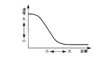
次に、ボール21の速度について説明する。ボール21の速度は、図15に示すように、ボール移動距離に従って減速するが完全には停止せず、0以上の最低速度を維持するようになっている。これにより、ボール21が停止していかなるキャラクタも接触できない状態になることを回避することができると共に、スピード感を増してゲームとしてのエンターテインメント性を向上することができる。
【0048】
次に、ゲームのリアリティ感を増すための陰影処理について説明する。一般にフィールド内でキャラクタが移動するようなサッカーゲームや野球ゲームのような場合、キャラクタに影を付けることより立体的になることが知られている。通常は図16(a)に示すように、キャラクタ20に対して単純に斜めにずらした影20aを付けることが行われてきた。これに対し、本実施態様では、影のリアル感を更に高めるため、図16(b)に示すように、斜めに平行移動して影を形成し、さらに、その影の形を斜めに変形させて影20bを形成している。図17は、矢印方向の光に対して種々の方向に向いたキャラクタ20の陰影を示している。これにより、単に斜めにずらすよりリアルな陰影を形成することができる。
【0049】
次に、ゲームのリアリティ感を増すための音量制御について説明する。プレーヤによるゲーム中にはリアリティ感を増すためにスピーカ180、181から歓声を出力するが、本実施形態ではフィールド内のボールの位置に応じて歓声の音量を制御する。図18に示すように、サッカーフィールド30を、例えば、5つの領域30a、30b、30c、30d、30eに分割し、ボール21がフィールド中央に領域30cにあるときには小さな歓声を出力し、ボール21がゴールに近い領域30b、30dになると歓声が大きくなり、ボール21がペナルティエリア30a、30eになると歓声が最高音になる。
【0050】
本発明は上記実施形態に限らず種々の変形が可能である。
例えば、上記実施形態では、本発明をサッカーゲームを行うビデオゲーム装置に適用したが、モニタ画面を2人のプレーヤが挟んでプレイする対戦型ゲームであれば、ホッケーゲーム等の他のゲームに適用してもよい。
また、ロゴの回転表示等は、対戦型ゲームに限らず他の種類のゲームに適用してもよい。
【0051】
更に、ロゴ以外の表示、例えば、ゴールの表示や得点の表示等の特定の表示に本発明の表示方法を適用して演出効果を高めるようにしてもよい。
【0052】
【発明の効果】
以上説明したように、本発明によれば、モニタ画面を挟んで2人のプレーヤが対向して対戦するビデオゲーム装置の表示方法において、ゲーム画像を、前記プレーヤの双方からみて正対して前記モニタ画面に表示するようにしたので、対向するプレーヤのいずれの側からも容易にゲーム画像が確認することができる。
【0053】
また、特定の表示を表示する際に、モニタ画面の一方の側から見て正対する第1の表示態様と、モニタ画面の他方の側から見て正対する第2の表示態様とで、モニタ画面のいずれかの側からも認識できない第3の表示態様を介して交互に表示し、第1の表示態様又は第2の表示態様と第3の表示態様との間の移行時には、第1の表示態様又は第2の表示態様を変形するようにすれば、特定の表示を効果的に演出して表示することができる。
【0054】
さらに、第1の表示態様又は第2の表示態様と第3の表示態様との間の移行時に、特定の表示がモニタ画面に平行な回転軸を中心として回転しているように変形すれば、それぞれのプレーヤに正対する第1及び第2の表示形態を、プレーヤに違和感を与えることなくモニタ画面に表示することができる。
また、本発明によれば、ビデオゲーム装置は、モニタ画面を有するゲーム機本体と、ゲーム機本体より双方のプレーヤに向けて突出し、前後に摺動及び/又は左右に回転可能に支持された複数の操作スティックとを有し、各プレーヤは、複数の操作スティックによりモニタ画面に表示されたキャラクタを操作して、モニタ画面に表示されるボールを打撃するようにしたので、複数の操作スティックをゲーム機のコントローラとするため、サッカープレーヤをロッドで操作する機械式の対戦型ゲーム装置の感覚を以ってプレイでき、ゲーム内容が理解しやすい。
【図面の簡単な説明】
【図1】本発明の一実施形態によるサッカーゲーム装置の外観図である。
【図2】本発明の一実施形態によるサッカーゲーム装置のブロック図である。
【図3】本発明の一実施形態によるサッカーゲーム装置のモニタ画面に表示される初期画面を示す図である。
【図4】図3の初期画面におけるロゴ表示の経時変化の説明図である。
【図5】図3の初期画面におけるロゴ表示方法のフローチャートである。
【図6】図3の初期画面におけるロゴ表示の経時変化の他の例説明図である。
【図7】本発明の一実施形態によるサッカーゲーム装置のゲーム操作説明画面例を示す図である。
【図8】本発明の一実施形態によるサッカーゲーム装置のキャラクタの可動範囲を示す図である。
【図9】本発明の一実施形態によるサッカーゲーム装置におけるスティックの動作とこれに対応するキャラクタの動きを示した図である。
【図10】本発明の一実施形態によるサッカーゲーム装置におけるキャラクタの動きとボールの反射方向を示した図である。
【図11】本発明の一実施形態によるサッカーゲーム装置におけるキャラクタとボールの進行方向の関係を示した説明図である。
【図12】本発明の一実施形態によるサッカーゲーム装置における回転するキャラクタとボールの進行方向の関係を示した説明図である。
【図13】本発明の一実施形態によるサッカーゲーム装置におけゴールキーパの可動方向およびその動きを示す図である。
【図14】本発明の一実施形態によるサッカーゲーム装置におけるサッカーフィールドのサイドラインに当たるボールの軌跡を示した図である。
【図15】本発明の一実施形態によるサッカーゲーム装置におけるキック後のボールの速度と距離の関係を示したグラフである。
【図16】キャラクタの陰影形成のための原理図である。
【図17】図16の原理によって陰影処理されたキャラクタの陰影を示す図である。
【図18】本発明の一実施形態によるサッカーゲーム装置における歓声の音量制御の説明図である。
【符号の説明】
1…サッカーゲーム装置
2…ゲーム装置本体
3…モニタ画面
4…操作盤
5…スティック
10…CPUブロック
11…ビデオブロック
12…サウンドブロック
14…ロゴ
20…キャラクタ
21…サッカーボール
30…サッカーフィールド[0001]
BACKGROUND OF THE INVENTION
The present invention relates to a video game apparatus that plays a game using video displayed on a monitor screen such as a CRT, and more particularly to a method for displaying various videos on a monitor screen and a game control method.
[0002]
[Prior art]
Video game apparatuses are known in which a plurality of players compete for a game using a single monitor screen, such as a competitive shooting game and a competitive block breaking game. Even in a video game device in which a player sits on both sides of one monitor screen and battles with the monitor screen in between, as in a competitive block breaking game, a coin slot is usually provided on either player side. In the vicinity of the coin slot, there is also a select button that allows selection of one-player or two-player play. In such a battle-type game, the controller for operating the character on the monitor is arranged in the same manner on both sides of the monitor.
[0003]
In a general video game device, in a state waiting for a player to insert a coin, in addition to characters for prompting the user to insert a coin, a logo or high score of a game maker may be displayed on the monitor screen. In the subsequent game initial stage, an image explaining the operation method of the controller is output at the start of the game. Such a game initial screen is generally configured on the assumption that it is viewed from the side of the game machine provided with a coin slot.
[0004]
[Problems to be solved by the invention]
However, in such a competitive video game apparatus as described above, if such a one-sided arrangement is used, characters and logos are reversed and give a sense of incongruity to players who face each other. In addition, if the displayed image is unilaterally arranged such that the displayed image is related to the game play content itself, such as a controller operation method, the facing player temporarily moves to the coin insertion side and displays the screen. Must be understood, and problems such as taking time to start play occur.
[0005]
In addition, soccer games and hockey games that compete for scores by operating a ball with a plurality of operation sticks are well known as competitive mechanical game devices. The player is required to operate a plurality of operation sticks well, has a side as an athletic competition, and has become a popular game game center.
[0006]
If such a mechanical battle type game device is converted into a video game, it is possible to produce effects such as screen display and game control that are impossible with a mechanical game, and it is expected to become popular as a video game device.
An object of the present invention is to provide a display method for a video game apparatus in which a game image can be easily recognized from either side of a player in a competitive video game apparatus.
[0007]
Another object of the present invention is to provide a method for controlling a video game apparatus in which a mechanical battle type game apparatus is converted into a video game.
[0008]
[Means for Solving the Problems]
The above object is a display method of a video game apparatus in which two players face each other across a monitor screen, and displays a game image on the monitor screen as seen from both players. This is achieved by the video game device display method characterized. Thereby, the game image can be easily confirmed from either side of the opposing player.
[0009]
In the above-described display method of the video game apparatus, the game image may include a game standby image displayed when waiting for the start of the game.
In the display method of the video game apparatus described above, the game image may include an operation explanation screen displayed by dividing the monitor screen so as to face each player. In this case, an operation explanation message is provided in a face-to-face manner with respect to both players, and the game can be started smoothly after inserting coins.
[0010]
In the above-described display method of the video game apparatus, the game image includes a specific display, and the specific display is a first display mode in which the game image is viewed from one side of the monitor screen, and the monitor screen. Displayed alternately through a third display mode that cannot be recognized from either side of the monitor screen, with the second display mode facing directly from the other side, and from the first display mode to the first display mode When shifting to the third display mode, when shifting from the third display mode to the first display mode, the first display mode is changed and shifted, and the second display mode is changed to the first display mode. When shifting to the third display mode, when shifting from the third display mode to the second display mode, the second display mode may be modified and shifted. Thereby, a game screen can be produced effectively.
[0011]
In the display method described above, when shifting from the first display mode to the third display mode, or when shifting from the third display mode to the first display mode, the specific display is the monitor. When the first display mode is deformed so as to rotate about a rotation axis parallel to the screen and the third display mode is shifted from the second display mode, the third display mode is changed. When shifting to the second display mode, the second display mode may be modified so that the specific display rotates about a rotation axis parallel to the monitor screen. As a result, the first and second display forms that face each player can be displayed on the monitor screen without causing the player to feel uncomfortable.
[0012]
The above object is a method for controlling a video game apparatus in which two players face each other across a monitor screen, the video game apparatus comprising: a game machine main body having the monitor screen; and the game machine main body. A plurality of operation sticks protruding toward both players and supported so as to slide back and forth and / or rotate left and right, and each player is displayed on the monitor screen by the plurality of operation sticks. The present invention is achieved by a control method for a video game device, wherein a character is operated to hit a ball displayed on the monitor screen. Thereby, since a plurality of operation sticks are used as a controller of the game machine, it is possible to play with a sense of a mechanical battle type game apparatus in which a player operates with a rod, and the contents of the game are easy to understand.
[0013]
In the video game device control method described above, it is preferable that the moving speed of the hit ball is based on the sliding speed of the operation stick at the time of hitting. Thereby, the speed of the hit ball can be easily adjusted, and the operational feeling can be improved.
In the control method of the video game apparatus described above, when the rotation speed of the operation stick is equal to or higher than a predetermined value, when the ball is within the hittable range, the hit ball floats above the field and the ball can be hit When it is out of range, it is desirable that the character slides in the rotation direction. Thereby, it is possible to change the game operation, and to realize a game full of interest with change.
[0014]
In the video game device control method described above, when the ball hits from the front of the character, the reflection angle of the ball may be equal to the incident angle to the character.
In the video game device control method described above, when the ball hits from behind the character, the ball may move so as to be refracted and passed by the character.
[0015]
In the video game device control method described above, when the character is moving back and forth, the reflection angle or the refraction angle of the ball may change based on the moving speed of the character back and forth. .
By controlling in this way, the trajectory of the ball can be predicted to some extent, the trajectory of the ball can be freely changed by a stick operation, and the entertainability of the game can be improved.
[0016]
In the video game device control method described above, it is desirable that the moving speed of the ball be gradually reduced according to the moving distance after the hit. Since this is close to the actual movement of the ball, this can enhance the sense of reality as a game.
In the video game device control method described above, it is desirable that the minimum velocity of the ball does not become zero. Thereby, it can be avoided that the ball stops and the game is interrupted outside the movable range of the character.
[0017]
In the video game device control method described above, it is desirable to change the cheering sound in accordance with the position of the ball so that the position of the ball becomes larger as it approaches the goal post. Thereby, the sense of reality of the game can be increased.
[0018]
DETAILED DESCRIPTION OF THE INVENTION
A soccer game device according to an embodiment of the present invention will be described with reference to the drawings.
FIG. 1 is an external view of the soccer game device according to the present embodiment. In FIG. 1, the
[0019]
Further, a
FIG. 2 is a block diagram for controlling the operation of the
[0020]
The
The CPU block 10 includes an SCU (System Control Unit) 100, a
[0021]
The
The
[0022]
Corresponding to each
[0023]
The
The video block 11 operates as a part of the display control means, and performs VDP (Video Display Processor) 120 for generating a game image, image synthesis for a background image (soccer field), shading processing described later, and clipping.
[0024]
When generating an image of a soccer field to be displayed on the
[0025]
The
[0026]
The sound block 12 includes a
[0027]
Next, each image generation process performed by the
FIG. 3 shows a specific example of a standby image in a state before starting the game, for example, in a state where the player is waiting in the game center or the like. Here, a
[0028]
When two players sandwich and play a
FIG. 4 shows changes over time of the logo displayed on the
[0029]
As shown in FIG. 4A, in the present embodiment, the
Here, when the rotation angle A around the x-axis is 0 degree, it is set to face one player in the largest form. The
[0030]
FIG. 5 is a flowchart of the logo display routine described above. A program for executing this display routine is stored in a predetermined area of the
The logo display routine is executed when, for example, the operating state of the CPU block 10 is detected and the
[0031]
When the logo display routine starts, first, the logo rotation angle A is advanced by 2 degrees in a predetermined unit time (step S1), and the
Next, it is determined whether or not the current logo rotation angle A has reached 90 degrees corresponding to the upper straight line display in FIG. 4 (a display mode that cannot be recognized from either side of the monitor screen) (step). S3). If it is determined in step S3 that the angle does not reach 90 degrees, the process returns to step S1, and the processes in steps S1 and S2 are repeated.
[0032]
If it is determined in step S3 that the angle has reached 90 degrees, an operation is performed to invert the
If the logo is reversed in this way, the process proceeds to step S5, where the logo rotation angle A is advanced by 2 degrees in a predetermined unit time (step S5), and the logo corresponding to the rotation angle A at that time. Display processing is performed (step S6).
[0033]
Next, it is determined whether or not the current logo rotation angle A has reached 270 degrees corresponding to the lower straight line display in FIG. 4 (a display mode that cannot be recognized from either side of the monitor screen) ( Step S7). If it is determined in step S7 that the angle does not reach 270 degrees, the process returns to step S5, and the processes in steps S5 and S6 are repeated.
[0034]
If it is determined in step S7 that the angle has reached 270 degrees, the
If the logo is reversed in this way, the process returns to step S1 and the above-described processing is repeated.
[0035]
As described above, in the
[0036]
The logo display pattern is not limited to the rotation display as described above, and, for example, contraction display and enlarged display may be repeated. That is, as shown in FIG. 6, the logo display facing one side is shrunk to shift to a straight line display, and the straight line display is enlarged again to shift to the logo display facing the other side. Good.
Also, on the initial screen of FIG. 3, the operation explanation screen of FIG. 7, and the like, the characters displayed in front of each player are displayed so as to face each player.
[0037]
In addition, when an area of a certain area is required for display for each player as in the operation explanation screen of FIG. 7, it is divided into a form necessary for display at the center of the screen as shown in FIG. It is preferable that each area is displayed facing each player so that the player can easily understand the playing method.
Next, an operation method of the
[0038]
In the
[0039]
The relationship between the operation of the
[0040]
The ball operation by the
[0041]
Further, when the
Furthermore, for an operation such as pushing the
[0042]
11 and 12 model some examples of such reflection and refraction actions of the
When the
[0043]
When the direction of the
Although the movement of the
[0044]
Next, the relationship between the action of the
As shown in FIG. 13, when the
[0045]
As long as the goalkeeper contacts the
[0046]
Next, the locus of the
[0047]
Next, the speed of the
[0048]
Next, shading processing for increasing the reality of the game will be described. In general, in a soccer game or a baseball game in which a character moves in a field, it is known that the character becomes three-dimensional by adding a shadow. Usually, as shown in FIG. 16A, a
[0049]
Next, volume control for increasing the sense of reality of the game will be described. During the game by the player, cheers are output from the
[0050]
The present invention is not limited to the above embodiment, and various modifications can be made.
For example, in the above-described embodiment, the present invention is applied to a video game device that performs a soccer game. May be.
Further, the logo rotation display or the like may be applied not only to the battle game but also to other types of games.
[0051]
Furthermore, the display method of the present invention may be applied to a display other than the logo, for example, a specific display such as a goal display or a score display to enhance the effect.
[0052]
【The invention's effect】
As described above, according to the present invention, in the display method of a video game apparatus in which two players face each other across the monitor screen, the game image is viewed from both the players facing the monitor. Since it is displayed on the screen, the game image can be easily confirmed from either side of the opposing player.
[0053]
In addition, when displaying a specific display, the monitor screen has a first display mode that faces directly from one side of the monitor screen and a second display mode that faces directly from the other side of the monitor screen. Are alternately displayed via the third display mode that cannot be recognized from either side, and the first display mode or the second display mode and the transition between the third display mode are displayed in the first display mode. If the aspect or the second display aspect is modified, a specific display can be effectively produced and displayed.
[0054]
Furthermore, when the first display mode or the transition between the second display mode and the third display mode is changed so that the specific display is rotated around a rotation axis parallel to the monitor screen, The first and second display forms that face each player can be displayed on the monitor screen without causing the player to feel uncomfortable.
In addition, according to the present invention, a video game apparatus includes a game machine main body having a monitor screen, and a plurality of video game apparatuses supported so as to protrude from the game machine main body toward both players and slide back and forth and / or rotate left and right. Since each player operates a character displayed on the monitor screen with a plurality of operation sticks and hits a ball displayed on the monitor screen, each player can play a plurality of operation sticks. Since it is a machine controller, it can be played with the sense of a mechanical competitive game device in which a soccer player is operated with a rod, and the game content is easy to understand.
[Brief description of the drawings]
FIG. 1 is an external view of a soccer game device according to an embodiment of the present invention.
FIG. 2 is a block diagram of a soccer game device according to an embodiment of the present invention.
FIG. 3 is a diagram showing an initial screen displayed on the monitor screen of the soccer game device according to the embodiment of the present invention.
4 is an explanatory diagram of a change over time in logo display on the initial screen of FIG. 3;
5 is a flowchart of a logo display method on the initial screen of FIG.
6 is a diagram for explaining another example of a change over time in logo display on the initial screen in FIG. 3;
FIG. 7 is a diagram showing a game operation explanation screen example of the soccer game device according to the embodiment of the present invention.
FIG. 8 is a view showing a movable range of a character of the soccer game device according to the embodiment of the present invention.
FIG. 9 is a diagram showing a stick movement and a corresponding character movement in the soccer game device according to the embodiment of the present invention;
FIG. 10 is a view showing a character movement and a ball reflection direction in the soccer game device according to the embodiment of the present invention;
FIG. 11 is an explanatory diagram showing a relationship between a character and a traveling direction of a ball in the soccer game device according to the embodiment of the present invention.
FIG. 12 is an explanatory diagram showing a relationship between a rotating character and a moving direction of a ball in the soccer game device according to the embodiment of the present invention.
FIG. 13 is a diagram showing a moving direction and a movement of the goal keeper in the soccer game device according to the embodiment of the present invention.
FIG. 14 is a diagram showing a trajectory of a ball hitting a side line of a soccer field in the soccer game device according to one embodiment of the present invention.
FIG. 15 is a graph showing the relationship between the speed and distance of a ball after kicking in the soccer game device according to one embodiment of the present invention.
FIG. 16 is a principle diagram for forming a shadow of a character.
FIG. 17 is a diagram showing the shadow of a character that has been subjected to a shadow process according to the principle of FIG. 16;
FIG. 18 is an explanatory diagram of cheer volume control in the soccer game device according to the embodiment of the present invention;
[Explanation of symbols]
1 ... Soccer game machine
2 ... Game device itself
3. Monitor screen
4 ... Control panel
5 ... Stick
10 ... CPU block
11 ... Video block
12 ... Sound Block
14 ... Logo
20 ... Character
21 ... Soccer ball
30 ... Soccer field
Claims (4)
前記特定の画像の表示は、前記モニタ画面の一方の側から見て正対する第1の表示態様と、前記一方の側に対向する他方の側から見て正対する第2の表示態様とが交互に表示されるものであり、
前記表示ルーチンは、
前記特定の画像を前記第1の表示態様から前記モニタ画面に平行な回転軸であるX軸周りに回転させて前記モニタ画面に表示する第1のステップと、
前記特定の画像が前記第1の表示態様から90度回転したか否かを判定する第2のステップと、
前記第2のステップで90度に達していないと判断されたとき、前記第1のステップと前記第2のステップとを繰り返すステップと、
前記第2のステップで90度に達していると判断されたとき、前記特定の画像を前記X軸に垂直であって前記モニタ画面に垂直なY軸周りに180度反転させるステップと、
Y軸周りに180度反転させた前記特定の画像を前記第2の表示態様へとX軸周りに回転させて前記モニタ画面に表示するステップと
を有することを特徴とするビデオゲーム装置の画像表示方法。An image display method of a video game apparatus in which a specific image is displayed on a monitor screen by a CPU executing a display routine of a video game program, and a player positioned opposite to the monitor screen plays a game,
As for the display of the specific image, a first display mode that faces directly from one side of the monitor screen and a second display mode that faces directly from the other side facing the one side are alternated. Displayed on the
The display routine includes
A first step of rotating the specific image from the first display mode around the X axis, which is a rotation axis parallel to the monitor screen, and displaying the specific image on the monitor screen ;
A second step of determining whether the specific image has been rotated 90 degrees from the first display mode;
Repeating the first step and the second step when it is determined in the second step that the angle does not reach 90 degrees;
Reversing the specific image by 180 degrees about the Y axis perpendicular to the X axis and perpendicular to the monitor screen when it is determined in the second step that the angle reaches 90 degrees;
An image display of a video game device, comprising: rotating the specific image reversed 180 degrees around the Y axis to the second display mode around the X axis and displaying the image on the monitor screen. Method.
前記特定の画像の表示は、前記モニタ画面の一方の側から見て正対する第1の表示態様と、前記一方の側に対向する他方の側から見て正対する第2の表示態様とが、前記特定の画像が直線表示される第3の表示態様を介して交互に表示されるものであり、
前記表示ルーチンは、
前記特定の画像を前記第1の表示態様から前記第3の表示態様へ、前記モニタ画面に平行な回転軸であるX軸周りに回転させて前記モニタ画面に表示する第1のステップと、
前記特定の画像が前記第1の表示態様から前記第3の表示態様に達したか否かを判定する第2のステップと、
前記第3の表示態様に達していないと判断されたとき、前記第1のステップと前記第2のステップとを繰り返すステップと、
前記第3の表示態様に達していると判断されたとき、前記特定の画像を前記X軸に垂直であって前記モニタ画面に垂直なY軸周りに180度反転させるステップと、
Y軸周りに180度反転させた前記特定の画像を前記第2の表示態様へとX軸周りに回転させて前記モニタ画面に表示するステップと
を有することを特徴とするビデオゲーム装置の画像表示方法。An image display method for a video game apparatus in which a specific image is displayed on a monitor screen by a CPU executing a display routine of a video game program, and a player positioned opposite to the monitor screen to play a game. ,
The display of the specific image includes a first display mode facing directly from one side of the monitor screen and a second display mode facing directly from the other side facing the one side. The specific image is alternately displayed via a third display mode in which the line is displayed ;
The display routine includes
A first step of rotating the specific image from the first display mode to the third display mode around the X axis, which is a rotation axis parallel to the monitor screen, and displaying the specific image on the monitor screen;
A second step of determining whether the specific image has reached the third display mode from the first display mode;
Repeating the first step and the second step when it is determined that the third display mode has not been reached;
When it is determined that the third display mode has been reached, the specific image is inverted 180 degrees around the Y axis perpendicular to the X axis and perpendicular to the monitor screen ;
An image display of a video game device, comprising: rotating the specific image reversed 180 degrees around the Y axis to the second display mode around the X axis and displaying the image on the monitor screen. Method.
前記特定の画像の表示は、前記モニタ画面の一方の側から見て正対する第1の表示態様と、前記一方の側に対向する他方の側から見て正対する第2の表示態様とが交互に表示されるものであり、
前記特定の画像を前記第1の表示態様から前記モニタ画面に平行な回転軸であるX軸周りに回転させて前記モニタ画面に表示する処理を実行する手段と、前記特定の画像が前記第1の表示態様から90度回転していると判断したとき、前記特定の画像を前記X軸に垂直であって前記モニタ画面に垂直なY軸周りに180度反転させて前記モニタ画面に表示する処理を実行する手段と、Y軸周りに180度反転させた前記特定の画像を前記第2の表示態様へとX軸周りに回転させて前記モニタ画面に表示する処理を実行する手段とを有する
ことを特徴とするビデオゲーム装置。A video game apparatus having a monitor screen and a CPU, wherein a specific image is displayed on the monitor screen, and two players face each other across the monitor screen,
As for the display of the specific image, a first display mode that faces directly from one side of the monitor screen and a second display mode that faces directly from the other side facing the one side are alternated. Displayed on the
Means for rotating the specific image from the first display mode around the X axis, which is a rotation axis parallel to the monitor screen, and displaying the specific image on the monitor screen; and When the display mode is determined to be rotated 90 degrees, the specific image is displayed on the monitor screen by being inverted 180 degrees around the Y axis perpendicular to the X axis and perpendicular to the monitor screen. means for executing, to have a means for the specific image is inverted 180 degrees about the Y-axis is rotated about the X axis to the second display mode to execute a process of displaying on the monitor screen A video game apparatus characterized by.
前記特定の画像の表示は、前記モニタ画面の一方の側から見て正対する第1の表示態様と、前記一方の側に対向する他方の側から見て正対する第2の表示態様とが、前記特定の画像が直線表示される第3の表示態様を介して交互に表示されるものであり、
前記特定の画像を前記第1の表示態様から前記第3の表示態様へ、前記モニタ画面に平行な回転軸であるX軸周りに回転させて前記モニタ画面に表示する処理を実行する手段と、前記特定の画像が前記第1の表示態様から前記第3の表示態様に達していると判断したとき、前記特定の画像を前記X軸に垂直であって前記モニタ画面に垂直なY軸周りに180度反転させて前記モニタ画面に表示する処理を実行する手段と、Y軸周りに180度反転させた前記特定の画像を前記第2の表示態様へとX軸周りに回転させて前記モニタ画面に表示する処理を実行する手段とを有する
ことを特徴とするビデオゲーム装置。A video game apparatus having a monitor screen and a CPU, wherein a specific image is displayed on the monitor screen, and two players face each other across the monitor screen,
The display of the specific image includes a first display mode facing directly from one side of the monitor screen and a second display mode facing directly from the other side facing the one side. The specific image is alternately displayed via a third display mode in which the line is displayed ;
Means for executing processing for rotating the specific image from the first display mode to the third display mode around the X axis, which is a rotation axis parallel to the monitor screen, and displaying it on the monitor screen; When it is determined that the specific image has reached the third display mode from the first display mode, the specific image is set around the Y axis that is perpendicular to the X axis and perpendicular to the monitor screen. Means for executing a process of reversing 180 degrees and displaying the image on the monitor screen; and rotating the specific image reversed 180 degrees around the Y axis around the X axis to the second display mode. And a means for executing a process of displaying on the video game device.
Priority Applications (2)
| Application Number | Priority Date | Filing Date | Title |
|---|---|---|---|
| JP03241897A JP3677924B2 (en) | 1997-02-17 | 1997-02-17 | Display method and control method of video game apparatus |
| US09/024,107 US6176780B1 (en) | 1997-02-17 | 1998-02-17 | Two-player video game with method of displaying logos and instructions in a manner readable by both players |
Applications Claiming Priority (1)
| Application Number | Priority Date | Filing Date | Title |
|---|---|---|---|
| JP03241897A JP3677924B2 (en) | 1997-02-17 | 1997-02-17 | Display method and control method of video game apparatus |
Publications (2)
| Publication Number | Publication Date |
|---|---|
| JPH10225572A JPH10225572A (en) | 1998-08-25 |
| JP3677924B2 true JP3677924B2 (en) | 2005-08-03 |
Family
ID=12358409
Family Applications (1)
| Application Number | Title | Priority Date | Filing Date |
|---|---|---|---|
| JP03241897A Expired - Fee Related JP3677924B2 (en) | 1997-02-17 | 1997-02-17 | Display method and control method of video game apparatus |
Country Status (2)
| Country | Link |
|---|---|
| US (1) | US6176780B1 (en) |
| JP (1) | JP3677924B2 (en) |
Families Citing this family (22)
| Publication number | Priority date | Publication date | Assignee | Title |
|---|---|---|---|---|
| GB2352641B (en) * | 1999-07-28 | 2003-09-24 | Big Fish Entertainment Ltd | Video game |
| GB2353583A (en) * | 1999-08-25 | 2001-02-28 | Edward John Lindsay Hands | Computer interface for a group of users |
| JP4030249B2 (en) | 2000-05-19 | 2008-01-09 | 株式会社コナミデジタルエンタテインメント | Computer-readable recording medium recording action game program, action game device and control method thereof |
| FR2813804B1 (en) * | 2000-09-08 | 2004-01-23 | Sylvius | MULTI-USER ELECTRONIC SCREEN PLATFORM, ESPECIALLY FOR GAMES |
| DE10329181A1 (en) * | 2003-06-27 | 2005-01-20 | Albert-Ludwigs-Universität Freiburg, vertreten durch den Rektor | Apparatus and method for inputting control signals in a computer based simmulated table football game |
| EP1594119A3 (en) * | 2004-05-06 | 2007-10-31 | Canon Kabushiki Kaisha | Image signal processing circuit and image display apparatus |
| US7690653B2 (en) * | 2004-12-03 | 2010-04-06 | Steven Mark Simon | Foosball table |
| US20060156249A1 (en) * | 2005-01-12 | 2006-07-13 | Blythe Michael M | Rotate a user interface |
| KR100703331B1 (en) * | 2005-06-01 | 2007-04-03 | 삼성전자주식회사 | Method of character inputting given a visual effect to character inputting and the mobile terminal terefor |
| US7578505B2 (en) * | 2006-01-25 | 2009-08-25 | Mattel, Inc. | Electronic game device with hand and foot controls |
| JP2008052374A (en) * | 2006-08-22 | 2008-03-06 | Sega Corp | Method and device for controlling collision model in virtual space |
| US20110300932A1 (en) * | 2007-06-05 | 2011-12-08 | Henderson Byron M | Interactive display and use thereof |
| DE102008015361A1 (en) * | 2008-03-20 | 2009-09-24 | Full Moon Factory Ltd. | Operating device and arrangement for carrying out a digital game |
| JP2008183439A (en) * | 2008-04-28 | 2008-08-14 | Namco Bandai Games Inc | Sports game apparatus and method of controlling play in sports game |
| JP4775773B2 (en) * | 2008-04-28 | 2011-09-21 | 株式会社バンダイナムコゲームス | Sports game equipment |
| JP4775779B2 (en) * | 2009-03-27 | 2011-09-21 | 株式会社バンダイナムコゲームス | Sports game equipment |
| JP6369331B2 (en) * | 2012-12-19 | 2018-08-08 | ソニー株式会社 | Audio processing apparatus and method, and program |
| FR3025436A1 (en) * | 2014-09-05 | 2016-03-11 | Joann Ameline | GAME DEVICE PROVIDED WITH AN INTERACTIVE SURFACE FOR MOVING A PROJECTILE |
| FR3025904B1 (en) * | 2014-09-17 | 2016-12-09 | 3 Axes Inst | INTERACTIVE CONTROL DEVICE FOR VIDEO GAME |
| US10821363B2 (en) * | 2017-07-26 | 2020-11-03 | King.Com Ltd. | Method and apparatus for providing a computer implemented game |
| US11745107B2 (en) | 2017-07-26 | 2023-09-05 | King.Com Ltd. | Method and apparatus for providing a computer implemented game |
| CH714665A1 (en) * | 2018-02-19 | 2019-08-30 | Kynoa Sa | Entertainment device for the interactive practice of a video game. |
Family Cites Families (19)
| Publication number | Priority date | Publication date | Assignee | Title |
|---|---|---|---|---|
| USRE28507E (en) * | 1969-05-27 | 1975-08-05 | Television gaming apparatus | |
| US3874669A (en) * | 1973-03-26 | 1975-04-01 | Rosalba Ariano | Electronic device for the simulation of an animated game, in particular the game of football |
| US3921161A (en) * | 1973-05-29 | 1975-11-18 | Sanders Associates Inc | Preprogrammed television gaming system |
| IT1018380B (en) * | 1974-07-23 | 1977-09-30 | Zanussi A Spa Industrie | IMPROVEMENT OF ELECTRIC CIRCUITS FOR THE GENERATION OF SPECIAL EFFECTS IN SYMBOL DISPLAY SYSTEMS ON A CINESCOPE PARTIALLY FOR TELEVISION GAMES |
| US4034983A (en) * | 1975-12-11 | 1977-07-12 | Massachusetts Institute Of Technology | Electronic games |
| US4093223A (en) * | 1976-01-23 | 1978-06-06 | Wilke William F | Electronic game apparatus and method |
| US4386776A (en) * | 1981-02-17 | 1983-06-07 | Coleco Industries, Inc. | Electronic sports-action game with improved game-object simulation |
| US4570158A (en) * | 1981-10-27 | 1986-02-11 | Williams Electronics, Inc. | Horizontal and vertical image inversion circuit for a video display |
| US4710873A (en) * | 1982-07-06 | 1987-12-01 | Marvin Glass & Associates | Video game incorporating digitized images of being into game graphics |
| JP2526857B2 (en) * | 1984-12-27 | 1996-08-21 | ソニー株式会社 | Image signal conversion method |
| US4713007A (en) * | 1985-10-11 | 1987-12-15 | Alban Eugene P | Aircraft controls simulator |
| US4691920A (en) * | 1986-01-10 | 1987-09-08 | Murphy Dale P | Electronic hockey game |
| US4797836A (en) * | 1986-11-19 | 1989-01-10 | The Grass Valley Group, Inc. | Image orientation and animation using quaternions |
| USD314985S (en) * | 1988-02-12 | 1991-02-26 | Monneret Jouets | Game table |
| US4952051A (en) * | 1988-09-27 | 1990-08-28 | Lovell Douglas C | Method and apparatus for producing animated drawings and in-between drawings |
| JP3052681B2 (en) * | 1993-08-06 | 2000-06-19 | 松下電器産業株式会社 | 3D video generation device |
| US5563625A (en) * | 1994-09-08 | 1996-10-08 | Ibm Corporation | Fast 180 degree image rotation and reversal |
| JP3376726B2 (en) * | 1994-11-11 | 2003-02-10 | 富士通株式会社 | Bigraphic drawing display device |
| US5850229A (en) * | 1995-12-15 | 1998-12-15 | Raindrop Geomagic, Inc. | Apparatus and method for geometric morphing |
-
1997
- 1997-02-17 JP JP03241897A patent/JP3677924B2/en not_active Expired - Fee Related
-
1998
- 1998-02-17 US US09/024,107 patent/US6176780B1/en not_active Expired - Lifetime
Also Published As
| Publication number | Publication date |
|---|---|
| JPH10225572A (en) | 1998-08-25 |
| US6176780B1 (en) | 2001-01-23 |
Similar Documents
| Publication | Publication Date | Title |
|---|---|---|
| JP3677924B2 (en) | Display method and control method of video game apparatus | |
| JP3861928B2 (en) | Game image display method and control method | |
| US7223169B2 (en) | Program for controlling execution of a game, and a game machine for executing the program | |
| JP5436773B2 (en) | Program and game device | |
| JP5436772B2 (en) | Program and game device | |
| JP4114029B2 (en) | Image processing apparatus, image processing method, and recording medium | |
| US20060276241A1 (en) | Game program, game device, and game method | |
| JP2002000939A (en) | Electronic game device, method therefor and storage medium | |
| JP3740797B2 (en) | Baseball game image display method | |
| JP2003519547A (en) | Computer for executing a game using pressure-sensitive controller, method of using the same, and recording medium therefor | |
| JP2000157745A (en) | Game machine, game control and recording medium having recorded program | |
| US20080070654A1 (en) | Game Device | |
| JP3885381B2 (en) | Game image display method | |
| JP2002301267A (en) | Method for controlling baseball game, game program, recoding medium and game machine | |
| JP4039776B2 (en) | Ball paddle game machine | |
| JP4320352B2 (en) | GAME DEVICE, GAME CONTROL PROGRAM, AND RECORDING MEDIUM CONTAINING THE SAME | |
| JP3594181B2 (en) | GAME DEVICE, GAME CONTROL METHOD, RECORDING MEDIUM | |
| JP3835477B2 (en) | Program for controlling execution of game and game apparatus for executing the program | |
| JP2002200348A (en) | Control method for baseball game, storage medium, and game device | |
| JP3720433B2 (en) | Game device operating method and game device | |
| JP2001198356A (en) | Game method, equipment and recording medium | |
| JP5356193B2 (en) | GAME DEVICE, GAME CONTROL PROGRAM, AND GAME CONTROL METHOD | |
| JP4753147B2 (en) | Image processing apparatus and program | |
| JP3897048B2 (en) | GAME DEVICE AND ITS CONTROL METHOD | |
| JP2002035416A (en) | Game device and information recording medium |
Legal Events
| Date | Code | Title | Description |
|---|---|---|---|
| A521 | Request for written amendment filed |
Free format text: JAPANESE INTERMEDIATE CODE: A523 Effective date: 20040213 |
|
| A621 | Written request for application examination |
Free format text: JAPANESE INTERMEDIATE CODE: A621 Effective date: 20040213 |
|
| A131 | Notification of reasons for refusal |
Free format text: JAPANESE INTERMEDIATE CODE: A131 Effective date: 20050125 |
|
| A521 | Request for written amendment filed |
Free format text: JAPANESE INTERMEDIATE CODE: A523 Effective date: 20050325 |
|
| TRDD | Decision of grant or rejection written | ||
| A01 | Written decision to grant a patent or to grant a registration (utility model) |
Free format text: JAPANESE INTERMEDIATE CODE: A01 Effective date: 20050419 |
|
| A61 | First payment of annual fees (during grant procedure) |
Free format text: JAPANESE INTERMEDIATE CODE: A61 Effective date: 20050502 |
|
| R150 | Certificate of patent or registration of utility model |
Free format text: JAPANESE INTERMEDIATE CODE: R150 |
|
| FPAY | Renewal fee payment (event date is renewal date of database) |
Free format text: PAYMENT UNTIL: 20090520 Year of fee payment: 4 |
|
| FPAY | Renewal fee payment (event date is renewal date of database) |
Free format text: PAYMENT UNTIL: 20090520 Year of fee payment: 4 |
|
| FPAY | Renewal fee payment (event date is renewal date of database) |
Free format text: PAYMENT UNTIL: 20100520 Year of fee payment: 5 |
|
| LAPS | Cancellation because of no payment of annual fees |