US4386776A - Electronic sports-action game with improved game-object simulation - Google Patents
Electronic sports-action game with improved game-object simulation Download PDFInfo
- Publication number
- US4386776A US4386776A US06/234,903 US23490381A US4386776A US 4386776 A US4386776 A US 4386776A US 23490381 A US23490381 A US 23490381A US 4386776 A US4386776 A US 4386776A
- Authority
- US
- United States
- Prior art keywords
- game
- symbol
- player
- simulated
- team
- Prior art date
- Legal status (The legal status is an assumption and is not a legal conclusion. Google has not performed a legal analysis and makes no representation as to the accuracy of the status listed.)
- Expired - Lifetime
Links
Images


Classifications
-
- A—HUMAN NECESSITIES
- A63—SPORTS; GAMES; AMUSEMENTS
- A63F—CARD, BOARD, OR ROULETTE GAMES; INDOOR GAMES USING SMALL MOVING PLAYING BODIES; VIDEO GAMES; GAMES NOT OTHERWISE PROVIDED FOR
- A63F13/00—Video games, i.e. games using an electronically generated display having two or more dimensions
- A63F13/80—Special adaptations for executing a specific game genre or game mode
- A63F13/812—Ball games, e.g. soccer or baseball
-
- A—HUMAN NECESSITIES
- A63—SPORTS; GAMES; AMUSEMENTS
- A63F—CARD, BOARD, OR ROULETTE GAMES; INDOOR GAMES USING SMALL MOVING PLAYING BODIES; VIDEO GAMES; GAMES NOT OTHERWISE PROVIDED FOR
- A63F3/00—Board games; Raffle games
- A63F3/00003—Types of board games
- A63F3/00028—Board games simulating indoor or outdoor sporting games, e.g. bowling, basketball, boxing, croquet, athletics, jeu de boules, darts, snooker, rodeo
-
- A—HUMAN NECESSITIES
- A63—SPORTS; GAMES; AMUSEMENTS
- A63F—CARD, BOARD, OR ROULETTE GAMES; INDOOR GAMES USING SMALL MOVING PLAYING BODIES; VIDEO GAMES; GAMES NOT OTHERWISE PROVIDED FOR
- A63F13/00—Video games, i.e. games using an electronically generated display having two or more dimensions
-
- A—HUMAN NECESSITIES
- A63—SPORTS; GAMES; AMUSEMENTS
- A63F—CARD, BOARD, OR ROULETTE GAMES; INDOOR GAMES USING SMALL MOVING PLAYING BODIES; VIDEO GAMES; GAMES NOT OTHERWISE PROVIDED FOR
- A63F13/00—Video games, i.e. games using an electronically generated display having two or more dimensions
- A63F13/40—Processing input control signals of video game devices, e.g. signals generated by the player or derived from the environment
- A63F13/42—Processing input control signals of video game devices, e.g. signals generated by the player or derived from the environment by mapping the input signals into game commands, e.g. mapping the displacement of a stylus on a touch screen to the steering angle of a virtual vehicle
-
- A—HUMAN NECESSITIES
- A63—SPORTS; GAMES; AMUSEMENTS
- A63F—CARD, BOARD, OR ROULETTE GAMES; INDOOR GAMES USING SMALL MOVING PLAYING BODIES; VIDEO GAMES; GAMES NOT OTHERWISE PROVIDED FOR
- A63F3/00—Board games; Raffle games
- A63F3/00643—Electric board games; Electric features of board games
-
- G—PHYSICS
- G05—CONTROLLING; REGULATING
- G05G—CONTROL DEVICES OR SYSTEMS INSOFAR AS CHARACTERISED BY MECHANICAL FEATURES ONLY
- G05G9/00—Manually-actuated control mechanisms provided with one single controlling member co-operating with two or more controlled members, e.g. selectively, simultaneously
- G05G9/02—Manually-actuated control mechanisms provided with one single controlling member co-operating with two or more controlled members, e.g. selectively, simultaneously the controlling member being movable in different independent ways, movement in each individual way actuating one controlled member only
- G05G9/04—Manually-actuated control mechanisms provided with one single controlling member co-operating with two or more controlled members, e.g. selectively, simultaneously the controlling member being movable in different independent ways, movement in each individual way actuating one controlled member only in which movement in two or more ways can occur simultaneously
- G05G9/047—Manually-actuated control mechanisms provided with one single controlling member co-operating with two or more controlled members, e.g. selectively, simultaneously the controlling member being movable in different independent ways, movement in each individual way actuating one controlled member only in which movement in two or more ways can occur simultaneously the controlling member being movable by hand about orthogonal axes, e.g. joysticks
- G05G9/04785—Manually-actuated control mechanisms provided with one single controlling member co-operating with two or more controlled members, e.g. selectively, simultaneously the controlling member being movable in different independent ways, movement in each individual way actuating one controlled member only in which movement in two or more ways can occur simultaneously the controlling member being movable by hand about orthogonal axes, e.g. joysticks the controlling member being the operating part of a switch arrangement
-
- H—ELECTRICITY
- H01—ELECTRIC ELEMENTS
- H01H—ELECTRIC SWITCHES; RELAYS; SELECTORS; EMERGENCY PROTECTIVE DEVICES
- H01H13/00—Switches having rectilinearly-movable operating part or parts adapted for pushing or pulling in one direction only, e.g. push-button switch
- H01H13/02—Details
- H01H13/12—Movable parts; Contacts mounted thereon
- H01H13/14—Operating parts, e.g. push-button
-
- A—HUMAN NECESSITIES
- A63—SPORTS; GAMES; AMUSEMENTS
- A63F—CARD, BOARD, OR ROULETTE GAMES; INDOOR GAMES USING SMALL MOVING PLAYING BODIES; VIDEO GAMES; GAMES NOT OTHERWISE PROVIDED FOR
- A63F2300/00—Features of games using an electronically generated display having two or more dimensions, e.g. on a television screen, showing representations related to the game
- A63F2300/20—Features of games using an electronically generated display having two or more dimensions, e.g. on a television screen, showing representations related to the game characterised by details of the game platform
- A63F2300/204—Features of games using an electronically generated display having two or more dimensions, e.g. on a television screen, showing representations related to the game characterised by details of the game platform the platform being a handheld device
-
- A—HUMAN NECESSITIES
- A63—SPORTS; GAMES; AMUSEMENTS
- A63F—CARD, BOARD, OR ROULETTE GAMES; INDOOR GAMES USING SMALL MOVING PLAYING BODIES; VIDEO GAMES; GAMES NOT OTHERWISE PROVIDED FOR
- A63F2300/00—Features of games using an electronically generated display having two or more dimensions, e.g. on a television screen, showing representations related to the game
- A63F2300/80—Features of games using an electronically generated display having two or more dimensions, e.g. on a television screen, showing representations related to the game specially adapted for executing a specific type of game
- A63F2300/8088—Features of games using an electronically generated display having two or more dimensions, e.g. on a television screen, showing representations related to the game specially adapted for executing a specific type of game involving concurrently several players in a non-networked game, e.g. on the same game console
-
- G—PHYSICS
- G05—CONTROLLING; REGULATING
- G05G—CONTROL DEVICES OR SYSTEMS INSOFAR AS CHARACTERISED BY MECHANICAL FEATURES ONLY
- G05G9/00—Manually-actuated control mechanisms provided with one single controlling member co-operating with two or more controlled members, e.g. selectively, simultaneously
- G05G9/02—Manually-actuated control mechanisms provided with one single controlling member co-operating with two or more controlled members, e.g. selectively, simultaneously the controlling member being movable in different independent ways, movement in each individual way actuating one controlled member only
- G05G9/04—Manually-actuated control mechanisms provided with one single controlling member co-operating with two or more controlled members, e.g. selectively, simultaneously the controlling member being movable in different independent ways, movement in each individual way actuating one controlled member only in which movement in two or more ways can occur simultaneously
- G05G9/047—Manually-actuated control mechanisms provided with one single controlling member co-operating with two or more controlled members, e.g. selectively, simultaneously the controlling member being movable in different independent ways, movement in each individual way actuating one controlled member only in which movement in two or more ways can occur simultaneously the controlling member being movable by hand about orthogonal axes, e.g. joysticks
- G05G2009/04703—Mounting of controlling member
- G05G2009/04733—Mounting of controlling member with a joint having a nutating disc, e.g. forced by a spring
-
- G—PHYSICS
- G05—CONTROLLING; REGULATING
- G05G—CONTROL DEVICES OR SYSTEMS INSOFAR AS CHARACTERISED BY MECHANICAL FEATURES ONLY
- G05G9/00—Manually-actuated control mechanisms provided with one single controlling member co-operating with two or more controlled members, e.g. selectively, simultaneously
- G05G9/02—Manually-actuated control mechanisms provided with one single controlling member co-operating with two or more controlled members, e.g. selectively, simultaneously the controlling member being movable in different independent ways, movement in each individual way actuating one controlled member only
- G05G9/04—Manually-actuated control mechanisms provided with one single controlling member co-operating with two or more controlled members, e.g. selectively, simultaneously the controlling member being movable in different independent ways, movement in each individual way actuating one controlled member only in which movement in two or more ways can occur simultaneously
- G05G9/047—Manually-actuated control mechanisms provided with one single controlling member co-operating with two or more controlled members, e.g. selectively, simultaneously the controlling member being movable in different independent ways, movement in each individual way actuating one controlled member only in which movement in two or more ways can occur simultaneously the controlling member being movable by hand about orthogonal axes, e.g. joysticks
- G05G2009/0474—Manually-actuated control mechanisms provided with one single controlling member co-operating with two or more controlled members, e.g. selectively, simultaneously the controlling member being movable in different independent ways, movement in each individual way actuating one controlled member only in which movement in two or more ways can occur simultaneously the controlling member being movable by hand about orthogonal axes, e.g. joysticks characterised by means converting mechanical movement into electric signals
- G05G2009/04744—Switches
Definitions
- the present invention is directed to electronic games, particularly those of the type in which the game action is simulated on a matrix of discrete visual-image-producing devices.
- an electronic sports-action game that includes a housing, a display panel on the upper surface of the housing, an operational-circuit means disposed inside the housing, and a control board on the housing that includes a multiplicity of manually operable control elements.
- the display panel includes a visual simulation of a playing field that is adapted to display symbols at discrete positions on the playing field between side and end boundary lines in response to electrical signals.
- the simulated playing field is of the type on which a game is played between two teams, each of which attempts to maneuver a game object into a goal associated with it and thereby achieve a score.
- the display panel simulates a goal associated with one team, the goal being located at a goal position that includes at least one of the discrete positions in that end of the playing field defended by the other team.
- the display panel also simulates another goal associated with the other team and located at a goal position that includes at least one of the discrete positions in that end of the playing field defended by the one team.
- the operational-circuit means is electrically connected to the display panel for generation and transmission of the electrical signals to the display panel to produce symbols on the simulated playing field.
- the symbols include offensive-player symbols, which simulate players of the team currently on offense, and defensive-player symbols, which simulate players of the team currently on defense.
- a game-object symbol which simulates a game object in two modes.
- the first mode is a control mode, in which the game-object symbol moves with an offensive-player symbol to simulate the game object under control of that simulated player.
- the other mode is an independent mode, in which the game-object symbol moves independently of the player symbols.
- the operational-circuit means includes means for moving at least one offensive-player symbol, at least one defensive-player symbol, and the game-object symbol about the playing field. It also includes coincidence-detection means and means for monitoring play action.
- the means for moving at least one offensive-player symbol moves the game-object symbol when the game object is simulated to be under control of the offensive-player symbol being moved.
- the game-object movement means is operable to move the game-object symbol independently of the player symbols when simulation of the game object is in the independent mode.
- the game-object movement means is operable to move the game object in a straight-line path to simulate a "pass" or a "shot" of the game object.
- the game-object movement means diverts the game-object symbol from its straight-line path when at least one of the boundary lines is encountered during independent motion, and it continues the independent motion of the game-object symbol along the boundary line.
- the coincidence-detection means detects coincidence between the game-object symbol and a goal position during a simulated shot from a player symbol of the team associated with the goal position. It thereby detects a score. In one of the illustrated embodiments, the coincidence-detection means also detects coincidence between the game-object symbol and the goal position associated with the team currently on offense while the game object is being simulated in the control mode. A score can thereby be made in both modes of game-object simulation. In that same embodiment, the coincidence-detection means also detects coincidence between a defensive-player symbol and the offensive-player symbol that has simulated control of the game object. Upon such detection, the game-object movement institutes the independent mode of game-object simulation.
- the means for monitoring play action records information concerning the status of the simulated game, and it produces signals indicative of the status information. Those signals convey the recorded information to an operator of the game.
- the manually operable control elements in the control board are connected to the operational-circuit means for transmission of the electrical signals to it through manual operation of the control elements. At least one of the manually operable control elements is operable to transmit signals to the operational-circuit means to produce manually controlled movement of at least one of the offensive-player symbols. Also, at least one of the manually operable control elements is operable to transmit signals to the operational-circuit means for production by the game-object movement means of the straight-line movement of the game-object symbol, the straight-line movement being independent of the movement of the player symbols.
- the straight-line motion is stopped by the game-object movement means upon independent movement of the game object to a predetermined number of positions along the straight-line path, the predetermined number being less than the number of discrete positions along the longer axis of the playing field.
- the game-object movement means then maintains the game-object symbol in a stationary position until coincidence with one of the player symbols, and play action is permitted to continue while the game-object symbol remains stationary.
- An operator can operate the manually operable control elements of such a game to move an offensive-player symbol having simulated control of the game-object symbol so as to avoid the defensive-player symbols while putting the offensive-player symbol into position for a "pass" or a "shot.”
- the operator can then operate a manually operable control element to cause a simulated shot at the goal position.
- the coincidence-detection means detects coincidence of the game-object symbol with at least one predetermined stationary position on the playing field during independent motion of the game-object symbol. Upon such detection, the game-object movement means initiates movement of the game-object symbol through a second predetermined number of discrete positions.
- the second predetermined number of discrete positions can be different from the first predetermined number of discrete positions.
- FIG. 1 is perspective view of a game device used to simulate the games of football, basketball, hockey, and soccer;
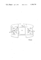
- FIG. 2 is an end view of the device of FIG. 1 showing its central cartridge removed;
- FIG. 3 is another end view, partly broken away, showing the cartridge in place
- FIG. 4 is a plan view of the device with a cartridge removed
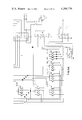
- FIGS. 5A and 5B constitute a schematic diagram of the circuitry employed to provide the game action of the device
- FIG. 6 is a cross-sectional view of a switch assembly employed in controlling the positions of the player symbols
- FIG. 7 is a view similar to FIG. 6 but only partly broken away, showing the switch lever in a tilted position
- FIG. 8 is a plan view of the switch assembly with parts removed
- FIG. 9 is an elevational view of the switch assembly partly broken away at line 9--9 of FIG. 8;
- FIG. 10 is a cross-sectional view of one of the keys on the control boards and its associated switch
- FIG. 11 is a perspective view of a game cartridge used for simulation of ice hockey
- FIG. 12 is a perspective view of a game cartridge used for simulation of basketball
- FIG. 13 is a perspective view of a game cartridge used for simulation of soccer
- FIGS. 14-20 are diagrams used to explain the play action of the ice-hockey version of the game.
- FIG. 21 is a similar diagram illustrating soccer.
- FIGS. 22-26 are similar diagrams used in connection with the description of basketball simulation.
- FIG. 1 illustrates an electronic game in which there are provided two switch assemblies, evidenced in FIG. 1 by levers 30 and 36, that are used to independently and simultaneously control player symbols on the same team.
- the device is employed to simulate American football, but FIGS. 2-4 illustrate that a central cartridge portion can be removed and replaced with those of FIGS. 11-13 to allow other games to be played.
- FIGS. 2-4 illustrate that a central cartridge portion can be removed and replaced with those of FIGS. 11-13 to allow other games to be played.
- the football version it is possible by operating right-hand lever 30 to move three of the four offensive play symbols concurrently, but each lever only controls one player symbol at a time in the three games described below.
- the game 10 includes an elongated housing having opposing control panels 12 and 29 at the two ends.
- a simulated playing field 16 and a scoreboard 38 are provided between the ends, the play action and status information being conveyed by light-emitting diodes that are common to all versions of the game.
- Overlying the light-emitting diodes is a cartridge 20 that fits on the housing between the ends and provides the simulated playing field and scoreboard legends peculiar to the game to be played.
- the home control panel includes three pass/shoot switches 22, 24, and 26 whose operations cause right diagonal, straight forward, and left diagonal passes, respectively. These keys are also used at the beginning of a play to set up the initial formations of the symbols.
- Two levers 30 and 36 are provided to direct the movements of the play symbols that are controlled by the operator. Each lever can be used to selectively operate one of four switches that are described below in connection with FIG. 9. Movement of the lever forward causes one step of the controlled symbol in the forward direction. A single operation of the lever results in only a single step of movement, so repeated operations in a given direction are necessary to cause a symbol to move more than one step in that direction. The lever can also be moved backward, left, and right in order to direct one step of movement backward, left, and right. When the home team is on offense, levers 30 and 36 are manipulated to control the offensive players while the corresponding levers on the visitors' control panel are employed to control the defensive players. When a turnover occurs, the functions performed by the levers are reversed.
- levers 30 and 36 there is provided a key 34 labeled "D/K" for operating the display of the various status information.
- key 34 is also used to cause simulation of a kick.
- an on/off switch 28 is provided to apply power to the unit.
- the visitors' control panel is similar to the home control panel, but it does not include an on/off switch.
- Cartridge 20 is removable from the main body of the game, as FIGS. 2-4 illustrate.
- cartridge 20 is removed and replaced with a cartridge that is similar in shape but has different playing-field and scoreboard markings.
- FIGS. 2 and 4 show, the main body of the game contains a main printed-circuit board 60 mounted horizontally inside it, and the LED matrix is provided on a board 70 that is supported on the printed-circuit board and electrically connected to it.
- Board 70 provides two indicator LEDs at its opposite ends and a five-by-nine matrix of LEDs between them. The positions of the indicator LEDs are designated in FIG. 1 by reference numerals 14 and 18.
- These indicator LEDs are lighted to indicate that a score has occurred in the three games below. In the football version they are lighted to tell the operators on which half of the playing field the ball is positioned; the scoreboard may indicate that the ball is on, say, the thirty-yard line, and the indicator LEDs would tell whether it is the home or the visitors' thirty-yard line.
- LED board 76 that contains the LEDs for the scoreboard. It is electrically connected to the main printed-circuit board 60 by a twelve-wire connector 78. Board 76 contains four seven-segment red-LED digits as well as four single green LEDs. The red-LED digits convey the score and, in the football version, the field position. The green LEDs represent the game period and, in the football version, the down number and the game period.
- two tinted acrylic filters 68 and 74 are provided on the upper surface of the main housing.
- Filter 68 covers LED board 70, while filter 74 covers LED board 76. With these filters, only the energized LEDs, and not the surrounding circuitry, are visible.
- the cartridge which is seen removed from the main housing in FIG. 2, includes an upper, generally flat portion 50 and a more compact lower portion 48 that depends from the left end of upper portion 50.
- a scoreboard overlay 54 is inserted in the right-hand portion of the cartridge.
- This overlay is a clear vinyl sheet with scoreboard legends scribed on it that are applicable to American football.
- Another clear-acrylic overlay 44 is provided with various indicia that are characteristic of a field on which American football is played. When the cartridge is in place, overlay 54 is disposed in registration with filter 74 and board 76, while overlay 44 is disposed in registration with filter 68 and board 70.
- Lower portion 48 of the cartridge has a printed-circuit board 46 mounted in it and extending to the right, while upper cartridge portion 50 provides a mounting finger 58 that extends to the right.
- mounting finger 58 is received in an opening 72 in the right-hand portion of the main housing, while printed-circuit board 46 is received in an opening 64 in the left wall of the housing.
- printed-circuit board 46 engages resilient contact fingers 62 that are part of a connector assembly mounted at the left end of main printed-circuit board 60.
- the contact assembly includes a flange portion 66 that is disposed above contacts 62 and engages the upper surface of printed-circuit board 46 to provide a snug fit and thereby insure proper electrical connection between printed-circuit board 46 and contacts 62.
- Printed-circuit board 46 is configured differently for different games, and the circuitry or main printed-circuit board 60 determines which game to simulate by interrogating printed-circuit board 46.
- the game is sized to permit it to be played while being held in the operator's hand, it is customarily played while the housing is resting on a horizontal surface. Accordingly, it may be desirable to provide appropriate feet, such as those designated by reference numeral 80 in FIG. 3, to provide stability and prevent furniture from being marred unnecessarily.
- FIGS. 5A and 5B The operational circuitry provided in the game is illustrated in FIGS. 5A and 5B.
- FIG. 5B is a continuation of FIG. 5A, and the circuit lines extending to the bottom of FIG. 5A are continued at the top of FIG. 5B at the same location.
- the circuitry will not be described in great detail; those skilled in the art will recognize the individual elements and appreciate their purposes. The following somewhat abbreviated discussion is therefore considered adequate.
- U1 is a Texas Instruments TMS 1400.
- the microprocessor is programmed by providing read-only memory in U1 according to the requirements of the game manufacturer.
- the read-only memory contains the programming necessary to provide the features described further on in this specification. It is also programmed to provide a football game.
- the circuit also includes the usual power supply PS1, which in this case consists of two nine-volt batteries connected in parallel to supply power to the various circuit elements, including U1.
- PS1 power supply
- U1 communicates with the other circuit elements by various input/output terminals that are labeled in FIG. 5A in the customary manner.
- terminals R0-R5 and K1, K2, K4, and K8 Communication with the control panels is provided in the illustrated embodiment by terminals R0-R5 and K1, K2, K4, and K8. These terminals are connected to switches S1-S8 and S10-S25. Switches S1-S4 are the keys on one of the control panels, while switches S5-S8 are the keys on the other control panel. It can be seen that these two sets of four switches are connected to a common data bus that in turn is connected to U1 terminals K1, K2, K4, and K8. The difference between the two sets of switches is that switches S1-S4 are interrogated by U1 terminal R0, while switches S5-S8 are interrogated by terminal R5.
- the four other groups of four switches which also are connected to the common data bus, are operated by direction levers such as levers 30 and 36.
- Each lever controls its own set of four switches; for instance, switches S10-S13 are all controlled by a common lever and are all interrogated by terminal R2.
- switches S10-S13 are all controlled by a common lever and are all interrogated by terminal R2.
- the keyboard switches (with the exception of the on/off switch) communicate with U1 on a common four-line bus, each set of four switches having its own interrogating terminal on the microprocessor.
- Microprocessor U1 is programmed to enable it to provide football, basketball, soccer, and hockey. It determines which of theses games to simulate by interrogating printed-circuit board 46, whose circuit paths are illustrated in FIG. 5A. The specific arrangement of the circuit paths is only exemplary, because the specific connections depend on which game is to be played. The phantom lines in FIG. 5A represent the proper connection for football; if the microprocessor senses that P4 is connected to P8, it simulates football. Connection of P8 to P5, P6, or P7 would cause simulation of hockey, soccer, or basketball, respectively.
- FIG. 5B The connection of printed-circuit board 46 to microprocessor U1 is depicted in FIG. 5B, where connector terminals J1-J8 represent the contacts (contacts 62 in FIGS. 2 and 3) that engage printed-circuit terminals P1-P8, respectively. It is thus seen that interrogation of the printed-circuit board that determines which game is to be simulated is initiated by terminal R9, and the information is forwarded along the common bus employed by the control-board switches. It can also be seen in FIG. 5B that the game is inoperative if the cartridge is removed, because printed-circuit board 46 connects the power source to on/off switch S9 (switch 28 of FIG. 1).
- Microprocessor U1 also communicates with the playing field and the scoreboard.
- the playing-field LEDs are provided on DISP1, the schematic representation of the circuitry on board 70 of FIG. 2.
- DISP1 provides forty-five red LEDs along x- and y-axes to provide a matrix of five rows and nine columns. As was mentioned above, it also provides the two further LEDs, one at point 14 in FIG. 1, the other at point 18. A given LED is driven by causing current to flow between a pair of DISP1 terminals associated with it.
- Each of the terminals D0-D4 on DISP1 is associated with a separate row of the red-LED matrix, while each of terminals A', B', and A-D is associated with a separate column.
- the two indicator LEDs are associated with terminal B' and one or the other of D5 and D6.
- transistor Q1 and inverter chip U2 are interposed at appropriate places in the lines between microprocessor U1 and DISP1.
- the scoreboard display is provided by four seven-segment red-LED digits and four single green LEDs. These are provided by DISP2, which is the schematic representation of the circuitry on board 76 of FIG. 2. Selection of a given digit or green dot is accomplished by selection of one of the terminals D5-D8, while selection of the digit segment is accomplished by selection of one or more of terminals A-G of DISP1. Terminal A' of DISP2 is the common terminal for the four green LEDs. Current amplification is provided by inverter chip U3.
- Microprocessor U1 provides the sound effects by impressing an appropriate signal on its terminal R10. This signal and its complement are provided at two of the output terminals of U3 and are used to drive a piezoelectric transducer PZ1.
- FIG. 6 shows the upper plate 32 of control panel 29.
- Plate 32 provides a circular opening 90 through which lever 30 extends.
- lever 30 widens into a disc portion 96 by which it rests on a base member 82.
- Base member 82 includes a boss portion 92 that extends into the interior of hollow lever 30.
- annular shoulder 94 Around the bottom of boss portion 92 is provided an annular shoulder 94 that supports disc portion 96 of lever 30.
- a downwardly extending annular flange 86 is provided by plate 32 around opening 90.
- This flange acts as a positioner that extends axially inside a coil spring 88, which is compressed between plate 32 and an annular recess 84 in the upper surface of disc portion 96 of lever 30. Spring 88 accordingly biases lever 30 to the position shown in FIG. 6.
- Base member 82 is secured in an opening in main printed-circuit board 60 between four equiangularly disposed switches evidenced in FIG. 8 by upper contact members 100.
- FIG. 6 illustrates that the rectangular upper contact members 100 are disposed above eyelet contacts 102 provided in circuit board 60 and spaced slightly above them.
- An annular flange 98 is provided on the disc portion 96 of lever 30 and just touches each upper contact 100. Contacts 100 and 102 and similar pairs of contacts constitute the switches identified in FIG. 5B as S10-S25.
- FIG. 7 shows, when the operator tilts lever 30 in one of the four directions, disc portion 96 is also tilted, causing flange 98 to urge one of the contacts 100 against its associated contact 102 to close the switch.
- spring 88 in addition to biasing lever 30 to its neutral position, also provides the force that closes the switch when lever 30 is tilted.
- base member 82 is provided with four arms 110, each of which extends between a pair of adjacent switches.
- Each arm 110 is provided with a recess 108 at the radial position of annular flange 98, as FIG. 9 illustrates.
- the portions of annular flange 98 engaging both switches would have to be at approximately the same distance above printed-circuit board 60, and a portion of annular flange 98 between those two points would have to be even lower. Since the intermediate portion is prevented by arm 110 from descending by the requisite amount, simultaneous operation of the two adjacent switches is prevented.
- a tab 104 extending down into a complementary recess in printed-circuit board 60 extends outward from surface 106 of base 82 to key base 82 in the proper angular position.
- the switch illustrated in FIGS. 6-9 is particularly advantageous in a game of this type, in which two levers are provided on each side so that an operator can control two independently movable play symbols simultaneously.
- several keys have usually been provided, one key for each direction of movement. Therefore, in order to control one play symbol or a concurrently moving group of play symbols, it was necessary to provide a number of keys equal to the number of possible directions in which the play symbols might be guided.
- an operator it more frequently occurred that it was necessary for the operator to take his eyes off the play symbols at least occasionally in order to locate the proper direction key. When such glances were avoided, the operator often operated the wrong key.
- Other games have used a single cruciform operating element for directing the play symbols. This was only a slight improvement over the multiple-key arrangement because it was still necessary for the operator to move his fingers among the arms of the element in order to direct his play symbols.
- FIG. 10 illustrates such a switch.
- Upper plate 32 of control panel 29 is provided with an L-shaped opening 116 that defines an elongated arm 112 having a relieved portion 114 that extends to a raised portion that acts as key 34. Arm 112 is relieved at 114 to make it easily deflectable.
- an operator can depress key 34, thereby causing a finger 117 depending from key 34 to operate the switch provided by contacts 118 and 120.
- FIGS. 11, 12, and 13 depict cartridges to be used in simulating hockey, basketball, and soccer, respectively.
- each cartridge includes an overlay similar to overlay 44 of FIG. 2 that contains markings suggestive of the field on which the game is to be played.
- FIGS. 11-13 reveals, these overlays are fairly similar, each indicating which LEDs represent the game period and which represent the home and visitors' scores. It will be seen that the hockey cartridge provides markings for three periods, the basketball cartridge provides markings for four, and the soccer cartridge provides markings for two.
- FIG. 14 also includes symbols 202, 204, and 206 that are not provided in the device itself but are provided in FIG. 14 to aid the description.
- the U-shaped symbols 202 and 206 represent opposing goal positions into which the visiting and home teams, respectively, attempt to shoot.
- goal 206 will be described as being associated with the home team, while goal 202 will be described as being associated with the visiting team. This nomenclature is being adopted for convenience, although it is somewhat at variance with the parlance typically employed in connection with the real-world games simulated by the electronic device.
- Symbols F1 and F2 are shown as solid dots to indicate that they are represented by bright LEDs. They represent the offensive players and are controlled by the left-hand and right-hand control levers, respectively, of the team on offense, which is the home team during the first play. If the device is set for two-player operation, the defensive-player symbols DF and GL, which are represented by open circles to indicate that they are simulated by dimmer LEDs, are controlled by the right-hand and left-hand control levers, respectively, on the control panel for the defensive team. Operation of a control lever forward, backward, left, or right directs the associated symbol to move one position in the indicated direction. However, not all moves are permitted to all of the symbols, and some directed moves accordingly are not effected by the microprocessor.
- Each goal area consists of three positions, goal area 202 consisting of the LEDs of rows B, C, and D in column D2.
- Goal 206 comprises the corresponding LEDs in column D8. If a player symbol is directed to move to any of these positions, it remains stationary until the next permitted move is directed.
- the crease consists of the three positions immediately in front of the goal associated with the team on offense, so it is represented in FIG. 14 as being in column D7.
- the crease consists of the corresponding three LEDs in column D3.
- the other restrictions imposed upon the player symbols by the microprocessor are that goalie symbol GL is restricted to column D7 (D3 if the visitors are on offensene) and that no player symbol can move to the position of another player symbol unless that position is also occupied by the puck-position symbol.
- Offensive-player symbol F2 is further distinguished in FIG. 14 to indicate that it blinks to represent the position of the puck. It is the object of the game for the team on offense to shoot the puck into the goal area associated with it and thereby score, while the team on defense attempts to cause the defensive-player symbols to coincide with the puck-position symbol and thereby cause a turnover. When a turnover occurs, action stops, and the score and period are displayed. The operator previously on defense then operates the D/K key, and the player symbols are realigned in the positions opposite those in FIG. 14. In other words, symbols F1 and F2 are displayed in rows D and B, respectively, of column D9, while symbols DF and GL are displayed in columns D3 and D2, respectively, of row C.
- Such a realignment occurs whenever a turnover is forced by the coincidence of the puck-position symbol and a defensive player. It also occurs when a goal is scored or when the team on offense has failed to score within fourteen "ticks.” (While the puck is in play, a ticking sound is produced to indicate the passage of time, a tick occurring approximately once every 1.4 seconds.)
- FIGS. 15-19 An exemplary play is illustrated in FIGS. 15-19. Operation of his right-hand lever once to the right and then once forward by the home-team operator moves offensive-player symbol F2 to the position shown in FIG. 15. It was necessary for F2 to be moved to the right before being moved forward because an initial forward move would have landed F2 in one of the goal positions, and the device would therefore not have effected such a move if it had been directed.
- the home-team operator moves F1 by three steps with his left-hand lever.
- the visiting-team operator noting the movement of F2, which also is the puck-position symbol, moves DF two steps to his left by two leftward operations of his right-hand lever.
- the offensive operator orders a left-diagonal pass by depressing pass key 26.
- the separate puck-position symbol moves four positions in a straight-line diagonal path, ending up in row A of column D6. There it remains stationary and blinks, while player symbol F2, which now does not control the puck, no longer blinks.
- Puck-position symbol PP stops at the position shown in FIG. 15 because it has moved by four positions, not because it has reached a boundary position.
- the microprocessor is so programmed that a pass ordinarily only results in movement by four positions.
- the puck is simulated as being stationary in control of no player, and play continues with the puck in the stationary position until a player symbol reaches it or the time permitted for one play runs out.
- the visiting-team operator notices the position of puck-position symbol PP and operates his left-hand control lever to move GL two positions to the right. Since GL is restricted to column D7, however, the visiting-team operator cannot advance GL to the position of PP to effect a turnover.
- FIG. 16 illustrates a scramble of players F1 and DF toward puck-position symbol PP.
- F1 has arrived first, and it begins blinking to indicate that it is now in control of the puck.
- the home-team operator also moves F2 forward, and F2 reaches column D7.
- the visiting-team operator moves goalie symbol GL one space to his left, thereby locking the path to the goal.
- FIG. 17 illustrates further action. Realizing that a turnover would be effected if DF were to reach F1, the home-team operator depresses his straight-ahead-pass key 24, causing a pass of the puck-position symbol along row A. However, there are only three steps that the puck-position symbol can take along row A, and the microprocessor accordingly causes it to turn the corner to take one step along column D9. This is the general response when the puck encounters a boundary during its independent mode of simulation; it "hugs" the boundary. In the example in FIG. 17, the puck started out along one boundary, encountered another boundary, and "hugged" the boundary to finish out its four steps. The same thing occurs when a pass begins in the interior of the rink. In the example of FIG.
- the puck-position symbol stops in row B of column D9, and the visiting-team operator moves GL to row A to prevent F1 from reaching the ball-position symbol.
- the visiting-team operator forgets the constraints imposed by F1 and the "crease," and he operates his right-hand lever several times in an attempt to follow the puck-position symbol. Since DF is prevented from moving into the position of F1 or that of the crease, however, DF does not move. But offensive-player symbol F2 does move, reaching the puck-position symbol at the stage illustrated in FIG. 17. Accordingly, F2 begins to blink.
- F1 is shown to move out of the way of DF, and DF accordingly is moved by the visiting-team operator into and along row A to try to reach F2 and thus the puck-position symbol.
- the visiting-team operator also moves goalie GL out of the way of DF.
- the offensive operator notes the impending contact with DF, and he accordingly depresses his right-diagonal-pass switch.
- a right-diagonal pass is not possible from the position of F2 in FIG. 18, but a pass is nonetheless effected because the puck-position symbol is in a boundary position, and the microprocessor accordingly causes it to hug the boundry.
- PP In its first step, PP encounters the central LED behind the goal. This is a special position on the rink because, when the microprocessor detects coincidence between the puck-position symbol and this central position behind the goal during independent-mode puck simulation, the pass terminates, but puck movement continues because a routine is entered that delivers the puck position symbol along the boundary to a position on the boundary in column D6 (D4 when the visitors are on offense).
- booster positions could be provided, of course. Also, it might be desirable in some instances that the amount of "boost” be dependent on the position from which the booster is approached. The amount of "boost” could even be made random or pseudo-random.
- the puck-position symbol then remains stationary and blinking until a player symbol coincides with it.
- the puck-position symbol would have moved to row A, its four steps ending in column D6 at the position from which it was passed in FIG. 16. Depression of the straight-ahead-pass switch would have resulted in no movement of the puck-position symbol.
- DF, GL, and F1 all race to the puck, but F1 reaches it first. Since F1 is now in possession of the puck, the home-team operator can pass it, and he does so by operating left-diagonal-pass switch 26. Unlike the other offensive play symbols, the puck-position symbol is permitted in the "crease,” and it passes through it to the goal.
- the microprocessor detects the coincidence of the puck-position symbol with the goal, records the fact that a goal has been scored, and awards one point to the home team.
- the indicator LED in position 14 (FIG. 1) is turned on and an appropriate fight song is played both to indicate the occurrence of the goal, and the score and the period are displayed, as they are before each change of possession.
- the microprocessor is programmed so as to detect the coincidence of the puck-position symbol with an offensive-player symbol during a pass and signify the resultant reception by causing the receiving offensive player to blink. Detection of the coincidence of the puck-position symbol with a defensive-player symbol results in termination of play and entry into the turnover sequence.
- the game continues with each team being alternately on offense until the end of a period.
- the duration of a period is counted as a function of play-action time, but it is intended to average about six minutes of real time.
- the visiting team is on offense at the beginning of the second period, and the home team is again on offense at the beginning of the third period.
- the device has been set for play by two opposing human operators.
- the device is set for two-player operation if the right-hand home-team control lever is held in the back or left position as the device is turned on.
- the device for one-player operation in which the human operator plays against the microprocessor, the microprocessor always playing defense.
- the right-hand home-team control lever is held in the right or forward position as the device is turned on. If the lever is held in the forward position, the microprocessor moves the defensive-player symbols more slowly than it does when the lever has been held in the right-hand position as the device is turned on. Two-player action results if the control lever is in its rest position when the device is turned on.
- the rules for one-player play are substantially the same as those for two-player play, with the exception that the goalie movement differs considerably.
- the movement of the other defender differs only in that it is computer controlled, keying on the puck-position symbol, but it is allowed to occupy only the same spaces that it can occupy during two-player operation.
- FIG. 20 shows two zones, a three-by-two goalie-movement zone 210 and a C-shaped step-out zone 208.
- the goalie symbol in the one-player mode is ordinarily restricted to goalie-movement zone 210.
- the goalie's specific moves within zone 210 are unpredictable to the operator, but the goalie does gravitate toward the row occupied by the puck-position symbol.
- the goalie symbol ordinarily moves between columns D6 and D7 in an apparently random manner, occupation of each column being equally likely.
- the goalie symbol can move to the edge of zone 210, and then "step-out" into zone 208 if the result is coincidence with the puck-position symbol.
- the computer-controlled goalie has an advantage that the operator-controlled goalie does not.
- the difference between the operation of the goalie during one-player operation and its operation during two-player operation is intended to provide a more challenging defense.
- the goalie seeks the row occupied by the puck position symbol; the position of the offensive-player symbol not in control of the puck is not taken into account, and neither is the possibility for diagonal shots or passes.
- the computer-controlled goalie symbol is thus not as "intelligent" as a human operator, so the different movement patterns during one-player operation are provided as compensation.
- the player-symbol layout of FIG. 21 is displayed when the device is first turned on. Like the hockey game, the soccer game is begun with the home team on offense, its player symbols F1 and F2 being represented by the more brightly lighted LEDs, F2 blinking to indicate that it is also the ball-position symbol.
- FIG. 21 is provided with two C-shaped symbols 212 and 216 at opposite ends to represent opposite goals, and a "crease" symbol 214 is provided in front of goal area 216 to indicate that this region is off limits to all player symbols except the goalie symbol. After a turnover, the "crease" occupies corresponding positions on the opposite side of the field.
- the positions of the goals and the crease in the soccer version differ from the goal and crease positions in the hockey version. Specifically, there is no space provided behind the goals. Accordingly, the offensive-player symbols are initially lined up inside of the goal, while the defensive players are lined up one column to the right from their positions in FIG. 14. Although F1, and F2 are initially shown in goal 212, they cannot return to 212 once they have moved out.
- the goalie-movement and step-out regions in the soccer version are, like the goal positions, displaced by one column from their positions in the hockey version.
- the soccer game takes about eighteen minutes to play in real time, but the soccer game is divided into two periods rather than three, so only two of the green LEDs on board 76 are employed by the soccer version.
- the basketball player symbols are permitted to move to any position on the court, including the goal positions, during two-player operation.
- Control of the player symbols is afforded by manipulation of the control levers in the same manner as such control was provided in hockey and soccer, and passes and shots are effected by manipulating the same keys that were used in the hockey and soccer versions.
- pass distances in hockey and soccer pass distances in basketball are limited to four positions, and, like the passes in soccer, the passes in basketball are permitted to leave the court and thereby cause a turnover.
- FIG. 23 depicts the initial movements of the players of both teams.
- Offensive-player symbol F1 is quickly moved forward four spaces by four successive forward actuations of the home team's left control lever, and defensive-player symbol DC is moved to cover F1 by three successive actuations of the visiting team's left-hand control lever.
- the offensive operator employs his right-hand control lever to move F2 one space forward and then one space to the right, while manipulation of the visiting team's right-hand control lever moves DF forward three spaces.
- the home team's left-diagonal-pass key is operated to cause a left-diagonal pass from F2 through the position of DF to F1.
- FIG. 24 it is shown that F2 is moved forward while DF moves sideways in pursuit.
- the visiting-team operator operates his left control lever forward while F1 is still in control of the ball, thereby directing DC to the position of the ball-position symbol.
- this simulation is achieved by causing the ball-position symbol to occupy a stationary position just behind the offensive-player symbol previously in control of the ball.
- DC is automatically moved by the microprocessor back to the position from which it moved into contact with F1. Accordingly, the play continues with a stationary loose ball at row B of column D4.
- turnover sequence is entered, and the opposing team obtains control over the ball.
- a turnover also occurs if the ball is simulated to have left the court or if an interception occurs.
- coincidence between a defensive-player symbol and the ball-position symbol results in a turnover.
- the turnover sequence is also entered after a goal is scored.
- FIG. 25 The end of the exemplary play is depicted in FIG. 25, where it is seen that F1 moves to the position of the ball-position symbol, thereby regaining control over it.
- Defensive-player symbol DC is in hot pursuit, so the offensive operator immediately depresses the right-diagonal-pass key, and the microprocessor causes simulation of a pass to F2, which is pursued by DF.
- F2 has a clear shot at the basket upon reception of the ball, the offensive operator elects to attempt a layup and accordingly maneuvers F2 to the goal position.
- the basketball version it is possible for any player symbol to occupy the goal position, so layup simulation is possible, and F2 makes the layup successfully. Accordingly, two points are scored for the home team, the indicator LED is lighted, and the turnover sequence is entered.
- the display blinks the position of the turnover for two seconds while the remaining symbols are removed from the display, and the score and game period are then displayed until the new offensive operator depresses his D/K key to set up the initial positions of the player symbols.
- the total real time in a game of basketball is variable.
- the typical game lasts approximately twenty-four minutes and is divided into four equal periods, the current period being represented by one of the green LEDs. Possession of the ball at the beginning of each period alternates, the home team having possession at the beginning of the first period.
- the preceding play was an example of a play carried out in the two-player mode.
- the basketball version can also be played in an one-player mode.
- the mode and skill level in the basketball version are chosen in the same way that the corresponding mode and skill level are chosen in the hockey and soccer versions.
- the rules of player motion are substantially the same in the one-player modes of basketball as they are in its two-player mode; the offensive-player symbols can be moved anywhere on the field, as can defensive-player symbol DS, which, being under control of the computer, moves in an "intelligent" but somewhat unpredictable manner toward the ball-position symbol.
- the movement of the defensive-center symbol DC differs in the one-player mode.
- the movement of the defensive-center symbol in the one-player mode is described in connection with FIG. 26, which depicts a two-by-three center-movement region 224 within which defensive-player symbol DC is ordinarily constrained to remain. It moves within this area in an apparently random manner, gravitating toward the row occupied by the ball-position symbol but occupying the two columns with equal likelihood.
- defensive-player symbol DC can "step out" to coincide with the ball-position symbol. If simulation of the ball is in the control mode, it is "knocked loose" upon coincidence. Otherwise, coincidence causes a turnover.
- the one-player mode is the same as the two-player mode.
- One feature is the "dead-ball” feature, in which a stationary game-object symbol is displayed independently of the player symbols and play is permitted to continue. This allows both teams to scramble after the ball, and, although coincidence of the defender symbol with the game-object symbol always results in the end of play action in the illustrated embodiments, it is easily seen that this feature has further potential in games in which turnovers are afforded without termination of play action.
- Another advantageous feature illustrated above is the behavior of the puck-position symbol in the hockey version. It "hugs" the boundary, thereby creating typical hockey play without the imbalance in offensive strength that could result from a rebound function.
- Two functions provided by the basketball version are the "knocking loose” feature and the combination of providing scoring by both layups and shots. These features add to the realism of the game and increase the play possibilities.
Abstract
Description
Claims (9)
Priority Applications (3)
| Application Number | Priority Date | Filing Date | Title |
|---|---|---|---|
| US06/234,903 US4386776A (en) | 1981-02-17 | 1981-02-17 | Electronic sports-action game with improved game-object simulation |
| CA000395517A CA1173961A (en) | 1981-02-17 | 1982-02-04 | Electronic sports action game with improved game- object simulation |
| GB8204728A GB2092899B (en) | 1981-02-17 | 1982-02-17 | Electronic games |
Applications Claiming Priority (1)
| Application Number | Priority Date | Filing Date | Title |
|---|---|---|---|
| US06/234,903 US4386776A (en) | 1981-02-17 | 1981-02-17 | Electronic sports-action game with improved game-object simulation |
Publications (1)
| Publication Number | Publication Date |
|---|---|
| US4386776A true US4386776A (en) | 1983-06-07 |
Family
ID=22883281
Family Applications (1)
| Application Number | Title | Priority Date | Filing Date |
|---|---|---|---|
| US06/234,903 Expired - Lifetime US4386776A (en) | 1981-02-17 | 1981-02-17 | Electronic sports-action game with improved game-object simulation |
Country Status (3)
| Country | Link |
|---|---|
| US (1) | US4386776A (en) |
| CA (1) | CA1173961A (en) |
| GB (1) | GB2092899B (en) |
Cited By (19)
| Publication number | Priority date | Publication date | Assignee | Title |
|---|---|---|---|---|
| US4486629A (en) * | 1983-07-18 | 1984-12-04 | Coleco Industries, Inc. | Joystick controller |
| US4510404A (en) * | 1983-03-31 | 1985-04-09 | The Singer Company | Mounting for electronic circuit board in power hand tool |
| US4582323A (en) * | 1981-10-26 | 1986-04-15 | Mattel, Inc. | Electronic simulated action football game |
| US4614847A (en) * | 1984-06-14 | 1986-09-30 | Alps Electric Co., Ltd. | Multi-direction operation device |
| US4825019A (en) * | 1988-04-14 | 1989-04-25 | Fisher David H | Cursor control accessory for a computer keyboard |
| US5026058A (en) * | 1989-03-29 | 1991-06-25 | Eric Bromley | Electronic baseball game apparatus |
| US5717938A (en) * | 1995-06-16 | 1998-02-10 | Franklin Electronic Publishers, Incorporated | Coded cartridges for electronic books |
| US6120374A (en) * | 1996-08-05 | 2000-09-19 | Kabushiki Kaisha Konami Computer Entertainment Osaka | Apparatus for and method of designating a point on displayed image, and readable recording medium storing program for designating a point on displayed image |
| WO2000075907A1 (en) * | 1999-06-09 | 2000-12-14 | Shelcore Incorporated | Device for displaying multiple scenes animated by sequences of lights |
| US6176780B1 (en) * | 1997-02-17 | 2001-01-23 | Sega Enterprises, Ltd. | Two-player video game with method of displaying logos and instructions in a manner readable by both players |
| US6764400B1 (en) * | 1996-12-27 | 2004-07-20 | Kabushiki Kaisha Bandai | LCD game machine and ROM cartridge |
| WO2004102331A2 (en) * | 2003-05-09 | 2004-11-25 | Electronic Arts Inc. | Systems and methods for playmaker control |
| US20050176501A1 (en) * | 2004-02-10 | 2005-08-11 | Ethan Wood | Handheld pinball game having a changeable display |
| US20060116186A1 (en) * | 2004-09-22 | 2006-06-01 | Tsuyoshi Sawada | Game program |
| US7122751B1 (en) * | 2004-01-16 | 2006-10-17 | Cobalt Flux | Switch apparatus |
| US20090219167A1 (en) * | 2008-02-28 | 2009-09-03 | Defrancisco Peter | Light emitting display device with sequential emission preferably in time with music |
| US20110300932A1 (en) * | 2007-06-05 | 2011-12-08 | Henderson Byron M | Interactive display and use thereof |
| US20150262015A1 (en) * | 2014-03-17 | 2015-09-17 | Fujitsu Limited | Extraction method and device |
| USD1002722S1 (en) * | 2023-07-20 | 2023-10-24 | Tengjun Wu | Busy board |
Families Citing this family (1)
| Publication number | Priority date | Publication date | Assignee | Title |
|---|---|---|---|---|
| FR2548546B1 (en) * | 1983-07-06 | 1987-05-07 | Pierre Haren | ELECTRONIC GAME WITH DISPLAY BY TWO-COLOR LIGHT EMITTING DIODES |
Citations (24)
| Publication number | Priority date | Publication date | Assignee | Title |
|---|---|---|---|---|
| US2471841A (en) * | 1946-07-08 | 1949-05-31 | Harry G Sells | Multiple circuit switch |
| US2589025A (en) * | 1949-07-21 | 1952-03-11 | Curtis Dev & Mfg Co | Multiposition switch |
| US3005055A (en) * | 1957-10-08 | 1961-10-17 | Bell Telephone Labor Inc | Tilting dial circuit selector |
| US3223792A (en) * | 1963-12-12 | 1965-12-14 | Navionics Inc | Electric switch with universal pivot actuator |
| BE810733A (en) * | 1974-02-07 | 1974-05-29 | GAME. | |
| US3874669A (en) * | 1973-03-26 | 1975-04-01 | Rosalba Ariano | Electronic device for the simulation of an animated game, in particular the game of football |
| DE2408027A1 (en) | 1973-11-14 | 1975-05-15 | Thomas Omahen | Electronic football played on television screen - has opponents controlling motion of light spots representing ball and players |
| NL7414327A (en) | 1974-11-04 | 1976-05-06 | Leo Schrader | Television game generator with base unit - has signal and game independent programme and plug controls and cassette for dependent signal |
| US4006474A (en) * | 1976-03-18 | 1977-02-01 | The Magnavox Company | Video game rebound apparatus |
| US4027119A (en) * | 1976-03-04 | 1977-05-31 | Murakami Kaimeido Co., Ltd. | Multi-directional switching mechanism for controlling plural load circuits |
| US4026555A (en) * | 1975-03-12 | 1977-05-31 | Alpex Computer Corporation | Television display control apparatus |
| US4026048A (en) * | 1975-12-31 | 1977-05-31 | Douglas Dynamics Corporation | Multiple circuit control |
| US4029915A (en) * | 1974-12-12 | 1977-06-14 | Hoshidenkoseizo Kabushiki Kaisha | Miniaturized calculator keyboard switch assembly having universally pivoted key actuators |
| US4041258A (en) * | 1974-04-27 | 1977-08-09 | Niles Parts Company, Limited | Switch having universal type actuator and guide plate |
| US4093221A (en) * | 1976-12-13 | 1978-06-06 | Massachusetts Institute Of Technology | Simulated video game |
| DE2807231A1 (en) | 1977-02-22 | 1978-08-24 | Marvin Glass And Associates Ch | GAME EQUIPMENT FOR TELEVISIONS |
| US4124787A (en) * | 1977-03-11 | 1978-11-07 | Atari, Inc. | Joystick controller mechanism operating one or plural switches sequentially or simultaneously |
| DE2826731A1 (en) | 1977-06-17 | 1978-12-21 | Atari Inc | DEVICE FOR CREATING A VARIETY OF MOVING OBJECTS ON A TELEVISION SCREEN |
| US4142180A (en) * | 1977-04-06 | 1979-02-27 | Texas Instruments Incorporated | Digital joystick control interface system for video games and the like |
| US4171470A (en) * | 1978-07-24 | 1979-10-16 | Gettig William A | Multi-pole switch |
| US4218702A (en) * | 1977-05-18 | 1980-08-19 | Societe Nationale Industrielle | Means for remote control of an aircraft video system for surveying ground activity |
| US4230916A (en) * | 1978-10-26 | 1980-10-28 | Showa Musen Kogyo Kabushiki Kaisha | Multiway change-over switch having joy-stick actuator |
| US4249734A (en) * | 1979-02-26 | 1981-02-10 | Coleco Industries, Inc. | Hand-held two-player electronic football game |
| US4249735A (en) * | 1978-06-28 | 1981-02-10 | Eric Bromley | Electronic simulated football game and method |
-
1981
- 1981-02-17 US US06/234,903 patent/US4386776A/en not_active Expired - Lifetime
-
1982
- 1982-02-04 CA CA000395517A patent/CA1173961A/en not_active Expired
- 1982-02-17 GB GB8204728A patent/GB2092899B/en not_active Expired
Patent Citations (24)
| Publication number | Priority date | Publication date | Assignee | Title |
|---|---|---|---|---|
| US2471841A (en) * | 1946-07-08 | 1949-05-31 | Harry G Sells | Multiple circuit switch |
| US2589025A (en) * | 1949-07-21 | 1952-03-11 | Curtis Dev & Mfg Co | Multiposition switch |
| US3005055A (en) * | 1957-10-08 | 1961-10-17 | Bell Telephone Labor Inc | Tilting dial circuit selector |
| US3223792A (en) * | 1963-12-12 | 1965-12-14 | Navionics Inc | Electric switch with universal pivot actuator |
| US3874669A (en) * | 1973-03-26 | 1975-04-01 | Rosalba Ariano | Electronic device for the simulation of an animated game, in particular the game of football |
| DE2408027A1 (en) | 1973-11-14 | 1975-05-15 | Thomas Omahen | Electronic football played on television screen - has opponents controlling motion of light spots representing ball and players |
| BE810733A (en) * | 1974-02-07 | 1974-05-29 | GAME. | |
| US4041258A (en) * | 1974-04-27 | 1977-08-09 | Niles Parts Company, Limited | Switch having universal type actuator and guide plate |
| NL7414327A (en) | 1974-11-04 | 1976-05-06 | Leo Schrader | Television game generator with base unit - has signal and game independent programme and plug controls and cassette for dependent signal |
| US4029915A (en) * | 1974-12-12 | 1977-06-14 | Hoshidenkoseizo Kabushiki Kaisha | Miniaturized calculator keyboard switch assembly having universally pivoted key actuators |
| US4026555A (en) * | 1975-03-12 | 1977-05-31 | Alpex Computer Corporation | Television display control apparatus |
| US4026048A (en) * | 1975-12-31 | 1977-05-31 | Douglas Dynamics Corporation | Multiple circuit control |
| US4027119A (en) * | 1976-03-04 | 1977-05-31 | Murakami Kaimeido Co., Ltd. | Multi-directional switching mechanism for controlling plural load circuits |
| US4006474A (en) * | 1976-03-18 | 1977-02-01 | The Magnavox Company | Video game rebound apparatus |
| US4093221A (en) * | 1976-12-13 | 1978-06-06 | Massachusetts Institute Of Technology | Simulated video game |
| DE2807231A1 (en) | 1977-02-22 | 1978-08-24 | Marvin Glass And Associates Ch | GAME EQUIPMENT FOR TELEVISIONS |
| US4124787A (en) * | 1977-03-11 | 1978-11-07 | Atari, Inc. | Joystick controller mechanism operating one or plural switches sequentially or simultaneously |
| US4142180A (en) * | 1977-04-06 | 1979-02-27 | Texas Instruments Incorporated | Digital joystick control interface system for video games and the like |
| US4218702A (en) * | 1977-05-18 | 1980-08-19 | Societe Nationale Industrielle | Means for remote control of an aircraft video system for surveying ground activity |
| DE2826731A1 (en) | 1977-06-17 | 1978-12-21 | Atari Inc | DEVICE FOR CREATING A VARIETY OF MOVING OBJECTS ON A TELEVISION SCREEN |
| US4249735A (en) * | 1978-06-28 | 1981-02-10 | Eric Bromley | Electronic simulated football game and method |
| US4171470A (en) * | 1978-07-24 | 1979-10-16 | Gettig William A | Multi-pole switch |
| US4230916A (en) * | 1978-10-26 | 1980-10-28 | Showa Musen Kogyo Kabushiki Kaisha | Multiway change-over switch having joy-stick actuator |
| US4249734A (en) * | 1979-02-26 | 1981-02-10 | Coleco Industries, Inc. | Hand-held two-player electronic football game |
Non-Patent Citations (1)
| Title |
|---|
| "Electronic Sea Battle from the Mego Corp."; Apr. 1979; Playthings Magazine, p. 28. |
Cited By (29)
| Publication number | Priority date | Publication date | Assignee | Title |
|---|---|---|---|---|
| US4582323A (en) * | 1981-10-26 | 1986-04-15 | Mattel, Inc. | Electronic simulated action football game |
| US4510404A (en) * | 1983-03-31 | 1985-04-09 | The Singer Company | Mounting for electronic circuit board in power hand tool |
| US4486629A (en) * | 1983-07-18 | 1984-12-04 | Coleco Industries, Inc. | Joystick controller |
| US4614847A (en) * | 1984-06-14 | 1986-09-30 | Alps Electric Co., Ltd. | Multi-direction operation device |
| US4825019A (en) * | 1988-04-14 | 1989-04-25 | Fisher David H | Cursor control accessory for a computer keyboard |
| US5026058A (en) * | 1989-03-29 | 1991-06-25 | Eric Bromley | Electronic baseball game apparatus |
| US5717938A (en) * | 1995-06-16 | 1998-02-10 | Franklin Electronic Publishers, Incorporated | Coded cartridges for electronic books |
| US6120374A (en) * | 1996-08-05 | 2000-09-19 | Kabushiki Kaisha Konami Computer Entertainment Osaka | Apparatus for and method of designating a point on displayed image, and readable recording medium storing program for designating a point on displayed image |
| US6764400B1 (en) * | 1996-12-27 | 2004-07-20 | Kabushiki Kaisha Bandai | LCD game machine and ROM cartridge |
| US20040235569A1 (en) * | 1996-12-27 | 2004-11-25 | Gumpei Yokoi | LCD game machine and ROM cartridge |
| US6176780B1 (en) * | 1997-02-17 | 2001-01-23 | Sega Enterprises, Ltd. | Two-player video game with method of displaying logos and instructions in a manner readable by both players |
| WO2000075907A1 (en) * | 1999-06-09 | 2000-12-14 | Shelcore Incorporated | Device for displaying multiple scenes animated by sequences of lights |
| US6377780B2 (en) * | 1999-06-09 | 2002-04-23 | Shelcore Inc. | Device for displaying multiple scenes animated by sequences of light |
| US20050003877A1 (en) * | 2003-05-09 | 2005-01-06 | Electronic Arts Inc. | Systems and methods for playmaker control |
| WO2004102331A3 (en) * | 2003-05-09 | 2005-04-21 | Electronic Arts Inc | Systems and methods for playmaker control |
| WO2004102331A2 (en) * | 2003-05-09 | 2004-11-25 | Electronic Arts Inc. | Systems and methods for playmaker control |
| US7547854B1 (en) * | 2004-01-16 | 2009-06-16 | Cobalt Flux | Boundary for switch apparatus |
| US7122751B1 (en) * | 2004-01-16 | 2006-10-17 | Cobalt Flux | Switch apparatus |
| US7355134B1 (en) * | 2004-01-16 | 2008-04-08 | Ladd Anderson | Practice switch apparatus |
| US7361856B1 (en) * | 2004-01-16 | 2008-04-22 | Ladd Anderson | Low impact switch apparatus |
| US20050176501A1 (en) * | 2004-02-10 | 2005-08-11 | Ethan Wood | Handheld pinball game having a changeable display |
| US7422523B2 (en) * | 2004-02-10 | 2008-09-09 | Ethan Wood | Handheld pinball game having a changeable display |
| US20060116186A1 (en) * | 2004-09-22 | 2006-06-01 | Tsuyoshi Sawada | Game program |
| US8187094B2 (en) * | 2004-09-22 | 2012-05-29 | Sega Corporation | Game program |
| US20110300932A1 (en) * | 2007-06-05 | 2011-12-08 | Henderson Byron M | Interactive display and use thereof |
| US20090219167A1 (en) * | 2008-02-28 | 2009-09-03 | Defrancisco Peter | Light emitting display device with sequential emission preferably in time with music |
| US20150262015A1 (en) * | 2014-03-17 | 2015-09-17 | Fujitsu Limited | Extraction method and device |
| US9892320B2 (en) * | 2014-03-17 | 2018-02-13 | Fujitsu Limited | Method of extracting attack scene from sports footage |
| USD1002722S1 (en) * | 2023-07-20 | 2023-10-24 | Tengjun Wu | Busy board |
Also Published As
| Publication number | Publication date |
|---|---|
| CA1173961A (en) | 1984-09-04 |
| GB2092899B (en) | 1985-08-21 |
| GB2092899A (en) | 1982-08-25 |
Similar Documents
| Publication | Publication Date | Title |
|---|---|---|
| US4386776A (en) | Electronic sports-action game with improved game-object simulation | |
| US4391444A (en) | Electronic game providing formation changes and method | |
| US4249735A (en) | Electronic simulated football game and method | |
| CA1170369A (en) | Electronic baseball game | |
| CA2013328C (en) | Electronic baseball game method and apparatus | |
| US4448417A (en) | Pinball game with simulated projectile display | |
| US6572469B2 (en) | Electronic tic-tac-toe game having three function control | |
| US4249734A (en) | Hand-held two-player electronic football game | |
| US4017072A (en) | Electrically operated game apparatus | |
| US9084939B2 (en) | Gaming machine, gaming method, and gaming program | |
| US4366960A (en) | Electronic boxing game | |
| US4249744A (en) | Two-player electronic sports action game | |
| US7578505B2 (en) | Electronic game device with hand and foot controls | |
| EP0900994B1 (en) | Electronic scoring dart target | |
| US5443261A (en) | Arcade type of toy having climbing objects | |
| US4372556A (en) | Electronic soccer game | |
| US4327915A (en) | Display panel for an electronic game and method of employing same | |
| US2495620A (en) | Game device with electrical scoring means | |
| US3814426A (en) | Football game | |
| US3778062A (en) | Game apparatus | |
| US2873971A (en) | Football game | |
| CA1144648A (en) | Display tile for electronic chess game | |
| US4156527A (en) | Scoring game with operative path and switching apparatus | |
| US4398717A (en) | Electronic boxing game | |
| US6428006B1 (en) | Simulated football board game |
Legal Events
| Date | Code | Title | Description |
|---|---|---|---|
| AS | Assignment |
Owner name: STATE STREET AND TRUST COMPANY, 225 FRANKLIN ST., Free format text: SECURITY INTEREST;ASSIGNOR:COLECO INDUSTRIES, INC.;REEL/FRAME:003909/0232 Effective date: 19810624 |
|
| AS | Assignment |
Owner name: COLECO INDUSTRIES INC 945 ASYLUM AVE HARTFORD CT 0 Free format text: ASSIGNMENT OF ASSIGNORS INTEREST.;ASSIGNOR:BROMLEY, ERIC;REEL/FRAME:003949/0062 Effective date: 19810212 Owner name: COLECO INDUSTRIES INC., A CORP OF CT, CONNECTICUT Free format text: ASSIGNMENT OF ASSIGNORS INTEREST;ASSIGNOR:BROMLEY, ERIC;REEL/FRAME:003949/0062 Effective date: 19810212 Owner name: COLECO INDUSTRIES INC., CONNECTICUT Free format text: ASSIGNMENT OF ASSIGNORS INTEREST;ASSIGNOR:BROMLEY, ERIC;REEL/FRAME:003949/0062 Effective date: 19810212 |
|
| AS | Assignment |
Owner name: CHASE MANHATAN BANK N.A., THE 1 CHASE MANHATTAN PL Free format text: SECURITY INTEREST;ASSIGNOR:COLECO INDUSTRIES, INC., A CORP. OF CT;REEL/FRAME:004011/0699 Effective date: 19820507 |
|
| STCF | Information on status: patent grant |
Free format text: PATENTED CASE |
|
| AS | Assignment |
Owner name: COLECO INDUSTRIES, INC., 945 ASYLUM AVENUE HARTFOR Free format text: RELEASED BY SECURED PARTY;ASSIGNOR:CHASE MANHATTAN BANK (NATIONAL ASSOCIATION) THE;REEL/FRAME:004151/0312 Effective date: 19830526 |
|
| AS | Assignment |
Owner name: COLECO INDUSRIES, INC., 945 ASYLUM AVE., HARTFORD, Free format text: RELEASED BY SECURED PARTY;ASSIGNOR:STATE STREET BANK AND TRUST COMPANY;REEL/FRAME:004212/0129 Effective date: 19830525 |
|
| AS | Assignment |
Owner name: CHASE MANHATTAN BANK, THE (NATIONAL ASSOCIATION), Free format text: SECURITY INTEREST;ASSIGNOR:COLECO INDUSTRIES, INC.;REEL/FRAME:004304/0617 Effective date: 19831231 |
|
| AS | Assignment |
Owner name: CONNECTICUT NATIONAL BANK, THE, 777 MAIN ST., HART Free format text: SECURITY INTEREST;ASSIGNOR:COLECO INDUSTRIES, INC., A CORP. OF CT.;REEL/FRAME:004613/0330 Effective date: 19860801 Owner name: NATIONAL BANK OF CANADA, 535 MADISON AVE., NEW YOR Free format text: SECURITY INTEREST;ASSIGNOR:COLECO INDUSTRIES, INC., A CORP. OF CT.;REEL/FRAME:004613/0330 Effective date: 19860801 |
|
| MAFP | Maintenance fee payment |
Free format text: PAYMENT OF MAINTENANCE FEE, 4TH YEAR, PL 96-517 (ORIGINAL EVENT CODE: M170); ENTITY STATUS OF PATENT OWNER: LARGE ENTITY Year of fee payment: 4 |
|
| AS | Assignment |
Owner name: TOY FUNDING CORPORATION, 45 BROADWAY NEW YORK, NEW Free format text: LIEN;ASSIGNOR:COLECO INDUSTRIES, INC., A CT. CORP.;REEL/FRAME:004727/0929 Effective date: 19870610 Owner name: BANQUE INDOSUEZ, 1230 AVENUE OF THE AMERICAS, NEW Free format text: LIEN;ASSIGNOR:COLECO INDUSTRIES, INC., A CT. CORP.;REEL/FRAME:004727/0929 Effective date: 19870610 Owner name: SOCIETE GENERALE, 50 ROCKEFELLER PLAZA, NEW YORK, Free format text: LIEN;ASSIGNOR:COLECO INDUSTRIES, INC., A CT. CORP.;REEL/FRAME:004727/0929 Effective date: 19870610 Owner name: CREDIT LYONNAIS, 95 WALL STREET, NEW YORK, NEW YOR Free format text: LIEN;ASSIGNOR:COLECO INDUSTRIES, INC., A CT. CORP.;REEL/FRAME:004727/0929 Effective date: 19870610 Owner name: DAI-ICHI KANGYO BANK, LIMITED, THE, 1 WORLD TRADE Free format text: LIEN;ASSIGNOR:COLECO INDUSTRIES, INC., A CT. CORP.;REEL/FRAME:004727/0929 Effective date: 19870610 Owner name: TOY FUNDING CORPORATION, A CORP. OF DE.,NEW YORK Free format text: LIEN;ASSIGNOR:COLECO INDUSTRIES, INC., A CT. CORP.;REEL/FRAME:004727/0929 Effective date: 19870610 Owner name: BANQUE INDOSUEZ, A FRENCH BANKING CORP.,NEW YORK Free format text: LIEN;ASSIGNOR:COLECO INDUSTRIES, INC., A CT. CORP.;REEL/FRAME:004727/0929 Effective date: 19870610 Owner name: SOCIETE GENERALE, A FRENCH BANKING CORP.,NEW YORK Free format text: LIEN;ASSIGNOR:COLECO INDUSTRIES, INC., A CT. CORP.;REEL/FRAME:004727/0929 Effective date: 19870610 Owner name: CREDIT LYONNAIS, A FRENCH BANKING CORP.,NEW YORK Free format text: LIEN;ASSIGNOR:COLECO INDUSTRIES, INC., A CT. CORP.;REEL/FRAME:004727/0929 Effective date: 19870610 Owner name: DAI-ICHI KANGYO BANK, LIMITED, THE, A JAPANESE BAN Free format text: LIEN;ASSIGNOR:COLECO INDUSTRIES, INC., A CT. CORP.;REEL/FRAME:004727/0929 Effective date: 19870610 |
|
| AS | Assignment |
Owner name: CONGRESS FINANCIAL CORPORATION, NEW YORK Free format text: SECURITY INTEREST;ASSIGNORS:COLECO INDUSTRIES, INC., DEBTORS-IN-POSSESSION;SELCHOW & RIGHTER COMPANY, DEBTORS AND DEBTORS-IN-POSSESSION;LAKESIDE INDUSTRIES, INC., DEBTORS AND DEBTORS-IN-POSSESSION;REEL/FRAME:005050/0658 Effective date: 19880805 |
|
| AS | Assignment |
Owner name: MILTON BRADLEY COMPANY, A CORP. OF MA, MASSACHUSET Free format text: ASSIGNMENT OF ASSIGNORS INTEREST.;ASSIGNOR:COLECO INDUSTRIES, INC.;REEL/FRAME:005159/0151 Effective date: 19890712 Owner name: COLECO INDUSTRIES, INC., Free format text: RELEASED BY SECURED PARTY;ASSIGNOR:CONNECTICUT NATIONAL BANK;REEL/FRAME:005244/0368 Effective date: 19890707 Owner name: COLECO INDUSTRIES, INC. Free format text: RELEASED BY SECURED PARTY;ASSIGNOR:TOY FUNDING CORPORATION;REEL/FRAME:005159/0928 Effective date: 19890707 Owner name: LAKESIDE INDUSTRIES, INC. Free format text: RELEASED BY SECURED PARTY;ASSIGNOR:CONNECTICUT NATIONAL BANK;REEL/FRAME:005240/0501 Effective date: 19890707 |
|
| FEPP | Fee payment procedure |
Free format text: SURCHARGE FOR LATE PAYMENT, PL 96-517 (ORIGINAL EVENT CODE: M176); ENTITY STATUS OF PATENT OWNER: LARGE ENTITY |
|
| MAFP | Maintenance fee payment |
Free format text: PAYMENT OF MAINTENANCE FEE, 8TH YEAR, PL 96-517 (ORIGINAL EVENT CODE: M171); ENTITY STATUS OF PATENT OWNER: LARGE ENTITY Year of fee payment: 8 |
|
| FEPP | Fee payment procedure |
Free format text: PAYOR NUMBER ASSIGNED (ORIGINAL EVENT CODE: ASPN); ENTITY STATUS OF PATENT OWNER: LARGE ENTITY |
|
| MAFP | Maintenance fee payment |
Free format text: PAYMENT OF MAINTENANCE FEE, 12TH YEAR, LARGE ENTITY (ORIGINAL EVENT CODE: M185); ENTITY STATUS OF PATENT OWNER: LARGE ENTITY Year of fee payment: 12 |
|
| AS | Assignment |
Owner name: HASBRO, INC., RHODE ISLAND Free format text: MERGER;ASSIGNOR:MILTON BRADLEY COMPANY;REEL/FRAME:007656/0793 Effective date: 19941201 |