JP3673418B2 - Car lamp mounting structure - Google Patents
Car lamp mounting structure Download PDFInfo
- Publication number
- JP3673418B2 JP3673418B2 JP34881698A JP34881698A JP3673418B2 JP 3673418 B2 JP3673418 B2 JP 3673418B2 JP 34881698 A JP34881698 A JP 34881698A JP 34881698 A JP34881698 A JP 34881698A JP 3673418 B2 JP3673418 B2 JP 3673418B2
- Authority
- JP
- Japan
- Prior art keywords
- lamp
- front bumper
- mounting
- fixed
- bracket
- Prior art date
- Legal status (The legal status is an assumption and is not a legal conclusion. Google has not performed a legal analysis and makes no representation as to the accuracy of the status listed.)
- Expired - Fee Related
Links
- 230000003287 optical effect Effects 0.000 description 13
- 230000008878 coupling Effects 0.000 description 2
- 238000010168 coupling process Methods 0.000 description 2
- 238000005859 coupling reaction Methods 0.000 description 2
- 239000002184 metal Substances 0.000 description 2
- 229920005989 resin Polymers 0.000 description 2
- 239000011347 resin Substances 0.000 description 2
- 230000000694 effects Effects 0.000 description 1
- 238000009434 installation Methods 0.000 description 1
- 239000000463 material Substances 0.000 description 1
- 230000002093 peripheral effect Effects 0.000 description 1
- 238000010079 rubber tapping Methods 0.000 description 1
- 239000003566 sealing material Substances 0.000 description 1
- 229920003002 synthetic resin Polymers 0.000 description 1
- 239000000057 synthetic resin Substances 0.000 description 1
Images


Landscapes
- Lighting Device Outwards From Vehicle And Optical Signal (AREA)
Description
【0001】
【発明の属する技術分野】
本発明は自動車のランプ取付構造に関し、特にフロントバンパに形成されたランプ配置穴に配置されるランプの取付構造に関するものである。
【0002】
【従来の技術】
従来、フォグランプはアクセサリー部品としてフロントバンパの下部に別付けされていたが、近年はフロントバンパに形成されたランプ配置穴に配置するようにして標準装備化される場合がある。
【0003】
フォグランプを別付けする場合は取付ブラケットによる取付調整によって光軸調整を行っているが、フロントバンパに組み込む場合にはフロントバンパに固定するため、ランプ自体に光軸の上下調整機構を備えたフォグランプを用いる必要があり、前照灯と同様に反射鏡やランプレンズに対して電球の位置を調整するようにした構成のランプを用いると非常にコスト高になる。
【0004】
そこで、図5に示すように、電球位置を固定したランプ本体32をランプブラケット33にて連結部34を介して上下揺動可能に支持してなるランプ31を用い、フロントバンパ35に形成したランプ配置穴36にそのランプ本体32を配置した状態でランプブラケット33をフロントバンパ35の裏面側に突設された取付ボス37に取付ビス38にて締結固定して取付けている。
【0005】
なお、実開平4−99145号公報には、樹脂製のフロントバンパにランプを配設するのに、ランプに設けたクリップをフロントバンパに形成したリブに係合固定するとともに、ランプから後方に延出した取付ブラケットを車体側のフレーム部材にボルトにて締結固定したものが開示されている。
【0006】
【発明が解決しようとする課題】
ところが、図5に示すような構成では、ランプ31の重量が重い場合に、合成樹脂製のフロントバンパ35では剛性が大きくないため、自動車の走行振動によってランプ本体32が振動し、光軸がぶれて前方が見づらくなるという問題があり、またフロントバンパ35自体も剛性が大きくないために取付状態で十分な剛性を確保し難いという問題がある。
【0007】
また、上記実開平4−99145号公報に開示されたものは、一体型のランプであるため光軸調整できるものでなく、かつ取付ブラケットが延出されて車体側のフレーム部材に固定されているが、ランプとフロントバンパはクリップにて係合しているだけであるため取付ブラケットにてフロントバンパの剛性を高めることはできず、ランプの重量が重い場合は同様の問題が発生し、バンパの剛性を高めるためには別途に設けたステイを延出してフレーム部材に固定する必要があり、組付け工数が多くなる等の問題がある。
【0008】
本発明は、上記従来の問題点に鑑み、ランプの光軸を調整できるとともにフロントバンパの剛性不足のために走行振動によって光軸がぶれることがなくて適正に照明でき、かつフロントバンパの取付剛性も向上することができる自動車のランプ取付構造を提供することを目的とする。
【0009】
【課題を解決するための手段】
本発明の自動車のランプ取付構造は、ランプ本体をランプブラケットにて上下揺動可能に支持して成るランプを設け、ランプ本体をフロントバンパにこれを貫通するように形成したランプ配置穴に配置した状態で、ランプブラケットの適当箇所をフロントバンパの裏面に突出形成された取付ボスにビス止めして固定し、かつランプブラケットから後方に延出した固定片とフロントバンパのランプ配置穴の周辺部から後方に延出した連結片を車体側のフレーム部材にボルトにて共締めして固定したものであり、ランプ本体をランプブラケットに対して上下揺動させて光軸を上下に調整でき、かつそのランプブラケットはフロントバンパの取付ボスに固定されるとともに固定片が車体側フレーム部材にボルトにて締結固定されることによってランプを高い取付剛性をもって固定でき、走行振動によって光軸がぶれることがなくて適正に照明でき、またフロントバンパのランプ配置穴の周辺部から延出された連結片が固定片と共締めにて車体側フレーム部材に固定されているので、組み付け工数を増加することなく、ランプブラケットとその固定片及び連結片が相互にフロントバンパの剛性を高めるように作用してフロントバンパの取付剛性が向上することができる。
【0010】
【発明の実施の形態】
以下、本発明の自動車のランプ取付構造の一実施形態を図1〜図4を参照して説明する。
【0011】
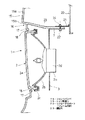
まず、本実施形態のランプであるフォグランプ1の概略構成を、図1を参照して説明すると、正面形状略方形のランプ本体2と、このランプ本体2の後部に配設されてランプ本体2を上下揺動可能に支持する略方形枠板状のランプブラケット3にて構成されている。ランプブラケット3の中央には、ランプ本体2の後部が貫通する開口3aが形成され、両側縁の上端部及び下端部から前方に取付片4a〜4dが延出されている。取付片4a〜4dの先端には外方にL字状に取付部5が屈曲形成され、取付穴6が形成されている。また、ランプブラケット3の上縁の略中央部から後方に固定片7が延出され、ボルト穴8が形成されている。
【0012】
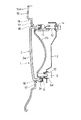
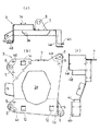
ランプ本体2は、図2に示すように、ランプレンズ2aとランプユニット2bをシール材2cを介して一体接合して構成されており、ランプユニット2bの中央の後方突出部2dが開口3aを貫通している。また、図3に示すように、ランプユニット2bの下端部の両側には、後方に向けて先端に球状軸支部9aを形成した枢支突部9が突設され、上端部の一側にはエイミングスクリュー機構10の結合片11が配設されている。
【0013】
ランプブラケット3の下端部両側には、図3、図4に示すように、枢支突部9に対応して方形装着穴12が形成され、球状軸支部9aを回転自在に支持する軸受部材13が嵌着固定されている。また、ランプブラケット3の上端部一側には、結合片11に対応して方形装着穴14が形成され、エイミングスクリュー機構10が装着されている。かくして、エイミングスクリュー機構10を後方から回転操作してランプブラケット3とランプ本体2の上端部を接近離間動作させることによりランプ本体2は下端部の軸受部材13を中心にして前後に揺動する。この前後揺動はランプ本体2の水平軸芯まわりの上下揺動でもあり、ランプ本体2の光軸の上下調整を行うことができる。
【0014】
以上の構成のフォグランプ1が、図2、図3に示すように、フロントバンパ15に配設されている。フロントバンパ15のフォグランプ配設部16は、フロントバンパ15の意匠面15aから若干凹入形成されており、その底面に周縁枠17を残してランプ本体2の前部のランプレンズ2aが適当な微小隙間をあけて丁度嵌合するランプ配置穴18が形成されている。ランプレンズ2aとランプ配置穴18の間の微小隙間は、フォグランプ1の取付公差を吸収しかつ光軸調整時のランプ本体2の前後揺動を許容する範囲で可及的に小さく設定されている。
【0015】
このようなフォグランプ1の配設状態は、ランプブラケット3の取付片4a〜4dの取付部5を、従来例と同様にフロントバンパ15の裏面に突設された取付ボス(図5の37参照)に当接させ、図1に示すように、取付穴6を貫通するタッピングねじからなる取付ビス19にて締結固定するとともに、図1、図2に示すように、ランプブラケット3の固定片7を車体側のフレーム部材であるラジエータサポート20に固着したナット部材24が設けられたブラケット21に固定ボルト22にて締結固定して実現されている。さらに、フロントバンパ15のフォグランプ配設部16から後方に向けて連結片23が延出され、この連結片23をブラケット21と固定片7の間に介在させた状態で固定ボルト22にて共締め状態で締結固定され、連結片23を介してフロントバンパ15のフォグランプ配設部16が車体側のフレーム部材に連結固定されている。なお、車体側フレーム部材には、ナット部材24の代わりにスタッドボルトを設けておき、固定ナットで締付固定してもよい。
【0016】
以上の構成において、ランプ本体2とランプブラケット3から成るフォグランプ1を車体側に取付ける際には、まずフォグランプ1をフロントバンパ15の後側に挿入してランプ本体2のランプレンズ2aをランプ配置穴18に嵌合配置するとともに、ランプブラケット3の位置を微調整して取付片4a〜4dをフロントバンパ15の取付ボスに取付ビス19にて固定する。その後フロントバンパ15を車体側に沿わせて、ブラケット21と連結片23と固定片7を固定ボルト22で締結固定し、さらに連結片23以外の取付部(図示せず)をボルトで締結固定することにより取付が完了する。
【0017】
このフォグランプ1の取付状態で、エイミングスクリュー機構10の回転操作によって、簡単にランプ本体2をランプブラケット3に対して上下揺動させて光軸を上下に調整できる。
【0018】
また、ランプブラケット3はフロントバンパ15の取付ボスに固定されるとともに固定片7が車体側フレーム部材であるラジエータサポート20に固定ボルト22にて締結固定されていることによってフォグランプ1を高い取付剛性をもって固定でき、走行振動によって光軸がぶれることがなくて適正に照明できる。
【0019】
また、フロントバンパ15から延出された連結片23が固定片7と共締めにて車体側フレーム部材であるラジエタータサポート20にブラケット21を介して固定されているので、組み付け工数を増加することなく、ランプブラケット3とその固定片7及び連結片23が相互にフロントバンパ15の剛性を高めるように作用し、フロントバンパ15の取付剛性が向上する。また、連結片23のボルト穴付近も、板金製の固定片7及びブラケット21で挟持され、剛性を向上させることができる。さらに、フロントバンパ15の連結片23は、板金製の固定片7を介して、ボルト22で締結固定されるので、ボルト22から連結片23(樹脂製)に加わる面圧を低く抑えることができ、ボルト22の緩みを防止できる。連結片23をフロントバンパ15の意匠面15aから凹入形成されたフランジ15bより延出形成したので、連結片23により意匠面15aにヒケが生じることはない。
【0020】
また、フォグランプ1自体もランプ本体2と板材の簡単なプレス加工にて作成できるランププラケット3にて構成されているので、低コストにて製造することができる。
【0021】
なお、上記実施形態の説明ではフォグランプの取付構造について説明したが、本発明はその他のランプの取付にも適用することができる。
【0022】
【発明の効果】
本発明の自動車のランプ取付構造によれば、以上のようにランプ本体をランプブラケットに対して上下揺動させて光軸を上下に調整でき、かつそのランプブラケットはフロントバンパの取付ボスに固定されるとともに固定片が車体側フレーム部材にボルトにて締結固定されているのでランプを高い取付剛性をもって固定でき、走行振動によって光軸がぶれることがなくて適正に照明でき、またフロントバンパのランプ配置穴の周辺部から延出された連結片が固定片と共締めにて車体側フレーム部材に固定されているので、組み付け工数を増加することなく、ランプブラケットとその固定片及び連結片が相互にフロントバンパの剛性を高めるように作用してフロントバンパの取付剛性が向上することができる。
【図面の簡単な説明】
【図1】本発明の自動車のランプ取付構造の一実施形態におけるランプの概略構成を示す斜視図である。
【図2】同実施形態におけるランプの中央位置での縦断側面図である。
【図3】同実施形態におけるランプの一側部での縦断側面図である。
【図4】同実施形態におけるランプブラケットを示し、(a)は平面図、(b)は正面図、(c)は側面図である。
【図5】従来例のフォグランプの取付構造の縦断側面図である。
【符号の説明】
1 フォグランプ
2 ランプ本体
3 ランプブラケット
7 固定片
15 フロントバンパ
18 ランプ配置穴
19 取付ビス
20 ラジエータサポート(フレーム部材)
22 固定ボルト
23 連結片[0001]
BACKGROUND OF THE INVENTION
The present invention relates to an automobile lamp mounting structure, and more particularly to a lamp mounting structure disposed in a lamp mounting hole formed in a front bumper.
[0002]
[Prior art]
Conventionally, fog lamps have been separately attached to the lower part of the front bumper as an accessory part. However, in recent years, the fog lamp may be standardized by being arranged in a lamp arrangement hole formed in the front bumper.
[0003]
When the fog lamp is attached separately, the optical axis is adjusted by mounting adjustment with the mounting bracket, but when it is installed in the front bumper, it is fixed to the front bumper so that the lamp itself is equipped with a vertical adjustment mechanism for the optical axis. It is necessary to use the lamp, and it is very expensive to use a lamp having a configuration in which the position of the bulb is adjusted with respect to the reflecting mirror and the lamp lens like the headlamp.
[0004]
Therefore, as shown in FIG. 5, a lamp formed on a
[0005]
In Japanese Utility Model Laid-Open No. 4-99145, a lamp is disposed on a resin front bumper, and a clip provided on the lamp is engaged and fixed to a rib formed on the front bumper and extends backward from the lamp. The thing which fastened and fixed the taken-out mounting bracket to the frame member by the side of a vehicle body with the volt | bolt is disclosed.
[0006]
[Problems to be solved by the invention]
However, in the configuration shown in FIG. 5, when the
[0007]
Further, what is disclosed in Japanese Utility Model Laid-Open No. 4-99145 is an integrated lamp, so that the optical axis cannot be adjusted, and the mounting bracket is extended and fixed to the frame member on the vehicle body side. However, since the ramp and the front bumper are only engaged with the clip, the mounting bracket cannot increase the rigidity of the front bumper.If the weight of the ramp is heavy, the same problem occurs. In order to increase the rigidity, it is necessary to extend a separately provided stay and fix it to the frame member, which causes a problem that the number of assembling steps increases.
[0008]
In view of the above-described conventional problems, the present invention can adjust the optical axis of the lamp, and the front bumper is insufficiently rigid so that the optical axis does not shake due to running vibration and can be properly illuminated, and the mounting rigidity of the front bumper Another object of the present invention is to provide an automobile lamp mounting structure that can be improved.
[0009]
[Means for Solving the Problems]
The automobile lamp mounting structure of the present invention is provided with a lamp formed by supporting the lamp body by a lamp bracket so as to be swingable up and down, and the lamp body is disposed in a lamp placement hole formed so as to penetrate the front bumper. In this state, fix the appropriate part of the lamp bracket to the mounting boss projecting on the back of the front bumper with a screw and fix it from the periphery of the fixing piece that extends backward from the lamp bracket and the lamp placement hole of the front bumper. The connecting piece extending rearward is fastened to the frame member on the vehicle body with bolts, and the optical axis can be adjusted up and down by swinging the lamp body up and down relative to the lamp bracket. The lamp bracket is fixed to the mounting boss of the front bumper and the fixed piece is fastened and fixed to the vehicle body side frame member with a bolt. The can be fixed with high mounting rigidity, it can properly illuminated without optical axis blurred by the traveling vibration and body connection piece extending from the periphery of the lamp mounting holes of the front bumper at a fixed piece and tightened Because it is fixed to the side frame member, the mounting rigidity of the front bumper can be improved by increasing the rigidity of the front bumper with the lamp bracket and its fixed piece and connecting piece without increasing the number of assembly steps. Can do.
[0010]
DETAILED DESCRIPTION OF THE INVENTION
Hereinafter, an embodiment of an automobile lamp mounting structure of the present invention will be described with reference to FIGS.
[0011]
First, a schematic configuration of a
[0012]
As shown in FIG. 2, the
[0013]
As shown in FIGS. 3 and 4,
[0014]
The
[0015]
The
[0016]
In the above configuration, when the
[0017]
With the
[0018]
Further, the
[0019]
Further, since the connecting
[0020]
Further, since the
[0021]
In the above description of the embodiment, the fog lamp mounting structure has been described, but the present invention can also be applied to mounting of other lamps.
[0022]
【The invention's effect】
According to the automobile lamp mounting structure of the present invention, the lamp body can be swung up and down with respect to the lamp bracket as described above to adjust the optical axis up and down, and the lamp bracket is fixed to the mounting boss of the front bumper. In addition, the fixing piece is fastened and fixed to the vehicle body side frame member with bolts, so that the lamp can be fixed with high mounting rigidity, the light axis does not shake due to running vibration, and the lamp can be properly illuminated. Since the connecting piece extending from the periphery of the hole is fixed to the vehicle body side frame member by fastening together with the fixing piece, the lamp bracket and the fixing piece and the connecting piece can be mutually connected without increasing the number of assembling steps. The mounting rigidity of the front bumper can be improved by acting to increase the rigidity of the front bumper.
[Brief description of the drawings]
FIG. 1 is a perspective view showing a schematic configuration of a lamp in an embodiment of a lamp mounting structure for an automobile of the present invention.
FIG. 2 is a longitudinal side view of the lamp at the center position in the same embodiment.
FIG. 3 is a longitudinal side view of one side portion of the lamp in the embodiment.
4A and 4B show a lamp bracket according to the embodiment, where FIG. 4A is a plan view, FIG. 4B is a front view, and FIG. 4C is a side view.
FIG. 5 is a vertical side view of a conventional fog lamp mounting structure.
[Explanation of symbols]
DESCRIPTION OF
22
Claims (1)
Priority Applications (1)
| Application Number | Priority Date | Filing Date | Title |
|---|---|---|---|
| JP34881698A JP3673418B2 (en) | 1998-12-08 | 1998-12-08 | Car lamp mounting structure |
Applications Claiming Priority (1)
| Application Number | Priority Date | Filing Date | Title |
|---|---|---|---|
| JP34881698A JP3673418B2 (en) | 1998-12-08 | 1998-12-08 | Car lamp mounting structure |
Publications (2)
| Publication Number | Publication Date |
|---|---|
| JP2000168433A JP2000168433A (en) | 2000-06-20 |
| JP3673418B2 true JP3673418B2 (en) | 2005-07-20 |
Family
ID=18399572
Family Applications (1)
| Application Number | Title | Priority Date | Filing Date |
|---|---|---|---|
| JP34881698A Expired - Fee Related JP3673418B2 (en) | 1998-12-08 | 1998-12-08 | Car lamp mounting structure |
Country Status (1)
| Country | Link |
|---|---|
| JP (1) | JP3673418B2 (en) |
Families Citing this family (3)
| Publication number | Priority date | Publication date | Assignee | Title |
|---|---|---|---|---|
| DE10336362B4 (en) * | 2003-08-08 | 2008-07-31 | GM Global Technology Operations, Inc., Detroit | Device for positioning two trim parts, in particular a headlight and a bumper, on a motor vehicle body |
| JP6273514B2 (en) * | 2014-03-28 | 2018-02-07 | ダイハツ工業株式会社 | Fog lamp mounting structure |
| EP4341606B1 (en) | 2021-05-19 | 2025-09-10 | HELLA GmbH & Co. KGaA | Vehicle lighting device comprising a support frame and manufacturing method |
-
1998
- 1998-12-08 JP JP34881698A patent/JP3673418B2/en not_active Expired - Fee Related
Also Published As
| Publication number | Publication date |
|---|---|
| JP2000168433A (en) | 2000-06-20 |
Similar Documents
| Publication | Publication Date | Title |
|---|---|---|
| US4306276A (en) | Motor vehicle flashing lamp and headlamp fixture | |
| JP2005112171A (en) | Front body structure of automobile | |
| SK972000A3 (en) | Preassembled frontal assembly for vehicles | |
| JP3820423B2 (en) | Mounting structure for vehicle lamp | |
| JP3673418B2 (en) | Car lamp mounting structure | |
| JP3319633B2 (en) | Scooter type motorcycle storage box | |
| JP3636906B2 (en) | Car lamp mounting structure | |
| US4325105A (en) | Headlight assembly | |
| JP3288871B2 (en) | Vehicle headlights | |
| JP4406856B2 (en) | Headlamp mounting structure | |
| JP3676009B2 (en) | Vehicle radiator mounting mechanism | |
| JP4230010B2 (en) | Headlamp mounting structure | |
| JP4140137B2 (en) | Instrument panel mounting device for motorcycles | |
| JP3336003B2 (en) | Vehicle tail lamp device | |
| RU2108253C1 (en) | Vehicle front part with headlight attachment device | |
| JPH0448992Y2 (en) | ||
| JPS601441Y2 (en) | Automotive combination lamp | |
| JP2577678Y2 (en) | License plate mounting structure | |
| JPS634709Y2 (en) | ||
| JPS5813526Y2 (en) | automotive headlights | |
| JPH10226374A (en) | Scooter type motorcycle | |
| JP2002079877A (en) | Front module for vehicle | |
| JP2780352B2 (en) | Mounting structure of auxiliary lights for automobiles | |
| JP3981438B2 (en) | Car lamp mounting structure | |
| JPH08324460A (en) | Vehicle hood support structure |
Legal Events
| Date | Code | Title | Description |
|---|---|---|---|
| A977 | Report on retrieval |
Free format text: JAPANESE INTERMEDIATE CODE: A971007 Effective date: 20040219 |
|
| A131 | Notification of reasons for refusal |
Free format text: JAPANESE INTERMEDIATE CODE: A131 Effective date: 20040224 |
|
| A521 | Written amendment |
Free format text: JAPANESE INTERMEDIATE CODE: A523 Effective date: 20040426 |
|
| A02 | Decision of refusal |
Free format text: JAPANESE INTERMEDIATE CODE: A02 Effective date: 20041109 |
|
| A521 | Written amendment |
Free format text: JAPANESE INTERMEDIATE CODE: A523 Effective date: 20041220 |
|
| A911 | Transfer of reconsideration by examiner before appeal (zenchi) |
Free format text: JAPANESE INTERMEDIATE CODE: A911 Effective date: 20050124 |
|
| TRDD | Decision of grant or rejection written | ||
| A01 | Written decision to grant a patent or to grant a registration (utility model) |
Free format text: JAPANESE INTERMEDIATE CODE: A01 Effective date: 20050412 |
|
| A61 | First payment of annual fees (during grant procedure) |
Free format text: JAPANESE INTERMEDIATE CODE: A61 Effective date: 20050422 |
|
| R150 | Certificate of patent (=grant) or registration of utility model |
Free format text: JAPANESE INTERMEDIATE CODE: R150 |
|
| FPAY | Renewal fee payment (prs date is renewal date of database) |
Free format text: PAYMENT UNTIL: 20080428 Year of fee payment: 3 |
|
| FPAY | Renewal fee payment (prs date is renewal date of database) |
Free format text: PAYMENT UNTIL: 20100428 Year of fee payment: 5 |
|
| FPAY | Renewal fee payment (prs date is renewal date of database) |
Free format text: PAYMENT UNTIL: 20100428 Year of fee payment: 5 |
|
| FPAY | Renewal fee payment (prs date is renewal date of database) |
Free format text: PAYMENT UNTIL: 20120428 Year of fee payment: 7 |
|
| LAPS | Cancellation because of no payment of annual fees |