JP3670608B2 - Cabin lifting device for work machines - Google Patents
Cabin lifting device for work machines Download PDFInfo
- Publication number
- JP3670608B2 JP3670608B2 JP2001379622A JP2001379622A JP3670608B2 JP 3670608 B2 JP3670608 B2 JP 3670608B2 JP 2001379622 A JP2001379622 A JP 2001379622A JP 2001379622 A JP2001379622 A JP 2001379622A JP 3670608 B2 JP3670608 B2 JP 3670608B2
- Authority
- JP
- Japan
- Prior art keywords
- cabin
- slide
- frame
- movable frame
- driving means
- Prior art date
- Legal status (The legal status is an assumption and is not a legal conclusion. Google has not performed a legal analysis and makes no representation as to the accuracy of the status listed.)
- Expired - Fee Related
Links
Images


Classifications
-
- E—FIXED CONSTRUCTIONS
- E02—HYDRAULIC ENGINEERING; FOUNDATIONS; SOIL SHIFTING
- E02F—DREDGING; SOIL-SHIFTING
- E02F9/00—Component parts of dredgers or soil-shifting machines, not restricted to one of the kinds covered by groups E02F3/00 - E02F7/00
- E02F9/16—Cabins, platforms, or the like, for drivers
- E02F9/166—Cabins, platforms, or the like, for drivers movable, tiltable or pivoting, e.g. movable seats, dampening arrangements of cabins
Description
【0001】
【発明の属する技術分野】
本発明は油圧ショベルや破砕機、クレーン等の作業機械において、作業状況等に応じてキャビンを昇降させるキャビン昇降装置に関するものである。
【0002】
【従来の技術】
従来、この種のキャビン昇降装置として、
(I) 特開平10−88618号に示されているように、機械の本体フレームとキャビン背面との間に平行リンク機構を設け、この平行リンク機構を油圧シリンダで上下方向に回動させてキャビンを昇降させるもの、
(II) 特開平8−326101号に示されているように、ベースフレームとキャビン底面との間にX形に組まれたパンタグラフ式のリンク機構を油圧シリンダで上下方向に伸縮させてキャビンを昇降させるもの
が公知である。
【0003】
【発明が解決しようとする課題】
ところが、いずれの公知技術によっても、平行リンク運動のみ、またはパンタグラフの伸縮運動のみによってキャビンを昇降させるため、昇降ストロークを大きくとることができず、上昇位置でのキャビン高さが不足する。
【0004】
一方、この点の対策として、
(イ)下降位置でのキャビン高さを高く設定して上昇位置での高さを稼ぐ方法、
(ロ)リンク長を長くし、昇降ストロークを増やす方法、
が考えられる。
【0005】
しかし、上記(イ)の方法によると、下降位置でのキャビンへの乗り降りに不便となり、かつ、公道輸送時の車高制限を受けることから限界がある。
【0006】
また、上記(ロ)の方法によると、平行リンク方式の場合、油圧ショベルのような旋回式作業機械において、下降位置でキャビンが前方にせり出してオーバーハング量(旋回中心からの距離)が大きくなり、旋回半径が大きくなる上に、リンク連結部分のガタが増幅されてキャビンの揺れが大きくなる(居住性が悪くなる)。
【0007】
一方、パンタグラフ方式においても、下降位置での昇降装置の前後方向の占有スペースが大きくなり過ぎるとともに、平行リンク方式と同様に上昇位置でのキャビンの揺れが大きくなる等の弊害が生じる。
【0008】
このような事情から、公知技術によると、上昇位置でのオペレータの視点高さが低くなり、視界を十分に広げることができなかった。
【0009】
そこで本発明は、昇降ストロークを大きくしてキャビン上昇位置での視点を高くでき、しかもオペレータの乗降性の悪化や、旋回式作業機械における旋回半径の増加、キャビンの揺れ等の弊害を招かない作業機械のキャビン昇降装置を提供するものである。
【0010】
【課題を解決するための手段】
請求項1の発明は、キャビン後方の本体フレーム上に立設された固定フレームと、この固定フレームに上下スライド自在に係合された可動フレームと、この可動フレームをスライドさせるスライド駆動手段とによって上下運動を行うスライド機構が構成され、このスライド機構の可動フレームとキャビンとの間に、回動駆動手段により駆動されて上下方向の回動運動を行う四節リンク機構が設けられ、この四節リンク機構は第1及び第2両リンクを備え、この両リンクの上端部が上記可動フレームの上端部に、下端部がキャビン背面側の下端部にそれぞれピン連結されてなるものである。
【0011】
請求項2の発明は、請求項1の構成において、固定フレームと可動フレームの一方の左右両側にスライドブロック、他方の左右両側にこのスライドブロックにスライド自在に貫挿されたスライドレールがそれぞれ取付けられてスライド機構が構成され、かつ、固定、可動両フレームの左右方向の中央部間にスライド駆動手段としての油圧シリンダが取付けられたものである。
【0012】
請求項3の発明は、請求項1または2の構成において、四節リンク機構が、平行に配置された第1及び第2両リンクを有する平行リンク機構として構成され、上記第1及び第2両リンク間に回動駆動手段としての油圧シリンダが設けられたものである。
【0013】
請求項4の発明は、請求項1乃至3のいずれかの構成において、キャビンを水平軸を中心として上下方向に傾動させる傾動機構が設けられたものである。
【0014】
請求項5の発明は、請求項1乃至4のいずれかの構成において、キャビンを前後方向に移動させる前後移動機構が設けられたものである。
【0015】
上記構成によると、スライド機構の上下スライド運動と、四節リンク機構の回動運動の二種類の運動によってキャビンを昇降させるため、昇降ストロークを大きくとることができる。このため、上昇位置での視点を高くして視界を広げることができる。
【0016】
また、昇降ストロークを拡大できることで下降位置を低位置に設定することが可能となるため、オペレータの乗降に便利かつ安全となるとともに、キャビン下降状態での車高を低くして機械の公道輸送に有利となる。
【0017】
さらに、四節リンク機構(請求項3では平行リンク機構)のリンク長を短くできるため、下降位置でのキャビンのオーバーハングを小さくして旋回半径を小さくできるとともに、リンク長を短縮できることによりリンクのガタを小さくしてキャビンの揺れを抑え、居住性を改善することができる。
【0018】
この場合、本体フレーム上に立設された固定フレームに可動フレームをスライド自在に係合させてスライド機構を構成し、このスライド機構の可動フレームとキャビンとの間に四節リンク機構を設けているため、これとは逆に本体フレームに支柱を立ててこの支柱とキャビンとの間に四節リンク機構を設け、この四節リンク機構の先端部とキャビンとの間に上記同様のスライド機構を設けた場合と比較して、装置全体を小形・軽量にすることができる。
【0019】
また、請求項2の構成によると、可動フレームを固定フレームに対して左右両側でスライドレールとスライドブロックによって支持するため、中央部のみで支持する場合と比較してキャビンを安定良く支持し、左右の揺れを防止することができる。
【0020】
請求項3の構成によると、四節リンクとして平行リンク機構を用いているため、キャビンを水平姿勢のまま平行移動させることができる。
【0021】
請求項4の構成によると、キャビンを上下方向に傾動させることができるため、たとえばクレーン作業や解体作業のような前上方の作業時に、キャビンを上昇させたうえで、さらに上方作業点を見易いようにキャビンを上向きにする等、作業状況に応じてキャビンの俯仰角度を調節することが可能となる。
【0022】
一方、請求項5の構成によると、キャビンを前後移動させることができるため、作業点がグランドレベルよりも低い低所作業時にオペレータの視点を作業点を見易い前方に移動させることができる。また、キャビンを傾動させる請求項4の構成と組み合わせ、キャビンを前進させた上に下向きに傾ければ、より一層低所作業に便利となる。
【0023】
【発明の実施の形態】
第1実施形態(図1〜図3参照)
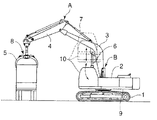
図1に、第1実施形態にかかる昇降装置を備えた作業機械としての廃材処理用のスクラップローダを示している。
【0024】
同図において、1はクローラ式の下部走行体で、この下部走行体1上に上部旋回体2が搭載され、この上部旋回体2に、ブーム3、アーム4、開閉式のクランプ5、それにブーム3を起伏させるブームシリンダ6、アーム4を水平軸まわりに回動させるアームシリンダ7、クランプ5を開閉させるクランプシリンダ8等から成る作業アタッチメントAが取付けられてスクラップローダが構成されている。
【0025】
上部旋回体2は本体フレームとしてのアッパフレーム9を有し、このアッパフレーム9にキャビン10が、昇降装置Bによって、図中実線で示す下降位置と、破線で示す上昇位置との間で昇降移動し得る状態で取付けられている。図中、二点鎖線は上記下降位置と上昇位置の中間のキャビン位置を示す。
【0026】
昇降装置Bの構成を図2,3によって説明する。
【0027】
この昇降装置Bは、キャビン10を上下にスライド移動させるスライド機構B1と、キャビン10を上下方向に回動移動させる四節リンク機構としての平行リンク機構B2とから成っている。
【0028】
スライド機構B1は、キャビン後方のアッパフレーム9上に立設された固定フレーム11と、この固定フレーム11にスライド自在に係合された可動フレーム12とを具備している。
【0029】
この固定、可動両フレーム11,12は、キャビン幅に近い幅寸法を有し、図3に示すように固定フレーム11の左右両側に上下に連続する凹部11a,11a、可動フレーム12の左右両側にこの凹部11a,11aに係合する凸部12a,12aがそれぞれ設けられている。
【0030】
また、この左右の凹凸係合部分において、固定フレーム11の上下複数個所(たとえば二個所)にスライドブロック13、可動フレーム12にこのスライドブロック13に図示しないボールベアリングを介してスライド自在に貫挿されたスライドレール14がそれぞれ設けられ、上記凹凸係合部分とこのスライドレール機構によって可動フレーム12が固定フレーム11に沿って上下にスライドする。
【0031】
15はスライド駆動手段としてのスライド用油圧シリンダ(以下、スライドシリンダという)で、両フレーム11,12の左右方向中央部においてチューブ端(下端)が固定フレーム11の下端部に、ロッド端(上端)が可動フレーム12の上端部にそれぞれ取付けられ、このスライドシリンダ15の伸縮作動によって可動フレーム12が上下にスライド駆動される。
【0032】
この可動フレーム12の前面左右両側には、後側リンクブラケット16,16が設けられ、この後側リンクブラケット16,16と、キャビン下側のデッキフレーム10aの後端部に設けられた前側リンクブラケット17,17との間に平行リンク機構B2が設けられている。
【0033】
この平行リンク機構B2は、キャビン下降状態で前側となる第1リンク18と、後側となる第2リンク19が平行に配置され、この両リンク18,19の上端部が後側リンクブラケット16,16に、下端部が前側リンクブラケット17,17にそれぞれ水平ピン20,21によって回動可能に連結されている。
【0034】
両リンク18,19はそれぞれ偏平な箱状に形成され、これらの左右方向の中央部間に回動駆動手段としての回動用油圧シリンダ(以下、回動シリンダという)22が設けられている。
【0035】
この回動シリンダ22は、ロッド端が第1リンク18に、チューブ端が可動フレーム12にそれぞれ水平ピン23,24によって回動可能に連結されている。
【0036】
平行リンク機構B2は、回動シリンダ22の縮小時には図2実線で示すように前下がりの傾斜姿勢となり、同シリンダ22が伸長作動したときに、前上方に回動して同二点鎖線及び破線で示す前上がりの傾斜姿勢となる。
【0037】
上記構成において、キャビン10内のオペレータの視点をとくに高くする必要のない通常作業時や公道走行時は、スライド、回動両シリンダ15,22が縮小されてキャビン10が下降位置にセットされる。
【0038】
一方、スクラップを上方に持ち上げて高所に置く作業時のようにオペレータの視点を高くしたいときは、スライド、回動両シリンダ15,22の一方または双方を伸長作動させる。
【0039】
たとえば回動シリンダ22を伸長作動させると、平行リンク機構B2が前上方に回動(平行移動)して、キャビン10が水平姿勢のまま図1,2実線の下降位置から同二点鎖線の中間位置まで上昇する。
【0040】
そして、この状態からさらにスライドシリンダ15を伸長作動させると、スライド機構B1が作動(可動フレーム12がスライド)して、キャビン10が中間位置から図1,2破線の上昇位置まで上昇する。
【0041】
このように、スライド機構B1の上下スライド運動と、平行リンク機構B2の回動運動の二種類の運動によってキャビン10を昇降させるため、キャビン10を大きなストロークで昇降させることができる。
【0042】
このため、キャビン10をリンク機構(平行リンク式またはパンタグラフ式)のみで昇降させる公知技術と比較して、上昇位置でのオペレータの視点を格段に高くして視界を大幅に広げることが可能となる。
【0043】
また、昇降ストロークを拡大できることでキャビン10の下降位置を低位置に設定することが可能となるため、オペレータの乗降に便利かつ安全となるとともに、キャビン下降状態での車高を低くして機械の公道輸送に有利となる。
【0044】
さらに、スライド機構B1の可動フレーム12を固定フレーム11に対して、互いの凹凸係合部分とスライドレール機構とによって左右両側で支持するため、中央部のみで係合支持する場合と比較してキャビン10を安定良く支持し、左右の揺れを防止することができる。
【0045】
第2及び第3実施形態
第1実施形態との相違点のみを説明する。
【0046】
図4に示す第2実施形態においては、スライド機構B1の固定フレーム11がアッパフレーム9に対し左右方向の水平軸25まわりに回動可能に取付けられ、同フレーム11とアッパフレーム9との間に設けられた傾動シリンダ(油圧シリンダ)26によって垂直姿勢から前傾または後傾姿勢に傾動するように構成されている。
【0047】
この構成によると、固定フレーム11の傾動運動によってキャビン10を水平姿勢から俯仰させることができるため、高所で荷を扱う作業時に、キャビン10を上昇させた上で上向きに傾けることにより、オペレータの視線を上向きに無理なく設定することができる。
【0048】
一方、図5に示す第3実施形態においては、キャビン10がデッキフレーム10aに対して前後移動可能に支持され、前後動シリンダ(油圧シリンダ)27によってキャビン10が前後移動するように構成されている。
【0049】
なお、10bはキャビン10の下面に取付けられたキャビン台で、前後動シリンダ27はデッキフレーム10aとこのキャビン台10bとの間に取付けられている。
【0050】
また、デッキフレーム10aとキャビン台10bとは、スライド機構B1に用いられたのと同じスライドブロック28とスライドレール29によってスライド自在に連結されている。
【0051】
この構成によると、グランドレベルよりも低い位置のスクラップを処理する場合のような低所作業時に、オペレータの視点を前方に移動させて作業点を見易くすることができる。
【0052】
なお、キャビン10を傾動させる第2実施形態と組み合わせ、キャビン10を前進させた上で下向きに傾ければ、より一層低所作業に便利となる。
【0053】
ところで、上記実施形態では、スライド機構B1及び平行リンク機構B2の駆動手段としてそれぞれ油圧シリンダ15,22を用いたが、これに代えて、電動機の回転力を直線運動に変換する機構(たとえばねじシリンダ)等を用いてもよい。
【0054】
また、上記実施形態では、四節リンク機構としてキャビン10を平行移動させる平行リンク機構を用いたが、キャビン10を必ずしも平行移動させる必要がない(非平行移動させても支障がない)場合には、第1及び第2両リンク18,19が非平行状態で配置された非平行リンク機構を用いてもよい。
【0055】
さらに、本発明は、上記実施形態で挙げたスクラップローダに限らず、油圧ショベルやクレーン、破砕機、深穴掘削機等、キャビンを備えた作業機械に広く適用することができる。
【0056】
【発明の効果】
上記のように本発明によると、スライド機構の上下スライド運動と、四節リンク機構の回動運動の二種類の運動によってキャビンを昇降させる構成としたから、リンク機構のみで昇降させる公知技術と比較してキャビンの昇降ストロークを拡大することができる。このため、上昇位置での視点を高くして視界を広げ、作業性を向上させることができる。
【0057】
また、昇降ストロークを拡大できることで下降位置を低位置に設定することが可能となるため、オペレータの乗降に便利となるとともに、キャビン下降状態での車高を低くして機械の公道輸送に有利となる。
【0058】
さらに、四節リンク機構(請求項3では平行リンク機構)のリンク長を短くできるため、下降位置でのキャビンのオーバーハングを小さくして旋回半径を小さくできるとともに、リンク長を短縮できることによりリンクのガタを小さくしてキャビンの揺れを抑え、居住性を良くすることができる。
【図面の簡単な説明】
【図1】 本発明の第1実施形態にかかる昇降装置が組み込まれたスクラップローダの全体概略側面図である。
【図2】 同実施形態におけるキャビンと昇降装置の拡大側面図である。
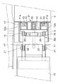
【図3】 同部分拡大平面図である。
【図4】 本発明の第2実施形態を示す図2相当図である。
【図5】 本発明の第3実施形態を示す図2相当図である。
【符号の説明】
9 機械の本体フレームとしてのアッパフレーム
10 キャビン
B 昇降装置
B1 スライド機構
11 スライド機構を構成する固定フレーム
12 同可動フレーム
13 スライドブロック
14 スライドレール
15 スライド駆動手段としての油圧シリンダ
B2 四節リンク機構としての平行リンク機構
18 平行リンク機構を構成する第1リンク
19 同第2リンク
22 回動駆動手段としての油圧シリンダ
25 キャビン傾動機構を構成する水平軸
26 同傾動シリンダ
10a キャビン前後移動機構を構成するデッキフレーム
10b 同キャビン台
27 同油圧シリンダ[0001]
BACKGROUND OF THE INVENTION
The present invention relates to a cabin elevating device that elevates and lowers a cabin according to a working situation or the like in a working machine such as a hydraulic excavator, a crusher, or a crane.
[0002]
[Prior art]
Conventionally, as this kind of cabin lifting device,
(I) As disclosed in Japanese Patent Laid-Open No. 10-88618, a parallel link mechanism is provided between the machine body frame and the back of the cabin, and the parallel link mechanism is turned up and down by a hydraulic cylinder to form a cabin. Things that raise and lower,
(II) As shown in Japanese Patent Laid-Open No. 8-326101, the pantograph-type link mechanism assembled in an X shape between the base frame and the bottom of the cabin is expanded and contracted vertically by a hydraulic cylinder to raise and lower the cabin. What is to be made is known.
[0003]
[Problems to be solved by the invention]
However, any known technique raises or lowers the cabin only by the parallel link motion or only the expansion and contraction motion of the pantograph, so that the lifting stroke cannot be made large and the cabin height at the raised position is insufficient.
[0004]
On the other hand, as measures against this point,
(B) A method of increasing the cabin height at the lowered position and increasing the height at the raised position,
(B) A method of increasing the link length and increasing the lifting stroke,
Can be considered.
[0005]
However, the method (b) is inconvenient for getting in and out of the cabin at the lowered position, and has a limit because it is subject to vehicle height restrictions during public road transportation.
[0006]
Also, according to the method (b) above, in the case of a parallel link system, in a swivel work machine such as a hydraulic excavator, the cabin protrudes forward at the lowered position and the overhang amount (distance from the swivel center) increases. In addition to an increase in the turning radius, the backlash at the link connecting portion is amplified, resulting in increased cabin shaking (comfortableness deteriorates).
[0007]
On the other hand, in the pantograph method, the occupied space in the front-rear direction of the lifting device at the lowered position becomes too large, and there are problems such as the cabin swinging at the raised position becoming larger as in the parallel link method.
[0008]
Under such circumstances, according to the known technique, the viewpoint height of the operator at the raised position is low, and the field of view cannot be sufficiently expanded.
[0009]
Therefore, the present invention can increase the lift stroke and raise the viewpoint at the cabin ascending position, and does not cause adverse effects such as deterioration of the operator's boarding / exiting property, increase of the turning radius in the swing type work machine, and shaking of the cabin. A cabin lifting device for a machine is provided.
[0010]
[Means for Solving the Problems]
According to the first aspect of the present invention, a fixed frame standing on a main body frame behind the cabin, a movable frame engaged with the fixed frame so as to be vertically slidable, and a slide driving means for sliding the movable frame, A slide mechanism that performs the movement is configured, and a four-bar link mechanism that is driven by a rotation driving unit to perform a vertical rotation movement is provided between the movable frame of the slide mechanism and the cabin. The mechanism includes both first and second links, and the upper ends of both links are pin-connected to the upper end of the movable frame and the lower ends are connected to the lower end of the cabin rear side .
[0011]
According to a second aspect of the present invention, in the configuration of the first aspect , a slide block is attached to each of the left and right sides of one of the fixed frame and the movable frame, and slide rails slidably inserted into the slide block are attached to the left and right sides of the other. Te slide mechanism is constituted, and fixed, in which a hydraulic cylinder as a sliding drive means between the central portions of the right and left direction of the movable both frames is kicked attached.
[0012]
According to a third aspect of the present invention, in the configuration of the first or second aspect, the four-bar link mechanism is configured as a parallel link mechanism having both first and second links arranged in parallel. hydraulic cylinder as a rotation driving means is one that was kicked set between links.
[0013]
According to a fourth aspect of the present invention, there is provided a tilting mechanism for tilting the cabin in the vertical direction about the horizontal axis in any one of the first to third aspects.
[0014]
According to a fifth aspect of the present invention, there is provided a back-and-forth movement mechanism for moving the cabin in the front-rear direction .
[0015]
According to the above configuration, since the cabin is moved up and down by two types of movements, that is, the vertical sliding movement of the sliding mechanism and the rotational movement of the four-bar linkage mechanism, the lifting stroke can be increased. For this reason, it is possible to widen the field of view by increasing the viewpoint at the raised position.
[0016]
In addition, the lowering position can be set to a lower position by expanding the lifting stroke, making it convenient and safe for operators to get on and off, and lowering the vehicle height when the cabin is lowered to transport public roads on machinery. It will be advantageous.
[0017]
Furthermore, since the link length of the four-bar linkage mechanism (parallel link mechanism in claim 3 ) can be shortened, the overhang of the cabin at the lowered position can be reduced to reduce the turning radius, and the link length can be shortened. The backlash can be reduced to reduce cabin shaking and improve comfort.
[0018]
In this case, the fixed frame in a movable frame that are disposed on the body frame slidably engaged to constitute a slide mechanism, provided with a four-bar linkage mechanism between the movable frame and the cabin of the slide mechanism Contrary to this, a column is set up on the main body frame, and a four-bar linkage mechanism is provided between the column and the cabin. A slide mechanism similar to the above is provided between the tip of the four-bar link mechanism and the cabin. Compared with the case where it is provided, the entire apparatus can be reduced in size and weight.
[0019]
Further, according to the configuration of the second aspect , since the movable frame is supported by the slide rail and the slide block on both the left and right sides with respect to the fixed frame, the cabin is supported more stably than the case where the movable frame is supported only at the center portion. Can be prevented.
[0020]
According to the configuration of the third aspect, since the parallel link mechanism is used as the four-bar link, the cabin can be translated in a horizontal posture.
[0021]
According to the fourth aspect of the present invention, the cabin can be tilted in the vertical direction, so that the upper working point can be more easily seen after raising the cabin during the front upper work such as crane work or dismantling work. It is possible to adjust the elevation angle of the cabin according to the work situation, for example, with the cabin facing upward.
[0022]
On the other hand, since the cabin can be moved back and forth according to the configuration of the fifth aspect , the operator's viewpoint can be moved forward so that the work point can be easily seen when working at a low place where the work point is lower than the ground level. Further, in combination with the structure of the fourth aspect in which the cabin is tilted, if the cabin is moved forward and tilted downward, it becomes more convenient for work in a low place.
[0023]
DETAILED DESCRIPTION OF THE INVENTION
1st Embodiment (refer FIGS. 1-3)
FIG. 1 shows a scrap loader for waste material processing as a work machine provided with a lifting device according to the first embodiment.
[0024]
In the figure, reference numeral 1 denotes a crawler type lower traveling body, and an upper revolving
[0025]
The
[0026]
The configuration of the lifting device B will be described with reference to FIGS.
[0027]
The lifting device B includes a slide mechanism B1 that slides the
[0028]
The slide mechanism B <b> 1 includes a fixed
[0029]
Both the fixed and
[0030]
Further, in the left and right concave and convex engaging portions, the
[0031]
[0032]
[0033]
In the parallel link mechanism B2, the
[0034]
Both
[0035]
The rotating
[0036]
When the
[0037]
In the above-described configuration, during normal work or public road travel where the operator's viewpoint in the
[0038]
On the other hand, when it is desired to raise the viewpoint of the operator as in the operation of lifting the scrap upward and placing it at a high place, one or both of the slide and
[0039]
For example, when the
[0040]
When the
[0041]
Thus, since the
[0042]
For this reason, compared with the known technique which raises / lowers the
[0043]
In addition, since the lifting / lowering stroke can be enlarged, the lowering position of the
[0044]
Further, since the
[0045]
Second and Third Embodiments Only differences from the first embodiment will be described.
[0046]
In the second embodiment shown in FIG. 4, the fixed
[0047]
According to this configuration, since the
[0048]
On the other hand, in the third embodiment shown in FIG. 5, the
[0049]
[0050]
Further, the
[0051]
According to this configuration, it is possible to move the operator's viewpoint forward to make it easier to see the work point when working in a low place such as when processing scrap at a position lower than the ground level.
[0052]
In combination with the second embodiment in which the
[0053]
In the above embodiment, the
[0054]
In the above embodiment, the parallel link mechanism that translates the
[0055]
Furthermore, the present invention is not limited to the scrap loader described in the above embodiment, and can be widely applied to work machines having a cabin such as a hydraulic excavator, a crane, a crusher, and a deep hole excavator.
[0056]
【The invention's effect】
As described above, according to the present invention, the cabin is moved up and down by two types of movements, that is, the vertical sliding movement of the sliding mechanism and the rotational movement of the four-bar linkage mechanism. Thus, the lifting / lowering stroke of the cabin can be expanded. For this reason, it is possible to increase the viewpoint at the raised position, widen the field of view, and improve workability.
[0057]
In addition, since the lowering position can be set to a low position by expanding the lifting stroke, it is convenient for operators to get on and off, and it is advantageous for transporting machinery on public roads by lowering the vehicle height when the cabin is lowered. Become.
[0058]
Furthermore, since the link length of the four-bar linkage mechanism (parallel link mechanism in claim 3 ) can be shortened, the overhang of the cabin at the lowered position can be reduced to reduce the turning radius, and the link length can be shortened. By reducing the backlash, the cabin can be prevented from shaking and the comfort can be improved.
[Brief description of the drawings]
FIG. 1 is an overall schematic side view of a scrap loader incorporating a lifting device according to a first embodiment of the present invention.
FIG. 2 is an enlarged side view of the cabin and the lifting device in the same embodiment.
FIG. 3 is an enlarged plan view of the same part.
FIG. 4 is a view corresponding to FIG. 2 showing a second embodiment of the present invention.
FIG. 5 is a view corresponding to FIG. 2 showing a third embodiment of the present invention.
[Explanation of symbols]
9 Upper frame as
Claims (5)
Priority Applications (1)
| Application Number | Priority Date | Filing Date | Title |
|---|---|---|---|
| JP2001379622A JP3670608B2 (en) | 2001-12-13 | 2001-12-13 | Cabin lifting device for work machines |
Applications Claiming Priority (1)
| Application Number | Priority Date | Filing Date | Title |
|---|---|---|---|
| JP2001379622A JP3670608B2 (en) | 2001-12-13 | 2001-12-13 | Cabin lifting device for work machines |
Publications (2)
| Publication Number | Publication Date |
|---|---|
| JP2003184127A JP2003184127A (en) | 2003-07-03 |
| JP3670608B2 true JP3670608B2 (en) | 2005-07-13 |
Family
ID=27591093
Family Applications (1)
| Application Number | Title | Priority Date | Filing Date |
|---|---|---|---|
| JP2001379622A Expired - Fee Related JP3670608B2 (en) | 2001-12-13 | 2001-12-13 | Cabin lifting device for work machines |
Country Status (1)
| Country | Link |
|---|---|
| JP (1) | JP3670608B2 (en) |
Families Citing this family (2)
| Publication number | Priority date | Publication date | Assignee | Title |
|---|---|---|---|---|
| JP2011523924A (en) * | 2008-05-29 | 2011-08-25 | ボルボ コンストラクション イクイップメント アーベー | Pipe laying machine with cab lifting device |
| CN115162452B (en) * | 2022-07-22 | 2023-12-12 | 广西柳工机械股份有限公司 | Holding fork |
-
2001
- 2001-12-13 JP JP2001379622A patent/JP3670608B2/en not_active Expired - Fee Related
Also Published As
| Publication number | Publication date |
|---|---|
| JP2003184127A (en) | 2003-07-03 |
Similar Documents
| Publication | Publication Date | Title |
|---|---|---|
| US6616398B2 (en) | Lift boom assembly | |
| KR20070059988A (en) | Work vehicle and skid steer roader | |
| AU5653600A (en) | Retractable counterweight for straight-boom aerial work platform | |
| GB2392431A (en) | Rotatable and telescopic work machine | |
| WO2009064687A1 (en) | Tilt device for a material handling machine | |
| US6609587B1 (en) | Frame assembly for a work machine | |
| US4217971A (en) | Rotating powered step | |
| JP3670608B2 (en) | Cabin lifting device for work machines | |
| EP0474210A1 (en) | Vertical lift loader boom | |
| US6343799B1 (en) | Tilt mechanism for work machine | |
| JP3436659B2 (en) | Slope work vehicle | |
| JP3540806B2 (en) | Construction equipment with cab | |
| JP4190811B2 (en) | Aerial work platform | |
| JP4199737B2 (en) | Backhoe with transport means | |
| JP4456047B2 (en) | Horizontal pulling device for railroad work machine | |
| JP4354440B2 (en) | Crawler work vehicle | |
| JP4022503B2 (en) | Forklift equipment | |
| JP3043964B2 (en) | Reader support device | |
| JP4000975B2 (en) | Self-propelled working machine | |
| CN212105727U (en) | Anchor rod drill carriage | |
| JP3948654B2 (en) | Construction machinery | |
| JPH0585789U (en) | Movable counterweight device | |
| JPH0788784A (en) | Robot work vehicle | |
| JPH0730402Y2 (en) | Track work machine | |
| JP5476188B2 (en) | Work machine |
Legal Events
| Date | Code | Title | Description |
|---|---|---|---|
| A977 | Report on retrieval |
Free format text: JAPANESE INTERMEDIATE CODE: A971007 Effective date: 20041203 |
|
| A131 | Notification of reasons for refusal |
Free format text: JAPANESE INTERMEDIATE CODE: A131 Effective date: 20041214 |
|
| A521 | Written amendment |
Free format text: JAPANESE INTERMEDIATE CODE: A523 Effective date: 20050214 |
|
| TRDD | Decision of grant or rejection written | ||
| A01 | Written decision to grant a patent or to grant a registration (utility model) |
Free format text: JAPANESE INTERMEDIATE CODE: A01 Effective date: 20050405 |
|
| A61 | First payment of annual fees (during grant procedure) |
Free format text: JAPANESE INTERMEDIATE CODE: A61 Effective date: 20050414 |
|
| R150 | Certificate of patent or registration of utility model |
Ref document number: 3670608 Country of ref document: JP Free format text: JAPANESE INTERMEDIATE CODE: R150 Free format text: JAPANESE INTERMEDIATE CODE: R150 |
|
| FPAY | Renewal fee payment (event date is renewal date of database) |
Free format text: PAYMENT UNTIL: 20080422 Year of fee payment: 3 |
|
| FPAY | Renewal fee payment (event date is renewal date of database) |
Free format text: PAYMENT UNTIL: 20090422 Year of fee payment: 4 |
|
| FPAY | Renewal fee payment (event date is renewal date of database) |
Free format text: PAYMENT UNTIL: 20090422 Year of fee payment: 4 |
|
| FPAY | Renewal fee payment (event date is renewal date of database) |
Free format text: PAYMENT UNTIL: 20100422 Year of fee payment: 5 |
|
| FPAY | Renewal fee payment (event date is renewal date of database) |
Free format text: PAYMENT UNTIL: 20110422 Year of fee payment: 6 |
|
| FPAY | Renewal fee payment (event date is renewal date of database) |
Free format text: PAYMENT UNTIL: 20130422 Year of fee payment: 8 |
|
| FPAY | Renewal fee payment (event date is renewal date of database) |
Free format text: PAYMENT UNTIL: 20130422 Year of fee payment: 8 |
|
| FPAY | Renewal fee payment (event date is renewal date of database) |
Free format text: PAYMENT UNTIL: 20140422 Year of fee payment: 9 |
|
| LAPS | Cancellation because of no payment of annual fees |