JP3662374B2 - Cable car equipment - Google Patents
Cable car equipment Download PDFInfo
- Publication number
- JP3662374B2 JP3662374B2 JP30335396A JP30335396A JP3662374B2 JP 3662374 B2 JP3662374 B2 JP 3662374B2 JP 30335396 A JP30335396 A JP 30335396A JP 30335396 A JP30335396 A JP 30335396A JP 3662374 B2 JP3662374 B2 JP 3662374B2
- Authority
- JP
- Japan
- Prior art keywords
- tire
- traction
- cable
- cable car
- tires
- Prior art date
- Legal status (The legal status is an assumption and is not a legal conclusion. Google has not performed a legal analysis and makes no representation as to the accuracy of the status listed.)
- Expired - Lifetime
Links
Images


Classifications
-
- B—PERFORMING OPERATIONS; TRANSPORTING
- B61—RAILWAYS
- B61B—RAILWAY SYSTEMS; EQUIPMENT THEREFOR NOT OTHERWISE PROVIDED FOR
- B61B12/00—Component parts, details or accessories not provided for in groups B61B7/00 - B61B11/00
- B61B12/02—Suspension of the load; Guiding means, e.g. wheels; Attaching traction cables
- B61B12/022—Vehicle receiving and dispatching devices
-
- B—PERFORMING OPERATIONS; TRANSPORTING
- B61—RAILWAYS
- B61B—RAILWAY SYSTEMS; EQUIPMENT THEREFOR NOT OTHERWISE PROVIDED FOR
- B61B7/00—Rope railway systems with suspended flexible tracks
-
- B—PERFORMING OPERATIONS; TRANSPORTING
- B61—RAILWAYS
- B61B—RAILWAY SYSTEMS; EQUIPMENT THEREFOR NOT OTHERWISE PROVIDED FOR
- B61B12/00—Component parts, details or accessories not provided for in groups B61B7/00 - B61B11/00
- B61B12/10—Cable traction drives
- B61B12/105—Acceleration devices or deceleration devices other than braking devices
Abstract
Description
【0001】
【発明の属する技術の分野】
本発明は、2つのステーシヨン、とくに下方ステーシヨンおよび上方ステーシヨンを備え、少なくとも一つが駆動されている複数の変向円板上でステーシヨン内に案内される牽引ケーブルを備え、該牽引ケーブルに連結されるかまたはそれから連結解除され得るゴンドラまたは椅子のごとき多数の乗客搬送体を有し、前記ステーシヨンの領域に配置されるガイドレールを有し、該レールに沿って前記牽引ケーブルから連結解除された乗客搬送体が前記変向円板のまわりの連結解除領域から連結領域へ移動可能であり、そして前記ガイドレールに沿って動かされる乗客搬送体上に載置するようになる減速タイヤ、牽引タイヤおよび加速タイヤ群を有するケーブルカー装置に関する。
【0002】
【従来の技術】
この種の公知のケーブルカー装置においては、乗客搬送体を作動時間外に牽引ケーブルから連結解除しかつそれらのために設けられた部屋、いわゆるガレージに保管することが必要である。ステーシヨン建物に加えて、組み込まれかつ作動されねばならない建物がこのために設けられる。ステーシヨン建物の内部において、乗客搬送体用側線は、保管室に延びる接続レールが続く、ガイドレールと連係する。ケーブルカー装置が作動外に置かれると直ぐに、乗客搬送体は牽引ケーブルから連結解除されかつ側線および接続レールを経由して、それらがケーブルカー装置の作動時間外に保管されるガレージに送給される。これはとくに、乗客搬送体が作動時間外にケーブルカー装置の通路に沿ったままであるときに存在する要求、乗客搬送体から雪を掻き落とすような作動の再開に乗客搬送体を準備せねばならないことを不必要にする。
【0003】
しかしながら、この種の公知のケーブルカー装置においては、すべて乗客搬送体を保管するのに十分な空間を作りだす必要がある。この空間をケーブルカー装置の下方ステーシヨンに作るならば、その場合に幾らかの土地がそのために利用できなければならない。この場合には、追加の土地は常に利用可能とは限らず、仮に利用可能であったとしても、一般にコストが非常に増加する。逆に、上方ステーシヨンの領域にこの空間を作り出すことは追加の建物の建築およびその作動に極めて高いコストを必然的に伴う。
【0004】
【発明が解決しようとする課題】
従つて、本発明の目的は作動時間外に乗客搬送体を保管するのに必要とされる空間が最小にされ得るケーブルカー装置を創出することにある。本発明は乗客搬送体を保管するのにさらにステーシヨン建物内で利用し得る空間を使用する考えに基礎を置いている。この使用はそれ自体すでに提案されているけれども、しかしながら、支障としてはステーシヨン建物に配置された減速タイヤ、牽引タイヤおよび加速タイヤが同一の駆動装置を有するということである。乗客搬送体を保管するのにさらにステーシヨン建物を使用可能にするために、個々の駆動タイヤが個々に制御可能でなければならないが、これは非常に高いレベルの技術的努力を必要としかつ同時に非常に高いコストを伴う。
【0005】
かくして本発明は個々の駆動タイヤ群の作動モードが、ステーシヨン建物内で利用し得る空間が乗客搬送体を保管するのにも使用され得るように簡単な方法において制御可能であるケーブルカー装置を創出することを目的とする。
【0006】
【課題を解決するための手段】
本発明によれば、これは、減速タイヤ、牽引タイヤ、および/または加速タイヤの少なくとも幾つかが牽引ケーブルから連結解除される乗客搬送体に対して作動外に置かれることができ、その結果として前記乗客搬送体が、装置作動時間外に、これらのタイヤと連係されるガイドレールの領域に保管され得ることにより達成される。
【0007】
また、本発明は、減速タイヤおよび加速タイヤが上昇可能であり、その結果としてこれらのタイヤが前記乗客搬送体との係合から外され得る。前記減速タイヤまたは前記加速タイヤが復帰力の作用に抗して、とくに復帰ばねの作用に抗して上昇可能である。また、とくに、前記減速タイヤまたは加速タイヤが油圧的に上昇可能である。そのうえ、好ましくは、前記上昇可能なタイヤに隣接する該タイヤの1つが駆動機構から連結解除されかつブレーキにより制御され得る。
【0008】
さらに他の好適な実施例において、クラツチが1群の牽引タイヤと連係し、そのクラツチによつてこれらのタイヤが駆動機構から接続解除され得、そして制動装置がまたこれらのタイヤと連係する。とくに、クラツチと制動装置が前記牽引タイヤの他のタイヤと連係する。
【0009】
ケーブルカー装置において乗客搬送体を保管するための好適な方法は、減速タイヤ、牽引タイヤおよび/または加速タイヤの少なくとも幾つかが牽引ケーブルから連結解除される乗客搬送体に対して作動外に置かれ、そして通路に沿って置かれる前記乗客搬送体が前記ステーシヨンに動かされ、前記牽引ケーブルから連結解除され、そして作動外に置かれた前記タイヤと連係するガイドレールの領域に保管される。
【0010】
本発明の主題は図面に示される例示の実施例によつて以下でさらに詳細に説明される。
【0011】
【発明の実施の形態】
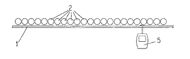
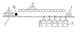
図1および図2には、ケーブルカー装置の必須構成要素が一方のステーシヨンの領域において示される。このケーブルカー装置は1群の減速タイヤ2、1群の牽引タイヤ3、および1群の加速タイヤ4が割り当てられるガイドレール1を含む。ケーブルカー装置の作動において、ゴンドラ5のごとき、乗客搬送体が矢印Aの方向に動かされる。ガイドレール1に沿って動かされる牽引ケーブルから連結解除された乗客搬送体5の速度が、減速タイヤ2によつて、乗客が乗客搬送体5を出入りすることができるように減速される。牽引タイヤ3によつて、乗客搬送体5は乗客が乗客搬送体を出入りすることができるケーブルカーステーシヨンの領域を通って動かされる。加速タイヤ4によつて、乗客搬送体5の速度が、結果として、例えば5m/sの、一定の速度で動かされる、牽引ケーブルに再び連結されるような範囲に増加される。なお、ケーブルカー装置には、牽引ケーブルの駆動を逆転するために、回転の向きを変えることが可能である少なくとも1つが駆動されている変向円板が設けられている。
【0012】
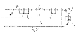
ケーブルカー装置が作動範囲外に置かれるとすぐにステーシヨン建物内に置かれたガイドレール1上に乗客搬送体を保管可能にするために、図4ないし図8に示されるように、1群の減速タイヤ2がガイドレール1から持ち上げられるようにする装置が設けられる。その後、すべての群のタイヤ2,3および4の牽引ケーブルの駆動が逆転され、それにより個々の乗客搬送体5を矢印Bの方向に動かす。結果として、乗客搬送体5は、屋外に置かれた区域からステーシヨン建物内に移動され、そして加速タイヤ4は減速タイヤとして作用する。牽引タイヤ3によつて、乗客搬送体5は、加速タイヤとして作用するけれども、持ち上げられてしまうため、係合しない、減速タイヤ2の領域に動かされる。その代わりに、減速タイヤは上昇された減速タイヤ2の領域にガイドレール1に沿って連続して次の乗客搬送体5により上方に押される。この領域の端部に設けられた減速タイヤ2aは、停止された状態に保持されることができ、かつ結果としてガイドレール1上に保管された乗客搬送体5用のストツパとして作用する。
【0013】
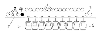
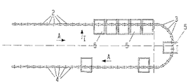
結果として、図5および図6に示されるように、多数の乗客搬送体5が、減速タイヤ2の領域において、ステーシヨン建物に配置された、ガイドレール1上に保管され得る。ケーブルカー装置作動の再開のために、装置は再び前進方向に駆動され、そして乗客搬送体5は、図7および図8に示されるように、牽引タイヤ3に個々に供給される。減速タイヤ2の領域に保管されたすべての乗客搬送体5が該減速タイヤから除去されると直ぐに、減速タイヤ2は再び下降され、そして結果として、それらはステーシヨンに入る乗客搬送体に作用し、かつ通常のケーブルカー作動が後に続く。
【0014】
さらに他の特徴において、1群の加速タイヤ4は上昇し得るように具体化され、かつ結果としてそれらは乗客搬送体5から係合解除され得る。結果として、乗客搬送体5は加速タイヤ4がそれに割り当てられるガイドレール1の領域に保管されることができる。その場合にケーブルカー装置の駆動は保管過程に関して逆転されるべきでない。その代わりに、乗客搬送体5は通常の作動方向においてケーブルカーステーシヨンに動かされ、該乗客搬送体5の速度は減速タイヤ2により減じられている。その後、該乗客搬送体は牽引タイヤ3によつて加速タイヤ4の領域に移動される。しかしながら、加速タイヤ4はそれらに作用しないので、乗客搬送体はそれらのタイヤに割り当てられたガイドレール1のこの領域に保管される。再び、第1の上昇されない加速タイヤは遮断し得るようにストツパとして作用する。
【0015】
図9及び図10を参照して、上昇し得る減速タイヤ2または加速タイヤ4の実施例を説明する。各乗客搬送体5はガイドレール1に沿って動き得る走行ギヤ51を備えている。各乗客搬送体5はまた、それにより牽引ケーブル10に連結され得る、締め付け装置52を備えている。最後に、各乗客搬送体5は、それに対して減速タイヤ2または加速タイヤ4が載置するようになる、駆動面53を備えている。減速タイヤ2または加速タイヤ4の駆動はタイヤ2または4と連係する駆動プーリ21のまわりに巻回されるベルトによつて行われる。個々の駆動プーリ間のギヤ比の適切な選択により、増加または減少する速度により駆動される連続するタイヤに対する要求が適宜に合致される。
【0016】
1群のタイヤ2または4はビーム61上に支持されており、該ビームにはボルト64によつてビーム61に堅固に接続された支持板63を復帰ばね65の作用に抗して上昇することができる制御シリンダ62が割り当てられる。油圧媒体がライン67を介してハンドポンプ66から制御シリンダ62に供給され得る。
【0017】
油圧媒体を制御シリンダ62に供給することにより、支持ビーム61は上昇され、かつ結果として1群のタイヤ2または4が乗客搬送体5の摩擦面53から持ち上げられる。結果として、減速タイヤ2または加速タイヤ4が上述した作動モードに要求される方法において乗客搬送体5から上昇され得る。上昇された位置が図10に示される。
【0018】
図11には、また、駆動プーリ21、クラツチ22、およびブレーキ23を備えている減速タイヤ2または加速タイヤ4が示される。このタイヤ2または4は堅固に固定されたビーム61により支持されるので、それは上昇不能である。クラツチ22によつて、該タイヤ2または4は駆動プーリ21から連結解除されかつブレーキ23に連結され、それによりこのタイヤ2または4の領域に侵入する乗客搬送体5を停止させる。この方法において、このタイヤはガイドレール1上に保管される乗客搬送体5用のストツパとして作用する。
【0019】
図12および図13により、牽引タイヤ3の実施例がまた説明され、該牽引タイヤによりガイドレール1上の乗客搬送体がまた牽引タイヤ3の領域に保管されることができる。牽引タイヤ3の個々のタイヤは図11に示される型の駆動装置を備えている。この例示の実施例において、他の牽引タイヤ3もそのように具体化される。
【0020】
牽引タイヤ3に割り当てられたガイドレール1の領域に乗客搬送体5を保管するために、ケーブルカー装置全体の駆動速度はおよそ1m/sに減少される。加えて、クラツチおよびブレーキを備えているそれらの牽引タイヤ3は1つが牽引タイヤ3aと同時に遮断されるようにケーブルカー装置の作動方向に抗して連続的に制御される。結果として、乗客搬送体5は牽引タイヤ3がそれに割り当てられるガイドレール1のその領域に動かされ、そしてストッパである牽引タイヤ3aへ連続して持ちこまれる。
【0021】
ケーブルカー装置を作動するために、牽引タイヤ3aの個々のタイヤは再び連続して作動状態に戻され、その結果乗客搬送体5は所定の間隔で再び牽引ケーブルに連結される。
【0022】
この種のケーブルカー装置において、乗客搬送体はまた作動時間外でステーシヨンに置かれたガイドレールに沿って保管され得る。保管は減速タイヤ、牽引タイヤおよび加速タイヤに割り当てられたガイドレールの領域の個々の領域において、またはこれらの領域のすべてにおいてなされることができる。かくして同様にステーシヨン建物が乗客搬送体を保管するのに使用され得る。
【0023】
【発明の効果】
叙上のごとく、本発明は、2つのステーシヨンを備え、少なくとも一つが駆動されている複数の変向円板上でステーシヨン内に案内される牽引ケーブルを備え、該牽引ケーブルに連結されるかまたはそれから連結解除され得るゴンドラまたは椅子のごとき多数の乗客搬送体を有し、前記ステーシヨンの領域に配置されるガイドレールを有し、該レールに沿って前記牽引ケーブルから連結解除された乗客搬送体が前記変向円板のまわりの連結解除領域から連結領域へ移動可能であり、そして前記ガイドレールに沿って動かされる乗客搬送体上に載置するようになる減速タイヤ、牽引タイヤおよび加速タイヤ群を有するケーブルカー装置において、前記減速タイヤ、牽引タイヤ、および/または加速タイヤの少なくとも幾つかが前記牽引ケーブルから連結解除される乗客搬送体に対して作動外に置かれることができ、前記減速タイヤ(2)および前記加速タイヤ(4)の少なくともいずれかが上昇可能であり、その結果としてこれらのタイヤ(2,4)が前記乗客搬送体(5)との係合から外され、前記乗客搬送体が、装置作動時間外に、これらのタイヤと連係される前記ガイドレールの領域に保管され得る構成としたので、作動時間外に乗客搬送体を保管するのに必要とされる空間が最小にされ得るケーブルカー装置を提供することができる。
【図面の簡単な説明】
【図1】本発明のケーブルカー装置の第1実施例を示す概略図である。
【図2】図1のケーブルカー装置を矢印Iの方向に見て示す概略図である。
【図3】図1および図2のケーブルカー装置の作動位置を示す概略図である。
【図4】図1および図2のケーブルカー装置の作動位置を示す概略図である。
【図5】図1および図2のケーブルカー装置の作動位置を示す概略図である。
【図6】図1および図2のケーブルカー装置の作動位置を示す概略図である。
【図7】図1および図2のケーブルカー装置の作動位置を示す概略図である。
【図8】図1および図2のケーブルカー装置の作動位置を示す概略図である。
【図9】図1ないし図8のケーブルカー装置の細部を示す側面図である。
【図10】図1ないし図8のケーブルカー装置の細部を図9と異なる位置において示す側面図である。
【図11】図1ないし図8のケーブルカー装置の細部を示す部分断面側面図である。
【図12】本発明によるケーブルカー装置のさらに他の実施例を作動状態において示す概略図である。
【図13】図12のケーブルカー装置を他の作動状態において示す概略図である。
【符号の説明】
1 ガイドレール
2 減速タイヤ
2a 減速タイヤ
3 牽引タイヤ
3a 牽引タイヤ
4 加速タイヤ
5 乗客搬送体
10 牽引ケーブル
21 駆動プーリ
22 クラツチ
23 ブレーキ(制動装置)
51 走行ギア
52 締め付け金具
53 駆動面
61 ビーム
62 制御シリンダ
63 支持板
64 ボルト
65 復帰ばね
66 ハンドポンプ
67 ライン[0001]
[Field of the Invention]
The invention comprises two stations, in particular a lower station and an upper station, comprising a traction cable guided in the station on a plurality of turning discs, at least one of which is driven, connected to the traction cable Passenger transport having a large number of passenger transports, such as gondolas or chairs that can be disconnected from it, or guide rails arranged in the area of the station, and disconnected from the traction cable along the rails A reduction tire, a traction tire and an acceleration tire whose body is movable from a connection release region around the turning disc to a connection region and is placed on a passenger transport body moved along the guide rail The present invention relates to a cable car device having a group.
[0002]
[Prior art]
In this kind of known cable car device, it is necessary to disconnect the passenger carrier from the traction cable outside the operating time and store it in the room provided for them, a so-called garage. In addition to the station building, a building that must be built and operated is provided for this purpose. Inside the station building, the passenger carrier side line is linked to a guide rail followed by a connecting rail extending to the storage room. As soon as the cable car device is put out of service, the passenger carrier is decoupled from the tow cable and is routed via side wires and connecting rails to the garage where they are stored outside the cable car device operating time. The This is particularly the requirement that exists when the passenger carrier remains along the path of the cable car device outside the operating hours, the passenger carrier must be prepared for resumption of operation such as scraping snow from the passenger carrier. Make it unnecessary.
[0003]
However, in this kind of known cable car apparatus, it is necessary to create a sufficient space for storing the passenger carrier. If this space is created in the lower station of the cable car system, then some land must be available for it. In this case, the additional land is not always available, and even if it is available, the cost generally increases greatly. Conversely, creating this space in the area of the upper station entails a very high cost in the construction and operation of additional buildings.
[0004]
[Problems to be solved by the invention]
Accordingly, it is an object of the present invention to create a cable car device that can minimize the space required to store passenger transporters outside operating hours. The present invention is based on the idea of using the space available in the station building to store passenger carriers. This use has already been proposed per se, however, the hindrance is that the deceleration, traction and acceleration tires located in the station building have the same drive. In order to be able to use further station buildings to store passenger vehicles, individual drive tires must be individually controllable, which requires a very high level of technical effort and at the same time With high costs.
[0005]
Thus, the present invention creates a cable car device in which the mode of operation of the individual drive tire groups can be controlled in a simple manner so that the space available in the station building can also be used to store passenger carriers. The purpose is to do.
[0006]
[Means for Solving the Problems]
According to the invention, this can be put out of operation with respect to a passenger vehicle in which at least some of the deceleration, traction and / or acceleration tires are decoupled from the traction cable, as a result. This is achieved by the fact that the passenger carrier can be stored in the area of the guide rails associated with these tires outside the device operating time.
[0007]
The present invention also allows the deceleration tires and acceleration tires to be raised so that these tires can be disengaged from the passenger carrier. The deceleration tire or the acceleration tire can rise against the action of the return force, in particular against the action of the return spring. In particular, the deceleration tire or acceleration tire can be raised hydraulically. Moreover, preferably one of the tires adjacent to the ascending tire can be disconnected from the drive mechanism and controlled by a brake.
[0008]
In yet another preferred embodiment, the clutch is associated with a group of traction tires that allow the tires to be disconnected from the drive mechanism and the braking device is also associated with these tires. In particular, the clutch and the braking device are linked with the other tires of the traction tire.
[0009]
A preferred method for storing the passenger vehicle in the cable car device is placed out of operation with respect to the passenger vehicle in which at least some of the deceleration, traction and / or acceleration tires are disconnected from the traction cable. And the passenger carrier placed along the aisle is moved by the station, disconnected from the traction cable, and stored in the region of the guide rail associated with the tire placed out of operation.
[0010]
The subject matter of the invention is explained in more detail below by means of an exemplary embodiment shown in the drawings.
[0011]
DETAILED DESCRIPTION OF THE INVENTION
1 and 2 show the essential components of a cable car device in the area of one station. The cable car device includes a guide rail 1 to which a group of deceleration tires 2, a group of
[0012]
In order to be able to store the passenger transport on the guide rail 1 placed in the station building as soon as the cable car device is placed outside the operating range, as shown in FIGS. A device is provided that allows the deceleration tire 2 to be lifted from the guide rail 1. Thereafter, the drive of the traction cables of all groups of
[0013]
As a result, as shown in FIGS. 5 and 6, a large number of
[0014]
In yet another feature, the group of acceleration tires 4 is embodied such that they can rise and as a result they can be disengaged from the
[0015]
With reference to FIG.9 and FIG.10, the Example of the deceleration tire 2 or the acceleration tire 4 which can raise is demonstrated. Each
[0016]
A group of tires 2 or 4 is supported on a
[0017]
By supplying the hydraulic medium to the
[0018]
FIG. 11 also shows a reduction tire 2 or an acceleration tire 4 that includes a
[0019]
With reference to FIGS. 12 and 13, an embodiment of the
[0020]
In order to store the
[0021]
In order to operate the cable car device, the individual tires of the
[0022]
In this type of cable car device, the passenger carrier can also be stored along a guide rail placed on the station outside the operating hours. Storage can be done in individual areas of the area of the guide rail assigned to the deceleration tire, traction tire and acceleration tire or in all of these areas. Thus, similarly, a station building can be used to store passenger carriers.
[0023]
【The invention's effect】
As mentioned above, the present invention comprises a traction cable comprising two stations and guided in the station on a plurality of deflection disks, at least one of which is driven, connected to the traction cables or A passenger carrier having a number of passenger carriers such as gondolas or chairs that can then be disconnected, having guide rails arranged in the area of the station, and disconnected from the traction cable along the rails. A reduction tire, a traction tire, and an acceleration tire group that are movable from a connection release region around the turning disc to a connection region and that are to be placed on a passenger transport body that is moved along the guide rail. A cable car apparatus having at least some of the deceleration tire, the traction tire, and / or the acceleration tire is the traction cable. Can be placed out of operation with respect to the passenger carrier to be al uncoupled, said at least one of the deceleration tire (2) and the acceleration tire (4) can be increased, these tires as a result ( 2 and 4) are disengaged from the passenger carrier (5), and the passenger carrier can be stored in the area of the guide rail associated with these tires outside the device operating time; Therefore, it is possible to provide a cable car device that can minimize the space required to store the passenger transporter outside the operation time.
[Brief description of the drawings]
FIG. 1 is a schematic view showing a first embodiment of a cable car device of the present invention.
2 is a schematic view showing the cable car device of FIG. 1 as viewed in the direction of arrow I. FIG.
FIG. 3 is a schematic view showing an operating position of the cable car device of FIGS. 1 and 2;
4 is a schematic view showing an operating position of the cable car device of FIGS. 1 and 2. FIG.
FIG. 5 is a schematic view showing an operating position of the cable car device of FIGS. 1 and 2;
6 is a schematic view showing an operating position of the cable car device of FIGS. 1 and 2. FIG.
7 is a schematic view showing an operating position of the cable car device of FIGS. 1 and 2. FIG.
8 is a schematic view showing an operating position of the cable car device of FIGS. 1 and 2. FIG.
FIG. 9 is a side view showing details of the cable car device of FIGS. 1 to 8;
10 is a side view showing details of the cable car device of FIGS. 1 to 8 at a position different from FIG. 9; FIG.
11 is a partial cross-sectional side view showing details of the cable car device of FIGS. 1 to 8; FIG.
FIG. 12 is a schematic view showing still another embodiment of the cable car device according to the present invention in an operating state;
13 is a schematic view showing the cable car device of FIG. 12 in another operating state.
[Explanation of symbols]
DESCRIPTION OF SYMBOLS 1 Guide rail 2
51
Claims (7)
前記減速タイヤ(2)、牽引タイヤ(3)、および加速タイヤ(4)の少なくとも幾つかが前記牽引ケーブル(10)から連結解除される乗客搬送体に対して作動外に置かれることができ、
前記減速タイヤ(2)および前記加速タイヤ(4)の少なくともいずれかが上昇可能であり、その結果としてこれらのタイヤ(2,4)が前記乗客搬送体(5)との係合から外され、前記乗客搬送体が、装置作動時間外に、これらのタイヤと連係される前記ガイドレール(1)の領域に保管され得ることを特徴とするケーブルカー装置。Numerous passenger transports comprising two stations, with a traction cable guided in the station on a plurality of turning discs, at least one of which is driven, which can be connected to or disconnected from the traction cable And a guide rail disposed in the area of the station, the passenger transport body being disconnected from the traction cable along the rail is connected from the connection release area around the turning disc. In a cable car device having a deceleration tire, a traction tire and an acceleration tire group that can be moved to and mounted on a passenger carrier moved along the guide rail,
At least some of the deceleration tire (2), traction tire (3), and acceleration tire (4) may be placed out of operation with respect to a passenger carrier that is decoupled from the traction cable (10);
At least one of the deceleration tire (2) and the acceleration tire (4) can be raised, with the result that these tires (2, 4) are disengaged from the passenger carrier (5), Cable car device characterized in that the passenger carrier can be stored in the region of the guide rail (1) associated with these tires outside the device operating time.
前記減速タイヤ(2)および前記加速タイヤ(4)の少なくともいずれかが上昇可能であり、その結果としてこれらのタイヤ(2,4)が前記乗客搬送体(5)との係合から外され、通路に沿って置かれる乗客搬送体(5)が前記ステーシヨンに動かされ、前記ケーブル(10)から連結解除され、そして作動外に置かれた前記タイヤ(2,4)と連係する前記ガイドレール(1)の領域に保管されることを特徴とする請求項1ないし6のいずれか1項に記載のケーブルカー装置において乗客搬送体を保有する方法。At least some of the deceleration tire (2), traction tire (3) and acceleration tire (4) are placed out of operation with respect to the passenger carrier (5) to be disconnected from the traction cable (10);
At least one of the deceleration tire (2) and the acceleration tire (4) can be raised, with the result that these tires (2, 4) are disengaged from the passenger carrier (5), The guide rail (5) placed along the aisle is moved by the station, disconnected from the cable (10) and associated with the tires (2, 4) placed out of operation ( The method for holding a passenger carrier in the cable car device according to any one of claims 1 to 6, wherein the passenger carrier is stored in the area 1).
Applications Claiming Priority (2)
| Application Number | Priority Date | Filing Date | Title |
|---|---|---|---|
| AT1860-95 | 1995-11-14 | ||
| AT0186095A AT405270B (en) | 1995-11-14 | 1995-11-14 | ROPEWAY SYSTEM |
Publications (2)
| Publication Number | Publication Date |
|---|---|
| JPH09169263A JPH09169263A (en) | 1997-06-30 |
| JP3662374B2 true JP3662374B2 (en) | 2005-06-22 |
Family
ID=3522568
Family Applications (1)
| Application Number | Title | Priority Date | Filing Date |
|---|---|---|---|
| JP30335396A Expired - Lifetime JP3662374B2 (en) | 1995-11-14 | 1996-11-14 | Cable car equipment |
Country Status (7)
| Country | Link |
|---|---|
| EP (1) | EP0774392B2 (en) |
| JP (1) | JP3662374B2 (en) |
| KR (1) | KR100416524B1 (en) |
| CN (1) | CN1078550C (en) |
| AT (2) | AT405270B (en) |
| DE (1) | DE59601937D1 (en) |
| ES (1) | ES2133921T5 (en) |
Families Citing this family (15)
| Publication number | Priority date | Publication date | Assignee | Title |
|---|---|---|---|---|
| CH692694A5 (en) | 1997-12-19 | 2002-09-30 | Garaventa Holding Ag | Cable railway line has two stations, particularly valley station and mountain top station, together with conveyor cable fed over deflector wheels in stations, one wheel being driven and several drive devices |
| AT409256B (en) * | 1999-01-27 | 2002-07-25 | High Technology Invest Bv | DEVICE FOR EMERGENCY BRAKING OF TRANSPORT |
| EP1424257B1 (en) * | 2002-07-16 | 2005-04-13 | Innova Patent GmbH | Rope railway system with a support and haulage cable and with coupled vehicles formed by cabins and chairs |
| ITBZ20020038A1 (en) | 2002-10-01 | 2004-04-02 | High Technology Invest Bv | PROVISION FOR THE MAINTENANCE OF TRANSPORT SYSTEMS |
| CN100383001C (en) * | 2004-08-26 | 2008-04-23 | 杜力 | Method for producing short distance passengar service equipment |
| AT504615A3 (en) * | 2006-12-04 | 2010-12-15 | Innova Patent Gmbh | DEVICE FOR STORING DRIVING EQUIPMENT OF A CABLE CARRIER IN A STORAGE AREA |
| AT504613B1 (en) * | 2006-11-27 | 2011-02-15 | Innova Patent Gmbh | CABLE CAR WITH A STATION FOR STORING DRIVING EQUIPMENT |
| NZ592922A (en) * | 2010-08-19 | 2012-08-31 | Innova Patent Gmbh | Pivotally mounted rocker carrying supporting roller(s) via which tire wheels are driven |
| AT12625U1 (en) * | 2010-10-18 | 2012-09-15 | Innova Patent Gmbh | CABLE CAR SYSTEM |
| CH705311B1 (en) * | 2011-07-27 | 2016-02-15 | Bartholet Maschb Ag | A method for moving and Garagieren of transportation devices in a station building a cableway system. |
| AT515098B1 (en) * | 2013-11-28 | 2015-06-15 | Innova Patent Gmbh | Plant for the transport of persons |
| FR3025163B1 (en) * | 2014-09-01 | 2016-08-26 | Pomagalski Sa | INSTALLATION AND METHOD FOR TRANSPORTING BY AIR CABLE |
| US10889305B2 (en) | 2016-02-18 | 2021-01-12 | Innova Patent Gmbh | Apparatus for moving ropeway vehicles in a ropeway system |
| CN108058714A (en) * | 2016-11-05 | 2018-05-22 | 陈祥辉 | Three rope sheave of multiple-energy-source bi-motor voluntarily cable car |
| CN111217097A (en) * | 2020-01-09 | 2020-06-02 | 湘潭大学 | Guide wheel device with adjustable wheel rail compression degree |
Family Cites Families (7)
| Publication number | Priority date | Publication date | Assignee | Title |
|---|---|---|---|---|
| CH452581A (en) * | 1965-09-24 | 1968-03-15 | Wallmannsberger Georg Ing Dr | Circulating cable car in two-cable operation for high conveying capacity, with wagons that can be coupled to the pulling cable |
| FR2333684A1 (en) * | 1975-12-04 | 1977-07-01 | Baudin Chateauneuf | Accelerating and braking ramp - for cable operated vehicles has entry and exit rails, conveyor with wedges and automatically adjustable exit slope |
| CH671552A5 (en) * | 1986-06-17 | 1989-09-15 | Von Roll Transportsysteme | |
| FR2605574B1 (en) * | 1986-10-23 | 1990-06-08 | Creissels Denis Sa | TRANSPORTATION SYSTEM HAVING A CONTINUOUSLY SCROLLING AIR CABLE AND LAUNCHER AND RETARDER SYSTEMS |
| DE3872630D1 (en) * | 1987-09-09 | 1992-08-13 | Von Roll Transportsysteme | TRACK DEVICE FOR THE VEHICLES OF A CONVEYOR, IN PARTICULAR CIRCULAR ROPE CONVEYOR. |
| FR2654052B1 (en) * | 1989-11-03 | 1992-01-03 | Reel Sa | PROCESS FOR STARTING AND STOPPING AN AIR CABLE TRANSPORTATION SYSTEM. |
| FR2661147B1 (en) * | 1990-04-24 | 1992-07-24 | Pomagalski Sa | TENSIONER TENSION END STATION. |
-
1995
- 1995-11-14 AT AT0186095A patent/AT405270B/en not_active IP Right Cessation
-
1996
- 1996-10-10 DE DE59601937T patent/DE59601937D1/en not_active Expired - Lifetime
- 1996-10-10 AT AT96890160T patent/ATE180225T1/en active
- 1996-10-10 ES ES96890160T patent/ES2133921T5/en not_active Expired - Lifetime
- 1996-10-10 EP EP96890160A patent/EP0774392B2/en not_active Expired - Lifetime
- 1996-11-11 CN CN96121306A patent/CN1078550C/en not_active Expired - Lifetime
- 1996-11-13 KR KR1019960053561A patent/KR100416524B1/en not_active IP Right Cessation
- 1996-11-14 JP JP30335396A patent/JP3662374B2/en not_active Expired - Lifetime
Also Published As
| Publication number | Publication date |
|---|---|
| CN1078550C (en) | 2002-01-30 |
| AT405270B (en) | 1999-06-25 |
| JPH09169263A (en) | 1997-06-30 |
| EP0774392B1 (en) | 1999-05-19 |
| CN1150567A (en) | 1997-05-28 |
| ATA186095A (en) | 1998-11-15 |
| EP0774392B2 (en) | 2003-05-07 |
| ATE180225T1 (en) | 1999-06-15 |
| EP0774392A1 (en) | 1997-05-21 |
| KR970026664A (en) | 1997-06-24 |
| KR100416524B1 (en) | 2004-04-28 |
| DE59601937D1 (en) | 1999-06-24 |
| ES2133921T3 (en) | 1999-09-16 |
| ES2133921T5 (en) | 2003-12-16 |
Similar Documents
| Publication | Publication Date | Title |
|---|---|---|
| JP3662374B2 (en) | Cable car equipment | |
| US3225704A (en) | Transportation systems | |
| US5562040A (en) | Rope guide system for an aerial ropeway, particularly a circuital aerial ropeway | |
| US3871303A (en) | Transportation system | |
| KR102549651B1 (en) | Device for coupling a vehicle to a traction cable, vehicle provided with such a device, and traction cable transport apparatus including such a vehicle | |
| US5517923A (en) | Cable drawn vehicle having an on-board motor | |
| KR20110053468A (en) | Carrying device for relocating a car of an elevator | |
| US4083309A (en) | Continuous transport systems | |
| EP0922620B2 (en) | Procedure for storage and removal from storage of cabins within the stations of an aerial cable railway installation | |
| RU2410260C2 (en) | Overhead ropeway with stations intended for accumulation of movable appliances | |
| JPS61291264A (en) | Ropeway conveyor | |
| US5419261A (en) | Passenger transport installation having a plurality of track sections | |
| US3812788A (en) | Transport installation with independent vehicles | |
| US20110226152A1 (en) | Passenger transport installation comprising independent vehicles travelling on tracks and hauled by cables, and method for transporting passengers | |
| US20220379929A1 (en) | Cable Transport With Transport Vehicle For Conveying An Object | |
| US5819668A (en) | System for the transportation of persons and/or goods | |
| CN108137063B (en) | Cable transport installation | |
| EP3658436B1 (en) | Cable or similar transport installation, and vehicle suitable for such installation | |
| JPH09215140A (en) | Overhead cable way having movable take-up module | |
| KR100372790B1 (en) | Passenger and cargo transportations | |
| JPH08207749A (en) | Garage for continuous cableway | |
| CN1098183C (en) | Transporting equipment driven by steel cable, and method for operating same | |
| JPH02100988A (en) | Cable type conveyor | |
| NL1002830C1 (en) | Linear electromagnetic vehicle traction | |
| CH692192A5 (en) | Clock means for charging the station track a circulating cableway with detachable her hauling cable cars. |
Legal Events
| Date | Code | Title | Description |
|---|---|---|---|
| A131 | Notification of reasons for refusal |
Free format text: JAPANESE INTERMEDIATE CODE: A131 Effective date: 20040512 |
|
| A601 | Written request for extension of time |
Free format text: JAPANESE INTERMEDIATE CODE: A601 Effective date: 20040714 |
|
| A602 | Written permission of extension of time |
Free format text: JAPANESE INTERMEDIATE CODE: A602 Effective date: 20040720 |
|
| A521 | Request for written amendment filed |
Free format text: JAPANESE INTERMEDIATE CODE: A523 Effective date: 20041110 |
|
| TRDD | Decision of grant or rejection written | ||
| A01 | Written decision to grant a patent or to grant a registration (utility model) |
Free format text: JAPANESE INTERMEDIATE CODE: A01 Effective date: 20050302 |
|
| A61 | First payment of annual fees (during grant procedure) |
Free format text: JAPANESE INTERMEDIATE CODE: A61 Effective date: 20050323 |
|
| R150 | Certificate of patent or registration of utility model |
Free format text: JAPANESE INTERMEDIATE CODE: R150 |
|
| FPAY | Renewal fee payment (event date is renewal date of database) |
Free format text: PAYMENT UNTIL: 20080401 Year of fee payment: 3 |
|
| FPAY | Renewal fee payment (event date is renewal date of database) |
Free format text: PAYMENT UNTIL: 20090401 Year of fee payment: 4 |
|
| FPAY | Renewal fee payment (event date is renewal date of database) |
Free format text: PAYMENT UNTIL: 20100401 Year of fee payment: 5 |
|
| FPAY | Renewal fee payment (event date is renewal date of database) |
Free format text: PAYMENT UNTIL: 20110401 Year of fee payment: 6 |
|
| FPAY | Renewal fee payment (event date is renewal date of database) |
Free format text: PAYMENT UNTIL: 20130401 Year of fee payment: 8 |
|
| FPAY | Renewal fee payment (event date is renewal date of database) |
Free format text: PAYMENT UNTIL: 20130401 Year of fee payment: 8 |
|
| FPAY | Renewal fee payment (event date is renewal date of database) |
Free format text: PAYMENT UNTIL: 20140401 Year of fee payment: 9 |
|
| R250 | Receipt of annual fees |
Free format text: JAPANESE INTERMEDIATE CODE: R250 |
|
| R250 | Receipt of annual fees |
Free format text: JAPANESE INTERMEDIATE CODE: R250 |
|
| R250 | Receipt of annual fees |
Free format text: JAPANESE INTERMEDIATE CODE: R250 |
|
| EXPY | Cancellation because of completion of term |