JP3662334B2 - Wall slitting machine - Google Patents
Wall slitting machine Download PDFInfo
- Publication number
- JP3662334B2 JP3662334B2 JP07907696A JP7907696A JP3662334B2 JP 3662334 B2 JP3662334 B2 JP 3662334B2 JP 07907696 A JP07907696 A JP 07907696A JP 7907696 A JP7907696 A JP 7907696A JP 3662334 B2 JP3662334 B2 JP 3662334B2
- Authority
- JP
- Japan
- Prior art keywords
- housing
- stopper
- carriage
- depth
- stopper element
- Prior art date
- Legal status (The legal status is an assumption and is not a legal conclusion. Google has not performed a legal analysis and makes no representation as to the accuracy of the status listed.)
- Expired - Lifetime
Links
Images


Classifications
-
- B—PERFORMING OPERATIONS; TRANSPORTING
- B28—WORKING CEMENT, CLAY, OR STONE
- B28D—WORKING STONE OR STONE-LIKE MATERIALS
- B28D1/00—Working stone or stone-like materials, e.g. brick, concrete or glass, not provided for elsewhere; Machines, devices, tools therefor
- B28D1/02—Working stone or stone-like materials, e.g. brick, concrete or glass, not provided for elsewhere; Machines, devices, tools therefor by sawing
- B28D1/04—Working stone or stone-like materials, e.g. brick, concrete or glass, not provided for elsewhere; Machines, devices, tools therefor by sawing with circular or cylindrical saw-blades or saw-discs
-
- B—PERFORMING OPERATIONS; TRANSPORTING
- B27—WORKING OR PRESERVING WOOD OR SIMILAR MATERIAL; NAILING OR STAPLING MACHINES IN GENERAL
- B27B—SAWS FOR WOOD OR SIMILAR MATERIAL; COMPONENTS OR ACCESSORIES THEREFOR
- B27B9/00—Portable power-driven circular saws for manual operation
- B27B9/02—Arrangements for adjusting the cutting depth or the amount of tilting
-
- B—PERFORMING OPERATIONS; TRANSPORTING
- B28—WORKING CEMENT, CLAY, OR STONE
- B28D—WORKING STONE OR STONE-LIKE MATERIALS
- B28D1/00—Working stone or stone-like materials, e.g. brick, concrete or glass, not provided for elsewhere; Machines, devices, tools therefor
- B28D1/02—Working stone or stone-like materials, e.g. brick, concrete or glass, not provided for elsewhere; Machines, devices, tools therefor by sawing
- B28D1/04—Working stone or stone-like materials, e.g. brick, concrete or glass, not provided for elsewhere; Machines, devices, tools therefor by sawing with circular or cylindrical saw-blades or saw-discs
- B28D1/045—Sawing grooves in walls; sawing stones from rocks; sawing machines movable on the stones to be cut
-
- B—PERFORMING OPERATIONS; TRANSPORTING
- B28—WORKING CEMENT, CLAY, OR STONE
- B28D—WORKING STONE OR STONE-LIKE MATERIALS
- B28D1/00—Working stone or stone-like materials, e.g. brick, concrete or glass, not provided for elsewhere; Machines, devices, tools therefor
- B28D1/18—Working stone or stone-like materials, e.g. brick, concrete or glass, not provided for elsewhere; Machines, devices, tools therefor by milling, e.g. channelling by means of milling tools
- B28D1/183—Hand tools, e.g. portable, motor driven
Abstract
Description
【0001】
【技術分野】
本発明は壁面にスリットを加工するための加工装置に関し、特に、一対の握りを有するハウジングと、少なくとも一枚のディスクから成るスリット加工用工具を駆動するための駆動ユニットとを具え、前記ハウジングはキャリッジに対して工具のディスク面と平行な面内で第一端部領域における軸受を中心としてばね力に抗して旋回可能であり、第二端部領域においてキャリッジには、該キャリッジからの工具の突出量を調整可能な深度ストッパを受けるべく、ハウジングに向けて突出する係止レール)を設けると共にハウジングには係止レールと協働するストッパ素子を設け、該ストッパ素子は一方の握りに配置した係止スイッチによって係止可能としてなる壁面スリット加工装置に係るものである。
【0002】
【背景技術】
新築、改築、増築などに伴う電気配線工事に際しては、各種の電気ケーブルを収めるための電気配管を敷設する。床、天井、壁などのコンクリート製構造部材の場合、通常、型板にコンクリートを打設する前に、電気配管を型板に固定する。コンクリート構造部材から突出する電気配管を既設壁面に敷設するため、壁面スリット加工装置を使用し、互いに平行に延在する二本のスリットを壁面に切り込んでスリットを形成する。スリットの深さと間隔は、敷設すべき電気配管の数と直径とに依存する。壁のスリット間の材料を適当な工具を用いて除去し、電気配管を収めるための受け溝を作成する。
【0003】
ドイツ連邦共和国特許出願公開第3815245号公報に開示された既知の壁面スリット加工装置は、 ハウジングと、 少なくとも一枚のディスクからなるスリット加工工具駆動すべくハウジングに結合した駆動ユニットと、 キャリッジとを具える。初期位置において、ハウジングはキャリッジに対して傾斜位置を占めるため、スリット工具は基盤に乗り上げるキャリッジから突出しない。ハウジングは、スリット工具のディスク面に対して平行に、キャリッジの第一端部領域に配置した軸受を中心として、ばね素子の力に抗して動作位置まで旋回可能である。ハウジングとキャリッジとの間における旋回角度を制限するため、キャリッジからハウジングに向けて突出する係止レールの遊端は、ハウジングに配置したストッパ素子の舌状部分に接触する。このストッパ素子は、握りに配置した係止スイッチに結合し、係止スイッチは作動時に長手方向軸線を中心とするストッパ素子および舌状部分のばね力に抗しての回動を生じさせる。係止スイッチを解除するとストッパ素子は初期位置に復帰する。係止レール上に深度ストッパが設けられ、この深度ストッパは係止レールに沿って段階的に調節可能とされている。
【0004】
この既知の加工装置において、作業者は、スリット加工作業に必要な強い押圧力のみならず、キャリッジとハウジングとの間に配置したばねを圧縮させるための力を作業時間の全体に亙って集約しなければならない。この追加的な負担により作業車が早期に疲労するため、押圧力は弱まる。その結果、スリットの一定深さを維持するのが困難となる。
【0005】
【発明の開示】
本発明の課題は、特に壁基盤に一定深さのスリットを僅かな労力で容易かつ確実に作成可能とする壁面スリット加工装置を提案することにある。
【0006】
この課題を解決するため、本発明は、前述した構成の壁面スリット加工装置において、深度ストッパをストッパ素子に係止可能とすることを特徴とするものである。
【0007】
基盤にスリット加工を施すに際して、ハウジングはキャリッジおよび係止レールに対して旋回させる。ハウジングが深度ストッパに接すると、深度ストッパはハウジングのストッパ素子を係止する。そのため、ハウジングとキャリッジとの間に配置したばねで付勢されているにも拘わらず、ハウジングを深度ストッパから分離することが不可能となる。したがって、ばね力に対抗する力を作業時間に亙って追加的に及ぼす必要はない。
【0008】
ハウジングを深度ストッパに固定する場合、ストッパ素子の停止面と協働し、かつ、ストッパ素子に向けて突出する係止アームを用いることが有利である。
【0009】
ストッパ素子には、係止アームを弾性的に回避させるガイド輪郭を持たせるのが有利である。この場合、係止アームとストッパとが結合する前に、係止アームはハウジングがキャリッジに対して旋回する際に側方へ回避可能となる。
【0010】
ストッパ素子に配置したストッパは、係止レールおよびキャリッジとは反対側に向けられた停止面から形成する。係止アームに湾曲端を設け、ストッパ素子の停止面に対してほぼ平行に延在する停止エッジとする。ハウジングの境界面が深度ストッパに接する場合にその固定を可能とするため、ストッパ素子に対向した深度ストッパの停止面と係止アームの停止エッジとの間隔は、少なくとも深度ストッパに対向したハウジングの境界面と停止面として形成したストッパ素子のストッパとの間隔と一致させるのが有利である。
【0011】
機能上の理由により、係止アームばね鋼製とするのが有利である。
【0012】
【最良の実施形態】
以下、図示実施例につき本発明を一層具体的に説明する。
【0013】
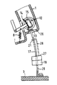
図1に示した壁面スリット加工装置は、ハウジング1と、少なくとも一枚のディスク5からなるスリット工具4を駆動し得るようハウジング1に結合した駆動ユニット2と、キャリッジ3とから構成する。ハウジング1は、その第一端部領域に配置した軸受6を中心として、スリット工具4のディスク面に平行な面内でキャリッジ3に対してばね7の力に抗して旋回可能である。
【0014】
キャリッジ3の偶部にローラ23を配置し、これらローラ23は被加工基盤U上でキャリッジ3を一層良好に変位させるものである。ローラ23はキャリッジ3および加工装置全体を、もっぱら加工装置の長手方向と平行な方向にのみ変位させる配置とする。
【0015】
駆動ユニット2と結合した歯車機構(図示せず)は出力軸24を有し、 この出力軸24はハウジング1の長手方向に対して直角に延在させる。スリット工具4を形成する二枚のディスク5は、出力軸24に固定する。
【0016】
軸受6を介してキャリッジ3と結合した第一端部領域のみならず第二端部領域においても、ハウジング1には各一個の突出した握り9,10を設ける。
【0017】
ハウジング1上で、握り9,10の間に吸込管20を配置する。握り9,10の間でハウジング1から突出する電気ケーブル16は保持素子22によりに吸込管20定着可能とする。
【0018】
加工装置の第一端部領域に配置した握り10には駆動ユニット2を作動させるための電気スイッチ25を設ける。
【0019】
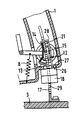
加工装置の第二端部領域に配置した握り9には係止スイッチ11を設け、係止スイッチ11は作動時にハウジング1とキャリッジ3との間における旋回運動を制限するストッパ素子12をばね素子8の力に抗して回動させる。図2に示すように、係止スイッチは押し込まれないストッパ12の係止位置においては、ストッパ素子12の舌状部分13がキャリッジ3からハウジング1に向けて突出する係止レール17の遊端において支持される。
【0020】
係止レール17には、図示しないクランプ領域を有する深度ストッパ18を配置し、この深度ストッパ18は係止レール17に沿って段階的に調節可能とする。その際、クランプ領域は係止レール17の噛合領域29に形状結合する。同様に、キャリッジ3から突出する調整目盛り19により深度ストッパ18を任意のスリット深さに調整可能とする。
【0021】
係止スイッチ11を作動すると、図3に示すように、ストッパ素子12は伝達素子によって係止位置から開放位置まで回動する。その結果、ストッパ素子12における舌状部分13が係止レール17から解放され、ハウジング1が係止レール17またはキャリッジ3に対して旋回可能となる。
【0022】
図5に示すように、ハウジング1における深度ストッパ18に対向する境界面26は係止レール17に配置した深度ストッパ18の停止面27に接触し、係止スイッチ11が作動している限り任意のスリット深さに調整した深度ストッパ18に対してハウジング1を固定することができる。したがって加工装置は動作位置を占め、スリット工具4のディスク5は、被加工基盤U上に乗り上げたキャリッジ3から、調整目盛り19によって読み取り可能な分だけ突出する。深度ストッパ18にハウジング1を固定する結果、ストッパ素子12の停止面14と協働し、ストッパ素子12に向けて突出する係止アーム28を有する深度ストッパ18を用いて可能となる。停止面14は、係止レール17またはキャリッジ3とは反対側の停止面として形成する。係止アーム28に湾曲端を設けて、ストッパ素子12の停止面14に対してほぼ平行に延在する停止エッジ21を形成する。停止エッジ21は停止面14を把持可能とし、これによってハウジング1を深度ストッパ18のみならずキャリッジ3に対しても固定可能とする。
【0023】
図4に示すように、ハウジング1がキャリッジ3に対して旋回する際に、係止アーム28の停止エッジ21に対して停止面14がほぼ平行に変位する場合にのみ、ストッパ素子12の停止面14は把持可能となる。ストッパ素子12は、係止アーム28を弾性的に回避させると共に停止エッジ21をほぼ平行に変位させるガイド輪郭15を有する。ハウジング1が旋回する間、係止アーム28の湾曲端はストッパ素子12のガイド輪郭15に接触して側方に変位し、その際、弾性材料から形成した係止アーム28を付勢させる。ハウジング1の境界面26が深度ストッパ18の停止面27に接触して動作位置に到達すると、係止アーム28の遊端はストッパ素子12のガイド輪郭15から離れ、 係止アーム28は初期位置に復帰してストッパ素子12の停止面14を把持する。
【0024】
ハウジング1の境界面26が深度ストッパ18に接触する場合、係止アーム28の停止エッジ21を有する停止面として形成したストッパ素子12の停止面14を把持可能とするため、ストッパ素子12に対向する深度ストッパ18の停止面27と係止アーム28の停止エッジ21との間隔A1は、少なくとも深度ストッパ18に対向するハウジング1の境界面26とストッパ素子12のストッパ14との間隔A2と一致させるのが有利である。
【0025】
ハウジング1とキャリッジ3との間に配置したばね7が付勢するにも拘わらず、キャリッジ3に対してハウジング1を開放すること、またはハウジング1を深度ストッパ18から取り外すことは不可能である。係止スイッチ11を解除した後、ストッパ素子12は初期位置まで回動復帰する。それにより、ストッパ素子12の停止面14と係止アーム28の停止エッジ21との間における係合が解除される。ハウジング1がキャリッジ3から離間し、加工装置は再び初期位置を占めることができる。
【図面の簡単な説明】
【図1】図1は、本発明による壁面スリット加工装置の停止状態を示す正面図である。
【図2】図2は、図1の加工装置の係止機構をキャリッジに対するハウジングの一作動位置で示す断面図である。
【図3】図3は、図1の加工装置の係止機構をキャリッジに対するハウジングの他の作動位置で示す断面図である。
【図4】図4は、図1の加工装置の係止機構をキャリッジに対するハウジングの他の作動位置で示す断面図である。
【図5】図5は、図1の加工装置の係止機構をキャリッジに対するハウジングの他の作動位置で示す断面図である。
【符号の説明】
1 ハウジング
2 駆動ユニット
3 キャリッジ
4 加工工具
5 ディスク
6 軸受
7 ばね
9,10 握り
11 係止スイッチ
12 ストッパ素子
14 停止面
15 ガイド輪郭
17 係止レール
18 深度ストッパ
21 停止エッジ
26 境界面
27 停止面
28 係止アーム[0001]
【Technical field】
The present invention relates to a machining apparatus for machining a slit on a wall surface, and in particular, includes a housing having a pair of grips and a drive unit for driving a slit machining tool including at least one disk, The carriage is pivotable against a spring force about a bearing in the first end region in a plane parallel to the disk surface of the tool with respect to the carriage, and the carriage has a tool from the carriage in the second end region. In order to receive a depth stopper whose amount of protrusion can be adjusted, a locking rail that protrudes toward the housing is provided, and a stopper element that cooperates with the locking rail is provided on the housing, and the stopper element is disposed on one grip The present invention relates to a wall surface slitting apparatus that can be locked by the locking switch.
[0002]
[Background]
For electrical wiring work associated with new construction, reconstruction, extension, etc., electrical piping will be laid to accommodate various electrical cables. In the case of concrete structural members such as floors, ceilings, and walls, electric pipes are usually fixed to the template before placing the concrete on the template. In order to lay an electric pipe projecting from a concrete structural member on an existing wall surface, a wall surface slit processing device is used, and two slits extending parallel to each other are cut into the wall surface to form a slit. The depth and spacing of the slits depends on the number and diameter of the electrical piping to be laid. The material between the slits in the wall is removed using a suitable tool, and a receiving groove for accommodating the electric pipe is created.
[0003]
A known wall slitting device disclosed in German Patent Application Publication No. 3815245 comprises a housing, a drive unit coupled to the housing for driving a slitting tool comprising at least one disk, and a carriage. Yeah. In the initial position, the housing occupies an inclined position with respect to the carriage, so that the slitting tool does not protrude from the carriage riding on the base. The housing is pivotable to the operating position against the force of the spring element about a bearing disposed in the first end region of the carriage parallel to the disk surface of the slit tool. In order to limit the turning angle between the housing and the carriage, the free end of the locking rail protruding from the carriage toward the housing contacts the tongue-like portion of the stopper element arranged on the housing. This stopper element is coupled to a locking switch arranged on the grip, and the locking switch, when actuated, causes a rotation against the spring force of the stopper element and the tongue-like part about the longitudinal axis. When the locking switch is released, the stopper element returns to the initial position. A depth stopper is provided on the locking rail, and this depth stopper can be adjusted stepwise along the locking rail.
[0004]
In this known processing device, the operator collects not only the strong pressing force required for the slit processing work but also the force for compressing the spring arranged between the carriage and the housing over the entire work time. Must. This additional burden causes the work vehicle to fatigue early, reducing the pressing force. As a result, it becomes difficult to maintain a constant depth of the slit.
[0005]
DISCLOSURE OF THE INVENTION
An object of the present invention is to propose a wall surface slitting apparatus that can easily and reliably create a slit having a certain depth in a wall base with a little effort.
[0006]
In order to solve this problem, the present invention is characterized in that the depth stopper can be locked to the stopper element in the wall surface slit machining apparatus having the above-described configuration.
[0007]
When slitting the base, the housing is rotated with respect to the carriage and the locking rail. When the housing contacts the depth stopper, the depth stopper locks the stopper element of the housing. For this reason, it is impossible to separate the housing from the depth stopper in spite of being biased by a spring disposed between the housing and the carriage. Therefore, it is not necessary to exert an additional force against the spring force over the working time.
[0008]
When fixing the housing to the depth stopper, it is advantageous to use a locking arm that cooperates with the stop surface of the stopper element and projects towards the stopper element.
[0009]
It is advantageous for the stopper element to have a guide profile that elastically avoids the locking arm. In this case, before the locking arm and the stopper are coupled, the locking arm can be avoided to the side when the housing pivots with respect to the carriage.
[0010]
The stopper arranged on the stopper element is formed from a stop surface facing away from the locking rail and the carriage. The locking arm is provided with a curved end, and is a stop edge that extends substantially parallel to the stop surface of the stopper element. In order to enable fixing when the boundary surface of the housing contacts the depth stopper, the distance between the stop surface of the depth stopper facing the stopper element and the stop edge of the locking arm is at least the boundary of the housing facing the depth stopper. It is advantageous to match the distance between the surface and the stopper of the stopper element formed as a stop surface.
[0011]
For functional reasons, it is advantageous to use locking arm spring steel.
[0012]
[Best Embodiment]
Hereinafter, the present invention will be described in more detail with reference to the illustrated embodiments.
[0013]
The wall surface slitting apparatus shown in FIG. 1 includes a
[0014]
[0015]
A gear mechanism (not shown) coupled to the drive unit 2 has an
[0016]
The
[0017]
On the
[0018]
An
[0019]
The grip 9 disposed in the second end region of the processing apparatus is provided with a locking
[0020]
A
[0021]
When the locking
[0022]
As shown in FIG. 5, the
[0023]
As shown in FIG. 4, the stop surface of the
[0024]
When the
[0025]
In spite of the spring 7 arranged between the
[Brief description of the drawings]
FIG. 1 is a front view showing a stopped state of a wall surface slit machining apparatus according to the present invention.
FIG. 2 is a cross-sectional view showing the locking mechanism of the processing apparatus of FIG. 1 at one operating position of the housing with respect to the carriage.
FIG. 3 is a cross-sectional view showing the locking mechanism of the processing apparatus of FIG. 1 at another operating position of the housing with respect to the carriage.
4 is a cross-sectional view showing the locking mechanism of the processing apparatus of FIG. 1 in another operating position of the housing with respect to the carriage.
FIG. 5 is a cross-sectional view showing the locking mechanism of the processing apparatus of FIG. 1 at another operating position of the housing relative to the carriage.
[Explanation of symbols]
1 Housing 2
11 Locking switch
12 Stopper element
14 Stop surface
15 Guide contour
17 Locking rail
18 depth stopper
21 Stop edge
26 Interface
27 Stop surface
28 Locking arm
Claims (5)
Applications Claiming Priority (2)
| Application Number | Priority Date | Filing Date | Title |
|---|---|---|---|
| DE19511725:5 | 1995-03-30 | ||
| DE19511725A DE19511725A1 (en) | 1995-03-30 | 1995-03-30 | Wall slot device |
Publications (2)
| Publication Number | Publication Date |
|---|---|
| JPH08281640A JPH08281640A (en) | 1996-10-29 |
| JP3662334B2 true JP3662334B2 (en) | 2005-06-22 |
Family
ID=7758192
Family Applications (1)
| Application Number | Title | Priority Date | Filing Date |
|---|---|---|---|
| JP07907696A Expired - Lifetime JP3662334B2 (en) | 1995-03-30 | 1996-04-01 | Wall slitting machine |
Country Status (7)
| Country | Link |
|---|---|
| US (1) | US5676126A (en) |
| EP (1) | EP0734822B1 (en) |
| JP (1) | JP3662334B2 (en) |
| KR (1) | KR100387020B1 (en) |
| AT (1) | ATE226497T1 (en) |
| DE (2) | DE19511725A1 (en) |
| ES (1) | ES2185754T3 (en) |
Families Citing this family (21)
| Publication number | Priority date | Publication date | Assignee | Title |
|---|---|---|---|---|
| US5857453A (en) * | 1997-06-26 | 1999-01-12 | Magnum Diamond & Machinery, Inc. | Precision slot cutting machine for concrete and asphalt |
| US5950612A (en) * | 1997-10-20 | 1999-09-14 | Edward A. Zuzelo | Apparatus for cutting concrete |
| DE19757236A1 (en) * | 1997-12-22 | 1999-06-24 | Hilti Ag | Wall slot device |
| US6203112B1 (en) | 1999-05-03 | 2001-03-20 | American Standards Construction Corp. | Attachable road cutting apparatus |
| DE19933145A1 (en) * | 1999-07-20 | 2001-01-25 | Hilti Ag | Sawing device |
| US6687972B1 (en) * | 2000-02-18 | 2004-02-10 | Mk Diamond Products, Inc. | Method of forming a portable cutting apparatus |
| DE10102042C1 (en) * | 2001-01-18 | 2002-06-06 | Werner Rohrbacher | Machine for forming channels in masonry rim of clarification basin comprises stone working tool mounted on wheeled carriage itself mounted on adjustable transverse rails with wheels which fit against inside and outside walls of basin |
| US6712061B1 (en) | 2001-02-20 | 2004-03-30 | Robert M. Kalb | Portable apparatus for working, shaping and polishing stone and other hard materials |
| DE20106956U1 (en) * | 2001-04-23 | 2001-10-18 | Miedl Martin | Surface processing machine for stones and hard building materials |
| JP4796285B2 (en) * | 2004-06-18 | 2011-10-19 | 日立工機株式会社 | Portable cutting tools |
| JP4804823B2 (en) * | 2005-07-26 | 2011-11-02 | 株式会社マキタ | Portable circular saw |
| DE102005000143A1 (en) * | 2005-10-21 | 2007-05-03 | Hilti Ag | covering |
| US20120121355A1 (en) * | 2010-11-12 | 2012-05-17 | Engrave-A-Crete, Inc. | Surface Engraver |
| US20120174905A1 (en) * | 2011-01-11 | 2012-07-12 | Wy Peron Lee | Ground level portable saw machine |
| EP3741486B1 (en) * | 2011-01-18 | 2023-11-29 | Husqvarna Ab | Blade guard assembly |
| US9533430B1 (en) | 2011-10-18 | 2017-01-03 | Robert M. Kalb | Portable adjustable cutting apparatus for cutting and shaping sink holes in stone countertops |
| DE102011086337A1 (en) | 2011-11-15 | 2013-05-16 | Robert Bosch Gmbh | Cutting depth limiter |
| DE102015101907A1 (en) * | 2015-02-10 | 2016-08-11 | Festool Gmbh | Hand-ripper with a depth adjustment device |
| US10792836B2 (en) | 2016-09-15 | 2020-10-06 | Nanjing Chervon Industry Co., Ltd. | Concrete cutter with depth setting and retention system |
| CN107364017B (en) * | 2017-06-23 | 2019-02-26 | 芜湖扬展新材料科技服务有限公司 | A kind of adjustable metope slot-cutting machine |
| WO2020018714A1 (en) | 2018-07-17 | 2020-01-23 | Milwaukee Electric Tool Corporation | Saw cart |
Family Cites Families (6)
| Publication number | Priority date | Publication date | Assignee | Title |
|---|---|---|---|---|
| US4502251A (en) * | 1981-08-13 | 1985-03-05 | Charles T. Everett | Cut-off saws |
| DE3815245A1 (en) * | 1988-05-05 | 1989-11-16 | Bosch Gmbh Robert | SAFETY DEVICE ON A HAND MACHINE TOOL |
| DE4023101A1 (en) * | 1990-07-20 | 1992-01-23 | Metabowerke Kg | Electrical power tool - has switch interlock mechanism to ensure safe operation of unit |
| DE4130174C2 (en) * | 1991-09-11 | 1993-11-18 | Metabowerke Kg | Power tool, in particular plunge circular saw with a device for securing the tool change |
| US5172680A (en) * | 1991-10-11 | 1992-12-22 | Equipment Development Co., Inc. | Dust removal kit for masonry table-saw |
| US5241946A (en) * | 1992-04-16 | 1993-09-07 | Target Products, Inc. | Saw for green and cured concrete |
-
1995
- 1995-03-30 DE DE19511725A patent/DE19511725A1/en not_active Withdrawn
-
1996
- 1996-02-07 AT AT96810078T patent/ATE226497T1/en not_active IP Right Cessation
- 1996-02-07 EP EP96810078A patent/EP0734822B1/en not_active Expired - Lifetime
- 1996-02-07 ES ES96810078T patent/ES2185754T3/en not_active Expired - Lifetime
- 1996-02-07 DE DE59609805T patent/DE59609805D1/en not_active Expired - Lifetime
- 1996-02-27 KR KR1019960004757A patent/KR100387020B1/en not_active IP Right Cessation
- 1996-04-01 JP JP07907696A patent/JP3662334B2/en not_active Expired - Lifetime
- 1996-04-01 US US08/627,239 patent/US5676126A/en not_active Expired - Lifetime
Also Published As
| Publication number | Publication date |
|---|---|
| KR960033675A (en) | 1996-10-22 |
| DE59609805D1 (en) | 2002-11-28 |
| ES2185754T3 (en) | 2003-05-01 |
| EP0734822B1 (en) | 2002-10-23 |
| KR100387020B1 (en) | 2003-10-04 |
| EP0734822A2 (en) | 1996-10-02 |
| DE19511725A1 (en) | 1996-10-02 |
| EP0734822A3 (en) | 1998-02-18 |
| JPH08281640A (en) | 1996-10-29 |
| ATE226497T1 (en) | 2002-11-15 |
| US5676126A (en) | 1997-10-14 |
Similar Documents
| Publication | Publication Date | Title |
|---|---|---|
| JP3662334B2 (en) | Wall slitting machine | |
| JP3665411B2 (en) | Wall slitting machine | |
| US5259708A (en) | Key cutting machine having manual and automatic modes of operation | |
| JP3893578B2 (en) | Craft cutter | |
| EP0792713A2 (en) | A saw blade clamp | |
| JP4237315B2 (en) | Wall slit forming device | |
| US3383943A (en) | All-speed lever lock | |
| EP2065134B1 (en) | Dual-action clamp | |
| JP2002120201A (en) | Hand-hold tool device | |
| JP2725150B2 (en) | Underground pipe breaking method and pipe breaking machine | |
| JP3538835B2 (en) | Blade exchange device | |
| US7055250B2 (en) | Machine tool for cutting plate and sandwich panels | |
| US4787144A (en) | Cutting tool for stripping cables | |
| US5957165A (en) | Apparatus for winding and tightening a band clip around a wiring harness | |
| JPS61117001A (en) | Lathe for disc rotor | |
| EP0971190A1 (en) | Method and apparatus for separating air using vortex tubes | |
| JP2019005920A (en) | Adapter for ruler | |
| JP2002370202A (en) | Circular saw | |
| JP3017523U (en) | Sizing device stopper | |
| FR2354960A1 (en) | Compact bottle corking machine - has pin mounted eccentrically on rotary member actuating cork gripping and driving levers | |
| JPH01161304A (en) | Cutting tool for peeling cable clad | |
| EP0102412A1 (en) | Drilling device, particularly for removing a spot-welded portion | |
| TW202243940A (en) | Tool holder | |
| JP6626814B2 (en) | Optical fiber cutter | |
| JPH0641831Y2 (en) | Manual cutter for soft tiles |
Legal Events
| Date | Code | Title | Description |
|---|---|---|---|
| A977 | Report on retrieval |
Free format text: JAPANESE INTERMEDIATE CODE: A971007 Effective date: 20040621 |
|
| A131 | Notification of reasons for refusal |
Free format text: JAPANESE INTERMEDIATE CODE: A131 Effective date: 20040629 |
|
| A601 | Written request for extension of time |
Free format text: JAPANESE INTERMEDIATE CODE: A601 Effective date: 20040929 |
|
| A602 | Written permission of extension of time |
Free format text: JAPANESE INTERMEDIATE CODE: A602 Effective date: 20041004 |
|
| A521 | Request for written amendment filed |
Free format text: JAPANESE INTERMEDIATE CODE: A523 Effective date: 20050104 |
|
| RD03 | Notification of appointment of power of attorney |
Free format text: JAPANESE INTERMEDIATE CODE: A7423 Effective date: 20050104 |
|
| RD04 | Notification of resignation of power of attorney |
Free format text: JAPANESE INTERMEDIATE CODE: A7424 Effective date: 20050104 |
|
| A521 | Request for written amendment filed |
Free format text: JAPANESE INTERMEDIATE CODE: A821 Effective date: 20050104 |
|
| TRDD | Decision of grant or rejection written | ||
| A01 | Written decision to grant a patent or to grant a registration (utility model) |
Free format text: JAPANESE INTERMEDIATE CODE: A01 Effective date: 20050315 |
|
| A61 | First payment of annual fees (during grant procedure) |
Free format text: JAPANESE INTERMEDIATE CODE: A61 Effective date: 20050323 |
|
| R150 | Certificate of patent or registration of utility model |
Free format text: JAPANESE INTERMEDIATE CODE: R150 |
|
| FPAY | Renewal fee payment (event date is renewal date of database) |
Free format text: PAYMENT UNTIL: 20090401 Year of fee payment: 4 |
|
| FPAY | Renewal fee payment (event date is renewal date of database) |
Free format text: PAYMENT UNTIL: 20100401 Year of fee payment: 5 |
|
| FPAY | Renewal fee payment (event date is renewal date of database) |
Free format text: PAYMENT UNTIL: 20110401 Year of fee payment: 6 |
|
| FPAY | Renewal fee payment (event date is renewal date of database) |
Free format text: PAYMENT UNTIL: 20120401 Year of fee payment: 7 |
|
| FPAY | Renewal fee payment (event date is renewal date of database) |
Free format text: PAYMENT UNTIL: 20120401 Year of fee payment: 7 |
|
| FPAY | Renewal fee payment (event date is renewal date of database) |
Free format text: PAYMENT UNTIL: 20130401 Year of fee payment: 8 |
|
| FPAY | Renewal fee payment (event date is renewal date of database) |
Free format text: PAYMENT UNTIL: 20130401 Year of fee payment: 8 |
|
| FPAY | Renewal fee payment (event date is renewal date of database) |
Free format text: PAYMENT UNTIL: 20140401 Year of fee payment: 9 |
|
| R250 | Receipt of annual fees |
Free format text: JAPANESE INTERMEDIATE CODE: R250 |
|
| R250 | Receipt of annual fees |
Free format text: JAPANESE INTERMEDIATE CODE: R250 |
|
| EXPY | Cancellation because of completion of term |