JP3661784B2 - Metal graphite brush - Google Patents
Metal graphite brush Download PDFInfo
- Publication number
- JP3661784B2 JP3661784B2 JP2001327537A JP2001327537A JP3661784B2 JP 3661784 B2 JP3661784 B2 JP 3661784B2 JP 2001327537 A JP2001327537 A JP 2001327537A JP 2001327537 A JP2001327537 A JP 2001327537A JP 3661784 B2 JP3661784 B2 JP 3661784B2
- Authority
- JP
- Japan
- Prior art keywords
- lead wire
- brush
- lead
- solid lubricant
- sulfide solid
- Prior art date
- Legal status (The legal status is an assumption and is not a legal conclusion. Google has not performed a legal analysis and makes no representation as to the accuracy of the status listed.)
- Expired - Lifetime
Links
Images


Classifications
-
- H—ELECTRICITY
- H01—ELECTRIC ELEMENTS
- H01R—ELECTRICALLY-CONDUCTIVE CONNECTIONS; STRUCTURAL ASSOCIATIONS OF A PLURALITY OF MUTUALLY-INSULATED ELECTRICAL CONNECTING ELEMENTS; COUPLING DEVICES; CURRENT COLLECTORS
- H01R39/00—Rotary current collectors, distributors or interrupters
- H01R39/02—Details for dynamo electric machines
- H01R39/18—Contacts for co-operation with commutator or slip-ring, e.g. contact brush
- H01R39/26—Solid sliding contacts, e.g. carbon brush
-
- H—ELECTRICITY
- H01—ELECTRIC ELEMENTS
- H01R—ELECTRICALLY-CONDUCTIVE CONNECTIONS; STRUCTURAL ASSOCIATIONS OF A PLURALITY OF MUTUALLY-INSULATED ELECTRICAL CONNECTING ELEMENTS; COUPLING DEVICES; CURRENT COLLECTORS
- H01R39/00—Rotary current collectors, distributors or interrupters
- H01R39/02—Details for dynamo electric machines
- H01R39/18—Contacts for co-operation with commutator or slip-ring, e.g. contact brush
- H01R39/20—Contacts for co-operation with commutator or slip-ring, e.g. contact brush characterised by the material thereof
- H01R39/22—Contacts for co-operation with commutator or slip-ring, e.g. contact brush characterised by the material thereof incorporating lubricating or polishing ingredient
Abstract
Description
【0001】
【発明の利用分野】
この発明は自動車電装モータ等に用いる金属黒鉛質ブラシに関し、特に金属黒鉛質ブラシを無鉛化することに関する。
【0002】
【従来の技術】
自動車電装モータ用ブラシなどの低電圧動作のブラシとして、金属黒鉛質ブラシが用いられてきた。金属黒鉛質ブラシは、黒鉛と銅粉などの金属粉を混合し、成形・焼結して製造され、低電圧動作のため、黒鉛よりも低抵抗の金属粉を配合して抵抗率を低下させている。金属黒鉛質ブラシには、二硫化モリブデン、二硫化タングステンなどの金属硫化物固体潤滑剤や鉛がしばしば添加され、例えばスタータモータ用ブラシなどの負荷が大きいブラシには、ほとんどの場合に鉛と金属硫化物固体潤滑剤とが配合されている。
【0003】
近年、環境負荷物質として鉛が注目されるようになり、鉛無添加のブラシが求められるようになった。もちろん、従来からも鉛を含有しないブラシが有り、スタータモータ以外のモータなどに用いられてきた。またスタータモータ用ブラシでも、通常の使用環境であれば、単に鉛を除くだけでも使用に耐えるものもある。さらに鉛を除いた場合の潤滑性の改善のため、特開平5−226048号は、銅よりも低融点の金属を、銅と合金を作らないように配合することを提案している。しかしながら発明者らは、銅と黒鉛に金属硫化物固体潤滑剤を添加した金属黒鉛質ブラシでは、鉛を除くと、高温中や高湿中でリード線取付抵抗が増大することを見出した。
【0004】
【発明の課題】
この発明の基本的課題は、鉛を含有しない金属黒鉛質ブラシに対して、高温中や高湿中での、リード線取付抵抗の増大を抑制することにある(請求項1〜7)。
【0005】
【発明の構成】
この発明は、金属硫化物固体潤滑剤と黒鉛粉体と銅粉を予め混合したものを成形焼成した銅黒鉛質のブラシ本体に、リード線を取り付けた金属黒鉛質ブラシにおいて、前記ブラシ本体を鉛無添加とし、前記ブラシ本体には、前記リード線埋込部と他の部分とで、金属硫化物固体潤滑剤の濃度差を設けて、リード線埋込部での金属硫化物固体潤滑剤の濃度を、回転電機の整流子との接触部側での金属硫化物固体潤滑剤の濃度よりも低くし、リード線埋込部の近傍での、金属硫化物固体潤滑剤の濃度(含有量)を1重量%以下にしたことを特徴とする(請求項1)。
【0006】
好ましくは金属硫化物固体潤滑剤の濃度をほぼ0%とする(請求項2)。ここにほぼ0%とは、金属硫化物固体潤滑剤のコンタミネーションレベルの上限である0.1重量%以下を意味する。
金属硫化物固体潤滑剤は好ましくは、二硫化モリブデン及び二硫化タングステンからなる群の少なくとも一員とする(請求項3)。
また好ましくは、整流子との接触部側での金属硫化物固体潤滑剤の濃度を1〜5重量%とする(請求項4)。
また好ましくは、リード線にメッキ無しの銅素線を、撚り線や編み線などとして用いる(請求項5)。
【0007】
好ましくは、ブラシ本体を、整流子との接触部側とリード線埋込部側とで異なる粉体材料を用いて、一体に成形する(請求項6)。
特に好ましくは、リード線埋込部側の銅濃度を、整流子との接触部側の銅濃度よりも高くする(請求項7)。
金属黒鉛質ブラシの種類は、例えばブラシ本体の成形時にリード線の先端を埋め込んで一体に成形したモールドブラシとする。
【0008】
【発明の作用と効果】
発明者らの実験によると、高温中や高湿中でリード線取付抵抗が増大するのは金属硫化物固体潤滑剤の影響によるものであり、金属硫化物固体潤滑剤を加えなければ、高温中や高湿中でもリード線取付抵抗は実質的に増加しなかった。このことは鉛の有無と関係し、鉛添加の場合にはリード線取付抵抗の増加はほとんど生じなかった。また鉛無添加のブラシでは、リード線取付抵抗の増加に対応して、高温中や高湿中で、ブラシ本体中の銅粉や埋め込んだリード線が酸化されやすくなっていた。
【0009】
二硫化モリブデンや二硫化タングステンなどの金属硫化物固体潤滑剤は、ブラシ設計者の意図により添加の要否が決定されるが、長寿命を要求されるブラシには欠かせないものであり、仮に金属硫化物固体潤滑剤を添加しないと、著しい摩耗が発生することがある。特に従来から鉛が添加されていたスタータブラシなどではこの現象が顕著であり、鉛と金属硫化物固体潤滑剤とを同時に除くと、寿命が著しく低下する。したがって、鉛無添加のブラシから金属硫化物固体潤滑剤を取り除くことができない場合がある。
【0010】
高温中や高湿中で、金属硫化物固体潤滑剤が銅粉や埋め込んだリード線の酸化を促進するメカニズムを、発明者は以下のように推定した。ブラシに添加された金属硫化物固体潤滑剤からは、焼結の際にイオウが遊離し、銅表面と化合して硫化銅を生成する。高湿中で硫化銅に水分が作用すると、強酸性の硫酸銅が生成して、銅粉やリード線を著しく腐食する。高温中での挙動は不明な点が多いが、硫化銅が酸化されて、抵抗が上昇するのではないかと考えられる。
【0011】
鉛がブラシ中の銅粉や埋め込んだリード線の酸化を防止するメカニズムは、正確には不明である。発明者の推定では、ブラシに含有された鉛は焼結の際に部分的に蒸発し、非常に薄い鉛層として銅の表面を被覆する。そしてこの鉛層が保護膜として作用し、保護膜の内部の銅を硫酸イオンなどから保護するものと考えられる。
【0012】
この発明では、リード線埋込部での金属硫化物固体潤滑剤の濃度を他の部分よりも低くするので、リード線やその周囲のブラシ本体中の銅粉を、金属硫化物固体潤滑剤に由来する硫酸イオンなどから保護し、高温中や高湿中でのリード線の取付抵抗の増加を防止ないし抑制できる(請求項1〜7)。
この発明ではさらに、リード線埋込部と他の部分とで異なる材質を用いるので、リード線埋込部以外の材質を耐摩耗性などの要求に応じて自由に選択でき、鉛無添加のブラシの設計が容易になる(請求項1〜7)。
【0013】
金属硫化物固体潤滑剤によるリード線取付抵抗の増加は、1重量%超で著しくなるので、請求項1のようにリード線埋込部の付近での金属硫化物固体潤滑剤の濃度を1重量%以下とすると、簡単にリード線取付抵抗の増加を抑制できる。
もちろん、リード線埋込部での金属硫化物固体潤滑剤の濃度を実質的に0%にすると、すなわち金属硫化物固体潤滑剤の濃度をコンタミネーションレベル以下にすると、高温中や高湿中でのリード線取付抵抗の増加をより確実に防止できる(請求項2)。
【0014】
金属硫化物固体潤滑剤は、コストや高温での潤滑性などから、二硫化モリブデンもしくは二硫化タングステン、あるいはこれらの混合物が好ましい(請求項3)。
金属硫化物固体潤滑剤の濃度は1〜5重量パーセントが好ましく、1重量パーセント以下の濃度では充分な潤滑作用が得られず、5重量パーセント以上では抵抗率の増加をもたらすなど、ブラシ性能に悪影響が生じる(請求項4)。
【0015】
リード線の材質は銅線には限らないが、無メッキの銅素線を用いたリード線で、金属硫化物固体潤滑剤による酸化の防止が特に重要になる(請求項5)。なおブラシでは、焼結時にリード線もブラシ本体と一緒に焼結されるため、銅リード線の表面に銀メッキやニッケルメッキを施したメッキリード線の場合でも、高温で焼結すると、内部の銅がメッキ材質と合金化し表面に拡散し、酸化の防止が必要になる。
【0016】
製造の簡便さからすると、ブラシ本体を整流子との接触部側とリード線の取付部側との二つの部材に分け、異なる粉体材料を用いて一体に成形することが好ましい(請求項6)。
ここで、整流子側よりもリード線取付部側で、ブラシ材料中の銅濃度を高めると、リード線取付抵抗が小さくなるので好ましい(請求項7)。
【0017】
なお鉛無添加のブラシでも、金属黒鉛質ブラシに一般的に使用される電解銅粉には、製造上の理由から不純物として鉛が含まれる場合が多い。さらにブラシの製造工程においても、鉛無添加のブラシと鉛添加のブラシとを同一設備を使って製造すると、鉛無添加のブラシに少量の鉛がコンタミネーションとして入り込む。しかし鉛無添加のブラシでは、一般的にブラシ本体中の鉛濃度が0.2重量%を超えることはない。同様に二硫化モリブデンや二硫化タングステンなどの金属硫化物固体潤滑剤を添加すると、鉛と同様に製造工程でのコンタミネーションが避けられず、微量の金属硫化物固体潤滑剤がリード線取付部の付近に含まれることがある。しかしコンタミネーションによる場合、リード線取付部の近傍での金属硫化物固体潤滑剤の濃度は、0.1重量%を超えることはない。
【0018】
【実施例】
図1〜図4に、ブラシの構造と製造方法とを示す。図1は、実施例の金属黒鉛質ブラシ2を示し、以下では金属黒鉛質ブラシを単にブラシと呼び、例えば自動車電装モータ用のブラシに用い、スタータモータ用のブラシなどに用いる。4はブラシ本体で、6は整流子側部材で、スタータモータなどの回転電機の整流子と接触摺動し、8はリード線埋込部材で、リード線10を埋め込んで固定する部材である。図1の整流子側部材6の付近に、整流子の摺動方向を矢印で模式的に示す。
【0019】
整流子側部材6とリード線埋込部材8とでは、金属硫化物固体潤滑剤の濃度を異ならせ、リード線埋込部材8では少なくとも1重量%以下とし、好ましくは無添加とする。整流子側部材6とリード線埋込部材8との境界が不明確な場合、例えばブラシ2を切断し、リード線10の近傍のブラシ材料中での金属硫化物固体潤滑剤の濃度を、リード線埋込部での金属硫化物固体潤滑剤の濃度と定める。またブラシ材料中の銅濃度は、リード線埋込部材8で整流子側部材6よりも高濃度にすると、リード線取付抵抗を小さくできる。リード線10は、銅素線にニッケルや銀などのメッキを施したものでよいが、実施例では金属硫化物固体潤滑剤による酸化を効率的に防止できるので、無メッキの銅素線を撚った銅リード線とした。
【0020】
ブラシ2の製造は例えば図2のようにし、固定型12に対して例えば一対の下部可動型16,18を用意し、下部可動型18でリード線埋込部材に相当する部分をブロックしておいて、第1のホッパ14から量の多い整流子側部材用の粉体材料26を投入する。次いで下部可動型18を後退させ、第2のホッパ20からリード線埋込部材用の粉体材料28を投入し、先端からリード線10を引き出した上部可動型22を下降させて、成形する。このようにして整流子側部材とリード線埋込部材とを一体に成形し、還元雰囲気などで焼結すれば、ブラシ2が得られる。
【0021】
図3は変形例のブラシの製造を示し、整流子側部材用の粉体材料26を下部可動型24上に図示しないホッパから投入する。次いで、リード線埋込部材用の粉体材料28を埋込部に付着させたリード線10を、上部可動型22で粉体材料26中に埋め込み、これと同時に上部可動型22で加圧して一体に成形する。粉体材料28をリード線10に付着させるには、例えば黒鉛と銅粉の混合粉をフェノール樹脂バインダー溶液などに分散させ、リード線10の埋込部を浸せばよい。
【0022】
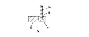
図4は、図3のようにして得られる金属黒鉛質ブラシ42を示し、44はブラシ本体、46は整流子側部材、48はリード線埋込部材である。なおブラシの形状や製造方法自体は任意である。
【0023】
以下に具体的な実施例を示す。ブラシの形状は図1のもので、ブラシ本体4の高さHは13.5mm,長さLは13mm,幅Wは6.5mmである。リード線10はメッキ無しの銅素線の撚り線で、編み線でも良く、直径が3.5mm、埋込部の深さが5.5mmである。整流子側部材6とリード線埋込部材8との高さの比は、例えば3:2程度である。
【0024】
実施例1
天然の鱗状黒鉛100重量部に対し、メタノール40重量部に溶解したノボラック型フェノール樹脂を20重量部混合し、ミキサーで均一に混練し、乾燥機でメタノールを乾燥させた後、衝撃型粉砕器で粉砕し、80メッシュパスの篩(198μmパスの篩)で篩い分けて、樹脂処理黒鉛粉体を得た。この樹脂処理黒鉛粉体37重量部に平均粒径30μmの電解銅粉60重量部、二硫化モリブデン粉3重量部を加えて、V型混合機で均一になるまで混合することにより、整流子側部材6に充填する粉体材料26を得た。また前記の樹脂処理黒鉛30重量部に、平均粒径30μmの電解銅粉70重量部を加えてV型混合機で均一になるまで混合することにより、リード線埋込部材に充填する粉体材料28を得た。これらの粉体材料を、図2のようにして、4×10⁸Pa(4×9800N/cm2)の圧力で一体成形し、還元雰囲気の電気炉で700℃で焼結し、実施例1のブラシを得た。
【0025】
実施例2
実施例1で用いた樹脂処理黒鉛30重量部に、平均粒径30μmの電解銅粉69.5重量部、二硫化モリブデン粉0.5重量部を加えてV型混合機で均一になるまで混合することにより、粉体材料28を得た。整流子側部材の粉体材料26は実施例1と同一とし、他は実施例1と同様にして成形・焼結し、実施例2のブラシを得た。
【0026】
実施例3
実施例1で用いた樹脂処理黒鉛30重量部に、平均粒径30μmの電解銅粉69.2重量部、二硫化モリブデン粉0.8重量部を加えてV型混合機で均一になるまで混合することにより、粉体材料28を得た。粉体材料26は実施例1と同一とし、他は実施例1と同様にして成形・焼結し、実施例3のブラシを得た。
【0027】
比較例1
実施例1で用いた樹脂処理黒鉛35重量部に、平均粒径30μmの電解銅粉60重量部、二硫化モリブデン粉3重量部、鉛粉2重量部を加えてV型混合機で均一になるまで混合することにより、粉体材料を得た。整流子側とリード線埋込部側とで粉体材料を変えずに、ブラシ本体の全体に渡って同じ粉体材料を用い、4×10⁸Paの圧力で成形し、還元雰囲気の電気炉で700℃で焼結し、比較例1のブラシを得た。このブラシは、従来の一般的なブラシ製造方法で製造した鉛入りブラシである。
【0028】
比較例2
実施例1で用いた樹脂処理黒鉛37重量部に、平均粒径30μmの電解銅粉60重量部、二硫化モリブデン粉3重量部を加えて、V型混合機で均一になるまで混合することにより、粉体材料を得た。この粉体材料を比較例1と同様にして成形し、焼結して、比較例2のブラシとした。このブラシは、一般的な方法で製造した鉛無添加のブラシである。
【0029】
比較例3
実施例1で用いた樹脂処理黒鉛30重量部に、平均粒径30μmの電解銅粉68重量部、二硫化モリブデン2重量部を加えてV型混合機で均一になるまで混合して、リード線埋込部材8に充填する粉体材料28を得た。整流子側部材6用の粉体材料26は実施例1と同一とし、他は実施例1と同様にして成形・焼結し、比較例3のブラシを得た。
【0030】
比較例4
実施例1の樹脂処理黒鉛30重量部に平均粒径30μmの電解銅粉67重量部、二硫化モリブデン3重量部を加えてV型混合機で均一になるまで混合して、リード線埋込部材8に充填する粉体材料28を得た。整流子側部材は実施例1と同一とし、他は実施例1と同様の方法で成形、焼結し、比較例4のブラシを得た。
【0031】
上記の各ブラシでの金属硫化物固体潤滑剤の含有量(濃度)は、焼結時にノボラック型フェノール樹脂が一部分解して減量するため、配合濃度に対して計算上は若干増加する。しかし、その増加はほとんど誤差範囲である。表1に実施例1〜3、比較例1〜4における、リード線埋込部材側での金属硫化物固体潤滑剤の含有量を示す。なお、表1中の含有量0%は無添加で実質的に含まないことを示し、不純物の含有量を表すものではない。
【0032】
【表1】
試 料 M o S 2 含有量 (%) 鉛含有量 (%)
実施例1 0 0
実施例2 0.5 0
実施例3 0.8 0
比較例1 3.1 2.0
比較例2 3.1 0
比較例3 2.0 0
比較例4 3.1 0
【0033】
実施例1〜3及び比較例1〜4のブラシを、温度200℃の電気オーブンに入れて強制的に酸化させ、定期的にリード線取付抵抗を測定した。200℃への暴露に伴うリード線取付抵抗の変化を表2に示す。また実施例1〜3及び比較例1〜4のブラシを、温度80℃相対湿度85%の恒温恒湿層に入れ、高湿度に曝して銅を強制的に酸化させて、定期的にリード線取付抵抗を測定した。高湿中でのリード線取付抵抗の変化を表3に示す。測定数は各10個で算術平均値を取った。リード線取付抵抗の測定は、炭素協会規格JCAS−12−1986「電気機械用ブラシのリード線取付抵抗試験方法」に示す方法で行った。
【0034】
【表2】
200℃暴露によるリード線取付抵抗の変化
試料 リード線取付抵抗 (単位 mv/10A)
日数 初期値 1 2 3 4 5 7 10 15
実施例1 0.81 0.83 0.83 0.84 0.85 0.87 0.91 0.99 1.10
実施例2 0.82 0.85 0.86 0.88 0.91 0.93 0.95 1.01 1.12
実施例3 0.83 0.85 0.88 0.90 0.92 0.95 0.98 1.08 1.14
比較例1 0.80 0.82 0.83 0.85 0.86 0.86 0.90 0.98 1.06
比較例2 0.86 0.99 1.12 1.23 1.56 1.62 1.82 1.96 2.02
比較例3 0.82 0.98 1.23 1.31 1.54 1.59 1.78 1.86 2.01
比較例4 0.81 0.89 1.19 1.23 1.42 1.59 1.85 1.96 2.12
【0035】
【表3】
80℃湿度85%暴露によるリード線取付抵抗の変化
試料 リード線取付抵抗 (単位 mv/10A)
日数 初期値 1 2 3 4 5 7 10 15
実施例1 0.79 0.85 0.93 0.98 1.06 1.12 1.23 1.32 1.38
実施例2 0.81 1.12 1.32 1.42 1.63 1.84 1.97 2.23 2.43
実施例3 0.83 1.26 1.54 1.86 2.06 2.56 2.95 3.35 3.62
比較例1 0.80 0.86 0.92 0.99 1.10 1.16 1.21 1.31 1.36
比較例2 0.90 1.02 1.21 1.96 2.68 4.21 6.78 15.43 28.33
比較例3 0.81 1.69 2.55 2.96 3.06 5.12 7.63 14.55 23.56
比較例4 0.81 1.59 3.22 3.65 4.89 6.21 8.55 16.24 25.12
【0036】
比較例1は従来の鉛入りのブラシである。これから鉛を抜いたものが比較例2のブラシであるが、比較例2のブラシは高湿度中でリード線取付抵抗が著しく増大し、高温中でもリード線取付抵抗が増大した。上記の試験は短期間で結果を得るための加速試験であるため、湿度 85%温度80℃という温度の高い暴露条件としているが、高湿条件中では低い温度でもブラシの酸化が進み、長期間の暴露でリード線取付抵抗は同様に上昇する。比較例3はリード線埋込部側に二硫化モリブデンを2重量パーセント添加し、比較例4は3重量パーセント添加したものであるが、比較例2と同様にリード線取付抵抗が大幅に上昇した。
【0037】
実施例1では同様の加速試験を行っても、リード線取付抵抗はほとんど上昇せず、比較例1と同様の結果が得られた。実施例2、実施例3で同様の加速試験を行うと、リード線取付抵抗は実施例1に比べると若干増加したが、ブラシとして使用できないほどではなかった。実施例では、鉛を含有せず、かつ金属硫化物固体潤滑剤を含有するブラシでも、リード線取付抵抗の上昇を防止することができる。実施例は二硫化モリブデンの添加を例にしたが、問題は二硫化モリブデンから生じる硫酸銅などのイオウ化合物であり、二硫化タングステンでも同様である。
【図面の簡単な説明】
【図1】 実施例の金属黒鉛質ブラシの斜視図
【図2】 実施例の金属黒鉛質ブラシの製造工程を模式的に示す図
【図3】 変形例の金属黒鉛質ブラシの製造で、リード線埋込部用の粉体材料を付着させたリード線を、整流子側の粉体材料中に埋め込む工程を模式的に示す図
【図4】 変形例の金属黒鉛質ブラシの断面図
【符号の説明】
2,42 金属黒鉛質ブラシ
4,44 ブラシ本体
6,46 整流子側部材
8,48 リード線埋込部材
10 リード線
12 固定型
14,20 ホッパ
16,18 下部可動型
22 上部可動型
26,28 粉体材料[0001]
[Field of the Invention]
The present invention relates to a metal graphite brush used for an automobile electric motor and the like, and more particularly to lead-free metal graphite brush.
[0002]
[Prior art]
Metallic graphite brushes have been used as low-voltage operation brushes such as automobile electric motor brushes. Metallic graphite brushes are manufactured by mixing graphite, copper powder, and other metal powders, and molding and sintering them. For low-voltage operation, metal powders with lower resistance than graphite are mixed to lower the resistivity. ing. Metal sulfide brushes are often added with metal sulfide solid lubricants such as molybdenum disulfide and tungsten disulfide, and lead. For example, brushes with high loads such as brushes for starter motors are almost always mixed with lead and metal. A sulfide solid lubricant is blended.
[0003]
In recent years, lead has attracted attention as an environmentally hazardous substance, and a brush containing no lead has been demanded. Of course, there are also brushes that do not contain lead, and they have been used for motors other than starter motors. Also, some starter motor brushes can withstand the use even if lead is simply removed under normal operating conditions. Furthermore, in order to improve the lubricity when lead is removed, Japanese Patent Laid-Open No. 5-226048 proposes that a metal having a lower melting point than copper is blended so as not to form an alloy with copper. However, the inventors have found that, in the case of a metal graphite brush in which a metal sulfide solid lubricant is added to copper and graphite, the lead wire mounting resistance increases at high temperatures and high humidity when lead is removed.
[0004]
[Problems of the Invention]
A basic problem of the present invention is to suppress an increase in lead wire attachment resistance at high temperatures and high humidity with respect to a metal-graphite brush that does not contain lead (
[0005]
[Structure of the invention]
The present invention, a material obtained by previously mixing a metal sulfide solid lubricant and the graphite powder and copper powder in the brush body of the shaped fired copper-graphite, the metal graphite brush fitted with a lead wire, lead the brush body In the brush body, a difference in concentration of the metal sulfide solid lubricant is provided between the lead wire embedded portion and the other portion in the brush body, so that the metal sulfide solid lubricant in the lead wire embedded portion The concentration is lower than the concentration of the metal sulfide solid lubricant on the contact portion side with the commutator of the rotating electrical machine, and the concentration (content) of the metal sulfide solid lubricant in the vicinity of the lead wire embedded portion Is characterized by being 1% by weight or less (claim 1).
[0006]
Preferably, the concentration of the metal sulfide solid lubricant is approximately 0% (Claim 2 ). Here, almost 0% means 0.1 wt% or less which is the upper limit of the contamination level of the metal sulfide solid lubricant.
Metal sulfide solid lubricant is preferably at least a member of the group consisting of molybdenum disulfide and tungsten disulfide (claim 3).
Also preferably, the concentration of the metal sulfide solid lubricant at the contact side of the
Also preferably, the copper wires without plating to the lead wire, used as such stranded wire and braid (claim 5).
[0007]
Preferably, the brush body, using different powder materials in the contact portion side and a lead side portion of the commutator is molded integrally (claim 6).
Particularly preferably, the copper concentration on the lead wire embedded portion side is set higher than the copper concentration on the contact portion side with the commutator (claim 7 ).
The type of metallic graphite brush is, for example, a mold brush that is integrally molded by embedding the tip of the lead wire when the brush body is molded.
[0008]
[Operation and effect of the invention]
According to the experiments by the inventors, the increase in the lead wire resistance at high temperatures and high humidity is due to the influence of the metal sulfide solid lubricant. The lead wire mounting resistance did not increase substantially even under high humidity. This is related to the presence or absence of lead. When lead was added, there was almost no increase in lead wire attachment resistance. In addition, in the case of a lead-free brush, the copper powder in the brush body and the embedded lead wire are easily oxidized at high temperatures and high humidity in response to an increase in lead wire attachment resistance.
[0009]
Metal sulfide solid lubricants such as molybdenum disulfide and tungsten disulfide are indispensable for brushes that require a long service life. If no metal sulfide solid lubricant is added, significant wear may occur. In particular, this phenomenon is remarkable in a starter brush or the like to which lead has been conventionally added, and if the lead and the metal sulfide solid lubricant are removed at the same time, the life is remarkably reduced. Therefore, the metal sulfide solid lubricant may not be removed from the lead-free brush.
[0010]
The inventors estimated the mechanism by which the metal sulfide solid lubricant promotes the oxidation of copper powder and embedded lead wires at high temperatures and high humidity as follows. From the metal sulfide solid lubricant added to the brush, sulfur is liberated during sintering and combines with the copper surface to produce copper sulfide. When moisture acts on copper sulfide in high humidity, strongly acidic copper sulfate is generated, and copper powder and lead wires are significantly corroded. Although there are many unclear points in the behavior at high temperatures, it is thought that copper sulfide is oxidized and resistance increases.
[0011]
The mechanism by which lead prevents oxidation of copper powder in the brush and embedded lead wires is not exactly known. The inventors estimate that the lead contained in the brush partially evaporates during sintering and coats the copper surface as a very thin lead layer. This lead layer acts as a protective film, and it is considered that the copper inside the protective film is protected from sulfate ions and the like.
[0012]
In this invention, since the concentration of the metal sulfide solid lubricant in the lead wire embedded portion is made lower than that in other portions, the copper powder in the lead wire and the surrounding brush body is used as the metal sulfide solid lubricant. protected from such derived sulfate ions, it can be prevented or suppressed an increase in the connection resistance of the lead under high temperature or high humidity (claim 1-7).
Further, since different materials are used for the lead wire embedded portion and other portions in the present invention, materials other than the lead wire embedded portion can be freely selected according to requirements such as wear resistance, and a lead-free brush Is easy to design (claims 1 to 7 ).
[0013]
Increase in the lead connection resistance due to the metal sulfide solid lubricant, so significantly in 1 wt.%, 1 weight concentration of the metal sulfide solid lubricant in the vicinity of the lead side portion as in
Of course, if the concentration of the metal sulfide solid lubricant in the lead wire embedded portion is substantially 0%, that is, if the concentration of the metal sulfide solid lubricant is less than the contamination level, it will be in high temperature and high humidity. The increase in the lead wire mounting resistance can be prevented more reliably (claim 2 ).
[0014]
Metal sulfide solid lubricant, etc. lubricity at cost and high temperatures, molybdenum disulfide or tungsten disulfide, or a mixture thereof, preferably (claim 3).
The concentration of the metal sulfide solid lubricant is preferably 1 to 5 percent by weight, and if the concentration is less than 1 percent by weight, sufficient lubrication is not obtained, and if it is 5 percent by weight or more, the resistivity is increased. (Claim 4 ).
[0015]
The lead wire material is not limited to a copper wire, but it is a lead wire using an unplated copper element wire, and prevention of oxidation by a metal sulfide solid lubricant is particularly important (claim 5 ). In addition, with a brush, the lead wire is also sintered together with the brush body at the time of sintering. Therefore, even if the lead wire is plated with silver or nickel on the surface of the copper lead wire, Copper must be alloyed with the plating material and diffuse to the surface, preventing oxidation.
[0016]
From ease of manufacturing, divide the brush body into two members of the attachment portion side of the contact portion and the lead wire of the commutator is preferably molded integrally using different powder materials (claim 6 ).
Here, it is preferable to increase the copper concentration in the brush material on the lead wire attachment portion side than on the commutator side, since the lead wire attachment resistance is reduced (claim 7 ).
[0017]
Even in the case of a lead-free brush, the electrolytic copper powder generally used for metal graphite brushes often contains lead as an impurity for manufacturing reasons. Further, in the brush manufacturing process, when a lead-free brush and a lead-added brush are manufactured using the same equipment, a small amount of lead enters the lead-free brush as a contamination. However, in a lead-free brush, the lead concentration in the brush body generally does not exceed 0.2% by weight. Similarly, if a metal sulfide solid lubricant such as molybdenum disulfide or tungsten disulfide is added, contamination in the manufacturing process is unavoidable as with lead, and a small amount of metal sulfide solid lubricant is not attached to the lead wire mounting part. It may be included in the vicinity. However, in the case of contamination, the concentration of the metal sulfide solid lubricant in the vicinity of the lead wire attachment portion does not exceed 0.1% by weight.
[0018]
【Example】
1 to 4 show a brush structure and a manufacturing method. FIG. 1 shows a
[0019]
The commutator side member 6 and the lead wire embedding member 8 have different metal sulfide solid lubricant concentrations, and the lead wire embedding member 8 has at least 1 wt% or less, preferably no additive. When the boundary between the commutator side member 6 and the lead wire embedding member 8 is unclear, for example, the
[0020]
For example, the
[0021]
FIG. 3 shows the manufacture of a modified brush, and a commutator-side
[0022]
4 shows a
[0023]
Specific examples are shown below. The shape of the brush is that shown in FIG. 1. The
[0024]
Example 1
20 parts by weight of novolac type phenol resin dissolved in 40 parts by weight of methanol is mixed with 100 parts by weight of natural scaly graphite, uniformly kneaded with a mixer, dried with a drier, and then with an impact type grinder. The resultant was pulverized and sieved with an 80 mesh pass sieve (198 μm pass sieve) to obtain a resin-treated graphite powder. By adding 60 parts by weight of electrolytic copper powder with an average particle size of 30 μm and 3 parts by weight of molybdenum disulfide powder to 37 parts by weight of this resin-treated graphite powder, mixing until uniform with a V-type mixer, the commutator side
[0025]
Example 2
Add 69.5 parts by weight of electrolytic copper powder with an average particle size of 30 μm and 0.5 parts by weight of molybdenum disulfide powder to 30 parts by weight of the resin-treated graphite used in Example 1, and mix until uniform with a V-type mixer. As a result, a
[0026]
Example 3
Add 69.2 parts by weight of electrolytic copper powder having an average particle size of 30 μm and 0.8 part by weight of molybdenum disulfide powder to 30 parts by weight of resin-treated graphite used in Example 1, and mix until uniform using a V-type mixer. As a result, a
[0027]
Comparative Example 1
Addition of 60 parts by weight of electrolytic copper powder having an average particle size of 30 μm, 3 parts by weight of molybdenum disulfide powder, and 2 parts by weight of lead powder to 35 parts by weight of the resin-treated graphite used in Example 1, and uniform in a V-type mixer To obtain a powder material. The same powder material is used throughout the brush body without changing the powder material on the commutator side and the lead wire embedding side, and is molded at a pressure of 4 × 10 8 Pa. Was sintered at 700 ° C. to obtain a brush of Comparative Example 1. This brush is a lead-containing brush manufactured by a conventional general brush manufacturing method.
[0028]
Comparative Example 2
By adding 60 parts by weight of electrolytic copper powder having an average particle size of 30 μm and 3 parts by weight of molybdenum disulfide powder to 37 parts by weight of the resin-treated graphite used in Example 1, and mixing them with a V-type mixer until uniform. A powder material was obtained. This powder material was molded and sintered in the same manner as in Comparative Example 1 to obtain a brush of Comparative Example 2. This brush is a lead-free brush manufactured by a general method.
[0029]
Comparative Example 3
Add 68 parts by weight of electrolytic copper powder with an average particle size of 30 μm and 2 parts by weight of molybdenum disulfide to 30 parts by weight of the resin-treated graphite used in Example 1, and mix them until uniform using a V-type mixer. A
[0030]
Comparative Example 4
A lead wire embedding member was prepared by adding 67 parts by weight of electrolytic copper powder having an average particle size of 30 μm and 3 parts by weight of molybdenum disulfide to 30 parts by weight of the resin-treated graphite of Example 1, and mixing them with a V-type mixer until uniform. 8 was obtained. The commutator side member was the same as in Example 1, and the others were molded and sintered in the same manner as in Example 1 to obtain the brush of Comparative Example 4.
[0031]
The content (concentration) of the metal sulfide solid lubricant in each of the brushes described above slightly increases in calculation with respect to the blending concentration because the novolac type phenol resin is partially decomposed and reduced during sintering. However, the increase is almost in error. Table 1 shows the content of the metal sulfide solid lubricant on the lead wire embedded member side in Examples 1 to 3 and Comparative Examples 1 to 4. In Table 1, the content of 0% indicates that it is not added and is not substantially contained, and does not represent the content of impurities.
[0032]
[Table 1]
Specimen
Example 1 0 0
Example 2 0.5 0
Example 3 0.8 0
Comparative Example 1 3.1 2.0
Comparative Example 2 3.1 0
Comparative Example 3 2.0 0
Comparative Example 4 3.1 0
[0033]
The brushes of Examples 1 to 3 and Comparative Examples 1 to 4 were put into an electric oven at a temperature of 200 ° C. to forcibly oxidize, and the lead wire attachment resistance was measured periodically. Table 2 shows the change in lead wire attachment resistance with exposure to 200 ° C. Further, the brushes of Examples 1 to 3 and Comparative Examples 1 to 4 are placed in a constant temperature and humidity layer at a temperature of 80 ° C. and a relative humidity of 85%, and exposed to high humidity to forcibly oxidize copper and periodically lead wires. The mounting resistance was measured. Table 3 shows changes in the lead wire attachment resistance in high humidity. The number of measurements was 10 for each, and the arithmetic average value was taken. The measurement of lead wire attachment resistance was performed by the method shown in Carbon Society Standard JCAS-12-1986 “Test Method for Lead Wire Attachment Resistance of Brushes for Electric Machines”.
[0034]
[Table 2]
Change in lead wire mounting resistance due to exposure at 200 ℃ Sample Lead wire mounting resistance (Unit: mv / 10A)
Days
Example 1 0.81 0.83 0.83 0.84 0.85 0.87 0.91 0.99 1.10
Example 2 0.82 0.85 0.86 0.88 0.91 0.93 0.95 1.01 1.12
Example 3 0.83 0.85 0.88 0.90 0.92 0.95 0.98 1.08 1.14
Comparative Example 1 0.80 0.82 0.83 0.85 0.86 0.86 0.90 0.98 1.06
Comparative Example 2 0.86 0.99 1.12 1.23 1.56 1.62 1.82 1.96 2.02
Comparative Example 3 0.82 0.98 1.23 1.31 1.54 1.59 1.78 1.86 2.01
Comparative Example 4 0.81 0.89 1.19 1.23 1.42 1.59 1.85 1.96 2.12
[0035]
[Table 3]
Change in lead wire mounting resistance due to exposure to 80 ° C and humidity 85% Sample Lead wire mounting resistance (Unit: mv / 10A)
Days
Example 1 0.79 0.85 0.93 0.98 1.06 1.12 1.23 1.32 1.38
Example 2 0.81 1.12 1.32 1.42 1.63 1.84 1.97 2.23 2.43
Example 3 0.83 1.26 1.54 1.86 2.06 2.56 2.95 3.35 3.62
Comparative Example 1 0.80 0.86 0.92 0.99 1.10 1.16 1.21 1.31 1.36
Comparative Example 2 0.90 1.02 1.21 1.96 2.68 4.21 6.78 15.43 28.33
Comparative Example 3 0.81 1.69 2.55 2.96 3.06 5.12 7.63 14.55 23.56
Comparative Example 4 0.81 1.59 3.22 3.65 4.89 6.21 8.55 16.24 25.12
[0036]
Comparative Example 1 is a conventional lead-containing brush. The brush from which the lead is removed is the brush of Comparative Example 2. However, the brush of Comparative Example 2 has a remarkably increased lead wire attachment resistance at high humidity and an increased lead wire attachment resistance even at high temperatures. Since the above test is an accelerated test for obtaining results in a short period of time, the exposure conditions are high at a humidity of 85% and a temperature of 80 ° C. As a result of the exposure, the lead wire mounting resistance similarly increases. In Comparative Example 3, 2% by weight of molybdenum disulfide was added to the lead wire embedded portion side, and in Comparative Example 4, 3% by weight was added. However, as in Comparative Example 2, the lead wire mounting resistance increased significantly. .
[0037]
In Example 1, even when the same acceleration test was performed, the lead wire attachment resistance hardly increased, and the same result as in Comparative Example 1 was obtained. When the same acceleration test was performed in Example 2 and Example 3, the lead wire attachment resistance increased slightly compared to Example 1, but not so much that it could not be used as a brush. In the embodiment, even with a brush that does not contain lead and contains a metal sulfide solid lubricant, an increase in lead wire mounting resistance can be prevented. In the examples, addition of molybdenum disulfide was taken as an example, but the problem is a sulfur compound such as copper sulfate produced from molybdenum disulfide, and the same applies to tungsten disulfide.
[Brief description of the drawings]
FIG. 1 is a perspective view of a metal graphite brush of an example. FIG. 2 is a diagram schematically showing a manufacturing process of the metal graphite brush of the example. FIG. Diagram showing the process of embedding the lead wire with the powder material for the wire embedding part in the commutator side powder material. [Fig. 4] Cross section of the modified metal graphite brush Explanation of]
2, 42 Metallic graphite brushes 4, 44
Claims (7)
前記ブラシ本体を鉛無添加とし、
前記ブラシ本体には、前記リード線の埋込部と他の部分とで金属硫化物固体潤滑剤の濃度差を設けて、リード線の埋込部近傍での金属硫化物固体潤滑剤の濃度を、回転電機の整流子との接触部側での金属硫化物固体潤滑剤の濃度よりも低くし、リード線の埋込部近傍での金属硫化物固体潤滑剤の濃度を1重量%以下としたことを特徴とする、金属黒鉛質ブラシ。 In a metal graphite brush with lead wires embedded in a copper graphite brush body formed and fired by premixing a metal sulfide solid lubricant, graphite powder and copper powder ,
The brush body has no lead added,
The brush body is provided with a difference in the concentration of the metal sulfide solid lubricant between the embedded portion of the lead wire and the other portion, and the concentration of the metal sulfide solid lubricant in the vicinity of the embedded portion of the lead wire is set. The concentration of the metal sulfide solid lubricant in the vicinity of the contact portion with the commutator of the rotating electrical machine is lower than the concentration of the metal sulfide solid lubricant in the vicinity of the lead wire embedded portion. A metallic graphite brush characterized by the above.
Priority Applications (6)
| Application Number | Priority Date | Filing Date | Title |
|---|---|---|---|
| JP2001327537A JP3661784B2 (en) | 2001-10-25 | 2001-10-25 | Metal graphite brush |
| EP02023827A EP1306936B1 (en) | 2001-10-25 | 2002-10-23 | Metal-graphite brush |
| DE60222518T DE60222518T2 (en) | 2001-10-25 | 2002-10-23 | Metal graphite brush |
| AT02023827T ATE373884T1 (en) | 2001-10-25 | 2002-10-23 | METAL-GRAPHITE BRUSH |
| KR1020020065135A KR100729482B1 (en) | 2001-10-25 | 2002-10-24 | Metal-Graphite Brush |
| US10/279,776 US7294166B2 (en) | 2001-10-25 | 2002-10-24 | Metal-graphite brush |
Applications Claiming Priority (1)
| Application Number | Priority Date | Filing Date | Title |
|---|---|---|---|
| JP2001327537A JP3661784B2 (en) | 2001-10-25 | 2001-10-25 | Metal graphite brush |
Publications (2)
| Publication Number | Publication Date |
|---|---|
| JP2003134742A JP2003134742A (en) | 2003-05-09 |
| JP3661784B2 true JP3661784B2 (en) | 2005-06-22 |
Family
ID=19143755
Family Applications (1)
| Application Number | Title | Priority Date | Filing Date |
|---|---|---|---|
| JP2001327537A Expired - Lifetime JP3661784B2 (en) | 2001-10-25 | 2001-10-25 | Metal graphite brush |
Country Status (6)
| Country | Link |
|---|---|
| US (1) | US7294166B2 (en) |
| EP (1) | EP1306936B1 (en) |
| JP (1) | JP3661784B2 (en) |
| KR (1) | KR100729482B1 (en) |
| AT (1) | ATE373884T1 (en) |
| DE (1) | DE60222518T2 (en) |
Families Citing this family (2)
| Publication number | Priority date | Publication date | Assignee | Title |
|---|---|---|---|---|
| DE102006006313B4 (en) * | 2006-02-08 | 2008-05-21 | Schunk Kohlenstofftechnik Gmbh | Method and device for producing a multilayer molded article |
| JP6148593B2 (en) * | 2013-10-16 | 2017-06-14 | アスモ株式会社 | Rotating electric machine |
Family Cites Families (14)
| Publication number | Priority date | Publication date | Assignee | Title |
|---|---|---|---|---|
| GB836984A (en) * | 1955-07-09 | 1960-06-09 | Morgan Crucible Co | Electric current collecting brushes and collectors |
| US2777081A (en) * | 1955-10-07 | 1957-01-08 | Westinghouse Electric Corp | Electrical brush and dynamoelectric apparatus embodying the same |
| US3302270A (en) * | 1962-11-09 | 1967-02-07 | Photocircuits Corp | Method of wear-resistant coating a commutator contact surface |
| US3300667A (en) | 1963-11-04 | 1967-01-24 | Westinghouse Electric Corp | Electrically conductive solid lubricant members and process and apparatus employing them |
| US3303370A (en) | 1963-11-04 | 1967-02-07 | Westinghouse Electric Corp | Electrically conductive solid lubricant members and process and apparatus employing them |
| FR1421506A (en) * | 1964-11-03 | 1965-12-17 | Westinghouse Electric Corp | Solid lubricating, electrically conductive elements, method of manufacture and apparatus using such elements |
| GB1259454A (en) * | 1968-05-23 | 1972-01-05 | ||
| JPS5556795A (en) | 1978-10-24 | 1980-04-25 | Tokyo Hoso:Kk | Luminance correction circuit |
| JPS6042595B2 (en) * | 1981-09-22 | 1985-09-24 | 富士化工株式会社 | electric brush |
| JPS58121582A (en) * | 1982-01-14 | 1983-07-19 | 日立化成工業株式会社 | Method of producing brush |
| DE59105627D1 (en) | 1991-07-22 | 1995-07-06 | Carbone Ag | Sliding contact piece for high current densities. |
| JP3451742B2 (en) * | 1994-09-27 | 2003-09-29 | 株式会社デンソー | Electric brush and manufacturing method thereof |
| JP3428915B2 (en) | 1998-11-11 | 2003-07-22 | 株式会社日鉱マテリアルズ | Mixed powder for powder metallurgy, powder metallurgy sintered body and method for producing the same |
| JP3929746B2 (en) * | 2001-10-25 | 2007-06-13 | トライス株式会社 | Metal graphite brush |
-
2001
- 2001-10-25 JP JP2001327537A patent/JP3661784B2/en not_active Expired - Lifetime
-
2002
- 2002-10-23 AT AT02023827T patent/ATE373884T1/en not_active IP Right Cessation
- 2002-10-23 DE DE60222518T patent/DE60222518T2/en not_active Expired - Lifetime
- 2002-10-23 EP EP02023827A patent/EP1306936B1/en not_active Expired - Lifetime
- 2002-10-24 KR KR1020020065135A patent/KR100729482B1/en active IP Right Grant
- 2002-10-24 US US10/279,776 patent/US7294166B2/en active Active
Also Published As
| Publication number | Publication date |
|---|---|
| DE60222518D1 (en) | 2007-10-31 |
| KR100729482B1 (en) | 2007-06-15 |
| US7294166B2 (en) | 2007-11-13 |
| DE60222518T2 (en) | 2008-06-12 |
| EP1306936A3 (en) | 2004-07-21 |
| US20060087197A1 (en) | 2006-04-27 |
| JP2003134742A (en) | 2003-05-09 |
| EP1306936A2 (en) | 2003-05-02 |
| KR20030034017A (en) | 2003-05-01 |
| EP1306936B1 (en) | 2007-09-19 |
| ATE373884T1 (en) | 2007-10-15 |
Similar Documents
| Publication | Publication Date | Title |
|---|---|---|
| EP1315254B1 (en) | Carbon brush for electric machine | |
| KR100729484B1 (en) | Metal-Graphite Brush and Production Method thereof | |
| JP3770476B2 (en) | Metal graphite brush | |
| JP3929746B2 (en) | Metal graphite brush | |
| JP3797662B2 (en) | Copper graphite brush | |
| JP4512318B2 (en) | Laminated brush | |
| JP3661784B2 (en) | Metal graphite brush | |
| KR100708030B1 (en) | Metal-Graphite Brush | |
| JP2001327127A (en) | Copper-carbon brush and its manufacturing method | |
| JP2007060859A (en) | Brush | |
| JP2003259606A (en) | Metallic graphite brush | |
| JP2006320067A (en) | Process of metal graphite brush | |
| JP2005304115A (en) | Metal graphite brush | |
| JP2006320043A (en) | Metal graphite brush | |
| JP2007028840A (en) | Brush |
Legal Events
| Date | Code | Title | Description |
|---|---|---|---|
| A621 | Written request for application examination |
Free format text: JAPANESE INTERMEDIATE CODE: A621 Effective date: 20040304 |
|
| A977 | Report on retrieval |
Free format text: JAPANESE INTERMEDIATE CODE: A971007 Effective date: 20041021 |
|
| A131 | Notification of reasons for refusal |
Free format text: JAPANESE INTERMEDIATE CODE: A131 Effective date: 20041025 |
|
| A521 | Request for written amendment filed |
Free format text: JAPANESE INTERMEDIATE CODE: A523 Effective date: 20041221 |
|
| TRDD | Decision of grant or rejection written | ||
| A01 | Written decision to grant a patent or to grant a registration (utility model) |
Free format text: JAPANESE INTERMEDIATE CODE: A01 Effective date: 20050217 |
|
| A61 | First payment of annual fees (during grant procedure) |
Free format text: JAPANESE INTERMEDIATE CODE: A61 Effective date: 20050315 |
|
| R150 | Certificate of patent or registration of utility model |
Ref document number: 3661784 Country of ref document: JP Free format text: JAPANESE INTERMEDIATE CODE: R150 Free format text: JAPANESE INTERMEDIATE CODE: R150 |
|
| FPAY | Renewal fee payment (event date is renewal date of database) |
Free format text: PAYMENT UNTIL: 20080401 Year of fee payment: 3 |
|
| FPAY | Renewal fee payment (event date is renewal date of database) |
Free format text: PAYMENT UNTIL: 20090401 Year of fee payment: 4 |
|
| R250 | Receipt of annual fees |
Free format text: JAPANESE INTERMEDIATE CODE: R250 |
|
| FPAY | Renewal fee payment (event date is renewal date of database) |
Free format text: PAYMENT UNTIL: 20090401 Year of fee payment: 4 |
|
| FPAY | Renewal fee payment (event date is renewal date of database) |
Free format text: PAYMENT UNTIL: 20100401 Year of fee payment: 5 |
|
| R250 | Receipt of annual fees |
Free format text: JAPANESE INTERMEDIATE CODE: R250 |
|
| FPAY | Renewal fee payment (event date is renewal date of database) |
Free format text: PAYMENT UNTIL: 20100401 Year of fee payment: 5 |
|
| FPAY | Renewal fee payment (event date is renewal date of database) |
Free format text: PAYMENT UNTIL: 20110401 Year of fee payment: 6 |
|
| R250 | Receipt of annual fees |
Free format text: JAPANESE INTERMEDIATE CODE: R250 |
|
| FPAY | Renewal fee payment (event date is renewal date of database) |
Free format text: PAYMENT UNTIL: 20110401 Year of fee payment: 6 |
|
| FPAY | Renewal fee payment (event date is renewal date of database) |
Free format text: PAYMENT UNTIL: 20120401 Year of fee payment: 7 |
|
| R250 | Receipt of annual fees |
Free format text: JAPANESE INTERMEDIATE CODE: R250 |
|
| FPAY | Renewal fee payment (event date is renewal date of database) |
Free format text: PAYMENT UNTIL: 20130401 Year of fee payment: 8 |
|
| R250 | Receipt of annual fees |
Free format text: JAPANESE INTERMEDIATE CODE: R250 |
|
| FPAY | Renewal fee payment (event date is renewal date of database) |
Free format text: PAYMENT UNTIL: 20130401 Year of fee payment: 8 |
|
| R250 | Receipt of annual fees |
Free format text: JAPANESE INTERMEDIATE CODE: R250 |
|
| R250 | Receipt of annual fees |
Free format text: JAPANESE INTERMEDIATE CODE: R250 |
|
| R250 | Receipt of annual fees |
Free format text: JAPANESE INTERMEDIATE CODE: R250 |
|
| R250 | Receipt of annual fees |
Free format text: JAPANESE INTERMEDIATE CODE: R250 |
|
| R250 | Receipt of annual fees |
Free format text: JAPANESE INTERMEDIATE CODE: R250 |
|
| R250 | Receipt of annual fees |
Free format text: JAPANESE INTERMEDIATE CODE: R250 |
|
| R250 | Receipt of annual fees |
Free format text: JAPANESE INTERMEDIATE CODE: R250 |
|
| R250 | Receipt of annual fees |
Free format text: JAPANESE INTERMEDIATE CODE: R250 |
|
| R250 | Receipt of annual fees |
Free format text: JAPANESE INTERMEDIATE CODE: R250 |
|
| EXPY | Cancellation because of completion of term |