JP3661133B2 - Rolling bearing for compressor - Google Patents
Rolling bearing for compressor Download PDFInfo
- Publication number
- JP3661133B2 JP3661133B2 JP17546495A JP17546495A JP3661133B2 JP 3661133 B2 JP3661133 B2 JP 3661133B2 JP 17546495 A JP17546495 A JP 17546495A JP 17546495 A JP17546495 A JP 17546495A JP 3661133 B2 JP3661133 B2 JP 3661133B2
- Authority
- JP
- Japan
- Prior art keywords
- cage
- treatment
- bearing
- layer
- rolling
- Prior art date
- Legal status (The legal status is an assumption and is not a legal conclusion. Google has not performed a legal analysis and makes no representation as to the accuracy of the status listed.)
- Expired - Fee Related
Links
Images


Classifications
-
- F—MECHANICAL ENGINEERING; LIGHTING; HEATING; WEAPONS; BLASTING
- F16—ENGINEERING ELEMENTS AND UNITS; GENERAL MEASURES FOR PRODUCING AND MAINTAINING EFFECTIVE FUNCTIONING OF MACHINES OR INSTALLATIONS; THERMAL INSULATION IN GENERAL
- F16C—SHAFTS; FLEXIBLE SHAFTS; ELEMENTS OR CRANKSHAFT MECHANISMS; ROTARY BODIES OTHER THAN GEARING ELEMENTS; BEARINGS
- F16C33/00—Parts of bearings; Special methods for making bearings or parts thereof
- F16C33/30—Parts of ball or roller bearings
- F16C33/66—Special parts or details in view of lubrication
- F16C33/6696—Special parts or details in view of lubrication with solids as lubricant, e.g. dry coatings, powder
-
- C—CHEMISTRY; METALLURGY
- C23—COATING METALLIC MATERIAL; COATING MATERIAL WITH METALLIC MATERIAL; CHEMICAL SURFACE TREATMENT; DIFFUSION TREATMENT OF METALLIC MATERIAL; COATING BY VACUUM EVAPORATION, BY SPUTTERING, BY ION IMPLANTATION OR BY CHEMICAL VAPOUR DEPOSITION, IN GENERAL; INHIBITING CORROSION OF METALLIC MATERIAL OR INCRUSTATION IN GENERAL
- C23C—COATING METALLIC MATERIAL; COATING MATERIAL WITH METALLIC MATERIAL; SURFACE TREATMENT OF METALLIC MATERIAL BY DIFFUSION INTO THE SURFACE, BY CHEMICAL CONVERSION OR SUBSTITUTION; COATING BY VACUUM EVAPORATION, BY SPUTTERING, BY ION IMPLANTATION OR BY CHEMICAL VAPOUR DEPOSITION, IN GENERAL
- C23C22/00—Chemical surface treatment of metallic material by reaction of the surface with a reactive liquid, leaving reaction products of surface material in the coating, e.g. conversion coatings, passivation of metals
- C23C22/05—Chemical surface treatment of metallic material by reaction of the surface with a reactive liquid, leaving reaction products of surface material in the coating, e.g. conversion coatings, passivation of metals using aqueous solutions
- C23C22/06—Chemical surface treatment of metallic material by reaction of the surface with a reactive liquid, leaving reaction products of surface material in the coating, e.g. conversion coatings, passivation of metals using aqueous solutions using aqueous acidic solutions with pH less than 6
- C23C22/07—Chemical surface treatment of metallic material by reaction of the surface with a reactive liquid, leaving reaction products of surface material in the coating, e.g. conversion coatings, passivation of metals using aqueous solutions using aqueous acidic solutions with pH less than 6 containing phosphates
- C23C22/08—Orthophosphates
- C23C22/18—Orthophosphates containing manganese cations
-
- C—CHEMISTRY; METALLURGY
- C23—COATING METALLIC MATERIAL; COATING MATERIAL WITH METALLIC MATERIAL; CHEMICAL SURFACE TREATMENT; DIFFUSION TREATMENT OF METALLIC MATERIAL; COATING BY VACUUM EVAPORATION, BY SPUTTERING, BY ION IMPLANTATION OR BY CHEMICAL VAPOUR DEPOSITION, IN GENERAL; INHIBITING CORROSION OF METALLIC MATERIAL OR INCRUSTATION IN GENERAL
- C23C—COATING METALLIC MATERIAL; COATING MATERIAL WITH METALLIC MATERIAL; SURFACE TREATMENT OF METALLIC MATERIAL BY DIFFUSION INTO THE SURFACE, BY CHEMICAL CONVERSION OR SUBSTITUTION; COATING BY VACUUM EVAPORATION, BY SPUTTERING, BY ION IMPLANTATION OR BY CHEMICAL VAPOUR DEPOSITION, IN GENERAL
- C23C22/00—Chemical surface treatment of metallic material by reaction of the surface with a reactive liquid, leaving reaction products of surface material in the coating, e.g. conversion coatings, passivation of metals
- C23C22/82—After-treatment
- C23C22/83—Chemical after-treatment
-
- F—MECHANICAL ENGINEERING; LIGHTING; HEATING; WEAPONS; BLASTING
- F16—ENGINEERING ELEMENTS AND UNITS; GENERAL MEASURES FOR PRODUCING AND MAINTAINING EFFECTIVE FUNCTIONING OF MACHINES OR INSTALLATIONS; THERMAL INSULATION IN GENERAL
- F16C—SHAFTS; FLEXIBLE SHAFTS; ELEMENTS OR CRANKSHAFT MECHANISMS; ROTARY BODIES OTHER THAN GEARING ELEMENTS; BEARINGS
- F16C19/00—Bearings with rolling contact, for exclusively rotary movement
- F16C19/22—Bearings with rolling contact, for exclusively rotary movement with bearing rollers essentially of the same size in one or more circular rows, e.g. needle bearings
- F16C19/30—Bearings with rolling contact, for exclusively rotary movement with bearing rollers essentially of the same size in one or more circular rows, e.g. needle bearings for axial load mainly
-
- F—MECHANICAL ENGINEERING; LIGHTING; HEATING; WEAPONS; BLASTING
- F16—ENGINEERING ELEMENTS AND UNITS; GENERAL MEASURES FOR PRODUCING AND MAINTAINING EFFECTIVE FUNCTIONING OF MACHINES OR INSTALLATIONS; THERMAL INSULATION IN GENERAL
- F16C—SHAFTS; FLEXIBLE SHAFTS; ELEMENTS OR CRANKSHAFT MECHANISMS; ROTARY BODIES OTHER THAN GEARING ELEMENTS; BEARINGS
- F16C33/00—Parts of bearings; Special methods for making bearings or parts thereof
- F16C33/30—Parts of ball or roller bearings
- F16C33/46—Cages for rollers or needles
- F16C33/54—Cages for rollers or needles made from wire, strips, or sheet metal
- F16C33/542—Cages for rollers or needles made from wire, strips, or sheet metal made from sheet metal
- F16C33/543—Cages for rollers or needles made from wire, strips, or sheet metal made from sheet metal from a single part
-
- F—MECHANICAL ENGINEERING; LIGHTING; HEATING; WEAPONS; BLASTING
- F16—ENGINEERING ELEMENTS AND UNITS; GENERAL MEASURES FOR PRODUCING AND MAINTAINING EFFECTIVE FUNCTIONING OF MACHINES OR INSTALLATIONS; THERMAL INSULATION IN GENERAL
- F16C—SHAFTS; FLEXIBLE SHAFTS; ELEMENTS OR CRANKSHAFT MECHANISMS; ROTARY BODIES OTHER THAN GEARING ELEMENTS; BEARINGS
- F16C33/00—Parts of bearings; Special methods for making bearings or parts thereof
- F16C33/30—Parts of ball or roller bearings
- F16C33/46—Cages for rollers or needles
- F16C33/56—Selection of substances
- F16C33/565—Coatings
-
- Y—GENERAL TAGGING OF NEW TECHNOLOGICAL DEVELOPMENTS; GENERAL TAGGING OF CROSS-SECTIONAL TECHNOLOGIES SPANNING OVER SEVERAL SECTIONS OF THE IPC; TECHNICAL SUBJECTS COVERED BY FORMER USPC CROSS-REFERENCE ART COLLECTIONS [XRACs] AND DIGESTS
- Y10—TECHNICAL SUBJECTS COVERED BY FORMER USPC
- Y10S—TECHNICAL SUBJECTS COVERED BY FORMER USPC CROSS-REFERENCE ART COLLECTIONS [XRACs] AND DIGESTS
- Y10S384/00—Bearings
- Y10S384/90—Cooling or heating
- Y10S384/913—Metallic compounds
Description
【0001】
【産業上の利用分野】
本発明は、スラスト針状コロ軸受、転がり軸受、およびスラスト針状コロ軸受の保持器に関し、特に代替フロン等の環境下で使用するのに好適なスラスト針状コロ軸受、転がり軸受、およびスラスト針状コロ軸受の保持器に関する。
【0002】
【従来の技術】
従来、スラスト針状コロ軸受は、保持器と針状コロで構成されており、また、これらと軌道輪を組み合わせたものも知られており、針状コロとしては、通常、コロの径(Da)と、コロの長さ(lr)の比(lr/Da)が1.4〜3.4程度のものが使用されている。
【0003】
また、近年、地球温暖化防止等の環境保護の観点から、エアコン用のコンプレッサ等においても、冷媒としてHCFC134a等の代替フロンの使用が開始されている。この代替フロンは、従来のCFC(クロロフルオロカーボン)12等に比べて、自己潤滑作用が乏しいだけでなく、相溶性の観点から作動油として用いられるPAG(ポリアリキレングリコール)は、吸湿性が大きいという特徴がある。
【0004】
このため、代替フロンとPAGの環境の下で軸受を使用した場合、PAG中に侵入した微量の水分により微小ピットが発生し、さらに吸水および代替フロンの溶解によりPAGの粘度が低下して潤滑条件が劣化する等の複合的作用により、剥離、摩耗等の表面損傷を生じて軸受けが焼き付いてしまい、所期の寿命特性が得られないという問題が生じる。
【0005】
このような問題を解決するためには、軸受材料の耐食性を向上させ、さらに潤滑条件の改善を図る必要がある。そこで、従来は、耐食性の向上方法としては、軸受材料としてステンレス鋼(例えばSUS440C)を使用するのが一般的である。また、潤滑条件の改善に関しては、作動油を改良して潤滑性を改善するのが最も効果があるが、相溶性の観点から作動油の選択範囲が制限されることから大幅な潤滑性の向上は望めない。
【0006】
そこで、冷媒中の潤滑油の量を増やして潤滑性を向上させることにより焼き付けを防止する方法が考えられるが、この方法では、コンプレッサの冷却性能が劣化するという新たな問題が生じる。この新たな問題点を解決する技術としては、保持器の表面処理、すなわち基板上にフッ化炭素化合物のプラズマ重合層を形成することによって焼き付けを防止するようにしたものが知られている(特開平2−238094号公報)。
【0007】
また、従来、軸受の転動体を保持する保持器の材質としては、金属が使用されてきたが、金属製の保持器では、転動体との間で摩耗が生じやすく、寿命が短くなるため、特開昭第64−79419号公報、特開平第4−357323号公報に開示されている通り、樹脂製の保持器が実現されている。なお、これら樹脂製の保持器はその全ての部分が樹脂により構成されている。
【0008】
【発明が解決しようとする課題】
ところで、スラスト針状コロ軸受において、動トルクを小さくするためにはコロの長さを短くすればよいが、あまり短くするとコロの姿勢が不安定になったり、コロが保持器から脱落したり、研削加工が困難になるという問題が生じる。
【0009】
また、耐食性を向上させるために、軸受材料としてステンレス鋼を使用すると、軸受のコストが上昇し、車載用のコンプレッサに適用するのが困難になるという問題があった。また、上記のように、作動油の改良による潤滑条件の改善は、十分な効果が得られていないという問題もあった。さらに、上記公報の表面処理(プラズマ重合層の形成)は、量産に適さず製造コストのアップを招くと共に、基板のような平面に対しては均一に表面処理を行えるが、軸受保持器のような複雑な形状のものに対しては、均一に表面処理を行えないという問題があった。
【0010】
また、保持器を金属で構成すると、転動体(コロ)との間で摩耗が生じやすく、寿命が短くなるという問題を解決すべく、保持器の全ての部分を樹脂で構成すると、金属で構成した場合に比べて剛性が弱くなってしまう。このため、特に、スラスト針状コロ軸受では、転動体間の間仕切り部(柱部)や転動体の端面を受ける外周部の厚さが非常に薄いので、高速で回転する転動体の遠心力によりクリープ変形を起こすという新たな問題が生じていた。
【0011】
本発明は、このような背景の下になされたもので、その目的は、代替フロン、水混入潤滑油の環境下でも、安価に耐摩耗性および潤滑条件を向上できるようにすることにある。
【0014】
【課題を解決するための手段】
上記目的を達成するため、本発明は、外輪と内輪との間に配設された複数の転動体を等間隔に隔てる保持器を有するコンプレッサ用転がり軸受において、前記保持器の表面に第1層として燐酸塩被膜を4〜10μm施し、その上の第2層として、固体潤滑材被膜を2〜30μm形成し、前記第1層の燐酸塩被膜の下地として浸炭窒化層を有し、前記外輪、内輪、転動体の少なくとも1つの転動面に浸炭窒化処理による浸炭窒化層を有し、前記浸炭窒化層の窒素濃度が0.08〜0.5%となっている。
【0017】
【作用】
本発明に係るコンプレッサ用転がり軸受では、保持器の表面に第1層として燐酸塩被膜を1〜10μm施し、その上の第2層として固体潤滑材被膜を2〜30μm形成し、前記第1層の燐酸塩被膜の下地として浸炭窒化層を有し、外輪、内輪、転動体の少なくとも1つの転動面に浸炭窒化処理による浸炭窒化層を有し、浸炭窒化層の窒素濃度が0.08〜0.5%となっているので、代替フロン、水混入潤滑油の環境下でも、安価に耐摩耗性および潤滑条件を向上させて焼付けの発生が遅延され、コンプレッサ用転がり軸受の長寿命化が達成されるようになる。
【0020】
【実施例】
[第1の発明の実施例]
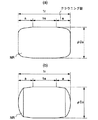
図1は第1の発明の実施例によるスラスト針状コロ軸受の針状コロの形状を示す図である。図1(a),(b)に示したように、第1の発明では、長さlrの針状コロNRに対して、その両端部分に長さaのクラウニングを形成することにより、相手軌道面との接触長さlaが全長lrの3/4以下とし、これによりスラスト針状コロ軸受の動トルクを低減している。なお、図1(b)に示したように、針状コロNRの両端面をアーチ状にすることにより、針状コロNRの両端面と保持器との接触面積を小さくして、より動トルクを低減することも可能である。
【0021】
また、第1の発明では、針状コロNRは、コロ径Daとコロ長lrとの比(lr/Da)が1.2〜2.0となるように構成されている(図2(b)参照)。このように構成したのは、動トルクを低減するためには、針状コロNRの長さを短くすればする程よいが、コロ径Daとコロ長lrとの比(lr/Da)を1.2より小さくすると、図2(a)に示したように、針状コロNRが回転したり、保持器から脱落し、さらに研削加工も困難になるからである。
【0022】
次に、針状コロNRを上記のように構成した根拠をより詳細に説明すると、図3に示したような試験装置を用いて動トルクを測定した。
【0023】
この試験装置は、図3に示したように、それぞれキー3,4により回転軸5に係合され、回転軸5と一体になって回転する第1の回転体1と第2の回転体2を有している。また、第1の回転体1と第2の回転体2との間には、第1の固定部6が設けられ、第1の回転体1と第1の固定部6、および第2の回転体2と第1の固定部6の間に、それぞれ試験対象のスラスト針状コロ軸受Bを配置するようになっている。なお、第1の回転体1は、軸受7により第2の固定部8に支承され、第2の回転体2は、軸受9により第3の固定部10に支承されている。
【0024】
第1の固定部6にはダイヤルゲージ11とトルク検出用ロードセル12とが取付けられ、第2の固定部8にはスラスト荷重検出用ロードセル13が取付けられ、第2の回転体2には回転計14が取付けられている。なお、トルク検出用ロードセル12にはペンレコーダ15が接続されている。
【0025】
図3の試験装置を用いて軸受の直径Dm=42mm、針状コロの直径Da=2mmのスラスト針状コロ軸受について、荷重1500kgfの下で動トルクを測定したところ、表1のような結果が得られた。
【0026】
【表1】

【0027】
また、比較例1のように、lr/Da=3.0で、接触長さla=3/4lrの場合には、動トルクは12〜12.5kgf−cmとなって、動トルクが大きくなり、比較例2のように、lr/Da=1.1で、接触長さla=3/4lrの場合には、動トルクは8〜9kgf−cmとなって、動トルクについては問題ないが、lr/Da=1.1であるので、研削加工が困難になることが予想される。また、比較例3のように、lr/Da=2.0で、接触長さla=lr、すなわちクラウニング部を形成しない場合には、動トルクは12〜13kgf−cmとなって、動トルクが大きくなり、比較例4のように、lr/Da=2.0で、接触長さla=1/8lrの場合には、動トルクは9〜12kgf−cmとなって、動トルクのバラツキが大きくなることが判明した。なお、この場合には、接触長さla=1/8lrであるので、針状コロの姿勢が非常に不安定になることが予想される。
【0028】
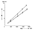
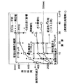
さらに、図3の試験装置を用いて軸受の直径Dm=42mm、針状コロの直径Da=2mmのスラスト針状コロ軸受について、lr/Da=1.9(すなわちlr=3.8mm)で、クラウニング部が形成されていない針状コロを有する第1の軸受と、lr/Da=1.9(すなわちlr=3.8mm)で、0.95mm以上のクラウニング部、すなわち、軌道面との接触長さがコロ全長である3.8mmの3/4以下のクラウニング部が形成されている針状コロを有する第2の軸受と、lr/Da=1.0(すなわちlr=2.0mm)で、クラウニング部が形成されていない第3の軸受について、荷重を変えて動トルクを測定したところ、図4のような結果が得られた。
【0029】
すなわち、図4の実線は上記第1の軸受、破線は上記第2の軸受、一点鎖線は上記第3の軸受の測定結果を示しており、実線で示した上記第1の軸受では、lr/Daが1.9と比較的小さくても、クラウニング部が形成されていない場合には、動トルクが大きくなることを示している。また、一点鎖線で示した上記第3の軸受では、クラウニング部が形成されていなくてもlr/Daが1.0であり、コロ長lrが2.0mmと短いので動トルクが小さくなることを示しているが、この場合はコロが回転する等して姿勢が不安定になる。一方、破線で示した上記第2の軸受では、動トルクは上記第3の軸受に比べるとほんの僅かだけ小さくなるが、姿勢が不安定になることはない。
【0030】
従って、針状コロは、コロ径Daとコロ長lrとの比(lr/Da)が1.2〜2.0となるようにし、クラウニングを形成して相手軌道面との接触長さlaが全長lrの3/4以下となるようにするのが好ましい。なお、第1の発明においては、代替フロンおよび作動油の環境下で使用した場合等において、コロの損傷を防止するため、保持器をコロ持たせではなくレース持たせにすることが望ましい。
【0031】
[第2の発明の実施例]
HFC(ハイドロフルオロカーボン)等の代替フロンとPAG(ポリアリキレングリコール)の環境下において水分によって発生する軸受材料の腐食に対する耐食性を改善すべく、種々検討した結果、軸受鋼の表面に或る程度の窒素を含有させることが有効であることを見出だした。
【0032】
すなわち、SUJ2を内外輪(上下のレース)および転動体の材料として用い、図5(a)に示すように、吸熱形ガスとエンリッチガスとアンモニアガスの雰囲気の下で、840℃で浸炭窒化処理を行った後、図5(b)に示すように、180℃で2時間の焼戻しを行った。この際、表面窒素含有量の調整は、アンモニア濃度を変更することにより行った。なお、軸受材料は、SUJ2の他に、ステンレス鋼に属さない低合金鋼、例えば浸炭鋼を用いてもよい。
【0033】
そして、摩擦低減のための表面処理として、保持器に対して、まず下地処理として、その表面を燐酸塩処理した(膜厚5μm)。そして、さらにその上に二硫化モリブデン(MoS2 )および四フッ化エチレン(PTFE)をポリアミドイミドをバインダーとして焼成膜(膜厚15μm)を形成した。なお、下地処理においては、燐酸塩処理に代えて浸硫化処理、浸硫窒化処理、ガス軟窒化処理を行うことも可能であり、以上の下地処理に先だって浸炭、または浸炭窒化処理を施してもよい。また、二硫化モリブデンおよび四フッ化エチレンは、これらを単独で用いてもよい。また、前記下地処理の後、Ag、Snなどの金属固体潤滑剤層をめっき等により設けることも、耐焼付性向上に有益である。
【0034】
さらに、バインダーとして用いる合成樹脂は、ポリアミドイミドに限らずエポキシ樹脂等の他の熱硬化樹脂を用いることもできる。このような摩擦低減のための固体潤滑剤焼成等による表面処理は、保持器以外の転動体、内輪、外輪の少なくとも1つに施してもよい。また、下地処理である前記燐酸塩処理に代えて浸硫化処理、浸硫窒化処理、ガス軟窒化処理のいずれかを潤滑膜として単独で用いてもよい。さらに、浸炭、または浸炭窒化処理のいずれかを施し、その後、浸硫化処理、浸硫窒化処理、ガス軟窒化処理のいずれかを施したものを潤滑膜としてもよい。なお、これら第2の発明の実施例に係る保持器の表面処理の変形例については、後で詳述する。
【0035】
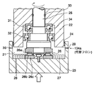
図6は、軸受用の寿命試験機の概略構成を示す図であり、この寿命試験機は、電気製鋼所編「特殊鋼便覧」(第1版、理工学社、1965年5月25日発行)の第10頁−第21頁に記載のスラスト形軸受鋼寿命試験機を基本として、試験室に代替フロンを封入した状態でその試験部を密閉したものである。
【0036】
すなわち、試験室21は、下面に凹部が形成された上側固定部22と上面に凹部が形成された下側固定部23とが、Oリング24により嵌合されることにより密閉空間を形成可能となっている。そして、スピンドル25は、下側固定部23と下側固定部23とに支承され、スピンドル25に取付けられた回転円盤部25aの下面と下側固定部23の上面との間に、試験対象の試験片(軸受)26を配置できるように構成されている。なお、31はスラスト軸受、32はラジアル軸受、33はシール、34は間座である。
【0037】
なお、図6における26aは軸受の上レース、26bは軸受のコロおよび保持器、26cは軸受の下レースである。また、27は潤滑油であり、この潤滑油27は潤滑油供給口(排出口)28から試験室21内に供給される。また、29,30は、それぞれ代替フロン用の導入口、排出口である。代替フロン134aを導入口29より導入、排出口30より真空ポンプで吸引し、試験室21を代替フロン134aで満たした後は、導入口29、排出口30をバルブで閉鎖する。
【0038】
このような試験機を用いて、スラスト針状軸受について、Pmax=2000Mpa、N=4900c.p.m、雰囲気はHFC134a(1気圧)、潤滑油はPAG(VG48;3%水含有)という条件の下で試験を行ったところ、表2〜3に示したような試験結果が得られた。なお、試験片作成にあたり、熱処理後の研削取代は、全て片側0.15mmとした。また、試験部21の振動値が初期値の2倍に達した時点をもって寿命とした。
【0039】
表2〜3に示した試験結果について検討すると、試料番号1〜3は、表面処理が施されておらず、表面粗さも0.1Raと良好ではないが、表面窒素含有量が少なくとも0.09%である。このため、ピーリングが発生し、摩耗度も大きいが、ピットおよび剥離は発生せず、少なくとも10×106回転(rpm)の耐久寿命を達成することができる。試料番号4は、表面処理も施されておらず、表面窒素含有量も0.07%と少なく、表面粗さも0.1Raと良好ではないため、ピーリング、ピットおよび剥離が発生し、摩耗度も大きいため、1×10⁶回転の耐久寿命しか得られない。また、試料番号5は、表面処理が施されておらず、表面粗さも0.1Raと良好ではないが、表面窒素含有量が0.6%と多いため、ピーリングが発生し、摩耗度も大きいが、ピットおよび剥離は発生せず、13×106回転の耐久寿命を達成することができる。しかし、このように表面窒素含有率が0.6%と多くなると、研削性が劣化し、製造コストが上昇することとなる。
【0040】
【表2】
【表3】
【0042】
試料番号8〜10は、表面粗さが少なくとも0.08Ra以上であり良好ではないが、表面窒素含有量が少なくとも0.09%以上あり、表面処理も施されているため、ピーリングは発生するものの、ピットおよび剥離は発生せず、摩耗度も小さいため、少なくとも22×106回転の耐久寿命を達成することができる。
【0043】
試料番号11は、表面処理が施されておらず、表面粗さも0.1Raと良好ではないが、表面窒素含有量が少なくとも0.3%である。このため、ピーリングが発生し、摩耗度も大きいが、ピットおよび剥離は発生せず、10×106回転の耐久寿命を達成することができる。試料番号12は、表面窒素含有量が0.05%と少なく、表面粗さも0.1Raと良好ではないが、表面処理が施されている。このため、ピット、剥離、およびピーリングが発生するが、摩耗度が小さいため、最低限5×10⁶回転の耐久寿命は達成することができる。
【0044】
試料番号13〜18は、表面処理が施されていないが、表面窒素含有量が少なくとも0.1%以上あり、表面粗さが少なくとも0.05Ra以下であり良好であるため、摩耗度は大きいが、ピット、剥離、およびピーリングが発生せず、少なくとも20×106回転の耐久寿命を達成することができる。試料番号19は、表面処理が施されておらず、表面粗さも0.08Raと良好ではないが、表面窒素含有量が0.3%であるため、ピーリングが発生し摩耗度も大きいが、ピットと剥離は発生せず、10×106回転の耐久寿命を達成することができる。試料番号20は、表面窒素含有量が0.07%と少なく、表面処理も施されていないが、表面粗さが0.01Raと良好であるため、ピットと剥離が発生し摩耗度も大きいが、油膜の形成が促進されてピーリングは発生せず、最低限5×10⁶回転の耐久寿命は達成することができる。
【0045】
試料番号21〜24は、表面窒素含有量が0.03%と少ないが、表面処理が施されており、表面粗さも少なくとも0.05Ra以下であり良好であるため、ピットと剥離が発生するが、ピーリングは発生せず摩耗度も小さいため、10×106回転の耐久寿命を達成することができる。試料番号25は、表面窒素含有量が0.03%と少なく、表面粗さも0.07Raと良好ではないが、表面処理が施されているため、ピット、剥離、ピーリングは発生するが、摩耗度が小さいため、最低限5×10⁶回転の耐久寿命は達成することができる。試料番号26は、表面窒素含有量が0.03%と少なく、表面処理も施されていないが、表面粗さが0.05Raと良好であるため、ピットと剥離が発生し摩耗度も大きいが、油膜の形成が促進されてピーリングが発生しないため、最低限5×10⁶回転の耐久寿命は達成することができる。
【0046】
試料番号27〜35は、表面窒素含有量が少なくとも0.09%以上あり、表面処理も施されており、表面粗さも少なくとも0.05Ra以下であり良好であるため、ピット、剥離、ピーリングのいずれも発生せず摩耗度も小さいため、少なくとも50×106回転の耐久寿命を達成することができる。試料番号36は、表面粗さが0.07Raであり良好ではないが、表面窒素含有量が0.3%もあり、表面処理も施されているため、ピーリングは発生するもののピットと剥離は発生せず摩耗度も小さいため、少なくとも20×106回転の耐久寿命を達成することができる。試料番号37は、表面処理は施されていないが、表面窒素含有量が0.3%もあり、表面粗さも0.03Raであり良好なので、摩耗度は大きいが、ピット、剥離、ピーリングのいずれも発生せず、20×106回転の耐久寿命を達成することができる。試料番号38は、表面窒素含有量が0.07%と少ないが、表面処理が施されており、表面粗さも0.03Raであり良好なので、ピットと剥離は発生するがピーリングは発生せず、摩耗度も小さいので、10×106回転の耐久寿命を達成することができる。
【0047】
このように、表面窒素濃度を適切に調節してピットおよび剥離の発生を防止し、または表面粗さを適切に調節して油膜の形成を促進してピーリングの発生を防止し、または表面処理を施して摩擦を低減することによって、ピットが発生してたとえ油膜切れが生じても表面被膜等の存在により金属接触を防止することにより、代替フロン、および水混入潤滑油の環境下でも転がり軸受の長寿命化を図ることができる。この場合、上記試験結果から、表面窒素濃度は0.08%〜0.5%とすることが望ましく、表面粗さは0.05Ra以下とすることが望ましい。なお、表面窒素濃度の上限を0.5%としたのは、これ以上の濃度にしても特段に寿命が延びることがないばかりでなく、研削性の劣化に伴って製造コストが上昇するからである。
【0048】
なお、摩擦低減のための固体潤滑剤焼成等による表面処理は、上記試験においては保持器に対してのみ施したが、保持器以外の転動体、内輪、外輪の少なくとも1つに施してもほぼ同等の効果が得られた。
【0049】
次に、前記表面処理の変形例について、保持器を例に詳述する。なお、ここでは、保持器の素材としては、冷間圧延鋼板(SPCC)を用い、その形状は、図21に示すものと同一のものを用いているが、これに限らず、各種の鋼、その他の金属(好ましくは耐食性を有するもの)を素材とし、圧延でなく切削加工により作られるものでもよい。
【0050】
表面処理は、大別して、
(A)前記のスラスト針状ころ軸受の試験で用いたような、下地処理を施し、その上に固体潤滑剤を被覆するものと、
(B)素地の鉄と窒素と炭素との化合物、または鉄と窒素と炭素と硫黄との化合物(ただし、両方とも炭素は除いてもよい)を素地表面に形成するものとがある。
【0051】
前者(A)に関しては、ここでは固体潤滑剤としては四フッ化エチレン(PTFE)をポリアミドイミドをバインダとしてコーティングしたものについて取上げるが、前述したように、これに代え、固体潤滑剤としては二硫化モリブデン(MoS2 )や二硫化タングステン(WS2 )等、他のものを用いてもよく、或いは、これらの2種類を混合したものでもよい。また、バインダとしては、ポリアミドイミド、エポキシ樹脂等を適宜選択してもよく、これらいずれの固体潤滑剤、およびバインダのであっても、以下に示す試験結果と同等の作用・効果が得られる。
【0052】
前記固体潤滑剤の下地処理としては、▲1▼浸炭、または浸炭窒化処理、▲2▼浸硫化、または浸硫窒化処理、▲3▼ガス軟窒化処理、▲4▼燐酸塩処理(例えば燐酸マンガン塩被膜処理、燐酸亜鉛被膜処理等)を単独で施すか、或いは▲5▼前記▲1▼の処理を1次処理とし、この1次処理と、2次処理としての▲2▼、▲3▼、または▲4▼の少なくともいずれかとを組合わせたものを施すことができる。さらに、▲1▼、▲2▼、▲3▼、または▲5▼の下地処理の後、▲4▼の処理を施してもよい。
【0053】
▲4▼の処理により形成される燐酸塩処理被膜は、表面に凹凸を生じ、その上に塗膜される固体潤滑剤およびバインダとの接触表面積が増すことにより、バインダと強く結合することとなり、固体潤滑剤と素地表面との密着性を高める働きがある。この働きは、1例として燐酸マンガン塩被膜で確認したところ、膜厚は4μm〜10μmが好ましいことが判明した。すなわち、4μm未満の膜厚では、表面の凹凸が十分ではなく、密着性が不十分となり、膜厚が10μmを越えると、表面が粗くなりすぎ、上に固体潤滑剤を塗膜した状態でも粗さが残り、保持器して使用した場合に油膜が切れる部分が生じる等、潤滑条件が悪化し、また、寸法公差も悪くなるという不具合を生じる。従って、本実施例では、燐酸塩処理被膜の膜厚は4μm〜10μmとした。なお、前記固体潤滑剤の下地処理の他の例としては、後述するように、ここでは、代表例として浸炭窒化処理を取上げた。
【0054】
後者(B)に関しては、鉄と窒素との化合物層を形成させる処理として、ガス軟窒化処理があり、鉄と窒素と硫黄との化合物層を形成させる処理として、浸硫窒化処理があり、更にこれらの化合物の成分として炭素を加える処理としては、1次処理としての浸炭、または浸炭窒化処理と、その後に行う1次処理としてのガス軟窒化処理(または浸硫窒化処理)とを組合わせた処理などがあり、いずれも保持器の摩耗低減に効果がある。また、窒素や炭素は母材(素地)金属との化合物を形成し、保持器の強度(変形力に対する強度、および疲労強度)を向上させる効果もある。
【0055】
以下、上記の効果を試験例に基づいて詳細に説明する。この試験では、試料の軸受としては、FP501724およびFP501729(いずれもスラストニードル軸受、外径37mm、内径17mm、組立てた状態での幅が7mm、その保持器(試験対象:試料)は、図21に示したものと同一形状のプレス成形したSPCC鋼板製で、外径34mm、内径17mm、高さ最大2.15mm)のものを用い、転動体(ニードル)および軌道輪は、いずれもSUJ2からなり、表面窒素含有率0.3重量%、表面粗さ0.03Raのものを使用した。
【0056】
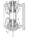
図7は、この試験に用いた寿命試験機の概略構成を示す図であり、この寿命試験機は、1対の軸受41a、41bにより回転自在に支持されたシャフト42に2つの試験軸受43a、43bを取付け、ガイド44で支持されたハウジング45を介してスラスト荷重Faを試験軸受43a、43bに負荷し、図示省略したモータおよびベルトによりプーリー46を回転駆動するように構成されている。
【0057】
また、シャフト42には、試験軸受43a、43bをそれぞれ取付けるためのレース固定部47aおよびレース回転部48a、レース固定部47bおよびレース回転部48bが設けられており、レース回転部48a,48bはシャフト42と一体になって回転し、レース固定部47a,47bは回転禁止されるように構成されている。試験軸受43aの第1軌道輪49、第2軌道輪50は、それぞれレース固定部47a、レース回転部48aに係止され、試験軸受43bの第1軌道輪49、第2軌道輪50は、それぞれレース固定部47b、レース回転部48bに係止される。そして、シャフト42が回転すると、試験軸受43a、43bの第2軌道輪50は、転動可能に保持器51に保持されたニードル52の作用により、レース回転部48a、48bと一体になって回転駆動されるが、試験軸受43a、43bの第1軌道輪49は、それぞれレース固定47a、47bによって回転停止状態が維持される。
【0058】
試験条件は、回転速度は5000rpm、スラスト荷重は500kgf、潤滑条件は5gのPAGオイル(3%の水分を含む)とした。なお、PAGオイルは、試験機に試験軸受43a、43bを組込む前に、固定側の軌道輪を外した状態で保持器のポケット部に注射器により滴下して供給した。
【0059】
試験対象の保持器(SPCC鋼板製)に対する浸炭窒化処理は、吸熱形ガス+エンリッチガス+アンモニアガスの雰囲気で0.5時間行った後、200℃で2時間の焼戻しを行った。なお、浸炭窒化処理に代えて例えば浸炭処理を行ってもよい。ガス軟窒化処理は、500℃から600℃の条件下でアンモニアガスを用いて1時間の窒化処理を施したものを、200℃で2時間の焼戻しを行った。
【0060】
浸硫窒化処理は、還元性塩浴法によりシアン酸塩を使い、硫酸ナトリウム、亜硫酸ナトリウムの硫黄化合物を添加した塩浴中で560℃で1時間の処理を行った。また、四フッ化エチレンのコーティングは、ポリアミドイミドをバインダーとした有機溶剤をスプレーにて塗膜し、200℃で1時間の熱処理により形成したものである。特に、本実施例では、四フッ化エチレンと素地表面との密着性を高めるめる目的で、保持器表面に燐酸マンガン塩被膜処理を施した。
【0061】
ガス軟窒化処理により得られる組織は、窒化物(主としてFe3 N)の表面層と窒素の内部拡散層で形成される。表面窒素濃度は処理温度に依存し、500℃以下でも窒素を固溶する窒化物層が形成されるが、耐摩耗性の点では、特に500℃(さらに好ましくは545℃)から600℃でのガス軟窒化処理が好ましい。また、Fe3 Nとなる窒化物の表面層と窒素の内部拡散層の硬化層深さは処理時間に依存し、耐摩耗性の向上に寄与する。さらに、浸炭、もしくは浸炭窒化処理の1次処理と、ガス軟窒化処理の2次処理とを組合わせることにより、炭素をほとんど固溶しないFe4 Nの組織である拡散層に炭素を固溶させることが可能となり、硬度が高くなり耐焼付性が向上する。
【0062】
また、浸硫窒化処理の硬化層深さは処理時間に依存する。数μmの化合物層で耐摩耗性は向上するが、処理温度を500℃から600℃とするのが望ましい。また、浸炭、もしくは浸炭窒化処理の1次処理と、浸硫窒化処理の2次処理とを組合わせることにより、炭素を表面に固溶させた鉄と硫黄と窒素と炭素との化合物を形成させることが、耐摩耗性と耐焼付性の点で望ましい。
【0063】
上記の各種表面処理を膜厚または硬化層深さを変えて施した保持器を有する軸受について、図7に示した寿命試験装置を用いて試験した試験結果を図8,図9に示す。図8は、浸炭窒化処理を予め施した後に、ガス軟窒化処理、浸硫窒化処理、四フッ化エチレン(PTFE:下地処理により、膜厚4μm〜5μmの燐酸マンガン処理被膜が形成されたもの)被膜処理をそれぞれ行った場合の膜厚と保持器の焼付時間との関係を示し、図9は、浸炭窒化処理を施さずに、図8と同様のガス軟窒化処理、浸硫窒化処理、PTFE被膜処理をそれぞれ行った場合の膜厚と保持器の焼付時間との関係を示している。
【0064】
図8,図9の試験結果を検討すると、浸炭窒化処理を予め施すか否かに拘らず、ガス軟窒化処理、浸硫窒化処理、PTFE被膜処理のいずれかを施すと、保持器の焼付時間は、図8,図9に破線で示した未処理の場合の焼付時間よりも長くなり、寿命の向上が認められる。
【0065】
また、浸炭窒化処理を予め施すか否かに拘らず、ガス軟窒化処理、または浸硫窒化処理を施すと、いずれも硬化層深さ(ここでは硬さHvが320〜350以上となる深さ、さらに望ましくは硬さHvが450〜500以上となる深さで定義する。)が10μmになったときに未処理の場合より耐摩耗性が向上し、焼付時間が長くなり、硬化層深さは10μm以上が好ましいことが判明した。また、硬化層深さを20μm以上にしても、処理時間がかかる割りには焼付時間はそれほど延びず、寿命向上の効果が上がらないことも判明した。従って、経済性を考慮すると、ガス軟窒化処理、または浸硫窒化処理、あるいは浸炭窒化処理とこれらの処理との組合せによる硬化層深さは、10μm〜20μmとするのが好ましいことが確認された。
【0066】
上記PTFE被膜処理については、浸炭窒化処理を予め施すか否かに拘らず、ガス軟窒化処理、または浸硫窒化処理を施した場合より大幅に焼付時間が長くなり、2μm程度の膜厚で、ガス軟窒化処理、または浸硫窒化処理の焼付時間の飽和値に匹敵する効果が得られるが判明した。また、PTFE被膜処理の場合、浸炭窒化処理を予め施したときは膜厚が10μm以上、浸炭窒化処理を施さないときは膜厚が20μm以上になると、寿命向上の効果が飽和することが判明した。なお、膜厚が30μmを越えると、寸法公差に影響を及ぼし、転動体との間の隙間が大きくなり過ぎる部分や、小さくなり過ぎる部分が生じるという不具合が発生することが確認されているので、これらを考慮すると、PTFE被膜の膜厚は、2μm〜30μm(好ましくは10μm〜30μm)が望ましいことが確認された。
【0067】
図8の浸炭窒化処理を予め施した場合と図9の浸炭窒化処理を施さない場合とを比較すると、浸炭窒化処理を予め施した場合の方が、ガス軟窒化処理、浸硫窒化処理、PTFE被膜処理のいずれについても、より寿命が向上していることが分かる。この浸炭窒化処理による寿命の向上について、ガス軟窒化処理を例にして、図10に基づいて説明する。
【0068】
図10は、SPCC鋼板(厚さ0.5mm)に浸炭窒化処理、またはガス軟窒化処理、または浸炭窒化処理を予め施した後にガス軟窒化処理を施した場合の、表面からの深さと硬さ(Hv)との関係を測定した結果を示している。
【0069】
図10に示したように、浸炭窒化処理のみでは表面層の硬さは800Hv以上であるが、内部深さ80μmでは200Hv以下(SPCCの母材硬さ)の硬さになり、表面から伝えられる応力に対して十分支えきれない。また、ガス軟窒化処理のみでは、内部硬さは母材硬さより上昇するが、表面硬さが400Hv以下となり他の2つの場合よりは耐摩耗性が劣ることとなる。
【0070】
一方、浸炭窒化処理とガス軟窒化処理を組合わせた場合は、表面硬さ580Hv、内部硬さ300Hv以上の耐摩耗性の優れた表面が得られる。つまり浸炭窒化により表面層が硬化されるが、後のガス軟窒化処理により表面から芯部に向かって窒素は深く拡散できるが焼戻りによる硬さ低下が生ずる。つまり、表面層窒化の侵入拡散による硬さの上昇と焼戻りによる硬さ低下の両現像が複合されて表面層の硬度は浸炭窒化処理のみよりも低く、ガス軟窒化処理のみより高くなり、芯部はガス軟窒化処理と同等になることを示している。さらに、保持器の疲労度も強くなるため、ころを抱える柱(間仕切り部)の破損も防止できる。さらに、内部まで硬くなることにより、保持器の変形も生じにくくなる。また、図10に示したように、浸炭窒化処理を施した後にガス軟窒化処理を施した場合は、浸炭窒化処理だけを施した場合に比べて、結果のバラツキが小さくなっている。これは、表面層に仮に摩耗または損傷が生じても、下地である浸炭窒化層が支えることにより、信頼性が増すためと考えられる。
【0071】
以上説明したように、代替フロン等の水混入潤滑環境下においても、スラストニードル軸受の保持器として、少なくとも窒素を含有させるための所定の処理を施したものを使用することにより、あるいは所定の下地処理により素地との密着性を確保した上で固体潤滑剤を被膜することにより、耐摩耗性および潤滑条件を向上させて焼付の発生を遅延させることにより、保持器の長寿命化を達成できるようになる。なお、上記の各種表面処理を施したのであれば、スラストニードル軸受に限らず、他のタイプの各種軸受に適用できることは言うまでもない。また、保持器以外の転動体、軌道輪に適用することも可能である。
【0072】
[第3の発明の実施例]
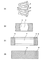
図11〜図20は、それぞれ第3の発明の実施例によるスラスト針状コロ軸受の保持器の構成図であり、図11(a)は保持器の平面図、図11(b)は図11(a)のA−A´断面図、図11(c)は図11(a)のB−B´断面図、図11(d)は図11(a)のC−C´断面図である。なお、図12〜図20においても同様に、(a)を付した図は保持器の平面図であり、(b)を付した図は(a)を付した図のA−A´断面図、(c)を付した図は(a)を付した図のB−B´断面図、(d)を付した図は(a)を付した図のC−C´断面図である。
【0073】
図11〜図19に示した転がり針状コロ軸受の保持器は、金属製コア、または金属製リングと樹脂部とにより構成されている。ここで、金属の種類については特に限定されないが、冷間圧延鋼板(SPCC)等を使用できる。
【0074】
一方、樹脂材料は、摺動性、耐熱性、耐薬品性、耐油性、強度に優れた材料が好ましく、具体的には、ナイロン66樹脂、ナイロン46樹脂、ポリフェニレンサルファイド樹脂(PPS樹脂)、或いはこれら樹脂にガラス繊維、炭素繊維等の短繊維を混入して強化した材料が好ましい。ナイロン66樹脂は、デュポン(株)の「ザイテル」、宇部興産(株)の「UBEナイロン」、ピーエーエスエフエンジニアリング プラスチック(株)の「ウルトラミッドA」として、ナイロン46樹脂は、帝人(株)の「テイジン46ナイロン」、日本合成ゴム(株)の「Stanyl」として、PPS樹脂は、呉羽化学工業(株)の「フォートロンKPS」として入手できる。
【0075】
図11〜図19に示した保持器の製造方法としては、予め製造された金属製コア、または金属製リングを金型内に装着したとき、転動体案内部の一部または全部に相当する部分に空間が形成されるような金型を用意し、その空間に樹脂を射出成形により形成する方法や、金属製コア、または金属製リングと樹脂部を別々に製造し、樹脂のスナップフィット性等を利用して組み立てる方法がある。
【0076】
図11の保持器は、基本的には樹脂部Rにより構成されているが、各ポケット部Pとポケット部Pとの間(間仕切り部:柱部)の上面部であってポケット部の近傍を除く部分、各ポケット部Pの端面と内周面、および外周面との間は、金属部Mにより構成されている。すなわち、コロの側面と接触するポケット部Pの側面は樹脂部Rが露出した状態となっており、コロの端面と接触するポケット部Pの端面は、金属部Mが露出した状態となっている。なお、各ポケット部Pとポケット部Pとの間では、図11(d)に示したように、金属部Mの内周側の内面、および外周側の内面に、樹脂部Rの脱落を防止するための突起部Maが形成されている。
【0077】
図12の保持器は、基本的には樹脂部Rにより構成されているが、各ポケット部Pよりも外側の外周部分は金属部Mにより構成されている。すなわち、コロと接触するポケット部Pの全ての面は、樹脂部Rが露出した状態となっている。なお、図12(d)に示したように、金属部Mの内面の上部と下部には、樹脂部Rの脱落を防止するための突起部Maが全周に亘って形成されている。
【0078】
図13の保持器は、基本的には樹脂部Rにより構成されているが、外周部分は金属部Mにより構成されている。すなわち、コロと接触するポケット部Pの全ての面は、樹脂部Rが露出した状態となっている。なお、金属部Mは、図13(a)、(d)に示したように、各ポケット部Pとポケット部Pとの間では、上面部分が内周側に突出した状態となっている。
【0079】
図14の保持器は、基本的には樹脂部Rにより構成されているが、各間仕切り部の上面部であってポケット部の近傍を除く部分、各ポケット部Pの端面から内周側の上面にかけて、各ポケット部Pの端面から外周側の上面にかけての部分は、金属部Mにより構成されている。すなわち、コロの側面と接触するポケット部Pの側面は樹脂部Rが露出した状態となっており、コロの端面と接触するポケット部Pの端面は、金属部Mが露出した状態となっている。
【0080】
図15の保持器は、基本的には樹脂部Rにより構成されているが、外周部分は金属部Mにより構成されている。すなわち、コロと接触するポケット部Pの全ての面は、樹脂部Rが露出した状態となっている。なお、図15(a)、(d)に示したように、金属部Mは、各ポケット部Pとポケット部Pとの間では、上面部分が内周側に突出した状態となっており、この突出部分には、孔Hが形成されていて、この孔Hに樹脂が充填されることにより、金属部Mと樹脂部Rとが強固に結合するようになっている。
【0081】
図16の保持器は、基本的には樹脂部Rにより構成されているが、各間仕切り部の中層部であってポケット部の近傍を除く中層部分と、この中層部分と内周面との間の中層部および下層部、中層部分と外周面との間の中層部および上層部は、金属部Mにより構成されている。すなわち、コロの側面と接触するポケット部Pの側面は樹脂部Rが露出した状態となっており、コロの端面と接触するポケット部Pの端面の一部は、金属部Mが露出した状態となっている。
【0082】
図17の保持器は、基本的には樹脂部Rにより構成されているが、各ポケット部Pから外側の外周部分は金属部Mにより構成されている。すなわち、コロの側面と接触するポケット部Pの側面は樹脂部Rが露出した状態となっており、コロの端面と接触するポケット部Pの外側の端面は、金属部Mが露出した状態となっている。なお、金属部Mは、ポケット部Pの外側の端面と対向する部分では肉厚が厚くなっており、ポケット部と金属部Mとの位相がずれないように工夫されている。
【0083】
図18の保持器は、基本的には樹脂部Rにより構成されているが、各ポケット部Pから外側の外周部分は金属部Mにより構成されている。すなわち、コロの側面と接触するポケット部Pの側面は樹脂部Rが露出した状態となっており、コロの端面と接触するポケット部Pの外側の端面は、金属部Mが露出した状態となっている。なお、金属部Mには、その中層部分に凹部が形成され、樹脂部Rが金属部Mから脱落しないように工夫されている。
【0084】
図19の保持器は、基本的には樹脂部Rにより構成されているが、各ポケット部Pよりも外側の外周部分は金属部Mにより構成されている。すなわち、コロと接触するポケット部Pの全ての面は、樹脂部Rが露出した状態となっている。なお、金属部Mには、ポケット部Pの外側の端面との対応部の中層部分には凹部が形成され、樹脂部Rが金属部Mから脱落しないように工夫されている。
【0085】
図20の保持器は、その全てが樹脂部Rにより構成されている。この図20の樹脂製の保持器は、射出成型により製造することができる。なお、図21は従来の冷間圧延鋼板(SPCC)製の保持器を示しており、図21(a)は平面図、図21(b)は図21(a)のC−C´断面図である。
【0086】
図11〜図14、および図20の構造の保持器を、樹脂部Rの樹脂の種類を替えて作成し、日本精工(株)製のスラストニードル型寿命試験機により寿命試験を行ったところ、表4のような試験結果が得られた。なお、試験条件は、Pmax=2000MPa、N=4900c.p.m、雰囲気は代替フロンとしてのHFC(ハイドロフルオロカーボン)134a(2気圧)、潤滑油はPAG(ポリアリキレングリコール)とした。また、試験軸受の寸法は外径37mm、内径17mm、幅14mmとし、コロ径は2.5mm、コロ長さは5.6mmとした。また、耐久寿命の評価は、10×106回転未満は耐久性なし(×)、10×106回転以上〜50×106回転未満は耐久性有り(○)、50×106回転以上は耐久性大いに有り(◎)とした。
【0087】
【表4】
【0088】
試験例4のように、図12の保持器の樹脂部Rの樹脂として、ナイロン66樹脂とガラス繊維との重量%比が70:30の樹脂を用いた場合、軸受の耐久寿命は10×106回転以上〜50×106回転未満となり、耐久性は良好となる。試験例5のように、図12の保持器の樹脂部Rの樹脂として、ナイロン46樹脂とガラス繊維との重量%比が70:30の樹脂を用いた場合、軸受の耐久寿命は50×106回転以上となり、耐久性は非常に良好となる。また、試験例6のように、図12の保持器の樹脂部Rの樹脂として、PPS(ポリフェニレンサルファイド)樹脂とガラス繊維との重量%比が70:30の樹脂を用いた場合、軸受の耐久寿命は10×106回転以上〜50×106回転未満となり、耐久性は良好となる。
【0089】
試験例7のように、図13の保持器の樹脂部Rの樹脂として、PPS樹脂とガラス繊維との重量%比が80:20の樹脂を用いた場合、軸受の耐久寿命は10×106回転以上〜50×106回転未満となり、耐久性は良好となる。試験例8のように、図14の保持器の樹脂部Rの樹脂として、PPS樹脂とガラス繊維との重量%比が80:20の樹脂を用いた場合、軸受の耐久寿命は50×106回転以上となり、耐久性は非常に良好となる。
【0090】
図20の樹脂製の保持器の樹脂として、試験例9のように、PPS樹脂とガラス繊維との重量%比が80:20の樹脂を用いた場合、試験例10のように、ナイロン46樹脂とガラス繊維との重量%比が70:30の樹脂を用いた場合、試験例11のように、ナイロン66樹脂とガラス繊維との重量%比が80:20の樹脂を用いた場合、いずれも軸受の耐久寿命は10×106回転以上〜50×106回転未満となり、耐久性は良好となる。これに対して、試験例12のように、図21の金属製の保持器を用いた場合には、軸受の耐久寿命は10×106回転未満となり、耐久性がなくなってしまう。
【0091】
次に、軸受の耐久寿命について考察する。保持器と転動体の摺動性をみると、上記試験における代替フロンの雰囲気のような潤滑性に劣る条件下では、金属製の保持器の場合、保持器と転動体の間に十分な潤滑油膜は形成されず、金属−金属接触が起こり、急激に摩耗が進行する。金属−金属接触が起こる理由の1つとしては、金属は樹脂に比べて剛性が高く、保持器と転動体間の接触部に高い応力が発生することが考えられる。
【0092】
これに対して、保持器の転動体用の案内部に樹脂材料を使用すると、樹脂は金属に比べて弾性率が極端に大きく、高い応力を受けても樹脂自体が変形して応力が分散されることとなる。また、無潤滑下での摩擦摩耗度は、金属−金属摩擦よりも金属−樹脂摩擦の方が低くなる性質がある。
【0093】
一方、保持器の剛性に関しては、金属製保持器の方が樹脂製保持器よりも優れている。従って、図11〜図19の保持器では、金属部Mにより剛性が保たれるので、高速で回転する転動体の遠心力によってクリープ変形が起こるのを防止でき、また、転動体の案内部には樹脂部Rが形成されているので、保持器と転動体の異常摩耗や焼き付けを防止できる。これにより、たとえ代替フロンの雰囲気のような潤滑性に劣る条件下で使用しても、軸受の長寿命を達成することができる。
【0094】
なお、代替フロン等の環境下で使用する場合であっても、低速回転、低荷重用の軸受として利用する場合には、剛性がそれほど大きくなくてもクリープ変形が起こることはないので、簡単に製造できる図20の樹脂製の保持器を使用し、保持器と転動体の異常摩耗や焼き付けを防止するだけで、軸受の長寿命を達成することができる。
【0095】
[第2の発明の実施例の変形例]
図8、図9において、浸炭窒化処理の有無に拘らず四フッ化エチレン(PTFE)被膜が最も耐焼付性向上に効果のあることを確認したが、ここでは、さらに、被膜形成方法について改良を加えた前記第2の発明の実施例の変形例について説明する。すなわち、前記第2の発明の実施例では、固体潤滑剤としての四フッ化エチレン(PTFE)等は、エアーを用いたスプレーによってコーティングしたが、本変形例では、スプレーに拠らず塗布することによりコーティングする点で異なる。以下、本変形例を詳細に説明する。
【0096】
保持器の素材としては、冷間圧延鋼板(SPCC)を用い、その形状は、図21に示したものと同一のものを用いるが、これに限らず、各種の鋼、その他の金属(好ましくは耐食性を有するもの)を素材として、圧延ではなく切削加工により作られたものでもよい。
【0097】
ここでは、固体潤滑剤としては、最も耐焼付性の効果の高い四フッ化エチレン(PTFE)をポリアミドイミドをバインダーとしてコーティングしたものについて取り上げるが、前述のように、これに代えて固体潤滑剤としては、二硫化モリブデン(MoS2)や二硫化タングステン(WS2)等、他のを用いてもよく、四フッ化エチレン(PTFE)と上記のうちの1つとを混合したものでもよい。また、バインダーとしては、ポリアミドイミド、エポキシ樹脂等を適宜選択してもよく、これらいずれの固体潤滑剤、バインダーであっても、以下に示す試験結果と同等の作用・効果が得られる。
【0098】
固体潤滑剤の下地となる燐酸塩処理膜は、表面に凹凸を生じ、その上に塗膜される固体潤滑剤およびバインダーとの接触面積が増すことにより、バインダーと強く結合することになり、固体潤滑剤と素地表面との密着性を高める働きがある。この働きは、1例として燐酸マンガン塩被膜で確認したところ、本変形例の場合では、1〜10μmの厚さに成膜するのが好ましいことが判明した(図22参照)。なお、この確認試験においては、1μm未満の膜厚の燐酸マンガン塩被膜は、処理温度と処理時間を調節することにより形成した。例えば、0.9μmの膜厚の燐酸マンガン塩被膜は、燐酸マンガン水溶液による処理温度を60〜70℃に設定して10分間処理することにより形成した。また、10μmを越える膜厚の燐酸マンガン塩被膜は、処理液中の燐酸マンガン成分の濃度を調整することにより形成した。例えば、10μmの厚さに成膜する場合は、燐酸マンガン成分の濃度を4μmの場合の1.2倍にし、40μmのの厚さに成膜する場合は、燐酸マンガン成分の濃度を4μmの場合の1.4倍にした。
【0099】
図22は、保持器に対して下地処理として、上記の方法により燐酸マンガン塩被膜を各種の膜厚で形成し、後述する本変形例に係る塗布方式により四フッ化エチレン(PTFE)を2μmの厚さに成膜した場合の焼付時間を示したものである。図22に示したように、燐酸マンガン塩被膜の膜厚が、1〜10μmの場合に良好な耐焼付性が実現でき、この範囲から遠ざかる程、耐焼付性が急激に劣化している。すなわち、上述のスプレー方式と比較すると、スプレー方式では下限値として4μm必要であったが、本変形例の塗布方式では最低1μmで済む。
【0100】
このように耐焼付性が急激に劣化するのは、1.0μm未満の膜厚では、表面の凹凸が十分ではなく、密着性が不十分となり、膜厚が10μmを越えると、表面が粗くなりすぎ、上に固体潤滑剤を塗膜した状態でも粗さが残り、保持器として使用した場合に油膜が切れる部分が生じる等、潤滑条件が悪化するからである。また、膜厚が10μmを越えた場合には、寸法公差も悪くなるという不具合を生じる。従って、本変形例では、燐酸塩処理膜の膜厚は1〜10μmとした。なお、前記固体潤滑剤の下地としては、燐酸亜鉛、燐酸鉄、燐酸カルシウム等を用いても、以下に示す試験結果と同等の作用・効果が得られる。
【0101】
以下、試験例に基づいて本変形例を詳細に説明する。この試験では、試料の軸受としては、スラストニードル軸受(外径37mm、内径17mm、組立てた状態での幅が7mm)を用い、その保持器(試験対象:試料)としては、図21に示したものと同一形状のプレス成形したSPCC鋼板製で、転動体(ニードル)および軌道輪は、いずれもSUJ2からなるものを使用した。
【0102】
また、寿命試験機としては、第2の発明の実施例の場合と同様に、図7に示したものを使用した。この場合の試験条件も、第2の発明の実施例の場合と同様に、回転速度5000rpm、スラスト荷重500kgf、潤滑条件は1gのPAGオイルとした。このPAGオイルは、試験機に試験軸受43a,43bを組み込む前に、固定側の軌道輪を外した状態で保持器のポケット部に注射器により滴下して供給した。
【0103】
保持器に対する上記下地処理しては、燐酸マンガン塩処理を施した。すなわち、保持器をPH10のアルカリ洗浄液で脱脂した後、亜硝酸ナトリウム溶液で表面調整を行った。なお、燐酸マンガン塩の結晶を均一に形成させるべく、亜硝酸ナトリウムの濃度は、3g/水1lとした。このようにして表面調整を行った後、マンガン濃度11000ppm、鉄濃度2000ppmの燐酸と、PH3.0に調整した硝酸との水溶液中で、95℃で10分間浸せき処理を行うことにより、表面に約8g/m2 の燐酸マンガン塩結晶を形成した。なお、このような下地処理を省いてもテフロン(四フッ化エチレン)コーティングは可能であるが、耐焼き付き性の面では、下地処理を施すことが望ましい。
【0104】
四フッ化エチレンのコーティングは、ポリアミドイミドをバインダーとした有機溶剤のサスペンション液(懸濁液)を塗布して行う。すなわち、保持器7000個を容積0.7m3 の金属製容器の中に入れ、この容器を15rpmで回転させて、保持器同士を互いに接触させる。その中に上記サスペンション液を流し込み、その後、乾燥させて有機溶剤分を蒸発させることにより、四フッ化エチレンとバインダーを保持器の表面に均一塗布(塗膜)する。その後、200℃で1時間熱処理を行い、バインダーを硬化させる。
【0105】
このようにすると、上記実施例のようにエアーでスプレーコーティングする場合と比べて、▲1▼使用するサスペンション液がより少量で済むと共に、▲2▼単位時間当たりの塗膜処理量が約2〜5倍になるため、処理コストを低減できるようになる。また、▲3▼保持器同士が接するので、スプレーコーティングに比べて被膜中の応力が増加するため、薄膜でかつ密度が大きくなり、さらに、密着性が向上し、薄膜であるにも拘らずスプレーコーティングと同等の摺動性を維持できる。なお、本変形例の上記コーティングにおいて、保持器と共に10mm以下のメディア等を混入させてサスペンション液を保持器の表面に塗膜すれば、さらに被膜密度を大きくし、密着性も向上できることが確認されている。
【0106】
上記の表面処理を施した保持器を有する軸受について、図7に示した寿命試験機により上記条件下で行った試験結果を図23に示す。図23は、浸炭窒化処理を施さないものと、浸炭窒化処理を施した後にスプレーにより四フッ化エチレンをコーティングしたもの(上記実施例)と、浸炭窒化処理を施した後に塗布により四フッ化エチレンをコーティングしたもの(本変形例)とについて、耐焼き付き時間と、処理コストとの比較結果を示している。
【0107】
図23から明らかなように、浸炭窒化処理を施さない保持器は、焼き付きに対する耐久時間は、最も短くなっている。これに対して、上記実施例と本変形例に係る保持器では、焼き付きに対する耐久時間は共に大幅に長くなっており、上記実施例に係る保持器よりも本変形例に係る保持器での方が、焼き付きに対する耐久時間はより長くなっている。このように、本変形例の方が上記実施例よりも耐焼き付性能が優れているのは、被膜密度が高く強度が大きいためであると考えらる。また、製造コストは、本変形例の保持器は上記実施例の保持器の約1/2となっている。
【0108】
次に、上記の本変形例の塗布による四フッ化エチレンの表面処理(下地処理として膜厚4μm〜5μmの燐酸マンガン塩処理を施したもの)を膜厚を変えて施した保持器を有する軸受について、図7に示した寿命試験装置を用いて試験した試験結果を図24(前記表面処理に先立ち、浸炭窒化処理を施した場合),図25(浸炭窒化処理を施さない場合)に示す。なお、比較のため、図24には、図8に示した浸炭窒化処理を予め施した後に、ガス軟窒化処理、浸硫窒化処理、およびスプレー方式による四フッ化エチレン(PTFE:下地処理により、膜厚4μm〜5μmの燐酸マンガン処理被膜が形成されたもの)被膜処理をそれぞれ行った場合の膜厚と保持器の焼付時間との関係を、図25には、図9で示した浸炭窒化処理を施さずに、ガス軟窒化処理、浸硫窒化処理、およびスプレー方式によるPTFE被膜処理をそれぞれ行った場合の膜厚と保持器の焼付時間との関係を併せて示している。
【0109】
図24,図25の試験結果を検討すると、四フッ化エチレン(PTFE)を上記実施例のスプレー方式と本変形例の塗布方式によりコーティングしたものを比較すると、図24の浸炭窒化処理を予め施した場合と図25の浸炭窒化処理を施さない場合とのいずれにおいても、保持器の焼き付き時間は、上記実施例のスプレー方式よりも本変形例の塗布方式の方が長くなっており、特に、本変形例の塗布方式では、PTFE被膜の膜厚が10μm以下であっても、実用に耐え得る焼き付き時間となっている。このように、本変形例の塗布方式により耐焼付性がより向上するのは、上記実施例のスプレー方式よりもPTFEの被膜密度が大きくなると共に、下地処理被膜とPTFE被膜との界面での密着性が高くなるためである。
【0110】
しかし、PTFE被膜の膜厚が2μm未満となると、成膜のバラツキの影響を受けて焼付寿命のバラツキも大きくなるため、本変形例の塗布方式によるPTFE被膜の膜厚は2μm以上であることが望ましい。一方、PTFE被膜の膜厚の上限に関しては、上記のスプレー方式の場合と同様の理由により、30μmである。ただし、スプレー方式に比べ被膜密度が高いため、PTFE被膜の膜厚が20μmを越えると、うろこ状に剥離が発生し、その剥離片が軸受組立時にレースと転動体との間に入り込むため、軸受の組立後の例えばトルク、音響などの検査に多少の影響を及ぼす。また、転動体と保持器のポケット部の隙間量が小さくなり、ポケット内における転動体の動きが拘束されて発熱を生じる等により、耐焼付性を向上させるというPTFE被膜の効果が下がる傾向にある。
【0111】
従って、本変形例の塗布方式によるPTFE被膜の膜厚は、2μm〜30μmとするのが好ましく、さらに言えば、5μm〜20μmとするのがより好ましい。
【0112】
以上説明したように、金属材料からなる軸受保持器の表面処理において、複数の軸受保持器が互いに接触するように軸受保持器に運動を与えながら、固体潤滑剤と熱硬化性樹脂と有機溶剤とからなる分散液を供給し、有機溶剤を蒸発させることにより、軸受保持器の表面に均一に固体成分(PTFE等)を塗膜した後、熱処理により樹脂成分を硬化させることにより、より一層、軸受保持器の耐焼付性を向上させることが可能となる。
【0113】
【発明の効果】
以上説明したように、本発明によれば、代替フロン、水混入潤滑油の環境下でも、安価に耐摩耗性および潤滑条件を向上さることができ、焼付けの発生が遅延され、保持器の長寿命化が達成されることとなる。
【図面の簡単な説明】
【図1】第1の発明の実施例によるスラスト針状コロ軸受の針状コロの形状を示す図である。
【図2】第1の発明の実施例によるスラスト針状コロ軸受の針状コロのコロ径とコロ長との関係を説明するための説明図である。
【図3】第1の発明の実施例によるスラスト針状コロ軸受の動トルクを測定した装置の概略構成図である。
【図4】各種形状の針状コロを有するスラスト針状コロ軸受について上記装置により荷重を変えて動トルクを測定したときの測定結果を示す図である。
【図5】第2の発明の実施例における窒素の含有方法を説明するための説明図である。
【図6】第2の発明の実施例における軸受の寿命を試験した試験機の概略構成図である。
【図7】第2の発明の実施例における所定の表面処理を施した保持器の寿命を試験した試験機の概略構成図である。
【図8】保持器に各種の表面処理を膜厚を変えて施した保持器の寿命試験結果を示す図である。
【図9】図8における各種の表面処理の前に予め浸炭窒化処理が施されていない保持器の寿命試験結果を示す図である。
【図10】厚さ0.5mmのSPCC鋼板に各種の表面処理を施した場合の表面からの深さと硬さとの関係の測定結果を示す図である。
【図11】第3の発明の実施例によるスラスト針状コロ軸受の保持器の構成例を示す図である。
【図12】第3の発明の実施例によるスラスト針状コロ軸受の保持器の他の構成例を示す図である。
【図13】第3の発明の実施例によるスラスト針状コロ軸受の保持器の他の構成例を示す図である。
【図14】第3の発明の実施例によるスラスト針状コロ軸受の保持器の他の構成例を示す図である。
【図15】第3の発明の実施例によるスラスト針状コロ軸受の保持器の他の構成例を示す図である。
【図16】第3の発明の実施例によるスラスト針状コロ軸受の保持器の他の構成例を示す図である。
【図17】第3の発明の実施例によるスラスト針状コロ軸受の保持器の他の構成例を示す図である。
【図18】第3の発明の実施例によるスラスト針状コロ軸受の保持器の他の構成例を示す図である。
【図19】第3の発明の実施例によるスラスト針状コロ軸受の保持器の他の構成例を示す図である。
【図20】第3の発明の実施例によるスラスト針状コロ軸受の保持器の他の構成例を示す図である。
【図21】従来の冷間圧延鋼板製の保持器を示す図である。
【図22】第2の発明の実施例の変形例における下地処理膜の適正な膜厚を説明するための説明図である。
【図23】第2の発明の実施例とその変形例との耐久時間および製造コストを比較した図である。
【図24】第2の発明の実施例の変形例における保持器に各種の表面処理を膜厚を変えて施した保持器の寿命試験結果を示す図である。
【図25】図24における各種の表面処理の前に予め浸炭窒化処理が施されていない保持器の寿命試験結果を示す図である。
【符号の説明】
NR…針状コロ
M…金属部
Ma…突起部
R…樹脂部
P…ポケット部
H…孔[0001]
[Industrial application fields]
The present invention relates to a thrust needle roller bearing, a rolling bearing, and a cage for a thrust needle roller bearing, and in particular, a thrust needle roller bearing, a rolling bearing, and a thrust needle that are suitable for use in an environment such as an alternative chlorofluorocarbon. The present invention relates to a cage for a roller bearing.
[0002]
[Prior art]
Conventionally, a thrust needle roller bearing is composed of a cage and a needle roller, and a combination of these and a bearing ring is also known. As a needle roller, a diameter of a roller (Da is usually used). ) And the length (lr) of the roller (lr / Da) is about 1.4 to 3.4.
[0003]
Further, in recent years, from the viewpoint of environmental protection such as prevention of global warming, use of alternative chlorofluorocarbons such as HCFC134a as a refrigerant has been started also in compressors for air conditioners and the like. Compared to conventional CFC (chlorofluorocarbon) 12 and the like, this alternative chlorofluorocarbon not only has a poor self-lubricating action, but PAG (polyalkylene glycol) used as a hydraulic oil from the viewpoint of compatibility has high hygroscopicity. There is a feature.
[0004]
For this reason, when bearings are used in the environment of alternative chlorofluorocarbon and PAG, minute pits are generated due to a small amount of moisture entering the PAG, and the viscosity of the PAG decreases due to water absorption and dissolution of the alternative chlorofluorocarbon. Due to the combined action such as deterioration, surface damage such as peeling and abrasion occurs, and the bearing is seized, resulting in a problem that desired life characteristics cannot be obtained.
[0005]
In order to solve such a problem, it is necessary to improve the corrosion resistance of the bearing material and further improve the lubrication conditions. Therefore, conventionally, as a method for improving the corrosion resistance, stainless steel (for example, SUS440C) is generally used as a bearing material. In terms of improving the lubrication conditions, it is most effective to improve the lubricity by improving the hydraulic oil, but since the selection range of hydraulic oil is limited from the viewpoint of compatibility, the lubricity is greatly improved. Can't hope.
[0006]
Therefore, a method for preventing seizure by increasing the amount of lubricating oil in the refrigerant to improve lubricity can be considered.SaThere arises a new problem that the cooling performance deteriorates. As a technique for solving this new problem, there is known a technique for preventing baking by surface treatment of a cage, that is, by forming a plasma polymerization layer of a fluorocarbon compound on a substrate.Have(Japanese Patent Laid-Open No. 2-238094).
[0007]
Conventionally, metal has been used as the material of the cage that holds the rolling element of the bearing, but in the metal cage, wear easily occurs between the rolling element and the life is shortened. As disclosed in JP-A-64-79419 and JP-A-4-357323, a resin cage is realized. These resin cages are all made of resin.
[0008]
[Problems to be solved by the invention]
By the way, in the thrust needle roller bearing, in order to reduce the dynamic torque, the length of the roller can be shortened, but if it is too short, the posture of the roller becomes unstable, the roller falls off the cage, There arises a problem that grinding becomes difficult.
[0009]
Further, when stainless steel is used as a bearing material in order to improve the corrosion resistance, there is a problem that the cost of the bearing rises and it is difficult to apply it to a vehicle-mounted compressor. In addition, as described above, there has been a problem that improvement of the lubrication conditions by improving the hydraulic oil has not been able to obtain a sufficient effect. Furthermore, the surface treatment (formation of the plasma polymerization layer) described in the above publication is not suitable for mass production and causes an increase in manufacturing cost. Further, the surface treatment can be performed uniformly on a flat surface such as a substrate, There is a problem that uniform surface treatment cannot be performed for a complicated shape.
[0010]
In addition, if the cage is made of metal, all parts of the cage will be made of metal to solve the problem of easy wear between the rolling elements (rollers) and shortening the service life. Compared to the case, the rigidity becomes weaker. For this reason, in particular, in the thrust needle roller bearing, the partition part (column part) between the rolling elements and the outer peripheral part that receives the end face of the rolling element are very thin, so the centrifugal force of the rolling element that rotates at high speed There was a new problem of creep deformation.
[0011]
The present invention has been made under such a background.ThatMy goal is,Able to improve wear resistance and lubrication conditions at low cost even in the environment of alternative chlorofluorocarbon and water-mixed lubricating oilThere is.
[0014]
[Means for Solving the Problems]
In order to achieve the above object, the present invention has a cage for separating a plurality of rolling elements disposed between an outer ring and an inner ring at equal intervals.Compressor rollingIn the bearing, a phosphate coating is provided as a first layer on the surface of the cage.410 μm is applied, and as a second layer thereon, 2-30 μm of a solid lubricant film is formed,A carbonitriding layer as a base of the phosphate coating of the first layer;On at least one rolling surface of the outer ring, inner ring, and rolling elementBy carbonitridingIt has a carbonitriding layer, and the nitrogen concentration of the carbonitriding layer is 0.08 to 0.5%.
[0017]
[Action]
According to the present inventionCompressor rollingIn the bearing, a phosphate coating is applied to the surface of the cage as a first layer in an amount of 1 to 10 μm, and a solid lubricant coating is formed as a second layer thereon in an amount of 2 to 30 μm.A carbonitriding layer as a base of the phosphate coating of the first layer;On at least one rolling surface of outer ring, inner ring and rolling elementBy carbonitridingSince it has a carbonitriding layer and the nitrogen concentration in the carbonitriding layer is 0.08 to 0.5%, wear resistance and lubrication conditions are improved at low cost even in the environment of alternative chlorofluorocarbon and water-mixed lubricating oil Let the occurrence of baking be delayed,Compressor rollingLonger bearing life is achieved.
[0020]
【Example】
[Embodiment of the first invention]
FIG. 1 is a view showing the shape of a needle roller of a thrust needle roller bearing according to an embodiment of the first invention. As shown in FIGS. 1 (a) and 1 (b), in the first invention, by forming a crowning of a length a at both ends of a needle-shaped roller NR having a length lr, The contact length la with the surface is 3/4 or less of the total length lr, thereby reducing the dynamic torque of the thrust needle roller bearing. In addition, as shown in FIG. 1B, by making the both end surfaces of the needle roller NR arched, the contact area between the both end surfaces of the needle roller NR and the cage is reduced, and the dynamic torque is further increased. Can also be reduced.
[0021]
In the first invention, the needle roller NR is configured such that the ratio (lr / Da) between the roller diameter Da and the roller length lr is 1.2 to 2.0 (FIG. 2B). )reference). In order to reduce the dynamic torque, the shorter the length of the needle roller NR, the better. The ratio (lr / Da) between the roller diameter Da and the roller length lr is 1. If it is smaller than 2, as shown in FIG. 2A, the needle-shaped roller NR rotates or falls from the cage, and grinding becomes difficult.
[0022]
Next, the grounds for configuring the needle-shaped roller NR as described above will be described in more detail. The dynamic torque was measured using a test apparatus as shown in FIG.
[0023]
As shown in FIG. 3, this test apparatus is engaged with a
[0024]
A
[0025]
When the dynamic torque was measured under a load of 1500 kgf for a thrust needle roller bearing having a bearing diameter Dm = 42 mm and a needle roller diameter Da = 2 mm using the test apparatus of FIG. 3, the results shown in Table 1 were obtained. Obtained.
[0026]
[Table 1]
[0027]
Further, as in Comparative Example 1, when lr / Da = 3.0 and the contact length la = 3 / 4lr, the dynamic torque becomes 12 to 12.5 kgf-cm, and the dynamic torque increases. As in Comparative Example 2, when lr / Da = 1.1 and the contact length la = 3 / 4lr, the dynamic torque is 8 to 9 kgf-cm, and there is no problem with the dynamic torque. Since lr / Da = 1.1, grinding is expected to be difficult. Further, as in Comparative Example 3, when lr / Da = 2.0 and the contact length la = lr, that is, when the crowning portion is not formed, the dynamic torque is 12 to 13 kgf-cm, and the dynamic torque is As in Comparative Example 4, when lr / Da = 2.0 and the contact length la = 1/8 lr, the dynamic torque is 9 to 12 kgf-cm, and the dynamic torque varies greatly. Turned out to be. In this case, since the contact length la = 1/8 lr, the posture of the needle roller is expected to be very unstable.
[0028]
Furthermore, for a thrust needle roller bearing having a bearing diameter Dm = 42 mm and a needle roller diameter Da = 2 mm using the test apparatus of FIG. 3, lr / Da = 1.9 (ie, lr = 3.8 mm), Contact between the first bearing having a needle-like roller having no crowning portion formed thereon and a crowning portion of 0.95 mm or more, ie, raceway surface, with lr / Da = 1.9 (ie, lr = 3.8 mm) A second bearing having a needle roller having a length of 3/4 or less of a length of 3.8 mm, which is the length of the roller, and lr / Da = 1.0 (ie, lr = 2.0 mm) For the third bearing in which the crowning portion was not formed, the dynamic torque was measured by changing the load, and the result as shown in FIG. 4 was obtained.
[0029]
That is, the solid line in FIG. 4 indicates the measurement result of the first bearing, the broken line indicates the measurement result of the second bearing, and the alternate long and short dash line indicates the measurement result of the third bearing. Even when Da is relatively small at 1.9, it is shown that the dynamic torque increases when the crowning portion is not formed. Further, in the third bearing indicated by the alternate long and short dash line, lr / Da is 1.0 and the roller length lr is as short as 2.0 mm even if the crowning portion is not formed. In this case, the posture becomes unstable due to rotation of the rollers. On the other hand, in the second bearing indicated by a broken line, the dynamic torque is only slightly smaller than that in the third bearing, but the posture is not unstable.
[0030]
Accordingly, the needle roller has a ratio (lr / Da) of the roller diameter Da to the roller length lr of 1.2 to 2.0, forms a crowning, and has a contact length la with the mating track surface. The total length is preferably 3/4 or less of the total length lr. In the first invention, in order to prevent the roller from being damaged when used in an environment of alternative chlorofluorocarbon and hydraulic oil, it is desirable that the cage is not a roller but a race.
[0031]
[Embodiment of the second invention]
As a result of various investigations to improve the corrosion resistance of bearing materials generated by moisture in the environment of alternative fluorocarbons such as HFC (hydrofluorocarbon) and PAG (polyalkylene glycol), a certain amount of surface It has been found effective to contain nitrogen.
[0032]
That is, SUJ2 is used as a material for inner and outer rings (upper and lower races) and rolling elements, and as shown in FIG. 5A, carbonitriding at 840 ° C. in an atmosphere of endothermic gas, enriched gas, and ammonia gas. Then, as shown in FIG. 5B, tempering was performed at 180 ° C. for 2 hours. At this time, the adjustment of the surface nitrogen content was performed by changing the ammonia concentration. In addition to SUJ2, the bearing material may be low alloy steel that does not belong to stainless steel, such as carburized steel.
[0033]
Then, as a surface treatment for reducing friction, the surface of the cage was first subjected to a phosphate treatment (film thickness: 5 μm) as a base treatment. Further, molybdenum disulfide (MoS) is further formed thereon.2) And tetrafluoroethylene (PTFE) with polyamideimide as a binder to form a fired film (film thickness: 15 μm). In the base treatment, it is possible to perform sulfidation treatment, nitronitriding treatment, and gas soft nitriding treatment instead of phosphate treatment. Carburization or carbonitriding treatment may be performed prior to the above base treatment. Good. Further, molybdenum disulfide and ethylene tetrafluoride may be used alone. In addition, providing a metal solid lubricant layer such as Ag or Sn by plating or the like after the base treatment is also beneficial for improving seizure resistance.
[0034]
Furthermore, the synthetic resin used as the binder is not limited to polyamideimide, and other thermosetting resins such as epoxy resins can also be used. Such a surface treatment such as solid lubricant firing for reducing friction may be performed on at least one of the rolling elements other than the cage, the inner ring, and the outer ring. Further, any one of sulfidation treatment, nitronitridation treatment, and gas soft nitriding treatment may be used alone as the lubricating film in place of the phosphate treatment as the base treatment. Further, a lubricating film may be formed by performing either carburizing or carbonitriding, and then performing any of sulfurizing, nitronitriding, or gas soft nitriding. Note that variations of the surface treatment of the cage according to the second embodiment will be described in detail later.
[0035]
FIG. 6 is a diagram showing a schematic configuration of a bearing life tester. This life tester is an edition of “Special Steel Handbook” edited by Electric Steel Works (1st edition, Riken, May 25, 1965). ) On the 10th to 21st pages of the thrust type bearing steel life tester, the test section is sealed in a state in which a substitute chlorofluorocarbon is sealed in the test chamber.
[0036]
That is, the
[0037]
In FIG. 6,
[0038]
Using such a testing machine, Pmax = 2000 Mpa, N = 4900 c. p. m, the atmosphere was HFC134a (1 atm), and the lubricant was PAG (VG48; containing 3% water). The test results shown in Tables 2 and 3 were obtained. In preparing the test piece, the grinding allowance after the heat treatment was all 0.15 mm on one side. Moreover, it was set as the lifetime when the vibration value of the
[0039]
Examining the test results shown in Tables 2 to 3, Sample Nos. 1 to 3 were not subjected to surface treatment and the surface roughness was not as good as 0.1 Ra, but the surface nitrogen content was at least 0.09. %. For this reason, peeling occurs and the degree of wear is large, but pits and peeling do not occur, and at least 10 × 106A durable life of rotation (rpm) can be achieved. Sample No. 4 was not surface-treated, the surface nitrogen content was as low as 0.07%, and the surface roughness was not as good as 0.1 Ra, so peeling, pits and peeling occurred, and the degree of wear was also low. 1x10 for large6Only the endurance life of rotation is obtained. Sample No. 5 was not surface-treated and the surface roughness was not as good as 0.1 Ra, but the surface nitrogen content was as high as 0.6%, so peeling occurred and the degree of wear was large. However, no pits or peeling occurred and 13 × 106The endurance life of rotation can be achieved. However, when the surface nitrogen content is increased to 0.6% in this way, the grindability is deteriorated and the manufacturing cost is increased.
[0040]
[Table 2]
[Table 3]
[0042]
Sample Nos. 8 to 10 have a surface roughness of at least 0.08 Ra or more, which is not good. However, since the surface nitrogen content is at least 0.09% and surface treatment is performed, peeling occurs. , Pits and peeling do not occur and the degree of wear is small, so at least 22 × 106The endurance life of rotation can be achieved.
[0043]
Sample No. 11 has not been surface-treated and the surface roughness is not as good as 0.1 Ra, but the surface nitrogen content is at least 0.3%. For this reason, peeling occurs and the degree of wear is large, but pits and peeling do not occur, and 10 × 106The endurance life of rotation can be achieved. Sample No. 12 has a surface nitrogen treatment although the surface nitrogen content is as low as 0.05% and the surface roughness is not as good as 0.1 Ra. For this reason, pits, peeling and peeling occur, but since the degree of wear is small, a minimum of 5 × 10⁶A durable life of rotation can be achieved.
[0044]
Sample Nos. 13 to 18 are not subjected to surface treatment, but the surface nitrogen content is at least 0.1% or more and the surface roughness is at least 0.05 Ra or less. No pits, no peeling, no peeling, at least 20 × 106The endurance life of rotation can be achieved. Sample No. 19 was not surface-treated and the surface roughness was not as good as 0.08Ra, but the surface nitrogen content was 0.3%, so peeling occurred and the degree of wear was high. And 10 × 106The endurance life of rotation can be achieved. Sample No. 20 has a low surface nitrogen content of 0.07% and no surface treatment, but the surface roughness is good at 0.01 Ra. , Oil film formation is promoted and peeling does not occur, at least 5 × 10⁶A durable life of rotation can be achieved.
[0045]
Sample Nos. 21 to 24 have a surface nitrogen content as low as 0.03%, but are surface-treated and have a surface roughness of at least 0.05 Ra, which is good.Pit and peelingWill occur,peelingDoes not occur and the degree of wear is small, and a durable life of 10 × 10 6 revolutions can be achieved. Sample No. 25 has a surface nitrogen content as low as 0.03% and a surface roughness of 0.07 Ra, which is not good, but because of the surface treatment, pits, peeling and peeling occur, but the degree of wear Therefore, a durable life of at least 5 × 10 6 revolutions can be achieved. Sample No. 26 has a surface nitrogen content as low as 0.03% and no surface treatment, but the surface roughness is as good as 0.05 Ra. Since the formation of an oil film is promoted and peeling does not occur, a durable life of at least 5 × 10 6 revolutions can be achieved.
[0046]
Sample Nos. 27 to 35 have a surface nitrogen content of at least 0.09%, surface treatment, and a surface roughness of at least 0.05 Ra. At least 50 × 106The endurance life of rotation can be achieved. Sample No. 36 has a surface roughness of 0.07 Ra, which is not good, but has a surface nitrogen content of 0.3% and has been surface-treated, so peeling occurs but pits and peeling occur. At least 20 × 106The endurance life of rotation can be achieved. Sample No. 37 has not been surface-treated, but has a surface nitrogen content of 0.3% and a surface roughness of 0.03Ra, which is good, so the degree of wear is high, but any of pits, peeling, and peeling Does not occur, 20 × 106The endurance life of rotation can be achieved. Sample No. 38 has a surface nitrogen content as low as 0.07%, but has been surface-treated and has a surface roughness of 0.03Ra, which is good, so that pits and peeling occur but peeling does not occur. 10x10 because the degree of wear is small6The endurance life of rotation can be achieved.
[0047]
In this way, the surface nitrogen concentration is appropriately adjusted to prevent the occurrence of pits and peeling, or the surface roughness is appropriately adjusted to promote the formation of an oil film to prevent the occurrence of peeling or surface treatment. By applying friction to reduce friction, even if pits occur and oil film breakage occurs, metal contact is prevented by the presence of a surface coating, etc. Long life can be achieved. In this case, from the above test results, the surface nitrogen concentration is desirably 0.08% to 0.5%, and the surface roughness is desirably 0.05 Ra or less. Note that the upper limit of the surface nitrogen concentration is set to 0.5% because not only the life is not particularly extended even if the concentration is higher than this, but also the manufacturing cost increases as the grindability deteriorates. is there.
[0048]
In addition, surface treatment such as solid lubricant firing for reducing friction was performed only on the cage in the above test, but almost even when applied to at least one of the rolling elements other than the cage, the inner ring, and the outer ring. The same effect was obtained.
[0049]
Next, a modified example of the surface treatment will be described in detail using a cage as an example. Here, as the material of the cage, cold rolled steel plate (SPCC) is used, and the shape thereof is the same as that shown in FIG. Other metals (preferably those having corrosion resistance) may be used as a raw material and may be made by cutting instead of rolling.
[0050]
Surface treatment is roughly divided
(A) A surface treatment, such as that used in the test of the thrust needle roller bearing, and a solid lubricant coated thereon,
(B) There are some which form a compound of iron, nitrogen, carbon, or a compound of iron, nitrogen, carbon, and sulfur (both of which carbon may be excluded) on the surface of the substrate.
[0051]
Regarding the former (A), the solid lubricant is coated with polytetrafluoroethylene (PTFE) coated with polyamide imide as a binder, but as described above, instead of this, as the solid lubricant, disulfide is used. Molybdenum (MoS2) Or tungsten disulfide (WS)2) Etc. may be used, or a mixture of these two types may be used. Further, as the binder, polyamide imide, epoxy resin or the like may be appropriately selected, and any of these solid lubricants and binders can provide the same operation and effect as the test results shown below.
[0052]
The base treatment of the solid lubricant includes (1) carburizing or carbonitriding, (2) sulfiding or nitronitriding, (3) gas soft nitriding, and (4) phosphate treatment (for example, manganese phosphate). (Salt coating treatment, zinc phosphate coating treatment, etc.) alone, or (5) The above treatment (1) is the primary treatment, and the primary treatment and secondary treatment (2), (3) Or a combination of at least one of (4). Further, after the ground processing of (1), (2), (3), or (5), the processing of (4) may be performed.
[0053]
The phosphate-treated film formed by the treatment of (4) is unevenly bonded on the surface, and the contact surface area with the solid lubricant and the binder coated on the surface increases, so that it strongly bonds to the binder. It works to increase the adhesion between the solid lubricant and the substrate surface. This function was confirmed with a manganese phosphate salt film as an example, and it was found that the film thickness is preferably 4 μm to 10 μm. That is, when the film thickness is less than 4 μm, the unevenness of the surface is not sufficient and the adhesion is insufficient, and when the film thickness exceeds 10 μm, the surface becomes too rough, and even when coated with a solid lubricant, the surface is rough. Therefore, there is a problem that the lubrication condition is deteriorated and the dimensional tolerance is also deteriorated, for example, a portion where the oil film is cut when used as a cage. Therefore, in this example, the thickness of the phosphating film was 4 μm to 10 μm. In addition, as another example of the ground treatment of the solid lubricant, as described below, carbonitriding treatment is taken up as a representative example.
[0054]
Regarding the latter (B), there is a gas soft nitriding treatment as a treatment for forming a compound layer of iron and nitrogen, and there is a nitrosulphurizing treatment as a treatment for forming a compound layer of iron, nitrogen and sulfur. As a treatment for adding carbon as a component of these compounds, carburization or carbonitriding treatment as a primary treatment is combined with gas soft nitriding treatment (or nitrosulphurizing treatment) as a primary treatment performed thereafter. Treatment, etc., all of which are effective in reducing wear of the cage. Nitrogen and carbon also form a compound with the base metal (base material) metal, and have the effect of improving the strength (strength against deformation force and fatigue strength) of the cage.
[0055]
Hereinafter, the above effect will be described in detail based on test examples. In this test, as sample bearings, FP501724 and FP501729 (both thrust needle bearings, outer diameter 37 mm,
[0056]
FIG. 7 is a diagram showing a schematic configuration of a life tester used for this test. This life tester has two
[0057]
Further, the
[0058]
The test conditions were a rotation speed of 5000 rpm, a thrust load of 500 kgf, and a lubrication condition of 5 g of PAG oil (containing 3% moisture). Note that the PAG oil was supplied dropwise to the pocket portion of the cage with a syringe before the
[0059]
The carbonitriding treatment for the cage to be tested (made of SPCC steel plate) was performed in an atmosphere of endothermic gas + enrich gas + ammonia gas for 0.5 hour, and then tempered at 200 ° C. for 2 hours. Note that, for example, a carburizing process may be performed instead of the carbonitriding process. The gas soft nitriding treatment was tempered at 200 ° C. for 2 hours after nitriding treatment using ammonia gas for 1 hour under conditions of 500 ° C. to 600 ° C.
[0060]
The nitronitriding treatment was carried out at 560 ° C. for 1 hour using a cyanate salt by a reducing salt bath method in a salt bath to which a sulfur compound of sodium sulfate and sodium sulfite was added. The coating of tetrafluoroethylene is formed by applying an organic solvent using polyamideimide as a binder by spraying and heat treatment at 200 ° C. for 1 hour. In particular, in this example, a manganese phosphate salt coating treatment was applied to the cage surface for the purpose of improving the adhesion between the tetrafluoroethylene and the substrate surface.
[0061]
The structure obtained by gas soft nitriding is nitride (mainly FeThreeN) a surface layer and a nitrogen internal diffusion layer. The surface nitrogen concentration depends on the treatment temperature, and a nitride layer that forms a solid solution of nitrogen is formed even at a temperature of 500 ° C. or lower. In terms of wear resistance, the surface nitrogen concentration is particularly 500 ° C. (more preferably 545 ° C.) to 600 ° C. Gas soft nitriding is preferred. FeThreeThe depth of the hardened layer of the N-nitride surface layer and the nitrogen internal diffusion layer depends on the treatment time and contributes to the improvement of wear resistance. Further, by combining the primary treatment of carburizing or carbonitriding and the secondary treatment of gas soft nitriding, Fe that hardly dissolves carbon.FourCarbon can be dissolved in the diffusion layer, which is a structure of N, and the hardness increases and seizure resistance is improved.
[0062]
Further, the depth of the hardened layer in the nitronitriding treatment depends on the treatment time. Although the wear resistance is improved by a compound layer of several μm, it is desirable that the processing temperature is 500 ° C. to 600 ° C. Further, a combination of primary treatment of carburizing or carbonitriding and secondary treatment of nitronitriding is performed to form a compound of iron, sulfur, nitrogen and carbon in which carbon is solid-dissolved on the surface. It is desirable in terms of wear resistance and seizure resistance.
[0063]
FIG. 8 and FIG. 9 show the test results obtained by testing the bearing having the cage subjected to the above-described various surface treatments by changing the film thickness or the hardened layer depth using the life test apparatus shown in FIG. FIG. 8 shows a carbon soft nitriding treatment, a nitrosulphurizing treatment, and a tetrafluoroethylene (PTFE: a manganese phosphate-treated film having a film thickness of 4 μm to 5 μm formed by a base treatment) after carbonitriding treatment in advance. FIG. 9 shows the relationship between the film thickness and the baking time of the cage when the coating treatment is performed. FIG. 9 shows the same gas soft nitriding treatment, nitronitriding treatment, PTFE as in FIG. 8 without performing the carbonitriding treatment. The relationship between the film thickness and the baking time of the cage when the coating treatment is performed is shown.
[0064]
Examination of the test results of FIG. 8 and FIG. 9 shows that if any one of the gas soft nitriding treatment, the nitronitriding treatment, and the PTFE coating treatment is applied, the baking time of the cage is determined regardless of whether the carbonitriding treatment is performed in advance. Is longer than the baking time in the case of the unprocessed indicated by the broken line in FIGS. 8 and 9, and the improvement of the life is recognized.
[0065]
Moreover, regardless of whether or not the carbonitriding process is performed in advance, when the gas soft nitriding process or the nitrosulphurizing process is performed, the hardened layer depth (here, the depth at which the hardness Hv is 320 to 350 or more). More preferably, the depth is defined such that the hardness Hv is 450 to 500 or more.)But10 μmInIt has been found that the wear resistance is improved as compared with the untreated case, the baking time is longer, and the depth of the hardened layer is preferably 10 μm or more. It has also been found that even when the hardened layer depth is 20 μm or more, the baking time does not increase so much for the processing time, and the effect of improving the life does not increase. Therefore, in consideration of economy, it has been confirmed that the hardened layer depth by gas nitronitriding treatment, nitronitriding treatment, or carbonitriding treatment and a combination of these treatments is preferably 10 μm to 20 μm. .
[0066]
For the PTFE coating treatment, the baking time is significantly longer than when the gas soft nitriding treatment or the nitronitriding treatment is performed, regardless of whether or not the carbonitriding treatment is performed in advance, and the film thickness is about 2 μm. It has been found that an effect comparable to the saturation value of the baking time of gas soft nitriding treatment or nitrosulphurizing treatment can be obtained. In addition, in the case of PTFE coating treatment, it has been found that when the carbonitriding treatment is performed in advance, the film thickness is 10 μm or more, and when the carbonitriding treatment is not performed, the effect of improving the life is saturated when the film thickness is 20 μm or more. . In addition, since it has been confirmed that when the film thickness exceeds 30 μm, the dimensional tolerance is affected, and there is a problem that a gap between the rolling elements becomes too large or a part that becomes too small occurs. Considering these, it was confirmed that the film thickness of the PTFE coating is desirably 2 μm to 30 μm (preferably 10 μm to 30 μm).
[0067]
Comparing the case where the carbonitriding process of FIG. 8 is performed in advance with the case where the carbonitriding process of FIG. 9 is not performed, the case where the carbonitriding process is performed in advance is the gas soft nitriding process, the carbonitriding process, PTFE It can be seen that the lifespan of the coating treatment is further improved. The improvement of the lifetime by this carbonitriding process will be described with reference to FIG. 10, taking a gas soft nitriding process as an example.
[0068]
FIG. 10 shows the depth and hardness from the surface when the SPCC steel plate (thickness 0.5 mm) is subjected to carbon nitriding treatment, gas soft nitriding treatment, or carbon nitriding treatment and then gas soft nitriding treatment. The result of having measured the relationship with (Hv) is shown.
[0069]
As shown in FIG. 10, the hardness of the surface layer is 800 Hv or more only by carbonitriding, but it becomes 200 Hv or less (SPCC base material hardness) at an internal depth of 80 μm and is transmitted from the surface. It cannot be fully supported against stress. In addition, only with the gas soft nitriding treatment, the internal hardness is higher than the base material hardness, but the surface hardness is 400 Hv or less, and the wear resistance is inferior to the other two cases.
[0070]
On the other hand, when carbonitriding treatment and gas soft nitriding treatment are combined, a surface having a surface hardness of 580 Hv and an internal hardness of 300 Hv or more and excellent wear resistance can be obtained. That is, although the surface layer is hardened by carbonitriding, nitrogen can be diffused deeply from the surface toward the core by the subsequent gas soft nitriding treatment, but the hardness decreases due to tempering. In other words, both development of hardness increase due to intrusion diffusion of surface layer nitriding and hardness decrease due to tempering are combined, and the hardness of the surface layer is lower than that of carbonitriding only and higher than that of gas soft nitriding. The part shows that it is equivalent to gas soft nitriding. Furthermore, since the degree of fatigue of the cage also increases, it is possible to prevent damage to the columns (partitions) holding the rollers. Furthermore, since the inside is hardened, the cage is hardly deformed. Further, as shown in FIG. 10, when the gas soft nitriding process is performed after the carbonitriding process, the variation in the result is smaller than when only the carbonitriding process is performed. This is presumably because even if the surface layer is worn or damaged, the carbonitriding layer as a base supports it, thereby increasing the reliability.
[0071]
As described above, even in a water-containing lubrication environment such as CFC substitute, by using a thrust needle bearing retainer that has been subjected to a predetermined treatment for containing at least nitrogen, or a predetermined base It is possible to achieve a longer life of the cage by delaying the occurrence of seizure by improving the wear resistance and lubrication conditions by coating the solid lubricant after ensuring the adhesion to the substrate by processing. become. Needless to say, the above-described various surface treatments can be applied not only to thrust needle bearings but also to other types of various bearings. Moreover, it is also possible to apply to rolling elements other than a cage and a bearing ring.
[0072]
[Embodiment of Third Invention]
FIGS. 11 to 20 are structural views of a cage of a thrust needle roller bearing according to an embodiment of the third invention, respectively, FIG. 11 (a) is a plan view of the cage, and FIG. 11 (b) is FIG. 11A is a cross-sectional view taken along line AA ′, FIG. 11C is a cross-sectional view taken along line BB ′ of FIG. 11A, and FIG. 11D is a cross-sectional view taken along line CC ′ of FIG. . Similarly, in FIGS. 12 to 20, the drawing with (a) is a plan view of the cage, and the drawing with (b) is an AA ′ sectional view of the drawing with (a). The figure which attached | subjected (c) is BB 'sectional drawing of the figure which attached | subjected (a), and the figure which attached | subjected (d) is CC' sectional drawing of the figure which attached | subjected (a).
[0073]
The rolling needle roller bearing shown in FIGS. 11 to 19 includes a metal core or a metal ring and a resin portion. Here, although it does not specifically limit about the kind of metal, Cold rolled steel plate (SPCC) etc. can be used.
[0074]
On the other hand, the resin material is preferably a material excellent in slidability, heat resistance, chemical resistance, oil resistance and strength. Specifically, nylon 66 resin,
[0075]
As a manufacturing method of the cage shown in FIGS. 11 to 19, when a metal core or a metal ring manufactured in advance is mounted in a mold, a part corresponding to a part or all of the rolling element guide portion Prepare a mold that forms a space in the space, and then form a resin in the space by injection molding, or manufacture a metal core or metal ring and resin part separately, and snap fit of the resin, etc. There is a method to assemble using.
[0076]
The cage shown in FIG. 11 is basically composed of a resin portion R, but is an upper surface portion between each pocket portion P and the pocket portion P (partition portion: column portion) and near the pocket portion. Except for the portion to be removed, the end surface of each pocket portion P, the inner peripheral surface, and the outer peripheral surface, a metal portion M is formed. That is, the side surface of the pocket portion P that contacts the side surface of the roller is in a state where the resin portion R is exposed, and the end surface of the pocket portion P that contacts the end surface of the roller is in a state where the metal portion M is exposed. . In addition, between each pocket part P and the pocket part P, as shown in FIG.11 (d), the fall of the resin part R is prevented by the inner surface of the inner peripheral side of the metal part M, and the inner surface of the outer peripheral side. A projection Ma is formed for this purpose.
[0077]
The cage shown in FIG. 12 is basically composed of a resin portion R, but the outer peripheral portion outside each pocket portion P is composed of a metal portion M. In other words, the resin portion R is exposed on all surfaces of the pocket portion P that contacts the roller. In addition, as shown in FIG.12 (d), the protrusion part Ma for preventing drop-off | omission of the resin part R is formed in the upper part and the lower part of the inner surface of the metal part M over the perimeter.
[0078]
The cage in FIG. 13 is basically constituted by the resin part R, but the outer peripheral part is constituted by the metal part M. In other words, the resin portion R is exposed on all surfaces of the pocket portion P that contacts the roller. Note that, as shown in FIGS. 13A and 13D, the metal portion M is in a state in which the upper surface portion protrudes to the inner peripheral side between each pocket portion P and the pocket portion P.
[0079]
14 is basically composed of a resin portion R, but is an upper surface portion of each partition portion except for the vicinity of the pocket portion, and an upper surface on the inner peripheral side from the end surface of each pocket portion P. The part from the end surface of each pocket part P to the upper surface on the outer peripheral side is composed of a metal part M. That is, the side surface of the pocket portion P that contacts the side surface of the roller is in a state where the resin portion R is exposed, and the end surface of the pocket portion P that contacts the end surface of the roller is in a state where the metal portion M is exposed. .
[0080]
The cage in FIG. 15 is basically composed of a resin part R, but the outer peripheral part is composed of a metal part M. In other words, the resin portion R is exposed on all surfaces of the pocket portion P that contacts the roller. As shown in FIGS. 15 (a) and 15 (d), the metal part M is in a state in which the upper surface part protrudes to the inner peripheral side between each pocket part P and the pocket part P, A hole H is formed in the projecting portion, and the metal portion M and the resin portion R are firmly bonded by filling the hole H with resin.
[0081]
The cage shown in FIG. 16 is basically composed of a resin portion R, and is an intermediate layer portion of each partition portion, excluding the vicinity of the pocket portion, and between the intermediate layer portion and the inner peripheral surface. The middle layer portion and the lower layer portion, and the middle layer portion and the upper layer portion between the middle layer portion and the outer peripheral surface are constituted by the metal portion M. That is, the side surface of the pocket portion P that contacts the side surface of the roller is in a state where the resin portion R is exposed, and a part of the end surface of the pocket portion P that contacts the end surface of the roller is in a state where the metal portion M is exposed. It has become.
[0082]
The cage shown in FIG. 17 is basically constituted by a resin part R, but the outer peripheral part outside each pocket part P is constituted by a metal part M. That is, the side surface of the pocket portion P that contacts the side surface of the roller is in a state where the resin portion R is exposed, and the end surface outside the pocket portion P that contacts the end surface of the roller is in a state where the metal portion M is exposed. ing. In addition, the metal part M is thick in the part facing the outer end surface of the pocket part P, and is devised so that the phase of the pocket part and the metal part M does not shift.
[0083]
The cage shown in FIG. 18 is basically constituted by a resin part R, but the outer peripheral part outside each pocket part P is constituted by a metal part M. That is, the side surface of the pocket portion P that contacts the side surface of the roller is in a state where the resin portion R is exposed, and the end surface outside the pocket portion P that contacts the end surface of the roller is in a state where the metal portion M is exposed. ing. In addition, the metal part M is devised so that a concave part is formed in the middle layer part thereof so that the resin part R does not fall off the metal part M.
[0084]
The cage shown in FIG. 19 is basically constituted by a resin part R, but the outer peripheral part outside each pocket part P is constituted by a metal part M. In other words, the resin portion R is exposed on all surfaces of the pocket portion P that contacts the roller. The metal part M is devised so that a concave part is formed in the middle layer part corresponding to the outer end face of the pocket part P so that the resin part R does not fall off the metal part M.
[0085]
The cage shown in FIG. 20 is entirely composed of a resin portion R. This figure20The resin cage can be manufactured by injection molding. 21 shows a conventional cold-rolled steel plate (SPCC) cage, FIG. 21 (a) is a plan view, and FIG. 21 (b) is a cross-sectional view taken along the line CC 'in FIG. 21 (a). It is.
[0086]
When the cage having the structure shown in FIGS. 11 to 14 and FIG. 20 is prepared by changing the resin type of the resin portion R and a life test is performed by a thrust needle type life tester manufactured by Nippon Seiko Co., Ltd., Test results as shown in Table 4 were obtained. The test conditions were Pmax = 2000 MPa, N = 4900 c. p. m, the atmosphere was HFC (hydrofluorocarbon) 134a (2 atm) as an alternative chlorofluorocarbon, and the lubricating oil was PAG (polyalkylene glycol). The dimensions of the test bearing were an outer diameter of 37 mm, an inner diameter of 17 mm, a width of 14 mm, a roller diameter of 2.5 mm, and a roller length of 5.6 mm. In addition, the durability life evaluation is 10 × 106Less than rotation is not durable (×), 10 × 106More than rotation ~ 50 × 106Less than rotation is durable (○), 50 × 106More than rotation, the durability is very high (().
[0087]
[Table 4]
[0088]
As in Test Example 4, when a resin having a weight% ratio of nylon 66 resin and glass fiber of 70:30 is used as the resin of the resin portion R of the cage in FIG. 12, the durability life of the bearing is 10 × 10 6.6More than rotation ~ 50 × 106Less than rotation, durability is good. As in Test Example 5, when a resin having a weight percent ratio of
[0089]
As in Test Example 7, when a resin having a weight percent ratio of PPS resin to glass fiber of 80:20 is used as the resin of the resin portion R of the cage shown in FIG.6More than rotation ~ 50 × 106Less than rotation, durability is good. As in Test Example 8, when a resin having a weight percent ratio of PPS resin to glass fiber of 80:20 is used as the resin of the resin portion R of the cage shown in FIG.6More than rotation, durability is very good.
[0090]
When a resin having a weight percentage ratio of PPS resin to glass fiber of 80:20 is used as the resin of the resin cage shown in FIG. 20 as in Test Example 9, the
[0091]
Next, the durability life of the bearing will be considered. In terms of the slidability of the cage and rolling element, under the condition of poor lubricity, such as the atmosphere of alternative chlorofluorocarbon in the above test, in the case of a metal cage, sufficient lubrication is provided between the cage and the rolling element. No oil film is formed, metal-metal contact occurs, and wear progresses rapidly. One of the reasons why metal-metal contact occurs is that metal has higher rigidity than resin, and high stress is generated at the contact portion between the cage and the rolling element.
[0092]
On the other hand, if a resin material is used for the guide for the rolling elements of the cage, the resin has an extremely large elastic modulus compared to metal, and even when subjected to high stress, the resin itself is deformed and the stress is dispersed. The Rukoto. Further, the degree of friction and wear under no lubrication has a property that metal-resin friction is lower than metal-metal friction.
[0093]
On the other hand, regarding the rigidity of the cage, the metal cage is superior to the resin cage. Accordingly, in the cage of FIGS. 11 to 19, since the rigidity is maintained by the metal part M, it is possible to prevent creep deformation from occurring due to the centrifugal force of the rolling element rotating at a high speed, and to the guide part of the rolling element. Since the resin portion R is formed, abnormal wear and seizure of the cage and the rolling element can be prevented. This makes it possible to achieve a long life of the bearing even if it is used under conditions that are inferior in lubricity, such as an atmosphere of alternative chlorofluorocarbon.
[0094]
Even when used in an environment such as CFC substitute, when used as a bearing for low-speed rotation and low load, creep deformation does not occur even if the rigidity is not so large. By using the resin cage shown in FIG. 20 that can be manufactured and merely preventing abnormal wear and seizure between the cage and the rolling elements, a long life of the bearing can be achieved.
[0095]
[Modification of Embodiment of Second Invention]
8 and 9, it was confirmed that the tetrafluoroethylene (PTFE) coating was most effective in improving seizure resistance regardless of the presence or absence of carbonitriding treatment. Here, the coating formation method was further improved. A modification of the embodiment of the second invention added will be described. That is, in the embodiment of the second invention, ethylene tetrafluoride (PTFE) or the like as a solid lubricant is coated by spraying using air, but in this modification, it is applied regardless of spraying. It depends on the point of coating. Hereinafter, this modification will be described in detail.
[0096]
As a material of the cage, a cold rolled steel plate (SPCC) is used, and the shape thereof is the same as that shown in FIG. 21, but is not limited thereto, and various steels and other metals (preferably It may be made by cutting instead of rolling using a material having corrosion resistance).
[0097]
Here, as the solid lubricant, we take up the one that is coated with polyamidoimide as a binder with polytetrafluoroethylene (PTFE), which has the highest anti-seizure effect. Is molybdenum disulfide (MoS2) Or tungsten disulfide (WS)2), Etc., or a mixture of tetrafluoroethylene (PTFE) and one of the above. Further, as the binder, polyamide imide, epoxy resin or the like may be appropriately selected, and any of these solid lubricants and binders can provide actions and effects equivalent to the test results shown below.
[0098]
The phosphating film used as the base of the solid lubricant will cause unevenness on the surface, and will increase the contact area between the solid lubricant and the binder coated on the surface. It works to increase the adhesion between the lubricant and the substrate surface. This function was confirmed by using a manganese phosphate salt film as an example, and it was found that it is preferable to form a film with a thickness of 1 to 10 μm in this modification (see FIG. 22). In this confirmation test, the manganese phosphate coating having a thickness of less than 1 μm was formed by adjusting the treatment temperature and the treatment time. For example, a manganese phosphate salt film having a thickness of 0.9 μm was formed by setting the treatment temperature with an aqueous solution of manganese phosphate to 60 to 70 ° C. for 10 minutes. Further, the manganese phosphate salt film having a thickness exceeding 10 μm was formed by adjusting the concentration of the manganese phosphate component in the treatment liquid. For example, when the film is formed to a thickness of 10 μm, the concentration of the manganese phosphate component is 1.2 times that of 4 μm, and when the film is formed to a thickness of 40 μm, the concentration of the manganese phosphate component is 4 μm. Of 1.4 times.
[0099]
FIG. 22 shows that the manganese phosphate salt film is formed with various film thicknesses by the above method as a base treatment for the cage, and tetrafluoroethylene (PTFE) is 2 μm by a coating method according to this modification described later. The baking time when the film is formed to a thickness is shown. As shown in FIG. 22, good seizure resistance can be realized when the thickness of the manganese phosphate salt film is 1 to 10 μm, and seizure resistance deteriorates rapidly as the distance from this range increases. That is, as compared with the above-described spray method, the spray method requires 4 μm as the lower limit value, but the coating method of this modification requires at least 1 μm.
[0100]
As described above, the seizure resistance deteriorates abruptly when the film thickness is less than 1.0 μm, the unevenness of the surface is not sufficient and the adhesion is insufficient, and when the film thickness exceeds 10 μm, the surface becomes rough. This is because, even when the solid lubricant is coated on the surface, the roughness remains, and when used as a cage, the lubrication condition is deteriorated, such as a portion where the oil film is cut. Further, when the film thickness exceeds 10 μm, there arises a problem that the dimensional tolerance is also deteriorated. Therefore, in this modification, the thickness of the phosphating film is 1 to 10 μm. Even if zinc phosphate, iron phosphate, calcium phosphate, or the like is used as the base of the solid lubricant, the same operation and effect as the test results shown below can be obtained.
[0101]
Hereinafter, this modification will be described in detail based on test examples. In this test, a thrust needle bearing (outer diameter: 37 mm, inner diameter: 17 mm, assembled width: 7 mm) was used as the sample bearing, and the cage (test object: sample) is shown in FIG. It was made of a press-formed SPCC steel plate having the same shape as that, and the rolling element (needle) and the race were both made of SUJ2.
[0102]
As the life tester, the one shown in FIG. 7 was used as in the case of the embodiment of the second invention. The test conditions in this case were the same as in the example of the second invention, and the rotational speed was 5000 rpm, the thrust load was 500 kgf, and the lubrication conditions were 1 g of PAG oil. This PAG oil was supplied dropwise by a syringe to the pocket portion of the cage with the fixed-side race ring removed, before the
[0103]
As the base treatment for the cage, manganese phosphate salt treatment was performed. Specifically, the cage was degreased with an alkaline cleaning solution of PH10, and then the surface was adjusted with a sodium nitrite solution. The concentration of sodium nitrite was 3 g / 1 liter of water in order to uniformly form manganese phosphate crystals. After the surface adjustment was performed in this manner, the surface was subjected to immersion treatment at 95 ° C. for 10 minutes in an aqueous solution of phosphoric acid having a manganese concentration of 11,000 ppm and an iron concentration of 2000 ppm and a pH adjusted to 3.0, whereby about 8g / m2Of manganese phosphate crystals. Although Teflon (tetrafluoroethylene) coating is possible even if such a ground treatment is omitted, it is desirable to perform the ground treatment in terms of seizure resistance.
[0104]
The coating of tetrafluoroethylene is performed by applying a suspension liquid (suspension) of an organic solvent using polyamideimide as a binder. That is, 7000 cages have a volume of 0.7m.ThreeThe container is rotated at 15 rpm to bring the cages into contact with each other. The suspension liquid is poured therein, and then dried to evaporate the organic solvent, thereby uniformly applying (coating) ethylene tetrafluoride and a binder to the surface of the cage. Thereafter, heat treatment is performed at 200 ° C. for 1 hour to cure the binder.
[0105]
In this way, compared to the case of spray coating with air as in the above embodiment, (1) a smaller amount of suspension liquid is used, and (2) the coating amount per unit time is about 2 to 2. Since it becomes 5 times, the processing cost can be reduced. (3) Since the cages are in contact with each other, the stress in the film is increased compared to spray coating, so that the film is thin and the density is increased. The same slidability as the coating can be maintained. In the above coating of this modification, it was confirmed that the coating density can be further increased and the adhesion can be improved if a suspension liquid is coated on the surface of the cage by mixing a 10 mm or smaller medium together with the cage. ing.
[0106]
FIG. 23 shows the test results of the bearing having the cage subjected to the above-described surface treatment, which was performed under the above conditions by the life tester shown in FIG. FIG. 23 shows a case where the carbonitriding treatment is not performed, a case where the carbonitriding treatment is performed and then tetrafluoroethylene is coated by spraying (the above example), and a case where carbonitriding treatment is performed and then coating is performed. The results of comparison between the seizure resistance time and the processing cost are shown for the film coated with the coating (this modified example).
[0107]
As is clear from FIG. 23, the cage not subjected to carbonitriding has the shortest durability time against seizure. On the other hand, in the cage according to the above-described embodiment and this modification, both the durability times against seizing are significantly longer, and the cage according to this modification is more than the cage according to the above-described embodiment. However, the endurance time for seizure is longer. Thus, it is considered that the reason why the present modified example has better seizure resistance performance than the above-mentioned examples is that the film density is high and the strength is high. The manufacturing cost of the cage of this modification is about ½ that of the cage of the above embodiment.
[0108]
Next, a bearing having a cage in which the surface treatment of tetrafluoroethylene by application of the above-described modification (having a manganese phosphate salt treatment with a film thickness of 4 μm to 5 μm as a base treatment) is performed with a different film thickness. The test results tested using the life test apparatus shown in FIG. 7 are shown in FIG. 24 (when carbonitriding is performed prior to the surface treatment) and FIG. 25 (when carbonitriding is not performed). For comparison, in FIG. 24, after performing the carbonitriding process shown in FIG. 8 in advance, gas soft nitriding treatment, nitrosulphurizing treatment, and spraying tetrafluoroethylene (PTFE: ground treatment) A film having a thickness of 4 μm to 5 μm of a manganese phosphate-treated film) The relationship between the film thickness and the baking time of the cage when each of the film treatments is performed, FIG. 25 shows the carbonitriding treatment shown in FIG. 3 shows the relationship between the film thickness and the baking time of the cage when gas soft nitriding treatment, nitrosulphurizing treatment, and PTFE coating treatment by a spray method are performed respectively.
[0109]
24 and FIG. 25, the carbonitriding treatment of FIG. 24 is performed in advance when comparing tetrafluoroethylene (PTFE) coated with the spray method of the above example and the coating method of this modification. In both the case where the carbonitriding treatment of FIG. 25 is not performed and the case where the carbonitriding treatment of FIG. 25 is not performed, the baking time of the cage is longer in the coating method of the present modification than the spray method of the above embodiment, In the coating method of this modification, even when the film thickness of the PTFE film is 10 μm or less, the burn-in time that can withstand practical use is obtained. As described above, the seizure resistance is further improved by the coating method of the present modification because the coating density of PTFE is larger than that of the spray method of the above example and the adhesion at the interface between the ground treatment coating and the PTFE coating is increased. This is because the property becomes higher.
[0110]
However, when the film thickness of the PTFE film is less than 2 μm, the variation in the baking life increases due to the influence of the film formation variation, and therefore the film thickness of the PTFE film by the coating method of this modification may be 2 μm or more. desirable. On the other hand, the upper limit of the film thickness of the PTFE film is 30 μm for the same reason as in the case of the spray method. However, since the coating density is higher than the spray method, if the film thickness of the PTFE coating exceeds 20 μm, scaly peeling occurs, and the peeling piece enters between the race and the rolling element when the bearing is assembled. This will have some influence on the inspection of torque, sound, etc. after assembly. In addition, the amount of the gap between the rolling element and the pocket of the cage is reduced, and the movement of the rolling element in the pocket is constrained to generate heat and the effect of the PTFE coating to improve seizure resistance tends to decrease. .
[0111]
Therefore, the film thickness of the PTFE film by the coating method of this modification is preferably 2 μm to 30 μm, and more preferably 5 μm to 20 μm.
[0112]
As described above, in the surface treatment of the bearing cage made of a metal material, the solid lubricant, the thermosetting resin, the organic solvent, and the organic solvent are used while giving motion to the bearing cage so that the plurality of bearing cages come into contact with each other. By supplying the dispersion liquid consisting of the above and evaporating the organic solvent, the surface of the bearing cage is uniformly coated with a solid component (such as PTFE), and then the resin component is cured by heat treatment, thereby further increasing the bearing. It becomes possible to improve the seizure resistance of the cage.
[0113]
【The invention's effect】
As explained above,According to the present invention, wear resistance and lubrication conditions can be improved at low cost even under the environment of alternative chlorofluorocarbon and water-mixed lubricating oil, seizure occurrence is delayed, and the life of the cage is extended. It will be.
[Brief description of the drawings]
FIG. 1 is a diagram showing the shape of a needle roller of a thrust needle roller bearing according to an embodiment of the first invention.
FIG. 2 is an explanatory diagram for explaining a relationship between a roller diameter and a roller length of a needle roller of a thrust needle roller bearing according to an embodiment of the first invention.
FIG. 3 is a schematic configuration diagram of an apparatus for measuring dynamic torque of a thrust needle roller bearing according to an embodiment of the first invention.
FIG. 4 is a diagram showing measurement results when a dynamic torque is measured by changing a load with the above-described apparatus for a thrust needle roller bearing having needle rollers of various shapes.
FIG. 5 is an explanatory diagram for explaining a nitrogen-containing method in an embodiment of the second invention.
FIG. 6 is a schematic configuration diagram of a testing machine for testing the life of a bearing in an embodiment of the second invention.
FIG. 7 is a schematic configuration diagram of a testing machine for testing the life of a cage subjected to a predetermined surface treatment in an embodiment of the second invention.
FIG. 8 is a diagram showing a life test result of a cage in which various surface treatments are applied to the cage while changing the film thickness.
FIG. 98It is a figure which shows the lifetime test result of the holder | retainer to which the carbonitriding process has not been performed previously before the various surface treatment in.
FIG. 10 is a diagram showing measurement results of the relationship between depth and hardness from the surface when various surface treatments are applied to a 0.5 mm thick SPCC steel sheet.
FIG. 11 is a view showing a configuration example of a cage of a thrust needle roller bearing according to an embodiment of the third invention.
FIG. 12 is a view showing another configuration example of the cage of the thrust needle roller bearing according to the embodiment of the third invention.
FIG. 13 is a view showing another configuration example of a cage of a thrust needle roller bearing according to an embodiment of the third invention.
FIG. 14 is a view showing another configuration example of the cage of the thrust needle roller bearing according to the embodiment of the third invention.
FIG. 15 is a view showing another configuration example of a cage of a thrust needle roller bearing according to an embodiment of the third invention.
FIG. 16 is a view showing another configuration example of the cage of the thrust needle roller bearing according to the embodiment of the third invention.
FIG. 17 is a view showing another configuration example of the cage of the thrust needle roller bearing according to the embodiment of the third invention.
FIG. 18 is a view showing another configuration example of the cage of the thrust needle roller bearing according to the embodiment of the third invention.
FIG. 19 is a view showing another configuration example of the cage of the thrust needle roller bearing according to the embodiment of the third invention.
FIG. 20 is a view showing another configuration example of the cage of the thrust needle roller bearing according to the embodiment of the third invention.
FIG. 21 is a view showing a conventional cold-rolled steel plate cage.
FIG. 22 is an explanatory diagram for explaining an appropriate film thickness of a base treatment film in a modification of the embodiment of the second invention.
FIG. 23 is a diagram comparing endurance time and manufacturing cost between an embodiment of the second invention and its modification.
FIG. 24 is a view showing a life test result of a cage in which various surface treatments are applied to the cage in a modification of the embodiment of the second invention while changing the film thickness.
25 is a diagram showing a life test result of a cage that has not been previously subjected to carbonitriding before various surface treatments in FIG. 24. FIG.
[Explanation of symbols]
NR ... acicular roller
M ... Metal part
Ma ... Projection
R: Resin part
P ... Pocket
H ... hole
Claims (8)
前記保持器の表面に第1層として燐酸塩被膜を4〜10μm施し、その上の第2層として、固体潤滑材被膜を2〜30μm形成し、前記第1層の燐酸塩被膜の下地として浸炭窒化層を有し、前記外輪、内輪、転動体の少なくとも1つの転動面に浸炭窒化処理による浸炭窒化層を有し、前記浸炭窒化層の窒素濃度が0.08〜0.5%であることを特徴とするコンプレッサ用転がり軸受。In a rolling bearing for a compressor having a cage separating the plurality of rolling elements disposed between the outer ring and the inner ring at regular intervals,
Subjecting 4 10 .mu.m the phosphate coating as a first layer on a surface of the retainer, as a second layer thereon, the solid lubricant coating was 2~30μm formed, carburizing as a base for phosphate coatings of the first layer A nitrided layer, and a carbonitriding layer formed by carbonitriding on at least one rolling surface of the outer ring, inner ring, and rolling element, and the nitrogen concentration of the carbonitriding layer is 0.08 to 0.5%. compressor rolling bearing, characterized in that.
Priority Applications (2)
| Application Number | Priority Date | Filing Date | Title |
|---|---|---|---|
| JP17546495A JP3661133B2 (en) | 1994-08-19 | 1995-06-19 | Rolling bearing for compressor |
| US08/517,097 US5630668A (en) | 1994-08-19 | 1995-08-21 | Thrust needle-shaped roller bearing, rolling bearing, and cage of the thrust needle-shaped roller bearing |
Applications Claiming Priority (5)
| Application Number | Priority Date | Filing Date | Title |
|---|---|---|---|
| JP6-217817 | 1994-08-19 | ||
| JP21781794 | 1994-08-19 | ||
| JP27565794 | 1994-10-14 | ||
| JP6-275657 | 1994-10-14 | ||
| JP17546495A JP3661133B2 (en) | 1994-08-19 | 1995-06-19 | Rolling bearing for compressor |
Publications (2)
| Publication Number | Publication Date |
|---|---|
| JPH08166014A JPH08166014A (en) | 1996-06-25 |
| JP3661133B2 true JP3661133B2 (en) | 2005-06-15 |
Family
ID=27324108
Family Applications (1)
| Application Number | Title | Priority Date | Filing Date |
|---|---|---|---|
| JP17546495A Expired - Fee Related JP3661133B2 (en) | 1994-08-19 | 1995-06-19 | Rolling bearing for compressor |
Country Status (2)
| Country | Link |
|---|---|
| US (1) | US5630668A (en) |
| JP (1) | JP3661133B2 (en) |
Cited By (1)
| Publication number | Priority date | Publication date | Assignee | Title |
|---|---|---|---|---|
| WO2007142001A1 (en) | 2006-06-08 | 2007-12-13 | Ntn Corporation | Roller and thrust roller bearing |
Families Citing this family (40)
| Publication number | Priority date | Publication date | Assignee | Title |
|---|---|---|---|---|
| JPH102336A (en) * | 1996-04-16 | 1998-01-06 | Koyo Seiko Co Ltd | Retainer for bearing and manufacture therefor |
| DE19728919B4 (en) * | 1997-07-07 | 2005-12-01 | Ina-Schaeffler Kg | Gear shift transmission |
| JPH11351344A (en) * | 1998-06-11 | 1999-12-24 | Nippon Seiko Kk | Toroidal continuously variable transmission |
| JP2001173665A (en) * | 1999-12-20 | 2001-06-26 | Nsk Ltd | Roller bearing |
| JP2002181050A (en) * | 2000-03-16 | 2002-06-26 | Nsk Ltd | Rolling sliding member, manufacturing method therefor and rolling sliding unit |
| JP2002188653A (en) * | 2000-12-20 | 2002-07-05 | Ntn Corp | Uniform motion universal joint |
| JP2003049754A (en) * | 2001-08-08 | 2003-02-21 | Denso Corp | Starter |
| JP3871537B2 (en) * | 2001-09-26 | 2007-01-24 | Ntn株式会社 | Thrust roller bearing |
| EP1925680A3 (en) | 2001-09-26 | 2008-06-11 | NTN Corporation | Multi-row thrust roller bearing |
| US7114854B2 (en) * | 2002-11-07 | 2006-10-03 | Ntn Corporation | Thrust roller bearing and cage |
| JP2005030582A (en) * | 2003-01-31 | 2005-02-03 | Nsk Ltd | Needle bearing, shaft, car cooler compressor, and planetary gear mechanism for automatic transmission |
| JP2005061614A (en) * | 2003-07-25 | 2005-03-10 | Ntn Corp | Thrust needle roller bearing |
| WO2005080812A1 (en) | 2004-02-25 | 2005-09-01 | Ntn Corporation | Thrust needle bearing |
| JP2005299771A (en) * | 2004-04-09 | 2005-10-27 | Nsk Ltd | Rolling bearing |
| JP4718806B2 (en) * | 2004-08-02 | 2011-07-06 | Ntn株式会社 | Thrust roller bearing |
| JP4718139B2 (en) * | 2004-08-02 | 2011-07-06 | Ntn株式会社 | Thrust roller bearing for car air conditioner compressor |
| JP4718807B2 (en) * | 2004-08-02 | 2011-07-06 | Ntn株式会社 | Thrust roller bearing manufacturing method |
| JP4629385B2 (en) * | 2004-08-16 | 2011-02-09 | Ntn株式会社 | Needle roller bearing |
| WO2006059651A1 (en) | 2004-12-01 | 2006-06-08 | Jtekt Corporation | Touchdown bearing |
| JP4640003B2 (en) * | 2005-07-11 | 2011-03-02 | 日本精工株式会社 | Rotating support with thrust needle bearing |
| JP3964926B2 (en) | 2005-11-30 | 2007-08-22 | 株式会社 空スペース | Rolling device and manufacturing method thereof |
| JP4713329B2 (en) * | 2005-12-21 | 2011-06-29 | Ntn株式会社 | Rolling bearing |
| DE102006010171A1 (en) * | 2006-03-06 | 2007-09-13 | Gebrüder Reinfurt GmbH & Co. KG | Rolling bearing cage made of metal plastic hybrid strip |
| JP4497114B2 (en) * | 2006-03-17 | 2010-07-07 | 株式会社ジェイテクト | Thrust roller bearing |
| JP4890111B2 (en) * | 2006-06-09 | 2012-03-07 | Ntn株式会社 | Thrust roller bearing |
| JP2008304003A (en) * | 2007-06-08 | 2008-12-18 | Ntn Corp | Tapered roller bearing |
| JP2009092200A (en) * | 2007-10-11 | 2009-04-30 | Nippon Thompson Co Ltd | Bearing for four-cycle engine |
| WO2009095740A1 (en) * | 2008-01-30 | 2009-08-06 | Danfoss Commercial Compressors | Temporary self-lubricating coating for scroll compressor |
| JP5172445B2 (en) * | 2008-04-15 | 2013-03-27 | Ntn株式会社 | Thrust bearing rotational torque detector |
| DE102010009391A1 (en) * | 2010-02-26 | 2011-09-01 | Schaeffler Technologies Gmbh & Co. Kg | Rolling bearing assembly and planetary gear with the rolling bearing assembly |
| JP2012097872A (en) * | 2010-11-05 | 2012-05-24 | Nsk Ltd | Retainer for bearing |
| US9163738B1 (en) * | 2013-09-28 | 2015-10-20 | Kelso Technologies Inc. | Pressure relief valve |
| JP2015083861A (en) * | 2013-10-25 | 2015-04-30 | 日本精工株式会社 | Cage for needle roller bearing and needle roller bearing |
| USD771166S1 (en) * | 2014-06-19 | 2016-11-08 | Nsk Ltd. | Tapered roller bearing cage |
| US9777772B2 (en) * | 2014-11-07 | 2017-10-03 | Schaeffler Technologies AG & Co. KG | High capacity axial cylindrical roller cage |
| JP6965006B2 (en) * | 2017-03-28 | 2021-11-10 | Ntn株式会社 | Conical roller bearing |
| JP6965005B2 (en) * | 2017-03-28 | 2021-11-10 | Ntn株式会社 | Conical roller bearing |
| JP6965007B2 (en) * | 2017-03-28 | 2021-11-10 | Ntn株式会社 | Conical roller bearing |
| CN107228124A (en) * | 2017-08-11 | 2017-10-03 | 苏州顺革智能科技有限公司 | A kind of special-shaped needle bearing |
| JP1645893S (en) * | 2019-01-10 | 2019-11-18 |
Family Cites Families (10)
| Publication number | Priority date | Publication date | Assignee | Title |
|---|---|---|---|---|
| US3740108A (en) * | 1971-11-15 | 1973-06-19 | Skf Ind Trading & Dev | Cylindrical roller bearing |
| US4225200A (en) * | 1978-07-31 | 1980-09-30 | Keene Corporation | Grease and cup retained unitized thrust bearing and method of making same |
| US4253714A (en) * | 1980-02-27 | 1981-03-03 | Mechanical Technology Incorporated | High temperature low friction surface coating and method of application |
| FR2483403A1 (en) * | 1980-06-03 | 1981-12-04 | Ugine Kuhlmann | PROCESS FOR THE META-HYDROXYLATION OF ALKYL-PHENOLS AND THEIR ETHERS IN A SUPERACID MEDIUM |
| JPH0810015B2 (en) * | 1987-01-17 | 1996-01-31 | 日本精工株式会社 | Rolling bearing |
| JPH02238094A (en) * | 1988-07-23 | 1990-09-20 | Yaskawa Electric Mfg Co Ltd | Fluorine-containing polymeric lubricating material |
| JP3128803B2 (en) * | 1990-04-27 | 2001-01-29 | 日本精工株式会社 | Rolling bearing |
| JPH0788853B2 (en) * | 1990-07-16 | 1995-09-27 | 株式会社安川電機 | Rolling bearing |
| JPH04321815A (en) * | 1991-04-19 | 1992-11-11 | Nippon Seiko Kk | Rolling bearing |
| JP3001288B2 (en) * | 1991-05-31 | 2000-01-24 | 光洋精工株式会社 | Roller bearing cage |
-
1995
- 1995-06-19 JP JP17546495A patent/JP3661133B2/en not_active Expired - Fee Related
- 1995-08-21 US US08/517,097 patent/US5630668A/en not_active Expired - Lifetime
Cited By (1)
| Publication number | Priority date | Publication date | Assignee | Title |
|---|---|---|---|---|
| WO2007142001A1 (en) | 2006-06-08 | 2007-12-13 | Ntn Corporation | Roller and thrust roller bearing |
Also Published As
| Publication number | Publication date |
|---|---|
| JPH08166014A (en) | 1996-06-25 |
| US5630668A (en) | 1997-05-20 |
Similar Documents
| Publication | Publication Date | Title |
|---|---|---|
| JP3661133B2 (en) | Rolling bearing for compressor | |
| US7811002B2 (en) | Rolling device | |
| US7172343B2 (en) | Rolling sliding member and rolling apparatus | |
| EP0695884B1 (en) | Greased rolling bearing element with solid lubricant coating | |
| KR20080099877A (en) | Angular ball bearing and roller bearing | |
| JP2001193743A (en) | Rolling bearing | |
| GB2354559A (en) | Rolling bearing | |
| EP2434172B1 (en) | Roller and cage assembly, roller bearing and cage assembly, and cage | |
| JP2011075021A (en) | Sliding member, retainer, and rolling bearing | |
| EP1837418B1 (en) | Slide member having a high-hardness carbon coating | |
| JP2016186355A (en) | Rolling bearing cage and rolling bearing | |
| JP2007002912A (en) | Rolling bearing | |
| JP2004360707A (en) | Retainer | |
| US20210156420A1 (en) | Thrust roller bearing | |
| JP2007056940A (en) | Thrust needle roller bearing | |
| JP3939200B2 (en) | Grease-filled heat-resistant rolling bearing | |
| WO2016158761A1 (en) | Rolling bearing cage and rolling bearing | |
| WO2023224026A1 (en) | Rigid-film-coated object, machine component, and bearing | |
| GB2389631A (en) | Rolling bearing arrangement | |
| JP2007146889A (en) | Rolling support device | |
| JP2008095926A (en) | Thrust needle roller bearing and manufacturing method thereof | |
| JP2000199524A (en) | Rolling device | |
| JP2023171300A (en) | Hard film former, machine component, and bearing | |
| JP2016186356A (en) | Rolling bearing cage and rolling bearing | |
| JP2001254183A (en) | Chemical conversion coating film |
Legal Events
| Date | Code | Title | Description |
|---|---|---|---|
| A977 | Report on retrieval |
Free format text: JAPANESE INTERMEDIATE CODE: A971007 Effective date: 20040213 |
|
| A131 | Notification of reasons for refusal |
Free format text: JAPANESE INTERMEDIATE CODE: A131 Effective date: 20040413 |
|
| A521 | Written amendment |
Free format text: JAPANESE INTERMEDIATE CODE: A523 Effective date: 20040609 |
|
| A131 | Notification of reasons for refusal |
Free format text: JAPANESE INTERMEDIATE CODE: A131 Effective date: 20041214 |
|
| A521 | Written amendment |
Free format text: JAPANESE INTERMEDIATE CODE: A523 Effective date: 20050214 |
|
| TRDD | Decision of grant or rejection written | ||
| A01 | Written decision to grant a patent or to grant a registration (utility model) |
Free format text: JAPANESE INTERMEDIATE CODE: A01 Effective date: 20050308 |
|
| A61 | First payment of annual fees (during grant procedure) |
Free format text: JAPANESE INTERMEDIATE CODE: A61 Effective date: 20050310 |
|
| R150 | Certificate of patent or registration of utility model |
Free format text: JAPANESE INTERMEDIATE CODE: R150 |
|
| FPAY | Renewal fee payment (event date is renewal date of database) |
Free format text: PAYMENT UNTIL: 20080401 Year of fee payment: 3 |
|
| FPAY | Renewal fee payment (event date is renewal date of database) |
Free format text: PAYMENT UNTIL: 20090401 Year of fee payment: 4 |
|
| FPAY | Renewal fee payment (event date is renewal date of database) |
Free format text: PAYMENT UNTIL: 20090401 Year of fee payment: 4 |
|
| FPAY | Renewal fee payment (event date is renewal date of database) |
Free format text: PAYMENT UNTIL: 20100401 Year of fee payment: 5 |
|
| FPAY | Renewal fee payment (event date is renewal date of database) |
Free format text: PAYMENT UNTIL: 20110401 Year of fee payment: 6 |
|
| FPAY | Renewal fee payment (event date is renewal date of database) |
Free format text: PAYMENT UNTIL: 20120401 Year of fee payment: 7 |
|
| FPAY | Renewal fee payment (event date is renewal date of database) |
Free format text: PAYMENT UNTIL: 20130401 Year of fee payment: 8 |
|
| FPAY | Renewal fee payment (event date is renewal date of database) |
Free format text: PAYMENT UNTIL: 20130401 Year of fee payment: 8 |
|
| FPAY | Renewal fee payment (event date is renewal date of database) |
Free format text: PAYMENT UNTIL: 20140401 Year of fee payment: 9 |
|
| R250 | Receipt of annual fees |
Free format text: JAPANESE INTERMEDIATE CODE: R250 |
|
| LAPS | Cancellation because of no payment of annual fees |