JP3627397B2 - Fluid filled cylindrical mount - Google Patents
Fluid filled cylindrical mount Download PDFInfo
- Publication number
- JP3627397B2 JP3627397B2 JP23512296A JP23512296A JP3627397B2 JP 3627397 B2 JP3627397 B2 JP 3627397B2 JP 23512296 A JP23512296 A JP 23512296A JP 23512296 A JP23512296 A JP 23512296A JP 3627397 B2 JP3627397 B2 JP 3627397B2
- Authority
- JP
- Japan
- Prior art keywords
- fluid
- receiving chamber
- pressure receiving
- mount
- vibration
- Prior art date
- Legal status (The legal status is an assumption and is not a legal conclusion. Google has not performed a legal analysis and makes no representation as to the accuracy of the status listed.)
- Expired - Fee Related
Links
Images


Landscapes
- Combined Devices Of Dampers And Springs (AREA)
Description
【0001】
【技術分野】
本発明は、防振ブッシュや防振マウント等として用いられる筒形マウントに係り、特に、内部に封入された流体の流動作用に基づいて、マウント軸直角方向に入力される振動に対する防振効果を発揮する流体封入式筒形マウントに関するものである。
【0002】
【従来技術】
防振連結されるべき部材間に介装される防振装置の一種として、従来から、互いに所定距離を隔てて同心的に若しくは偏心して配された軸金具と外筒金具を、それらの間に介装された本体ゴム弾性体で弾性的に連結せしめることによって、主として軸金具と外筒金具の間に入力される軸直角方向の振動に対して防振効果が発揮されるようにした筒形マウントが知られており、自動車用のサスペンションブッシュやエンジンマウント,デフマウント,ボデーマウント等として、広く用いられている。また、近年では、より高度な防振性能の要求に対処するために、軸金具と外筒金具の間に壁部の一部が本体ゴム弾性体で構成されて内部に非圧縮性流体が封入されることにより振動が入力される受圧室を形成し、該受圧室における流体の流動作用に基づいて防振効果を得るようにした流体封入式筒形マウントも、採用されている。
【0003】
ところで、流体封入式筒形マウントでは、入力振動に対して流体の共振作用等の流動作用に基づく防振効果が有効に発揮され得る領域が、本体ゴム弾性体のばね定数や流体流通路の断面積および長さなどによって定まる比較的狭い周波数域に限られてしまう傾向がある。そして、例えば、高周波数域の入力振動に対して、流体の流動作用による低動ばね効果に基づく振動絶縁特性を得るためには、流体流路を大きくしたり、硬いばね特性のゴム材料を採用するなどして、高周波数域にチューニングする必要がある。
【0004】
ところが、流体流路を大きくするとマウントサイズが大型化してしまうために、マウント配設スペースが制限される場合には難しく、しかもマウントサイズが大型化すると本体ゴム弾性体の自由長が大きくなるために、結局、硬いばね特性のゴム材料を採用して、要求される静的ばね定数を確保することが必要となる。
【0005】
そして、硬いばね特性のゴム材料を採用すると、動ばね定数が大きくなって、全体として防振性能が低下してしまい、特にチューニング周波数よりも低周波側の広い周波数域に亘って動ばね定数の上昇が惹起されるのであり、それ故、例えば、500Hz程度の高周波数域に防振性能をチューニングした場合、それより低周波側の100〜400Hz程度の周波数域で、充分な振動絶縁効果を得ることが難しいという問題があったのである。
【0006】
【解決課題】
ここにおいて、本発明は、上述の如き事情を背景として為されたものであって、その解決課題とするところは、大幅なマウントサイズの大型化やゴム材料の硬度アップ等を伴うことなく、防振性能を高周波数域にチューニングした際の該チューニング周波数域よりも低周波側の動ばね定数の上昇が有利に抑えられ得て、広い周波数域に亘って良好なる防振効果を発揮せしめ得る、改良された構造の流体封入式筒形マウントを提供することにある。
【0007】
【解決手段】
そして、このような課題を解決するために、請求項1に記載の発明は、軸部材と、該軸部材の外方に所定距離を隔てて配設された外筒部材を、それらの間に介装された本体ゴム弾性体で連結する一方、該軸部材と該外筒部材の間に壁部の一部が該本体ゴム弾性体で構成されて内部に非圧縮性流体が封入されることにより振動が入力される受圧室を形成し、該受圧室における流体の流動作用に基づいて防振効果を得るようにした、マウント軸直角方向に振動が入力せしめられる流体封入式筒形マウントにおいて、前記本体ゴム弾性体で構成された前記受圧室におけるマウント軸方向両側の側壁部の少なくとも一方に、前記軸部材および前記外筒部材の少なくとも一方の側から該側壁部内に突出する作用突部を設けて、該作用突部の先端面にマウント軸方向外方に向かって漸次高さが低くなるように実質的に傾斜する傾斜面を形成すると共に、該傾斜面の少なくとも一部がマウント軸方向の投影で該受圧室に重なるようにした流体封入式筒形マウントを、特徴とする。
【0008】
このような請求項1に記載の発明に従う構造とされた流体封入式筒形マウントにおいては、軸部材と外筒部材の間に入力される軸直角方向の振動荷重が、本体ゴム弾性体で構成された受圧室の軸方向側壁部に及ぼされた際に、作用突部の傾斜面によって、かかる側壁部を外方に膨出変形させる分力が効果的に生ぜしめられることとなる。そして、この分力にて、受圧室の軸方向側壁部における外方への膨出変形量が大きくされることにより、振動入力時における受圧室の容積変化量ひいては流体流動量が減少せしめられて、流体流動マスが小さくなる結果、本体ゴム弾性体のばね特性を大幅に硬くしなくても、防振特性を高周波数域へ有利にチューニングすることが可能となるのである。
【0009】
従って、かかる流体封入式筒形マウントにおいては、防振特性を高周波数域にチューニングするに際しても、本体ゴム弾性体に対して低動ばね特性が有利に設定され得て、防振特性のチューニング周波数よりも低周波側の広い周波数域に亘って、優れた防振性能が発揮されるのである。
【0010】
なお、傾斜面を形成する作用突部は、少なくとも本体ゴム弾性体よりも高剛性であれば良く、金属製や合成樹脂製のもの等が、何れも採用され得る。また、傾斜面は、軸直角方向の振動荷重の入力時に側壁部を外方に膨出変形させる分力を生ぜしめ得る形状であれば良く、マウント軸方向断面において直線的な傾斜面の他、湾曲した傾斜面や凹凸のある傾斜面であっても良い。
【0011】
また、作用突部の突出先端面の全面を傾斜面とする必要もなく、例えば、作用突部における突出先端部の軸方向外側隅部を斜めに切り欠いて、突出先端面の一部を傾斜面とすること等も可能である。
【0012】
更にまた、作用突部における傾斜面は、受圧室におけるマウント軸方向両側の側壁部において、受圧室の全周に亘って形成されている必要はなく、受圧室の側壁部において部分的に位置するように形成されていても良い。
【0013】
なお、好ましくは、軸部材側から外筒部材側に向かって突出する作用突部が採用される。このような作用突部の構成を採用すれば、マウント製作性の向上が図られ得る。
【0014】
また、好ましくは、作用突部における傾斜面が、受圧室のマウント軸方向両側の側壁部において、それぞれ、受圧室の全周に亘って形成されて、マウント軸方向で対向位置せしめられる。このような傾斜面の構成を採用すれば、軸直角方向の振動荷重の入力時に側壁部を外方に膨出変形させる分力が一層有利に生ぜしめられ得る。
【0015】
更にまた、好ましくは、作用突部における傾斜面の幅が、受圧室のマウント軸方向両側の側壁部に対して、該側壁部のマウント軸方向寸法の1/5以上、より好ましくは1/3以上となるように、設定される。また、好ましくは、作用突部における傾斜面のマウント軸方向線に対する傾斜角度が、10°〜60°、より好ましくは15°〜35°となるように、設定される。このような傾斜面の幅や傾斜角度に関する構成を採用すれば、軸直角方向のマウントばね剛性を確保しつつ、軸直角方向の振動荷重の入力時に側壁部を外方に膨出変形させる分力を有効に得ることが可能となる。
【0016】
また一方、請求項2に記載の発明は、請求項1に記載の発明に従う構造とされた流体封入式筒形マウントにおいて、前記受圧室を周方向に連続して形成すると共に、前記作用突部を環状として、該受圧室の前記側壁部において、前記傾斜面を周方向に連続して形成せしめたことを、特徴とする。
【0017】
このような請求項2に記載の発明に従う構造とされた流体封入式筒形マウントにおいては、複数の異なるマウント軸直角方向の振動入力時に、何れも、流体の流動作用に基づく防振効果が有効に発揮されると共に、受圧室の側壁部が外方に膨出変形させられて、チューニング周波数より低周波側の広い周波数域で有効な防振効果が発揮される。
【0018】
また、特に、受圧室の断面積を周方向全周に亘って略一定とすれば、流体の流動作用に基づく防振効果を一層有利に得ることが可能となると共に、何れのマウント軸直角方向の入力振動に対しても、流体の流動作用に基づく一定の防振効果が有効に発揮され得ることとなる。
【0019】
また、請求項3に記載の発明は、請求項1又は2に記載の発明に従う構造とされた流体封入式筒形マウントにおいて、前記軸部材と前記外筒部材の間が前記本体ゴム弾性体によって周方向に仕切られることにより、それら軸部材と外筒部材の間において前記受圧室が周方向に部分的に位置して形成されていると共に、該受圧室が位置しない該軸部材と該外筒部材の間に非圧縮性流体が封入された副液室が形成されており、振動入力時に該受圧室と該副液室を連通するオリフィス通路を通じての流体流動が生ぜしめられるようになっていることを、特徴とする。
【0020】
このような請求項3に記載の発明に従う構造とされた流体封入式筒形マウントにおいては、オリフィス通路を通じて流動せしめられる流体の流動作用に基づいて、例えば低周波振動に対する防振効果を得ることも可能となる。その際、オリフィス通路の構造は、要求される防振特性に応じて、必要な通路長さや断面積が確保されるように、適当に設定されることとなり、例えばマウント周方向に一周以上の長さでオリフィス通路を形成すること等も可能である。また、受圧室を周方向に部分的に形成した場合には、高周波数域における流体流動作用に基づく低動ばね効果が必ずしも明確に認識されない場合があるが、そのような場合でも、傾斜面による分力の作用で側壁部を外方に膨出変形させることによって発揮される、前述の如き、広い周波数域に亘る低動ばね効果は、有効に発揮され得る。なお、必ずしも限定されるものでないが、受圧室と副液室を連通するオリフィス通路は、一般に、その内部を流動せしめられる流体の流動作用に基づく防振効果が発揮される周波数域が、上記傾斜面による分力の作用に基づく低動ばね効果が発揮される周波数域よりも低周波側となるように、チューニングされることとなる。
【0021】
なお、かかる請求項3に記載の発明において、前記副液室は、軸部材と外筒部材の間への振動入力時に受圧室とは増減が逆となる内圧変動が及ぼされる構造であってもよく、或いは壁部の一部が可撓性膜にて構成されて容積変化が容易に許容される構造であっても良い。
【0022】
また、請求項4に記載の発明は、請求項1乃至3の何れかに記載の発明に従う構造とされた流体封入式筒形マウントにおいて、前記傾斜面を有する前記作用突部が配設された前記受圧室の側壁部が、マウント軸直角方向の圧縮荷重の入力によって該受圧室の外方に向かって凸となる曲げ変形を生ずる形状とされていることを、特徴とする。
【0023】
このような請求項4に記載の発明に従う構造とされた流体封入式筒形マウントにおいては、受圧室の側壁部それ自体でも、振動荷重の入力時に、該側壁部における外方への膨出変形量が大きく確保される。そして、この側壁部自体の弾性変形特性が、傾斜面による分力の作用と相加的に作用することによって、前述の如き、広い周波数域に亘る低動ばね効果が一層有利に達成されて、より優れた防振効果が実現され得るのである。なお、側壁部において、マウント軸直角方向の圧縮荷重の入力によって受圧室の外方に向かって凸となる曲げ変形を生ずる形状は、マウント軸直角方向の圧縮荷重によって曲げモーメントが生ぜしめられる形状であれば良く、例えば、側壁部の軸方向内面又は外面を、マウント縦断面において受圧室外方に向かって湾曲した面形状をもって形成すること等によって、有利に実現され得る。
【0024】
【発明の実施の形態】
以下、本発明を更に具体的に明らかにするために、本発明の実施形態について、図面を参照しつつ、詳細に説明する。
【0025】
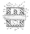
先ず、図1及び図2には、本発明の第一の実施形態としての自動車用エンジンマウント10が、示されている。このエンジンマウント10は、軸部材としての内筒金具12と外筒部材としての外筒金具14が、互いに同一軸上で径方向に所定距離を隔てて配設されており、これら内外筒金具12,14間に介装された本体ゴム弾性体16によって弾性的に連結されている。そして、内筒金具12と外筒金具14が、図示しない自動車のパワーユニット側とボデー側の各一方にそれぞれ取り付けられることにより、かかるエンジンマウント10が、パワーユニットとボデーの間に介装されて、それらを防振連結せしめるようになっている。
【0026】
より詳細には、内筒金具12は、厚肉の小径円筒形状を有している。また、内筒金具12には、図3及び図4にも示されているように、軸方向中央部分において径方向外方に突出するストッパブロック18が組み付けられている。このストッパブロック18は、リング状部22から径方向外方に向かって突出する一対のストッパ部24,24が対向位置して一体形成された構造とされており、リング状部22の嵌着孔20において、内筒金具12に外嵌固定されている。更にまた、内筒金具12の軸方向両側部分には、それぞれ、突出ブロック26が組み付けられている。
【0027】
かかる突出ブロック26は、全体として円環形状を有しており、その中心孔27において、内筒金具12に外嵌固定されることにより、この突出ブロック26によって、内筒金具12の外周面から径方向外方に向かって所定高さで突出する作用突部が、周方向に連続して形成されている。また、突出ブロック26,26の突出先端部分は、何れも、軸方向外側の隅部が斜めに切り欠かれた形状とされており、これらの切欠面が、それぞれ、内筒金具12の軸方向外方に向かってテーパ状に傾斜した傾斜面28とされている。なお、本実施形態では、突出ブロック26の内筒金具12からの突出高さは、ストッパ部24の突出高さよりも小さく設定されている。また、突出ブロック26の傾斜面28は、突出ブロック26の先端面の全幅の略2/3の範囲で、軸方向断面で略直線となる面形状をもって形成されている。更にまた、かかる傾斜面28の傾斜角度は、マウント要求特性等を考慮して決定されることとなり、例えば、本実施形態では、内筒金具12の中心軸(マウント中心軸)に対する傾斜角度:αが、15°≦α≦35°となるように設定されている。
【0028】
また、ストッパブロック18と突出ブロック26,26は、何れも、少なくとも本体ゴム弾性体16よりも硬質の剛性樹脂材料によって形成されている。そして、例えば、別途形成した内筒金具12をセットせしめた成形型内に樹脂材料を充填して、内筒金具12の外周面上で、それらストッパブロック18と突出ブロック26,26を形成することにより、その形成と同時に内筒金具12に対して固定的に組み付けられている。
【0029】
また一方、内筒金具12の径方向外方には、同一軸上で径方向に所定距離を隔てて金属スリーブ30が配設されている。この金属スリーブ30は、大径の円筒形状を有しており、軸方向中央部分には、一対の窓部32,32が、径方向に対向位置して設けられている。換言すれば、かかる金属スリーブ30は、同一軸上に所定距離を隔てて配設された一対の円環状部34,34が、それらの軸方向対向面間に跨がって延びる一対の連結部36,36によって相互に連結,一体化されており、一対の連結部36,36が径方向に対向位置させられていることにより、それら連結部36,36の周方向両側間において一対の窓部32,32が設けられた構造とされている。そして、これらの窓部32,32が、一対のストッパ部24,24の突出方向外方に位置せしめられるように、金属スリーブ30が内筒金具12に対して位置決めされている。
【0030】
そして、これら内筒金具12と金属スリーブ30の径方向対向面間に、本体ゴム弾性体16が介装されている。即ち、本体ゴム弾性体16は、全体として大径の厚肉円筒形状を有しており、その内周面に内筒金具12が加硫接着されると共に、外周面に金属スリーブ30が加硫接着されることによって、それら内筒金具12と金属スリーブ30を有する一体加硫成形品とされているのである。
【0031】
また、本体ゴム弾性体16には、軸方向中央部分において、周方向に連続して延びる幅広凹溝形状のポケット部38が形成されている。なお、このポケット部38は、金属スリーブ30における窓部32の開口幅と略同じ幅寸法を有しており、ポケット部38の形成部分では、該ポケット部38を通じて外周面に開口している一方、ポケット部38が形成されていない部分では、連結部36で開口部が覆われたトンネル形状とされている。また、ポケット部38の内部には、ポケット部38の底部から金属スリーブ30の各窓部32に向かって、ストッパ部24が所定高さで突出位置せしめられている。
【0032】
更にまた、本体ゴム弾性体16によって構成されて、ポケット部38の軸方向両側の壁部を構成する側壁部42,42には、それぞれ、内筒金具12側から径方向外方に向かって突出する突出ブロック26が、埋設状態で配設されている。ここにおいて、本実施形態では、突出ブロック26の突出先端面だけでなく傾斜面28も、その全面が、ポケット部38の底面40よりも径方向外方に位置せしめられて、マウント軸方向の投影でポケット部38に重なるようにされている。また、本実施形態では、突出ブロック26の傾斜面28における有効幅:bの側壁部42の幅:Bに対する比:b/Bが、略1/2となるように、傾斜面28の幅寸法が設定されている。
【0033】
なお、突出ブロック26の突出高さは、特に限定されるものでないが、余り高くすると側壁部42のばね剛性に与える影響が大きいことから、本実施形態では、突出ブロック26の突出高さが、側壁部42の高さ寸法の略1/3となるように設定されている。
【0034】
さらに、このような一体加硫成形品に対して、外筒金具14が外挿されて、金属スリーブ30の外周面に嵌着固定されている。この外筒金具14は、薄肉の大径円筒形状を有しており、内周面には、略全面に亘って薄肉のシールゴム層44が形成されて加硫接着されている。そして、かかる外筒金具14は、金属スリーブ30に外挿されて、該金属スリーブ30に対して、絞り加工により嵌着固定されると共に、軸方向両端部がかしめ固定されることにより、固定的に組み付けられている。なお、外筒金具14と金属スリーブ30の嵌着面は、シールゴム層44が挟圧されて流体密にシールされている。
【0035】
このように外筒金具14が組み付けられることにより、金属スリーブ30の窓部32,32が流体密に覆蓋されて、ポケット部38が密封されており、それによって、所定の非圧縮性流体が封入された受圧室46が、全体として円環形状をもって形成されている。なお、封入流体としては、水やアルキレングリコール,ポリアルキレングリコール,シリコーン油等が何れも採用され得、特に本実施形態では、流体の共振作用に基づく防振効果が有効に発揮されるように、粘度が0.1Pa・s以下の低粘性流体が好適に採用される。また、非圧縮性流体の封入は、例えば、一体加硫成形品に対する外筒金具14の組付けを非圧縮性流体中で行うこと等によって、有利に為され得る。
【0036】
このような構造とされたエンジンマウント10においては、径方向の振動が入力されると、内外筒金具12,14が相対的に偏心して受圧室46の容積が周方向で相対的に変化せしめられることにより、受圧室46内で流体の流動が生ぜしめられるのであり、以て、かかる流体の共振作用等の流動作用に基づいて、防振効果が発揮されることとなる。また、そこにおいて、本実施形態では、受圧室46が周方向全周に亘って充分に大きな断面積をもって形成されて、流体の流路断面積が有利に確保されていることから、流体の共振作用に基づいて低動ばね効果が発揮される周波数域が充分に高周波数域にチューニングされ得て、例えば、高速こもり音等の高周波振動に対する防振効果が極めて有効に発揮されるのである。
【0037】
また、径方向の振動入力時には、内外筒金具12,14間で、側壁部42,42に対して径方向の荷重が入力されることとなり、圧縮変形せしめられる側壁部42,42間で受圧室46に内圧が生ぜしめられて、受圧室46内での周方向の流体流動が惹起されることとなるが、その際、側壁部42に対する内周側の荷重作用面の一部が傾斜面28によって構成されていることから、軸方向外方に向かう分力が生じて、側壁部42に対し、軸方向斜め外方(傾斜面28に垂直な方向)に向かって力が及ぼされることとなる。そのために、側壁部42に対して、軸方向外方への膨出変形が積極的に生ぜしめられるのであり、その分、側壁部42の径方向圧縮変形時における、該側壁部42の受圧室46内方への膨出変形量が小さく抑えられる。
【0038】
それ故、径方向の振動入力時に受圧室46に生ぜしめられる容積変化乃至は内圧変動が小さくなって流体流動量が減少し、流体マスの減少に伴ってチューニング周波数がより高周波数域に有利に設定可能とされると共に、かかるチューニク周波数域よりも低い周波数域の広い範囲に亘って、受圧室46の内圧上昇等に伴う高動ばね現象が軽減乃至は防止されて、低動ばね化による防振性能の向上が図られ得るのである。
【0039】
しかも、傾斜面28の分力作用により側壁部42の受圧室46内方への膨出変形量が抑えられて、流体マスの減少により高周波数域へのチューニングが容易となることから、本体ゴム弾性体16自体のばね特性を軟らかく設定することが可能となるのであり、それによっても、広い周波数域に亘って低動ばね化による防振性能の向上が図られ得るのである。
【0040】
また、かかるエンジンマウント10においては、振動荷重の入力時に、傾斜面28の分力作用により側壁部42の受圧室46内方への膨出変形量が抑えられることによって、低動ばね化が達成されるものであることから、静的ばね定数を有利に確保することが可能であるといった利点もある。
【0041】
なお、本実施形態では、特に大きな荷重が入力される径方向にストッパ部24,24が突設されており、これらストッパ部24,24の外筒金具14に対する当接によって、大荷重入力時における内外筒金具12,14の相対的変位量や本体ゴム弾性体16の弾性変形量が制限されるようになっている。
【0042】
次に、図5及び図6には、本発明の別の実施形態としてのエンジンマウント50が、示されている。なお、本実施形態では、前記第一の実施形態としてのエンジンマウント10と同様な構造とされた部材および部位について、それぞれ、図面中に、第一の実施形態と同一の符号を付することにより、その詳細な説明を省略する。
【0043】
すなわち、本実施形態としてのエンジンマウント50にあっては、本体ゴム弾性体16に設けられたポケット部38内において、内筒金具12と金属スリーブ30の径方向対向面間を連結する一対の隔壁部52,52が、ストッパ部24,24の突出方向に直交する径方向両側で軸方向に連続して、それぞれ、本体ゴム弾性体16により一体形成されている。要するに、これらの隔壁部52,52は、金属スリーブ30における連結部36,36と内筒金具12との径方向対向面間に跨がって設けられており、これらの連結部36,36によって、ポケット部38の内部ひいては受圧室46の内部が周方向に二分されることにより、それぞれストッパ部24,24の突出方向両側に位置して、内筒金具12を挟んで径方向に対向位置せしめられた一対のポケット部38a,38bと一対の受圧室46a,46bが形成されているのである。
【0044】
また、金属スリーブ30の連結部36,36は、それぞれ、径方向内方に凹陥されており、以て、これらの連結部36,36によって、外周面上に開口して周方向に延び、両ポケット部38a,38bの開口部の周方向端部間を相互に連通する溝状の凹部54,54が形成されている。更に、各凹部54には、本体ゴム弾性体16がまわされて充填されていると共に、この充填されたゴム弾性体に対して、凹部54の軸方向中央部分を周方向に延びる凹溝56が形成されている。そして、これらの凹溝56,56が、外筒金具14で覆蓋されることによって、一対の受圧室46a,46bを相互に連通して、それら両受圧室46a,46b間での流体流動を許容するオリフィス通路58が形成されている。
【0045】
一方、内筒金具12の軸方向両側に外嵌固定された突出ブロック26は、図7及び図8にも示されているように、径方向一方向で対向位置する両側部分60,60が一定幅でカットされて突出高さが小さくされており、それらの突出高さが小さくされた部分が、隔壁部52,52の形成部分に対応するように、周方向に位置決めされている。
【0046】
このような構造とされたエンジンマウント50においては、内外筒金具12,14間に径方向の振動荷重が入力されると、各受圧室46a,46b内での流体の流動作用に基づいて高周波振動に対する低動ばね効果が発揮されると共に、各受圧室46a,46bの側壁部42の受圧室46内方への膨出変形量が、突出ブロック26の傾斜面28の分力作用で抑えられることにより、中乃至高周波数域の振動に対しても低動ばね化が図られることとなり、以て、前記第一の実施形態におけるエンジンマウントと同様、広い周波数域の入力振動に対して良好なる防振効果が発揮され得るのである。
【0047】
しかも、内外筒金具12,14間に対して、受圧室46a,46bの対向方向に低周波大振幅振動が入力されると、それら受圧室46a,46b間で生ぜしめられる相対的な内圧変動に基づいて、オリフィス通路58,58を通じての流体流動が生ぜしめられることとなる。そして、これらのオリフィス通路58,58は、通路長さ:Lと通路断面積:Aの比(A/L)が小さいことから、オリフィス通路58,58を通じて流動する流体の共振作用に基づいて、低周波振動に対して減衰効果等の有効な防振効果が発揮され得るのである。
【0048】
また、特に本実施形態では、隔壁部52,52の形成部位において、突出ブロック26の突出高さが低くされていることから、該突出ブロック26の傾斜面28によって受圧室46a,46bの各側壁部42に及ぼされる上述の如き分力作用は充分に確保しつつ、隔壁部52,52を含む本体ゴム弾性体16の体積が有利に確保され得て、応力集中等が軽減乃至は防止されることにより、良好なる耐久性を得ることが出来るといった利点もある。
【0049】
以上、本発明の実施形態について詳述してきたが、本発明は、上述の具体的記載や以下の実施例の記載によって限定的に解釈されるものでなく、本発明は、当業者の知識に基づいて種々なる変更,修正,改良等を加えた態様において実施され得るものであることは、言うまでもない。
【0050】
例えば、第一の実施形態におけるエンジンマウント10では、金属スリーブ30において、連結部36,36を設けることなく、一対の円環状部34,34からなる分割体構造を採用することも可能である。
【0051】
また、第一及び第二の実施形態におけるエンジンマウント10,50において、ストッパブロック18は、必ずしも設ける必要はない。
【0052】
また、第二の実施形態におけるエンジンマウント50において、一方の受圧室46bに代えて、壁部の一部がダイヤフラム等からなる可撓性膜で構成されて容積変化が容易に許容される平衡室を採用することも可能である。
【0053】
また、第一及び第二の実施形態におけるエンジンマウント10,50において、内筒金具12または外筒金具14に支持されて、受圧室46内において振動入力方向に直交する方向に広がる傘状部材を設けることにより、受圧室46内に流体流路を積極的に形成せしめて、高周波振動に対する防振性能の更なる向上を図ること等も可能である。
【0054】
また、第一及び第二の実施形態におけるエンジンマウント10,50において、突出ブロック26を内筒金具12に一体形成することも可能である。
【0055】
加えて、第一及び第二の実施形態では、低粘性流体を受圧室に封入せしめて、流体の共振作用に基づいて防振効果を得るようにしたマウントについて説明したが、その他、高粘性流体を受圧室に封入せしめて、流体のずり剪断応力等に基づいて防振効果を得るようにしたマウントに対して本発明を適用することも可能である。
【0056】
【実施例】
前記第一の実施形態として図1及び図2に示されたエンジンマウント10と同一構造のマウントを実施例として製作し、絶対ばね定数の周波数特性を実測した結果を、実施例として、図9に示す。
【0057】
なお、かかる実験は、内外筒金具12,14間に何等の初期荷重を及ぼすことなく、±0.5mmの振幅の振動を、内外筒金具12,14間におけるストッパ部24,24の突出方向に入力することによって行った。
【0058】
また、比較例として、突出ブロック26,26の突出先端面(外周面)の全面を軸方向に広がる平坦面として、傾斜面28が形成されていない構造のマウントを製作し、かかるマウントについても、上記実施例と同じ実験を行った。その結果を、図9において、比較例として併せ示す。
【0059】
かかる図9に示されているように、突出ブロック26に傾斜面28を形成した実施例のマウントにおいては、傾斜面が形成されていない比較例のマウントに比して、流体の流動作用に基づく防振効果のピークがより高周波数域(500Hz以上)に設定されていると共に、それよりも低周波側の広い周波数域(50〜500Hz程度)に亘って、低動ばね化が達成されている。そして、このことから、実施例のマウントにおける優れた防振性能が明らかに認められる。
【0060】
【発明の効果】
上述の説明から明らかなように、本発明に従う構造とされた流体封入式筒型マウントにおいては、軸部材と外筒部材の間への振動荷重入力時に、作用突部の傾斜面における分力作用により側壁部が軸方向外方に向かって積極的に膨出変形せしめられて、該側壁部の受圧室内方への膨出変形量が抑えられることから、受圧室の内圧変動量乃至は流体流動量が低減されるのであり、それによって、流体の流動作用に基づく低動ばね効果が有効に発揮される高周波域のチューニング点だけでなく、かかるチューニング点よりも低周波側の広い周波数域に亘って動ばね定数が低減されて、優れた防振効果が発揮されるのである。
【図面の簡単な説明】
【図1】本発明の第一の実施形態としてのエンジンマウントを示す縦断面図であって、図2におけるI−I断面に相当する図である。
【図2】図1におけるII−II断面図である。
【図3】図1に示されたエンジンマウントを構成する組立部品図であって、図4におけるIII −III 断面に相当する図である。
【図4】図3における左側面図である。
【図5】本発明の別の実施形態としてのエンジンマウントを示す縦断面図であって、図6におけるV−V断面に相当する図である。
【図6】図5におけるVI−VI断面図である。
【図7】図5に示されたエンジンマウントを構成する組立部品図であって、図8におけるVII −VII 断面に相当する図である。
【図8】図7における左側面図である。
【図9】本発明の実施例としてのマウントについて、絶対ばね定数の周波数特性を実測した結果を、比較例と共に示すグラフである。
【符号の説明】
10,50 エンジンマウント
12 内筒金具
14 外筒金具
16 本体ゴム弾性体
26 突出ブロック
28 傾斜面
42 側壁部
46 受圧室[0001]
【Technical field】
The present invention relates to a cylindrical mount used as an anti-vibration bush, an anti-vibration mount, and the like, and in particular, has an anti-vibration effect against vibration input in a direction perpendicular to the mount axis based on the flow action of a fluid sealed inside. The present invention relates to a fluid-filled cylindrical mount to be exhibited.
[0002]
[Prior art]
As a type of vibration isolator that is interposed between members to be vibration-isolated, conventionally, a shaft bracket and an outer cylinder bracket arranged concentrically or eccentrically at a predetermined distance from each other are interposed between them. Cylindrical shape that exerts an anti-vibration effect against vibration in the direction perpendicular to the axis, which is mainly input between the shaft bracket and the outer tube bracket, by elastically connecting with the interposed rubber elastic body. Mounts are known and widely used as suspension bushes for automobiles, engine mounts, differential mounts, body mounts, and the like. Also, in recent years, in order to cope with the demand for higher vibration isolation performance, a part of the wall part is made of rubber elastic body between the shaft bracket and outer cylinder bracket, and incompressible fluid is enclosed inside Accordingly, a fluid-filled cylindrical mount that forms a pressure receiving chamber to which vibration is input and obtains an anti-vibration effect based on a fluid flow action in the pressure receiving chamber is also employed.
[0003]
By the way, in the fluid-filled cylindrical mount, the region where the vibration isolation effect based on the fluid action such as the resonance action of the fluid can be effectively exerted against the input vibration is the spring constant of the main rubber elastic body or the disconnection of the fluid flow path. There is a tendency to be limited to a relatively narrow frequency range determined by the area and length. For example, in order to obtain vibration insulation characteristics based on the low dynamic spring effect due to the fluid flow action against input vibrations in the high frequency range, the fluid passage is enlarged or a rubber material with hard spring characteristics is adopted. For example, it is necessary to tune to a high frequency range.
[0004]
However, the larger the fluid flow path, the larger the mount size, which is difficult when the mounting space is limited, and the larger the mount size, the larger the free length of the rubber elastic body. Eventually, it is necessary to secure a required static spring constant by employing a rubber material having a hard spring characteristic.
[0005]
If a rubber material with a hard spring characteristic is used, the dynamic spring constant increases, and the vibration isolation performance as a whole decreases.In particular, the dynamic spring constant extends over a wide frequency range lower than the tuning frequency. Therefore, for example, when anti-vibration performance is tuned in a high frequency range of about 500 Hz, a sufficient vibration insulation effect is obtained in a frequency range of about 100 to 400 Hz on the lower frequency side. There was a problem that it was difficult.
[0006]
[Solution]
Here, the present invention has been made in the background as described above, and the problem to be solved is to prevent a significant increase in the mounting size and the hardness of the rubber material. An increase in the dynamic spring constant on the lower frequency side than the tuning frequency range when tuning the vibration performance to a high frequency range can be advantageously suppressed, and a good vibration isolation effect can be exhibited over a wide frequency range. An object of the present invention is to provide a fluid-filled cylindrical mount having an improved structure.
[0007]
[Solution]
In order to solve such a problem, the invention described in claim 1 includes a shaft member and an outer cylinder member disposed at a predetermined distance on the outer side of the shaft member. While being connected by the interposed main rubber elastic body, a part of the wall portion is constituted by the main rubber elastic body between the shaft member and the outer cylinder member, and an incompressible fluid is sealed inside. A pressure receiving chamber into which vibration is input is formed, and an anti-vibration effect is obtained based on the fluid flow action in the pressure receiving chamber. Vibration can be input in the direction perpendicular to the mount axis. In the fluid-filled cylindrical mount, at least one of the side wall portions on both sides in the mount axial direction of the pressure receiving chamber constituted by the main rubber elastic body is inserted into the side wall portion from at least one side of the shaft member and the outer cylindrical member. A projecting projection projecting on the tip of the working projecting portion toward the outer side of the mount axis. So that the height gradually decreases A fluid-filled cylindrical mount is characterized in that it forms a substantially inclined surface and at least a part of the inclined surface overlaps the pressure receiving chamber as projected in the mount axis direction.
[0008]
In the fluid-filled cylindrical mount having the structure according to the first aspect of the present invention, the vibration load in the direction perpendicular to the axis input between the shaft member and the outer cylinder member is constituted by the main rubber elastic body. When exerted on the axial side wall portion of the pressure receiving chamber, the inclined surface of the action protrusion effectively generates a component force that causes the side wall portion to bulge outward. This component force increases the outward bulging deformation amount in the axial side wall portion of the pressure receiving chamber, thereby reducing the volume change amount of the pressure receiving chamber and the fluid flow amount at the time of vibration input. As a result of the smaller fluid flow mass, the vibration isolation characteristics can be advantageously tuned to a high frequency range without the spring characteristics of the main rubber elastic body being significantly hardened.
[0009]
Therefore, in such a fluid-filled cylindrical mount, even when tuning the vibration isolation characteristics to a high frequency range, the low dynamic spring characteristics can be advantageously set with respect to the main rubber elastic body. The anti-vibration performance is exhibited over a wide frequency range on the lower frequency side.
[0010]
In addition, the action protrusions that form the inclined surface only need to be higher in rigidity than at least the main rubber elastic body, and those made of metal or synthetic resin may be employed. In addition, the inclined surface may be any shape that can generate a component force that causes the side wall portion to bulge outwardly when a vibration load in a direction perpendicular to the axis is input. It may be a curved inclined surface or an uneven inclined surface.
[0011]
In addition, it is not necessary to make the entire surface of the projecting tip of the working projection as an inclined surface. For example, the outer corner of the projecting tip of the working projecting portion is cut off obliquely, and a part of the projecting tip is tilted. It can also be a surface.
[0012]
Furthermore, the inclined surface of the working protrusion does not need to be formed over the entire circumference of the pressure receiving chamber in the side wall portions on both sides in the mount axis direction of the pressure receiving chamber, and is partially located in the side wall portion of the pressure receiving chamber. It may be formed as follows.
[0013]
In addition, Preferably, the action protrusion part which protrudes toward the outer cylinder member side from the shaft member side is employ | adopted. If such a configuration of the action protrusion is employed, the mount productivity can be improved.
[0014]
Preferably, the inclined surface of the working protrusion is formed over the entire circumference of the pressure receiving chamber on the side wall portions on both sides of the pressure receiving chamber in the mount axis direction, and is opposed to the mount axis direction. By adopting such a configuration of the inclined surface, a component force that bulges and deforms the side wall portion outward when a vibration load in a direction perpendicular to the axis is input can be generated more advantageously.
[0015]
Still preferably, the width of the inclined surface of the working protrusion is 1/5 or more, more preferably, 1/3 of the dimension of the side wall portion in the mount axis direction with respect to the side wall portions on both sides in the mount axis direction of the pressure receiving chamber. It sets so that it may become above. Preferably, the inclination angle of the inclined surface of the operating protrusion with respect to the mount axis direction line is set to 10 ° to 60 °, more preferably 15 ° to 35 °. If such a configuration related to the width and angle of the inclined surface is adopted, a component force that bulges and deforms the side wall portion outward when a vibration load in the direction perpendicular to the axis is input while securing the rigidity of the mount spring in the direction perpendicular to the axis. Can be effectively obtained.
[0016]
On the other hand, according to a second aspect of the present invention, in the fluid-filled cylindrical mount having the structure according to the first aspect of the present invention, the pressure receiving chamber is continuously formed in the circumferential direction, and the working protrusion Is formed in an annular shape, and the inclined surface is continuously formed in the circumferential direction in the side wall portion of the pressure receiving chamber.
[0017]
In the fluid-filled cylindrical mount having the structure according to the invention described in claim 2, the vibration isolating effect based on the fluid flow action is effective at the time of vibration input in a plurality of different mount axis perpendicular directions. In addition, the side wall portion of the pressure receiving chamber is bulged and deformed outward, and an effective anti-vibration effect is exhibited in a wide frequency range lower than the tuning frequency.
[0018]
In particular, if the cross-sectional area of the pressure receiving chamber is substantially constant over the entire circumferential direction, it is possible to obtain a more advantageous vibration-proofing effect based on the fluid flow action, and any mount axis perpendicular direction Therefore, a certain vibration isolating effect based on the fluid flow action can be effectively exerted against the input vibration.
[0019]
According to a third aspect of the present invention, in the fluid-filled cylindrical mount having the structure according to the first or second aspect of the present invention, a gap between the shaft member and the outer cylindrical member is defined by the main rubber elastic body. By partitioning in the circumferential direction, the pressure receiving chamber is partially formed between the shaft member and the outer cylinder member in the circumferential direction, and the shaft member and the outer cylinder are not located in the pressure receiving chamber. A sub liquid chamber in which an incompressible fluid is sealed is formed between the members, and fluid flow is generated through an orifice passage communicating the pressure receiving chamber and the sub liquid chamber when vibration is input. This is a feature.
[0020]
In the fluid-filled cylindrical mount having the structure according to the invention described in claim 3, for example, an anti-vibration effect against low-frequency vibration can be obtained based on the fluid action of the fluid that is caused to flow through the orifice passage. It becomes possible. At that time, the structure of the orifice passage is appropriately set so as to ensure the required passage length and cross-sectional area according to the required anti-vibration characteristics, for example, a length of one or more rounds in the mount circumferential direction. It is also possible to form an orifice passage. In addition, when the pressure receiving chamber is partially formed in the circumferential direction, the low dynamic spring effect based on the fluid flow action in the high frequency region may not always be clearly recognized. The low dynamic spring effect over a wide frequency range as described above, which is exhibited by bulging and deforming the side wall portion by the action of the component force, can be effectively exhibited. Although not necessarily limited, the orifice passage communicating the pressure receiving chamber and the sub liquid chamber generally has a frequency range in which the vibration isolation effect based on the fluid action of the fluid flowing inside the pressure passage is exerted on the slope. Tuning is performed so that the low dynamic spring effect based on the action of the component force by the surface is on the lower frequency side than the frequency region where the effect is exhibited.
[0021]
In the invention according to claim 3, even if the sub liquid chamber has a structure in which an internal pressure fluctuation that is increased and decreased is opposite to that of the pressure receiving chamber when vibration is input between the shaft member and the outer cylinder member. Alternatively, a structure in which a part of the wall portion is formed of a flexible film and volume change is easily allowed may be used.
[0022]
According to a fourth aspect of the present invention, in the fluid-filled cylindrical mount having the structure according to any of the first to third aspects, the working protrusion having the inclined surface is disposed. The side wall portion of the pressure receiving chamber has a shape that causes a bending deformation that protrudes outward from the pressure receiving chamber by inputting a compressive load perpendicular to the mount axis.
[0023]
In the fluid-filled cylindrical mount having the structure according to the invention described in claim 4, the side wall portion of the pressure receiving chamber itself bulges outwardly at the side wall portion when a vibration load is input. Large amount is secured. And the elastic deformation characteristic of this side wall part itself acts in addition to the action of the component force by the inclined surface, and as described above, the low dynamic spring effect over a wide frequency range is achieved more advantageously, A better anti-vibration effect can be realized. In addition, the shape that causes a bending deformation that protrudes outward from the pressure receiving chamber by the input of a compressive load in the direction perpendicular to the mount axis in the side wall is a shape that generates a bending moment due to the compressive load in the direction perpendicular to the mount axis. For example, it can be advantageously realized by forming the inner surface or outer surface in the axial direction of the side wall portion with a curved surface shape toward the outside of the pressure receiving chamber in the mount longitudinal section.
[0024]
DETAILED DESCRIPTION OF THE INVENTION
Hereinafter, in order to clarify the present invention more specifically, embodiments of the present invention will be described in detail with reference to the drawings.
[0025]
First, FIGS. 1 and 2 show an
[0026]
More specifically, the inner cylinder fitting 12 has a thick small diameter cylindrical shape. Further, as shown in FIGS. 3 and 4, the inner cylinder fitting 12 is assembled with a
[0027]
The projecting
[0028]
The
[0029]
On the other hand, a
[0030]
The main rubber
[0031]
The main rubber
[0032]
Furthermore, it is constituted by the main rubber
[0033]
The protruding height of the protruding
[0034]
Further, the outer cylinder fitting 14 is extrapolated to such an integrally vulcanized molded product, and is fitted and fixed to the outer peripheral surface of the
[0035]
By assembling the
[0036]
In the
[0037]
Further, when a vibration is input in the radial direction, a radial load is input to the
[0038]
Therefore, the volume change or internal pressure fluctuation generated in the
[0039]
In addition, the amount of bulging deformation of the
[0040]
In the
[0041]
In the present embodiment, the
[0042]
Next, FIGS. 5 and 6 show an
[0043]
That is, in the
[0044]
Further, the connecting
[0045]
On the other hand, as shown in FIGS. 7 and 8, the protruding
[0046]
In the
[0047]
In addition, when low-frequency large-amplitude vibration is input in the opposing direction of the
[0048]
In particular, in the present embodiment, since the protruding height of the protruding
[0049]
Although the embodiments of the present invention have been described in detail above, the present invention is not construed as being limited by the above-described specific description or the description of the following examples. Needless to say, the present invention can be implemented in a mode in which various changes, modifications, improvements, and the like are added.
[0050]
For example, in the
[0051]
In the engine mounts 10 and 50 in the first and second embodiments, the
[0052]
Further, in the
[0053]
Further, in the engine mounts 10 and 50 in the first and second embodiments, an umbrella-shaped member that is supported by the inner cylinder fitting 12 or the outer cylinder fitting 14 and extends in the direction perpendicular to the vibration input direction in the
[0054]
Further, in the engine mounts 10 and 50 in the first and second embodiments, the protruding
[0055]
In addition, in the first and second embodiments, the mount has been described in which the low-viscosity fluid is sealed in the pressure-receiving chamber so as to obtain the vibration-proofing effect based on the resonance action of the fluid. It is also possible to apply the present invention to a mount that is sealed in a pressure receiving chamber so as to obtain a vibration isolation effect based on a shear shear stress or the like of the fluid.
[0056]
【Example】
As the first embodiment, a mount having the same structure as the
[0057]
In this experiment, vibrations with an amplitude of ± 0.5 mm are applied in the protruding direction of the
[0058]
Further, as a comparative example, a mount having a structure in which the
[0059]
As shown in FIG. 9, the mount of the embodiment in which the
[0060]
【The invention's effect】
As is clear from the above description, in the fluid-filled cylindrical mount structured according to the present invention, the component force action on the inclined surface of the acting protrusion is applied when a vibration load is input between the shaft member and the outer cylindrical member. As a result, the side wall is positively bulged and deformed outward in the axial direction, and the amount of bulging deformation of the side wall into the pressure receiving chamber is suppressed. Therefore, not only the tuning point in the high frequency range where the low dynamic spring effect based on the fluid flow action is effectively exhibited, but also in a wide frequency range on the low frequency side from the tuning point. As a result, the dynamic spring constant is reduced, and an excellent anti-vibration effect is exhibited.
[Brief description of the drawings]
FIG. 1 is a longitudinal sectional view showing an engine mount as a first embodiment of the present invention, which corresponds to a cross section taken along line II in FIG.
FIG. 2 is a cross-sectional view taken along the line II-II in FIG.
3 is an assembly part diagram constituting the engine mount shown in FIG. 1 and corresponding to a III-III cross section in FIG. 4;
4 is a left side view in FIG. 3. FIG.
5 is a longitudinal sectional view showing an engine mount as another embodiment of the present invention, which corresponds to a VV section in FIG. 6; FIG.
6 is a sectional view taken along line VI-VI in FIG.
7 is an assembly part diagram constituting the engine mount shown in FIG. 5 and corresponding to a VII-VII cross section in FIG. 8;
FIG. 8 is a left side view in FIG.
FIG. 9 is a graph showing the results of actual measurement of the frequency characteristics of the absolute spring constant for the mount as the embodiment of the present invention, together with a comparative example.
[Explanation of symbols]
10,50 Engine mount
12 Inner tube bracket
14 Outer tube bracket
16 Body rubber elastic body
26 Protruding block
28 Inclined surface
42 Side wall
46 Pressure receiving chamber
Claims (5)
前記本体ゴム弾性体で構成された前記受圧室におけるマウント軸方向両側の側壁部の少なくとも一方に、前記軸部材および前記外筒部材の少なくとも一方の側から該側壁部内に突出する作用突部を設けて、該作用突部の先端面にマウント軸方向外方に向かって漸次高さが低くなるように実質的に傾斜する傾斜面を形成すると共に、該傾斜面の少なくとも一部がマウント軸方向の投影で該受圧室に重なるようにしたことを特徴とする流体封入式筒形マウント。The shaft member and the outer cylinder member disposed at a predetermined distance outside the shaft member are connected by a main rubber elastic body interposed therebetween, while the shaft member and the outer cylinder member A part of the wall portion is made of the rubber elastic body of the main body, and a non-compressible fluid is sealed inside to form a pressure receiving chamber into which vibration is input, so that the fluid flows in the pressure receiving chamber. In a fluid-filled cylindrical mount that allows vibration to be input in the direction perpendicular to the mount axis, so as to obtain an anti-vibration effect based on
At least one of the side wall portions on both sides in the mount axial direction of the pressure receiving chamber formed of the main rubber elastic body is provided with an action protrusion that protrudes into the side wall portion from at least one side of the shaft member and the outer cylinder member. An inclined surface that is substantially inclined so as to gradually decrease in height toward the outer side in the mount axis direction is formed on the tip surface of the action protrusion, and at least a part of the inclined surface extends in the mount axis direction. A fluid-filled cylindrical mount, wherein the pressure-receiving chamber overlaps with a projection.
Priority Applications (1)
| Application Number | Priority Date | Filing Date | Title |
|---|---|---|---|
| JP23512296A JP3627397B2 (en) | 1996-09-05 | 1996-09-05 | Fluid filled cylindrical mount |
Applications Claiming Priority (1)
| Application Number | Priority Date | Filing Date | Title |
|---|---|---|---|
| JP23512296A JP3627397B2 (en) | 1996-09-05 | 1996-09-05 | Fluid filled cylindrical mount |
Publications (2)
| Publication Number | Publication Date |
|---|---|
| JPH1078075A JPH1078075A (en) | 1998-03-24 |
| JP3627397B2 true JP3627397B2 (en) | 2005-03-09 |
Family
ID=16981385
Family Applications (1)
| Application Number | Title | Priority Date | Filing Date |
|---|---|---|---|
| JP23512296A Expired - Fee Related JP3627397B2 (en) | 1996-09-05 | 1996-09-05 | Fluid filled cylindrical mount |
Country Status (1)
| Country | Link |
|---|---|
| JP (1) | JP3627397B2 (en) |
Families Citing this family (1)
| Publication number | Priority date | Publication date | Assignee | Title |
|---|---|---|---|---|
| JP2005254663A (en) | 2004-03-12 | 2005-09-22 | Toshiba Tec Corp | Wire dot printer head and wire dot printer |
-
1996
- 1996-09-05 JP JP23512296A patent/JP3627397B2/en not_active Expired - Fee Related
Also Published As
| Publication number | Publication date |
|---|---|
| JPH1078075A (en) | 1998-03-24 |
Similar Documents
| Publication | Publication Date | Title |
|---|---|---|
| JP3702683B2 (en) | Fluid filled vibration isolator | |
| US4971456A (en) | Fluid-filled elastic center bearing mount | |
| JPH0430442Y2 (en) | ||
| US4921229A (en) | Fluid-filled elastic center bearing mount | |
| EP1870613B1 (en) | Vibration isolator | |
| JP3580279B2 (en) | Fluid-filled cylindrical vibration isolator | |
| US4893798A (en) | Fluid-filled elastic bushing having means for limiting elastic deformation of axial end portions of elastic member defining pressure-receiving chamber | |
| JPH0330736B2 (en) | ||
| JPS61206838A (en) | Bush assembling body with fluid | |
| US5213313A (en) | Fluid-filled cylindrical elastic mount having lateral and radial elastic walls for desired axial and diametric spring characteristics | |
| JP3603631B2 (en) | Fluid-filled anti-vibration device | |
| JP2002327788A (en) | Fluid-filled vibration isolator | |
| JPH0555739B2 (en) | ||
| JPH10132015A (en) | Fluid-filled cylindrical vibration isolator | |
| JP3627397B2 (en) | Fluid filled cylindrical mount | |
| US6669181B2 (en) | Vibration isolating apparatus | |
| JP3427593B2 (en) | Fluid-filled cylindrical mount | |
| JP4270049B2 (en) | Fluid filled vibration isolator | |
| JP3736155B2 (en) | Fluid-filled cylindrical vibration isolator and manufacturing method thereof | |
| JPH0545810B2 (en) | ||
| JP2827846B2 (en) | Fluid-filled bush | |
| JPH0523866Y2 (en) | ||
| JP3998491B2 (en) | Fluid filled anti-vibration bush | |
| JP2010138938A (en) | Fluid-filled cylindrical vibration damper | |
| JPH07151182A (en) | Fluid filled anti-vibration bush |
Legal Events
| Date | Code | Title | Description |
|---|---|---|---|
| A977 | Report on retrieval |
Free format text: JAPANESE INTERMEDIATE CODE: A971007 Effective date: 20040622 |
|
| A131 | Notification of reasons for refusal |
Free format text: JAPANESE INTERMEDIATE CODE: A131 Effective date: 20040720 |
|
| A521 | Written amendment |
Free format text: JAPANESE INTERMEDIATE CODE: A523 Effective date: 20040917 |
|
| TRDD | Decision of grant or rejection written | ||
| A01 | Written decision to grant a patent or to grant a registration (utility model) |
Free format text: JAPANESE INTERMEDIATE CODE: A01 Effective date: 20041116 |
|
| A61 | First payment of annual fees (during grant procedure) |
Free format text: JAPANESE INTERMEDIATE CODE: A61 Effective date: 20041129 |
|
| R150 | Certificate of patent (=grant) or registration of utility model |
Free format text: JAPANESE INTERMEDIATE CODE: R150 |
|
| FPAY | Renewal fee payment (prs date is renewal date of database) |
Free format text: PAYMENT UNTIL: 20081217 Year of fee payment: 4 |
|
| FPAY | Renewal fee payment (prs date is renewal date of database) |
Free format text: PAYMENT UNTIL: 20081217 Year of fee payment: 4 |
|
| FPAY | Renewal fee payment (prs date is renewal date of database) |
Free format text: PAYMENT UNTIL: 20091217 Year of fee payment: 5 |
|
| FPAY | Renewal fee payment (prs date is renewal date of database) |
Free format text: PAYMENT UNTIL: 20101217 Year of fee payment: 6 |
|
| FPAY | Renewal fee payment (prs date is renewal date of database) |
Free format text: PAYMENT UNTIL: 20111217 Year of fee payment: 7 |
|
| FPAY | Renewal fee payment (prs date is renewal date of database) |
Free format text: PAYMENT UNTIL: 20121217 Year of fee payment: 8 |
|
| FPAY | Renewal fee payment (prs date is renewal date of database) |
Free format text: PAYMENT UNTIL: 20131217 Year of fee payment: 9 |
|
| LAPS | Cancellation because of no payment of annual fees |