JP3614657B2 - Image forming apparatus - Google Patents
Image forming apparatus Download PDFInfo
- Publication number
- JP3614657B2 JP3614657B2 JP11592098A JP11592098A JP3614657B2 JP 3614657 B2 JP3614657 B2 JP 3614657B2 JP 11592098 A JP11592098 A JP 11592098A JP 11592098 A JP11592098 A JP 11592098A JP 3614657 B2 JP3614657 B2 JP 3614657B2
- Authority
- JP
- Japan
- Prior art keywords
- image
- unit
- image data
- output
- forming apparatus
- Prior art date
- Legal status (The legal status is an assumption and is not a legal conclusion. Google has not performed a legal analysis and makes no representation as to the accuracy of the status listed.)
- Expired - Fee Related
Links
Images


Description
【0001】
【発明の属する技術分野】
この発明は、接続された複数の画像形成装置、例えばディジタル複写機の出力に関する。
【0002】
【従来の技術】
従来より様々な目的のために、画像信号を出力するイメージスキャナやワードプロセッサ、パーソナルコンピュータなどの複数の画像信号出力手段とそれらの各画像信号によってそれぞれ画像形成を行う複数のプリンタ等の画像形成装置とを組み合わせたシステムが提案されている。
例えば、特開平5−304575号公報記載の発明に見られるように、ディジタル複写機をつなぎ、複写動作のスピードを高めて、短時間で多量の複写を取るシステムが提案されている。
【0003】
【発明が解決しようとする課題】
しかしながら、上記発明では、複数の複写機に同じ動作をさせるため、複写機の状態によって処理時間が異なるという問題点がある。
そこで、本発明の第1の目的は、連結コピーにより、コピー時間の短縮、生産性を向上させるディジタル複写機のネットワークシステムにおいて、コピー機が様々な理由からプリント待ち状態に入っていても、ユーザーに操作待ちさせることのない画像形成装置を提供することである。
本発明の第2の目的は、連結システム上で操作可能なコピー機において、ユーザが定着温度を認識することにより、どのコピー機が一番速く立ち上がるのかを知ることができ、効率的に操作を行える画像形成装置を提供することである。
本発明の第3の目的は、連結システム上で操作可能なコピー機において、ユーザーがプリント待ち所要時間を認識することにより、どのコピー機が一番速く立ち上がるのかを知ることができ、効率的に操作ができる画像形成装置を提供することである。
【0004】
【課題を解決するための手段】
請求項1記載の発明では、原稿の画像データを読み取る画像読取手段と、この画像読取手段で読み取った画像データを記憶する記憶手段と、この記憶手段に記憶された画像データを転写紙に印字する出力手段と、他の画像形成装置と接続して、画像データおよび各種コマンドの送受信を行う接続手段と、前記画像読取手段で読み取った画像データを、前記接続手段を介して、他の画像形成装置で分担して印字出力させる場合、接続機がリロード待ち状態であるか否かを検知する検知手段とこの検知手段による検知の結果、接続機がリロード待ち状態だったとき、定着温度が最もリロード温度に近い接続機を選択する選択手段と、この選択手段により選択された接続機と前記出力手段、各々で出力された枚数を表示する表示手段と、を備えたことにより、前記第1の目的を達成する。
【0005】
請求項2記載の発明では、請求項1記載の発明において、前記表示手段に接続機の定着温度も表示することにより、前記第2の目的を達成する。
【0006】
請求項3記載の発明では、原稿の画像データを読み取る画像読取手段と、この画像読取手段で読み取った画像データを記憶する記憶手段と、この記憶手段に記憶された画像データを転写紙に印字する出力手段と、他の画像形成装置と接続して、画像データおよび各種コマンドの送受信を行う接続手段と、前記画像読取手段で読み取った画像データを、前記接続手段を介して、他の画像形成装置で分担して印字出力させる場合、接続機がリロード待ち状態であるか否かを検知する検知手段と、この検知手段による検知の結果、接続機がリロード待ち状態であったとき、定着温度とイニシャル動作時間からプリント待ち所要時間を割り出し、もっとも所要時間の少ない接続機を選定する選定手段と、この選定手段により選択された接続機と前記出力手段、各々で出力された枚数を表示する表示手段と、を備えたことにより、前記第1の目的を達成する。
【0007】
請求項4記載の発明では、請求項3記載の発明において、前記表示手段に接続機のプリント待ち所要時間を表示することにより、前記第3の目的を達成する。
【0008】
【発明の実施の形態】
以下、本発明の好適な実施の形態を、図1ないし図24を参照して詳細に説明する。
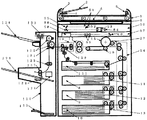
図1は本発明の実施の形態に係る画像形成装置を示した図である。
ADF(自動原稿送り装置)1にある、原稿台2に原稿の画像面を上にして載置された原稿束は、操作部30(図2)上のスタートキー34が押下されると、一番下の原稿から給送ローラ3、給送ベルト4によってコンタクトガラス6上の所定の位置に給送される。読み取りユニット50によってコンタクトガラス6上の原稿の画像データを読み取り後、読み取りが終了した原稿は、給送ベルト4及び排送ローラ5によって排出される。さらに、原稿セット検知7にて原稿台2に次の原稿があることを検知した場合、前原稿と同様にコンタクトガラス6上に給送される。給送ローラ3、給送ベルト4、排送ローラ5はモータによって駆動される。
【0009】
第1トレイ8、第2トレイ9、第3トレイ10に積載された転写紙は、各々第1給紙装置11、第2給紙装置12、第3給紙装置13によって給紙され、縦搬送ユニット14によって感光体15に当接する位置まで搬送される。読み取りユニット50にて読み込まれた画像データは、書き込みユニット57からのレーザによって感光体15に書き込まれ、現像ユニット27を通過することによってトナー像が形成される。そして、転写紙は感光体15の回転と等速で搬送ベルト16によって搬送されながら、感光体15上のトナー像が転写される。その後、定着ユニット17にて画像を定着させ、排紙ユニット18によって後処理装置のフィニシャ120に排出される。
【0010】
後処理装置のフィニシャ120は、本体の排紙ローラによって搬送された転写紙を、通常排紙ローラ123方向と、ステープル処理部方向に導くことができる。分岐偏光板121を上に切り替えることにより、搬送ローラ122を経由して通常排紙トレイ124側に排紙することができる。また、分岐偏光板121を下方向に切り替えることで、搬送ローラ125、127を経由して、ステープル台128に搬送することができる。
ステープル台128に積載された転写紙は、一枚排紙されるごとに紙揃え用のジョガー129によって、紙端面が揃えられ、一部のコピー完了とともにステープラ126によって綴じられる。ステープラ126で綴じられた転写紙群は自重によって、ステープル完了排紙トレイ130に収納される。
【0011】
一方、通常の排紙トレイ124は前後に移動可能な排紙トレイである。前後に移動可能な排紙トレイ124は原稿ごと、あるいは、画像メモリによってソーティングされたコピー部ごとに、前後に移動し、簡易的に排出されてくるコピー紙を仕分けるものである。
転写紙の両面に画像を作像する場合は、各給紙トレイ8〜10から給紙され作像された転写紙を排紙トレイ124側に導かないで、経路切り替えのための分岐爪132を上側にセットすることで、一旦両面給紙ユニット131にストックする。
【0012】
その後、両面給紙ユニット131にストックされた転写紙は再び感光体15に作像されたトナー画像を転写するために、両面給紙ユニット131から再給紙され、経路切り替えのための分岐爪132を下側にセットし、排紙トレイ124に導く。この様に転写紙の両面に画像を作成する場合に両面給紙ユニット131は使用される。
【0013】
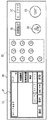
図2は操作部30を示した図である。
この操作部30には、液晶タッチパネル31、テンキー32、クリア/ストップキー33、プリントキー34、モードクリアキー35があり、液晶タッチパネル31には、機能キー37、部数、及び画像形成装置の状態を示すメッセージなどが表示される。
【0014】
図3は操作部30の液晶タッチパネル31の表示例を示した図である。
オペレータが液晶タッチパネル31に表示されたキーにタッチすることで、選択された機能を示すキーが黒く反転する。また、機能の詳細を指定しなければならない場合(例えば変倍であれば変倍値など)は、キーにタッチすることで、詳細機能の設定画面が表示される。このように、液晶タッチパネル31は、ドット表示器を使用しているため、その時の最適な表示をグラフィカルに行うことが可能となる。
図3において左上は「コピーできます」「お待ちください」などのメッセージを表示するメッセージエリア、その右は、セットした枚数を表示するコピー枚数表示部、その下の画像濃度を自動的に調製する自動濃度キー、転写紙を自動選択する自動用紙選択キー、倍率を等倍にセットする等倍キー、コピーを一部ずつページ順にそろえる処理を指定するソートキー、コピーをページごとに仕分けする処理を指定するスタックキー、ソート処理されたものを一部ずつ綴じる処理を指定するステープルキー、拡大/縮小倍率をセットする変倍キー、両面モードを設定する両面キー、綴じ代モードを設定する消去/移動キー、ディジタル複写機のネットワークを介して多量のプリント動作を複数に分けてプリントアウトする連結モードキーである。
選択されているモードはキーが網掛け表示してある。
【0015】
図1を参照して、本実施の形態における画像読み取り手段、および画像を記録面上に潜像形成するまでの動作を説明する。潜像とは感光体面上に画像を光情報に変換して照射することにより生じる電位分布である。
読み取りユニット50は、原稿を載置するコンタクトガラス6と光学走査系で構成されており、光学走査系には、露光ランプ51、第1ミラー52、レンズ53、CCD(光電変換素子)イメージセンサ54等で構成されている。露光ランプ51及び第1ミラー52は図示しない第1キャリッジ上に固定されている。原稿像を読み取るときには、光路長が変わらないように、第1キャリッジと第2キャリッジとが2対1の相対速度で機械的に走査される。この光学走査系は、図示しないスキャナ駆動モータにて駆動される。
【0016】
原稿画像は、CCDイメージセンサ54によって読み取られ、電気信号に変換されて処理される。レンズ53およびCCDイメージセンサ54を図1において左右方向に移動させることにより、画像倍率が変化する。すなわち、指定された倍率に対応してレンズ53およびCCDイメージセンサ54の左右方向に位置が設定される。
書き込みユニット57はレーザ出力ユニット58、結像レンズ59、ミラー60で構成され、レーザ出力ユニット58の内部には、レーザ光源であるレーザダイオード及びモータによって高速で定速回転する回転多面鏡(ポリゴンミラー)が備わっている。
レーザ出力ユニット58より照射されるレーザ光は、低速回転するポリゴンミラーで偏光され、結像レンズ59を通り、ミラー60で折り返され、感光体面上に集光結像する。
【0017】
偏光されたレーザ光は感光体15が回転する方向と直行する方向(主走査方向)に露光走査され、後述する画像処理部のセレクタ64より出力された画像信号のライン単位の記録を行う。感光体15の回転速度と記録密度に対応した所定の周期で主走査を繰り返すことによって、感光体面上に画像(静電潜像)が形成される。
上述のように、書き込みユニット57から出力されるレーザ光が、画像作像系の感光体15に照射される。図示しないが、感光体15の一端近傍のレーザビームを照射される位置に、主走査同期信号を発生するビームセンサが配置されている。この主走査同期信号をもとに主走査方向の画像記録開始タイミングの制御、および後述する画像信号の入出力を行うための制御信号の生成を行う。
【0018】
本実施の形態における画像処理部(画像読み取り部と画像書き込み部)の構成を、図8を参照して説明する。
露光ランプ51から照射された光は原稿面を照射し、原稿面からの反射光を、CCDイメージセンサ54にて結像レンズ(図示せず)により結像、受光して光電変換し、A/Dコンバータ61にてディジタル信号に変換する。ディジタル信号に変換された画像信号は、シェーディング補正62がなされた後、画像処理部63にてMTF(変調伝達関数)補正、γ補正などが行われる。
セレクタ64では、画像信号の送り先を、変倍部71または、画像メモリコントローラ65への切り替えが行われる。変倍部71を経由した画像信号は変倍率に合わせて拡大縮小され、書き込みユニット57に送られる。画像メモリコントローラ65とセレクタ64間は、双方向に画像信号を入出力可能な構成となっている。
【0019】
図8には特に明示していないが、IPU(画像処理部)には、読み取りユニット50から入力される画像データ以外にも外部から供給される画像データ(例えばパーソナルコンピュータなどのデータ処理装置から出力されるデータ)も処理できるよう、複数のデータの入出力の選択を行う機能を有している。
メモリコントローラ65などへの設定や、読み取りユニット50や書き込みユニット57の制御を行うCPU(中央処理装置)68、及びそのプログラムやデータを格納するROM(リード・オンリ・メモリ)69、RAM(ランダム・アクセス・メモリ)70を備えている。さらにCPU68は、メモリコントローラ65を介して、画像メモリ66のデータの書き込み、読み出しが行える。
【0020】
ここで、図10を用いて、セレクタ64における1ページ分の画像信号について説明する。
/FGATEは、1ページの画像データの副走査方向の有効期間を表している。/LSYNCは、1ラインごとの主走査同期信号であり、この信号が立ち上がった後の所定クロックで、画像信号が有効となる。主走査方向の画像信号が有効であることを示す信号が、/LGATEである。これらの信号は、画素クロックVCLKに同期しており、VCLKの1周期に対し1画素のデータが送られてくる。IPU49は、画像入力、出力それぞれに対して別個の/FGATE、/LSYNC、/LGATE、VCLKの発生機構を有しており、様々な画像入出力の組み合わせが実現可能になる。
【0021】
次に、図9を参照して、図8におけるメモリコントローラ65と画像メモリ66の詳細を説明する。
メモリコントローラ65は、入力データセレクタ101、画像合成102、1次圧縮/伸長103、出力データセレクタ104、2次圧縮/伸長105のブロックを有している。各ブロックへの制御データの設定は、CPU68より行われる。図8におけるアドレス、データは画像データを示しており、CPU68に接続されるデータ、アドレスは図示していない。
【0022】
画像メモリ66は、1次記憶装置106および2次記憶装置107からなる。1次記憶装置106は、入力画像データの転送速度に略同期してメモリへのデータ書き込み、または画像出力時のメモリからのデータ読み出しが高速に行えるように、例えばDRAMなどの高速アクセスが可能なメモリを使用している。また、この1次記憶装置106は、処理を行う画像データの大きさにより複数のエリアに分割して画像データの入出力を同時に実行可能な構成(メモリコントローラとのインターフェース部)をとっている。各分割したエリアに画像データの入力、出力をそれぞれ並列に実行可能にするためにメモリコントローラとのインターフェースにリード用とライト用の二組のアドレス・データ線で接続されている。これによりエリア1に画像を入力(ライト)する間にエリア2より画像を出力(リード)するという動作が可能になる。
【0023】
2次記憶装置107は、入力された画像の合成、ソーティングを行うためにデータを保存しておく大容量のメモリである。1次記憶装置106、2次記憶装置107とも、高速アクセス可能な素子を使用すれば、1次、2次の区別なくデータの処理が行え、制御も比較的簡単になるが、DRAM等の素子は高価なため、2次記憶装置107にはアクセス速度はそれほど速くないが、安価で、大容量の記録媒体を使用し、入出力データの処理を1次記憶装置106を介して行う構成になっている。
上述のような画像メモリの構成を採用することにより、大量の画像データの入出力、保存、加工などの処理が可能な画像形成装置を安価、かつ比較的簡単な構成で実現することが可能になる。
【0024】
次に、メモリコントローラ65の動作の概略を説明する。
1.画像入力(画像メモリへの保存)
入力データセレクタ101は複数のデータの内から、画像メモリ(1次記憶装置106)への書き込みを行う画像データの選択を行う。
入力データセレクタ101によって選択された画像データは、画像合成部102に供給され、既に画像メモリに保存されているデータとの合成を行う。
画像合成部102によって処理された画像データは、1次圧縮/伸長部103によりデータを圧縮し、圧縮後のデータを1次記憶装置106に書き込む。
1次記憶装置106に書き込まれたデータは、必要に応じて2次圧縮/伸長部105で更に圧縮を行った後に2次記憶装置107に保存される。
【0025】
2.画像出力(画像メモリからの読み出し)
画像出力時は、1次記憶装置106に記憶されている画像データの読み出しを行う。出力対象となる画像が1次記憶装置106に格納されている場合には、1次圧縮/伸長部103で1次記憶装置106の画像データの伸長を行い、伸長後のデータ、もしくは伸長後のデータと入力データとの画像合成を行った後のデータを出力データセレクタ104で選択し、出力する。
画像合成部102は、1次記憶装置106のデータと、入力データとの合成(画像データの位相調整機能を有する)、合成後のデータの出力先の選択(画像出力、1次記憶装置106へのライトバック、両方の出力先への同時出力も可能)等の処理を行う。
出力対象を画像が1次記憶装置106に格納されていない場合には、2次記憶装置107に格納されている出力対象画像データを2次圧縮/伸長部105で伸長を行い、伸長後のデータを1次記憶装置106に書き込んでから、以下、上述の画像出力動作を行う。
【0026】
また、作業分担するために他のディジタル複写機とコマンドや画像データの送受信を行う必要があるが、これは、この実施形態では、SCSIインターフェイスを使い実現している。図8のメモリコントローラ65がSCSIドライバ80を介してそれを実現している。
この例で説明している動作予約とは、ここでは、複写機において定着の加熱中などの時はコピー動作が開始できないが、モード設定及び原稿のセットを終了させ予約することにより、定着加熱終了後、コピー動作可になった時点で自動的にコピー動作を開始する機能のことである。この実施の形態では、定着加熱中を動作予約可能対象としているが、これ以外にも時間の経過とともに動作可能になるものについては、対象になる資格がある。LCTトレイ上昇時間、ポリゴンモータ回転安定時間、トナー補給動作中など考えられる。
【0027】
図4のハード構成図ではシステムを画像読み取り部、画像書き込み部、システムコントローラ、メモリユニット、利用者制限機器、人体検知センサ、CSS(遠隔診断装置)、時計から構成しているが、メモリユニットはメモリ機能を実現する場合にのみ必要である。また、人体検知は予熱モード時に機械の前にユーザーが近づいてきたときに自動的に予熱モードを解除する機能を実現する場合にのみ必要であり、CSSは遠隔判断、すなわち、機械のエラーが発生した場合は自動的にサービスセンターに通報したり、機械の実行状態/使用状態を遠隔地からモニターする機能であるため、この様な機能が必要な場合にのみ装着されればよい。
【0028】
図4中のメモリユニット内のDRAMブロックは画像読み取り部から読み取った画像信号を記憶するためのもので、システムコントローラからの要求に応じて、画像書き込み部に保存されている画像データを転送することができる。また、圧縮ブロックは、MH、MR、MMR方式などの圧縮機能を具備しており、一旦読み取った画像を圧縮し、メモリ(DRAM)の使用効率の向上を図ることができる。また、画像書き込み部から読み出すアドレスとその方向を変えることにより画像の回転を実現している。
【0029】
図4の「ハード構成例−1」では、画像読み取り部、画像書き込み部、メモリユニット、CSSの制御はシステムコントローラの1CPUのみで制御を行っている。
一方、図4の「ハード構成例−2」では、画像読み取り部、画像書き込み部、メモリユニットにそれぞれCPUを持たせ、システムコントローラから各コントローラへのコマンドを制御信号線で伝達しているように、システムハード構成は自由に構成できる。
【0030】
図5は本実施の形態に係るネットワークコピーのシステム例を示した図である。
図5では8台のディジタルコピーをネットワーク化しているが、接続されるコピー台数は限定する必要はない。
次に図6を用いて、本発明を実現するためのハード構成例について説明する。図6に示すように1台のディジタルPPCのハード構成は、図4の「ハード構成例−1」で示したものとほぼ同様の構成を取っているが、メモリユニット内には読み取った画像を外部のネットワーク上に転送、あるいは、ネットワーク上からの画像データをメモリユニット内のDRAMブロック部に保存するために、ネットワーク手段としてSCSIおよびSCSIコントローラを用いている。
ネットワーク手段には例えば、イーサネットを物理手段として使い、データ通信にOSI(オープン・システム・インターフェイス)参照モデルのTCP/IP通信を用いるなど、種々の手段が可能である。
【0031】
また、図6のような構成を用いることにより、上述のように画像データの転送はもちろんのこと、ネットワーク上に存在する各機械の機内状態通知や後述するリモート出力コマンドのような制御コマンド、設定コマンドの転送も行っている。
次に、「ディジタルPPC−1」で読み取った画像を「ディジタルPPC−2」の画像書き込み部に転送する動作(以下、リモート出力)について図6及び図7を参照して説明する。
図7はソフトウェアの概念図である。図7に示す「コピーアプリ」は複写動作を実行するためのコピーシーケンスを実行するアプリケーション、「入出力制御」はデータを論理/物理変換するレイア(デバイスドライバー)であり、操作部コントローラは、MMI(マン・マシン・インターフェイス)を実行するレイア(LCD表示やLED点灯/消灯、キー入力スキャンなどを論理レベルで行うレイア)であり、「周辺機コントローラ」は自動両面ユニットやソータ、ADFなどのPPCに装着される周辺機のコントロールを論理レベルで実行するレイアである。「画像形成装置コントローラ」「画像読み取り装置コントローラ」「メモリユニット」は前記の通りである。
【0032】
また、「デーモンプロセス」はネットワーク上にある他の機械からプリント要求が依頼された場合に、メモリユニット内に保存されている画像データ読み出し、「画像形成装置」に画像データを転送する役目を行うアプリケーションとして存在している。「デーモンプロセス」がメモリユニットから画像を読み出し、プリント動作を実行する前に、ネットワーク上の他の機械からの画像転送は終了しておかなければならない。
【0033】
ここで、操作部、周辺機、画像形成装置、画像読み取り装置、メモリユニットはそれぞれのPPCが保有するリソース(資源)として扱われる。図7の「ディジタルPPC−1」が自身の各リソースを使用して複写動作を実行する場合(プリントスタートキー押下時)には、「システムコントローラ」に対して、「画像形成装置」「画像読み取り装置」あるいは、必要に応じて「周辺機」「メモリユニット」の各リソースを「システム制御」部に要求する。「システム制御」部は「コピーアプリ」からの要求に対して、リソースの使用権の調停を行い、「コピーアプリ」にその調停結果(使用可否)を通知する。「ディジタルPPC−1」がスタンドアローンで使用される場合(ネットワーク接続されない状態)では、システムが保有するリソースは全て「コピーアプリ」が占有可能状態であるため、即時に複写動作が実行される。
【0034】
一方、本実施の形態のようにネットワーク上に存在する別の機械(以下、遠隔ディジタルPPC)のリソースを使用してプリント動作を実行する遠隔ディジタルPPCの「システムコントローラ」に対してリソースの使用権を要求する。
遠隔ディジタルPPCのシステムコントローラは、要求に従ってリソースの調停を行い、その結果を要求元の機械のアプリケーションに通知する。
アプリケーションは使用権が許可された場合は、画像の読み取りを実行し、自身のメモリユニット内への画像記憶が終了すると、外部インターフェイス(本実施形態ではSCSI)を介して、リモート出力先の機械のメモリユニットに画像転送を行う。画像転送が終了すると、リモート出力先の機械の「デーモンプロセス」に対してプリント実行するための各条件(給紙口、排紙口、プリント枚数など)を送信した後に、「プリント開始」コマンドを送信する。
【0035】
リモート出力先の「デーモンプロセス」は「プリント開始」コマンドを受信すると、自身(リモート出力を実行する機械)の「システムコントローラ」に対してプリント開始を要求し、リモート出力がシステムコントローラによって実行される。
【0036】
「ディジタルPPC−1」によって「ディジタルPPC−2」のメモリユニットが使用されている場合は、「ディジタルPPC−2」のメモリユニットは、「ディジタルPPC−2」(あるいは、図5に示すような複数のディジタルPPCがネットワーク上に接続される場合は「ディジタルPPC−1」以外のディジタルPPC)のアプリケーションの使用は不可状態となる。
【0037】
図11は、連結動作時の電子ソートモード(メモリに画像をためてソートする機能)の動作概要を示している。
図11では、原稿3枚をソートで6部コピー動作を、操作機ともう一台の機械で動作した場合を示している。
原稿を操作機(マスター機)と一台のスレーブ機との間でコピー動作を分担して動作している。
操作機側は、通常は原稿読み取り動作とマスター機側のプリント動作を同時に動作させる。実際の動作はスキャナ画像をそのままプリントしながらその画像をメモリに書き込む動作を並行して行っている。1部目プリント動作終了後、2部目をメモリから画像を読み出し、プリントし、その終了後3部目のプリント動作を行う。
【0038】
一方、スレーブ機側は、操作機から送られてくる画像をメモリに記憶させる。このときその画像を並行してプリントできるかは、メモリユニットの性能にかかってくる。ここでは、メモリ記憶動作終了後、プリント動作を実行する。1部目のプリント終了後、2部目そして3部目と処理される。
また、ここでは指定部数を半分ずつプリントしているが、この割り振りは、ユーザーにより自由に設定可能で、どちらかの機械が中断したときも部単位の分担部数を変更することも容易に可能である。中断中の残部数を割り振ることができる。
【0039】
続いて、本実施の形態を図12ないし図24を参照して説明する。
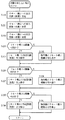
図12、図13は請求項1および請求項3に関する実施の形態の動作処理の手順を示したフローチャートである。
まず、操作機に対してプリントする総部数(枚数)の設定が行われる(ステップ200)。図15に代表される操作部画面にてプリント諸設定及び連結動作モードの設定を行い(ステップ201)、連結モードに設定すると(ステップ201;Y)、他の連結機への出力をするか否かを問う画面(図16)を操作部に出す(ステップ202)。ここで、連結動作モードにしない場合(ステップ201;N)および設定していても、他の連結器への出力をしない場合(ステップ202;N)には、操作機のみで設定された総部数(枚数)のプリントを行い(ステップ203)処理を終了する。
【0040】
一方、連結モードに入り、他機に出力する場合(ステップ202;Y)には、図17の画面に代表される設定モードにて、あらかじめユーザーが設定した「自動分担動作設定」に従い処理をし、連結機へのプリント配分を変更する。
請求項1に対応する実施の形態では前記「自動分担動作設定」を設定した場合であり(ステップ204;Y)、操作機、および連結機への出力部数(枚数)を図18に代表される設定画面にて設定する(ステップ205)。このときはじめに設定した総部数(枚数)に対して操作機、連結機の設定部数(枚数)の和が同じになるようにする。
【0041】
その後、各連結機の定着温度の問い合わせを行う(ステップ206)。連結機側では問い合わせに対しサーミスタから読み取った現在の定着制御温度を送信し、操作機側ではそれら情報を基に、どの連結機にプリントを割り当てれば一番速いかを判断し、設定部数(枚数)分の出力指示を出す。即ち、最もリロードに近い連結機に出力する(ステップ207)。ここで、リロードとは、定着温度が定着可能温度に到達しコピーが可能である状態をいう。
また、操作機、連結機共に分担のコピーが終了した時点で、操作機の操作部に図19のように出力先と部数(枚数)を表示させる(ステップ208)。
【0042】
請求項3に対応する実施の形態では、請求項1に対応する実施の形態と同様のフロー(図13)にて、操作機、連結機への出力部数(枚数)を設定する(ステップ215)。その後、各連結機のプリント待ち所要時間の問い合わせを行う(ステップ216)。請求項1に対応する実施の形態と同様に連結機側では問い合わせに対しサーミスタから読み取った現在の定着制御温度、エンジンのイニシャル動作、スキャナのイニシャル動作などから、「残りのプリント待ち所要時間」を算出し、送信する。操作機側ではそれら情報を基に、どの連結機にプリントを割り当てれば一番速いかを判断し、設定部数(枚数)分の出力指示を出す(ステップ217)。また、操作機、連結機共に分担のコピーが終了した時点で、操作機の操作部に図19のように出力先と部数(枚数)を表示させる(ステップ218)。
【0043】
また、請求項1および請求項3に対応する実施の形態で各連結機から得られる「定着温度」や「残りのプリント待ち所要時間」の情報を図20や図21のようにプリント中に操作機の表示部に表示させることにより、ユーザーはリアルタイムに各連結機のプリント待ち状態を把握することができ、システムの稼働性を高める上で有効な使い方ができる。
【0044】
図14は前記「自動分担動作設定」を設定しない場合の処理手順を示したフローチャートであり、(図13ステップ204;N)、ユーザーが出力したい連結機及び出力部数(枚数)を図22、図23に代表される設定画面にて任意に設定する(ステップ220〜222)。このとき始めに設定した総部数(枚数)に対して操作機、連結機の設定部数(枚数)の和が同じになるようにする。その後、操作機を含む出力設定をした連結機の稼働状態を番号の若い順番に見ていき(ステップ223、226、229)、稼働できる連結機に設定部数(枚数)分の出力指示を出し(ステップ224、227、230)、稼働できない場合は操作機に稼働不可を表示する(ステップ225、228、231)。SC、ジャムなどでコピーが行えない状態の連結機に対しては、操作機、連結機共に分担のコピーが終了した時点で、図24のように操作機の操作部にその状態を表示させる。
【0045】
【発明の効果】
請求項1記載の発明では、他の画像形成装置がリロード待ち状態の場合でも、定着温度がリロードに最も近いコピー機を選択手段で選択して出力されるため、ユーザーは操作待ちすることなく、システムとしての効率を上げることができる。
請求項2記載の発明によれば、定着温度を表示手段に表示させることにより、ユーザーが待ち時間を認識できるため、プリント出力の待ちの時間を有効に使うことができる。
【0046】
請求項3記載の発明によれば、他の画像形成装置がリロード待ち状態の場合でも、プリント待ち所要時間が最も短いコピー機を選定手段が自動選定してプリント出力されるため、ユーザーは操作待ちすることなく、システムとしての効率を上げることができる。
請求項4記載の発明によれば、接続機のプリント待ち所要時間を表示する所要時間表示手段に表示させることにより、ユーザーが待ち時間を認識できるため、プリント出力の待ちの時間を有効に使うことができ、システムとしての効率を上げることができる。
【図面の簡単な説明】
【図1】本発明の実施の形態における画像形成装置を示した図である。
【図2】操作部を示した図である。
【図3】操作部の液晶タッチパネルの表示例を示した図である。
【図4】本実施の形態のハード構成例である。
【図5】ネットワークコピーのシステム例を示した図である。
【図6】SCSIを用いた場合の本実施の形態のハード構成例である。
【図7】ソフトウェアの概念図である。
【図8】本実施の形態における画像処理部の構成例を示す図である。
【図9】画像メモリコントローラと画像メモリの詳細を説明する図である。
【図10】セレクタにおける画像信号について説明する図である。
【図11】電子ソートの動作例である。
【図12】請求項1に対応する動作処理手順のフローチャートである。
【図13】請求項3に対応する動作処理手順のフローチャートである。
【図14】自動分担動作設定をしない場合のフローチャートである。
【図15】操作部画面の表示例である。
【図16】他の連結機への出力を問う操作部画面の表示例である。
【図17】多機に出力する場合の操作部画面の表示例である。
【図18】出力部数の設定画面の表示例である。
【図19】出力先と部数の表示例である。
【図20】操作機の表示例である。
【図21】操作機の表示例である。
【図22】操作機の設定画面の例である。
【図23】操作機の設定画面の例である。
【図24】操作機の画面表示の例である。
【符号の説明】
30 操作部
31 液晶タッチパネル
32 テンキー
33 クリア/ストップキー
34 プリントキー
35 モードクリアキー
37 機能キー
50 読み取りユニット
51 露光ランプ
52 第1ミラー
53 レンズ
54 CCDイメージセンサ
55 第2ミラー
56 第3ミラー
57 書き込みユニット
58 レーザ出力ユニット
59 結像レンズ
60 ミラー
61 A/Dコンバータ
62 シェーディング補正
63 画像処理部
64 セレクタ
65 画像メモリコントローラ
66 画像メモリ
68 CPU
69 ROM
70 RAM
80 SCSIドライバ
100 後処理装置のフィニシャ
101 入力データセレクタ
102 画像合成
103 1次圧縮/伸長
104 出力データセレクタ
105 2次圧縮/伸長
106 1次記憶装置
107 2次記憶装置
120 後処理装置のフィニシャ
121 分岐偏光板
122 通常排紙ローラ
123 搬送ローラ
124 通常排紙トレイ
125、127 搬送ローラ
128 ステープル台
129 ジョガー
130 ステープル完了排紙トレイ
131 両面給紙ユニット
132 分岐爪[0001]
BACKGROUND OF THE INVENTION
The present invention relates to the output of a plurality of connected image forming apparatuses such as digital copying machines.
[0002]
[Prior art]
Conventionally, for various purposes, a plurality of image signal output means such as an image scanner, a word processor, and a personal computer that output image signals, and an image forming apparatus such as a plurality of printers that perform image formation using each of these image signals, A system combining the above has been proposed.
For example, as seen in the invention described in Japanese Patent Laid-Open No. 5-304575, a system has been proposed in which a digital copying machine is connected to increase the speed of copying operation and to make a large amount of copies in a short time.
[0003]
[Problems to be solved by the invention]
However, in the above invention, since the same operation is performed by a plurality of copying machines, there is a problem that the processing time varies depending on the state of the copying machine.
Accordingly, a first object of the present invention is to reduce the copy time and improve the productivity by using linked copying. In a digital copier network system, even if the copier is in a print waiting state for various reasons, the user can It is an object of the present invention to provide an image forming apparatus that does not wait for operation.
The second object of the present invention is to enable the user to know which copier starts up most quickly when the user recognizes the fixing temperature in a copier that can be operated on a linked system, so that the operation can be efficiently performed. An image forming apparatus capable of performing the above is provided.
A third object of the present invention is to efficiently recognize which copy machine is started up most quickly by recognizing the time required for printing in a copy machine that can be operated on a linked system. An object of the present invention is to provide an image forming apparatus that can be operated.
[0004]
[Means for Solving the Problems]
According to the first aspect of the present invention, image reading means for reading image data of a document, storage means for storing image data read by the image reading means, and image data stored in the storage means are printed on transfer paper. An output unit, a connection unit that connects to another image forming apparatus, and transmits and receives image data and various commands, and another image forming apparatus that receives image data read by the image reading unit via the connection unit When printing is performed in a shared manner, the detection means that detects whether or not the connected machine is waiting for reloading and the result of detection by this detecting means that when the connected machine is waiting for reloading, the fixing temperature is the highest reload temperature. A selection means for selecting a connection device close to A connection unit selected by the selection unit and the output unit, a display unit for displaying the number of sheets output by each; With the above, the first object is achieved.
[0005]
In the invention of
[0006]
According to the third aspect of the present invention, the image reading means for reading the image data of the document, the storage means for storing the image data read by the image reading means, and the image data stored in the storage means are printed on the transfer paper. An output unit, a connection unit that connects to another image forming apparatus, and transmits and receives image data and various commands, and another image forming apparatus that receives image data read by the image reading unit via the connection unit When printing is performed in a shared manner, the detection means for detecting whether or not the connected machine is in a reload wait state, and when the connected machine is in a reload wait state as a result of detection by this detection means, the fixing temperature and initial A selection means for determining the print waiting time from the operation time and selecting the connection machine with the shortest time, A connection unit selected by the selection unit and the output unit, a display unit for displaying the number of sheets output by each; With the above, the first object is achieved.
[0007]
In the invention according to
[0008]
DETAILED DESCRIPTION OF THE INVENTION
Hereinafter, a preferred embodiment of the present invention will be described in detail with reference to FIGS.
FIG. 1 is a diagram showing an image forming apparatus according to an embodiment of the present invention.
A document bundle placed on the document table 2 in the ADF (automatic document feeder) 1 with the image surface of the document facing up is pressed when the
[0009]
The transfer papers stacked on the
[0010]
The finisher 120 of the post-processing apparatus can guide the transfer paper conveyed by the paper discharge roller of the main body in the direction of the normal paper discharge roller 123 and the direction of the staple processing unit. By switching the branched polarizing plate 121 upward, the sheet can be discharged to the normal discharge tray 124 side via the transport roller 122. Further, by switching the branching polarizing plate 121 downward, it can be conveyed to the staple table 128 via the
The transfer paper loaded on the staple table 128 is aligned by the paper jogger 129 every time one sheet is discharged, and is bound by the stapler 126 upon completion of partial copying. The transfer paper group bound by the stapler 126 is stored in the staple completion paper discharge tray 130 by its own weight.
[0011]
On the other hand, the normal paper discharge tray 124 is a paper discharge tray that can move back and forth. A paper discharge tray 124 that can be moved back and forth is moved back and forth for each document or each copy unit sorted by the image memory, and sorts the copy paper that is simply discharged.
When images are formed on both sides of the transfer paper, the transfer paper fed from each of the
[0012]
Thereafter, the transfer paper stocked in the double-sided paper feed unit 131 is re-fed from the double-sided paper feed unit 131 to transfer the toner image formed on the photosensitive member 15 again, and the branching claw 132 for switching the path. Is set on the lower side and guided to the paper discharge tray 124. In this way, the duplex feeding unit 131 is used when images are created on both sides of the transfer sheet.
[0013]
FIG. 2 is a diagram showing the
The
[0014]
FIG. 3 is a diagram illustrating a display example of the liquid
When the operator touches a key displayed on the liquid
In FIG. 3, the upper left is a message area that displays messages such as "Ready to copy" and "Please wait", the right is the copy number display area that displays the set number of copies, and the automatic adjustment that automatically adjusts the image density below it. Specify the density key, the automatic paper selection key to automatically select the transfer paper, the same magnification key to set the magnification to the same magnification, the sort key to specify the processing to arrange the copies part by page, and the processing to sort the copies by page A stack key, a staple key for specifying a process for binding sorted items one by one, a scaling key for setting an enlargement / reduction ratio, a duplex key for setting a duplex mode, an erase / move key for setting a binding margin mode, This is a connection mode key for printing out a large number of printing operations divided into a plurality of pieces through a network of a digital copying machine.
The selected mode is shaded.
[0015]
With reference to FIG. 1, description will be given of the image reading means in this embodiment and the operation until the latent image is formed on the recording surface. A latent image is a potential distribution generated by converting an image into light information and irradiating it on the surface of the photoreceptor.
The reading unit 50 includes a contact glass 6 on which an original is placed and an optical scanning system. The optical scanning system includes an exposure lamp 51, a
[0016]
The document image is read by the
The
The laser light emitted from the
[0017]
The polarized laser light is exposed and scanned in the direction (main scanning direction) perpendicular to the direction in which the photosensitive member 15 rotates, and the image signal output from the selector 64 of the image processing unit to be described later is recorded line by line. An image (electrostatic latent image) is formed on the surface of the photosensitive member by repeating main scanning at a predetermined cycle corresponding to the rotational speed and recording density of the photosensitive member 15.
As described above, the laser beam output from the
[0018]
The configuration of the image processing unit (image reading unit and image writing unit) in the present embodiment will be described with reference to FIG.
The light emitted from the exposure lamp 51 illuminates the original surface, and the reflected light from the original surface is imaged and received by a
The selector 64 switches the destination of the image signal to the scaling unit 71 or the image memory controller 65. The image signal that has passed through the scaling unit 71 is enlarged / reduced in accordance with the scaling ratio and sent to the
[0019]
Although not explicitly shown in FIG. 8, in addition to image data input from the reading unit 50, image data supplied from outside (for example, output from a data processing device such as a personal computer) is output to the IPU (image processing unit). A function of selecting input / output of a plurality of data.
A CPU (Central Processing Unit) 68 for setting the memory controller 65 and the like and controlling the reading unit 50 and the
[0020]
Here, an image signal for one page in the selector 64 will be described with reference to FIG.
/ FGATE represents a valid period in the sub-scanning direction of one page of image data. / LSYNC is a main scanning synchronization signal for each line, and the image signal becomes valid at a predetermined clock after this signal rises. A signal indicating that the image signal in the main scanning direction is valid is / LGATE. These signals are synchronized with the pixel clock VCLK, and one pixel of data is sent for one cycle of VCLK. The IPU 49 has separate generation mechanisms for / FGATE, / LSYNC, / LGATE, and VCLK for each of image input and output, and various image input / output combinations can be realized.
[0021]
Next, details of the memory controller 65 and the image memory 66 in FIG. 8 will be described with reference to FIG.
The memory controller 65 has blocks of an
[0022]
The image memory 66 includes a
[0023]
The
By adopting the configuration of the image memory as described above, it is possible to realize an image forming apparatus capable of processing such as input / output, storage, and processing of a large amount of image data with a low cost and a relatively simple configuration. Become.
[0024]
Next, an outline of the operation of the memory controller 65 will be described.
1. Image input (save to image memory)
The
The image data selected by the
The image data processed by the
The data written in the
[0025]
2. Image output (read from image memory)
When outputting an image, the image data stored in the
The
When the output target image is not stored in the
[0026]
Further, in order to share the work, it is necessary to exchange commands and image data with other digital copying machines, which is realized by using a SCSI interface in this embodiment. The memory controller 65 in FIG. 8 implements this via the
Here, the operation reservation described in this example means that the copying operation cannot be started when the copying machine is in the process of heating the fixing, but the fixing heating is ended by completing the mode setting and setting of the original and making a reservation. This is a function that automatically starts the copy operation when the copy operation becomes possible. In this embodiment, the operation reservation is possible during the fixing heating, but other things that can be operated over time are also eligible. It is conceivable that the LCT tray rise time, polygon motor rotation stabilization time, toner replenishment operation, etc.
[0027]
In the hardware configuration diagram of FIG. 4, the system includes an image reading unit, an image writing unit, a system controller, a memory unit, a user restriction device, a human body detection sensor, a CSS (remote diagnosis device), and a clock. Required only when implementing the memory function. In addition, human body detection is necessary only when realizing the function of automatically canceling the preheating mode when the user approaches the machine in the preheating mode, and CSS is a remote judgment, that is, a machine error occurs. In such a case, it is a function that automatically notifies the service center and monitors the execution / use state of the machine from a remote location, so it should be installed only when such a function is necessary.
[0028]
The DRAM block in the memory unit in FIG. 4 is for storing the image signal read from the image reading unit, and transfers the image data stored in the image writing unit in response to a request from the system controller. Can do. In addition, the compression block has a compression function such as MH, MR, or MMR, and can compress the image once read to improve the use efficiency of the memory (DRAM). Further, the rotation of the image is realized by changing the address read from the image writing unit and its direction.
[0029]
In “Hardware Configuration Example 1” in FIG. 4, the image reading unit, the image writing unit, the memory unit, and the CSS are controlled by only one CPU of the system controller.
On the other hand, in “Hardware Configuration-2” in FIG. 4, the image reading unit, the image writing unit, and the memory unit are each provided with a CPU, and commands from the system controller to each controller are transmitted via control signal lines. The system hardware configuration can be freely configured.
[0030]
FIG. 5 is a diagram showing an example of a network copy system according to the present embodiment.
In FIG. 5, eight digital copies are networked, but the number of connected copies need not be limited.
Next, a hardware configuration example for realizing the present invention will be described with reference to FIG. As shown in FIG. 6, the hardware configuration of one digital PPC is almost the same as that shown in “Hardware configuration example 1” in FIG. 4, but the read image is stored in the memory unit. In order to transfer to an external network or store image data from the network in a DRAM block in the memory unit, a SCSI and a SCSI controller are used as network means.
As the network means, for example, various means such as using Ethernet as a physical means and using TCP / IP communication of an OSI (Open System Interface) reference model for data communication are possible.
[0031]
Further, by using the configuration as shown in FIG. 6, not only the transfer of image data as described above, but also the control command and setting such as the in-machine status notification of each machine existing on the network and the remote output command described later. The command is also transferred.
Next, an operation (hereinafter referred to as remote output) of transferring an image read by “digital PPC-1” to an image writing unit of “digital PPC-2” will be described with reference to FIGS.
FIG. 7 is a conceptual diagram of software. The “copy application” shown in FIG. 7 is an application that executes a copy sequence for executing a copying operation, “input / output control” is a layer (device driver) that logically / physically converts data, and the operation unit controller is an MMI. (Man-machine interface) (layer that performs LCD display, LED on / off, key input scan, etc. at logical level), and “peripheral controller” is a PPC such as an automatic duplex unit, sorter, ADF, etc. This is a layer that performs control of peripheral devices attached to the PC at a logical level. The “image forming apparatus controller”, “image reading apparatus controller”, and “memory unit” are as described above.
[0032]
Also, the “daemon process” serves to read out image data stored in the memory unit and transfer the image data to the “image forming apparatus” when a print request is requested from another machine on the network. Exists as an application. Before the “daemon process” reads the image from the memory unit and performs the print operation, the image transfer from other machines on the network must be finished.
[0033]
Here, the operation unit, the peripheral device, the image forming apparatus, the image reading apparatus, and the memory unit are treated as resources (resources) held by each PPC. When “Digital PPC-1” in FIG. 7 executes a copying operation using its own resources (when the print start key is pressed), “Image forming apparatus” “Image reading” with respect to “System controller”. Requests each resource of “device” or “peripheral device” and “memory unit” to the “system control” unit as necessary. In response to a request from the “copy application”, the “system control” unit arbitrates resource usage rights and notifies the “copy application” of the mediation result (usability). When “Digital PPC-1” is used stand-alone (not connected to the network), all the resources held by the system are in a state where the “copy application” can be occupied, and the copying operation is immediately executed.
[0034]
On the other hand, the right to use resources for a “system controller” of a remote digital PPC that executes a print operation using resources of another machine (hereinafter referred to as a remote digital PPC) existing on the network as in the present embodiment. Request.
The system controller of the remote digital PPC performs resource arbitration according to the request, and notifies the requesting machine application of the result.
When the usage right is permitted, the application reads the image, and when the image storage into the memory unit of the application is completed, the application of the remote output destination machine is connected via the external interface (in this embodiment, SCSI). Transfer images to the memory unit. When the image transfer is complete, send the various conditions (printing port, paper discharge port, number of prints, etc.) to execute printing to the “daemon process” of the remote output destination machine, and then execute the “print start” command. Send.
[0035]
When the “daemon process” at the remote output destination receives the “print start” command, it requests the “system controller” of itself (machine executing the remote output) to start printing, and the remote output is executed by the system controller. .
[0036]
When the “digital PPC-2” memory unit is used by the “digital PPC-1”, the “digital PPC-2” memory unit is “digital PPC-2” (or as shown in FIG. 5). When a plurality of digital PPCs are connected to the network, the use of an application other than “Digital PPC-1” is disabled.
[0037]
FIG. 11 shows an outline of the operation in the electronic sort mode (a function for sorting the images in the memory) during the connection operation.
FIG. 11 shows a case where three copies of a document are sorted and a six-copy operation is performed by the operating device and another machine.
The original is operated by sharing the copy operation between the operation device (master device) and one slave device.
On the operating device side, the document reading operation and the printing operation on the master device side are usually operated simultaneously. In actual operation, the scanner image is printed as it is and the image is written in the memory in parallel. After the first copy printing operation is completed, an image is read from the memory for the second copy and printed.
[0038]
On the other hand, the slave unit stores the image sent from the controller in the memory. Whether the images can be printed in parallel depends on the performance of the memory unit. Here, the print operation is executed after the memory storage operation is completed. After the first copy is printed, the second and third copies are processed.
Also, here, the specified number of copies is printed in half, but this allocation can be freely set by the user, and even if one of the machines is interrupted, it is easy to change the number of copies per copy. is there. The remaining number of remaining suspensions can be allocated.
[0039]
Next, the present embodiment will be described with reference to FIGS.
FIG. 12 and FIG. 13 are flowcharts showing the procedure of the operation processing according to the first and third embodiments.
First, the total number of copies (number of sheets) to be printed is set for the controller (step 200). 15 are set on the operation unit screen represented by FIG. 15 (step 201). When the connection mode is set (
[0040]
On the other hand, when entering the connection mode and outputting to another machine (
In the embodiment corresponding to claim 1, the “automatic sharing operation setting” is set (step 204; Y), and the number of copies (number of copies) to the operating device and the coupling device is represented by FIG. Setting is made on the setting screen (step 205). At this time, the sum of the set number of copies (the number of copies) of the operating device and the coupling device is set to be the same as the total number of copies (the number of copies) initially set.
[0041]
Thereafter, an inquiry is made about the fixing temperature of each coupling machine (step 206). The connected machine sends the current fixing control temperature read from the thermistor in response to the inquiry, and on the operating machine side, based on this information, determines which connected machine is assigned the fastest print, and sets the number of copies ( Output instructions for (number of sheets). That is, it outputs to the coupling machine closest to reloading (step 207). Here, reloading refers to a state where the fixing temperature reaches the fixable temperature and copying is possible.
Further, at the time when the sharing of both the operating device and the connecting device is completed, the output destination and the number of copies (number of copies) are displayed on the operating unit of the operating device as shown in FIG. 19 (step 208).
[0042]
In the embodiment corresponding to claim 3, the number of copies (number of copies) to the operating device and the coupling device is set in the same flow (FIG. 13) as the embodiment corresponding to claim 1 (step 215). . Thereafter, an inquiry is made about the time required for printing of each coupling machine (step 216). In the same manner as in the embodiment corresponding to claim 1, the “remaining print waiting time” is calculated from the current fixing control temperature read from the thermistor, the initial operation of the engine, the initial operation of the scanner, etc. Calculate and send. On the operating device side, based on such information, it is determined to which connecting device the print is assigned the fastest, and an output instruction for the set number of copies (number of copies) is issued (step 217). Further, when the sharing of both the operating device and the connecting device is completed, the output destination and the number of copies (number of copies) are displayed on the operating unit of the operating device as shown in FIG. 19 (step 218).
[0043]
In addition, information on “fixing temperature” and “remaining print waiting time” obtained from each coupling machine in the embodiment corresponding to
[0044]
FIG. 14 is a flowchart showing the processing procedure when the “automatic sharing operation setting” is not set (step 204 in FIG. 13; N), and the coupling machine and the number of copies (number of copies) that the user wants to output are shown in FIG. An arbitrary setting is made on a setting screen represented by 23 (
[0045]
【The invention's effect】
According to the first aspect of the present invention, even when the other image forming apparatus is in the reloading waiting state, the copying machine having the fixing temperature that is closest to the reloading is selected and output by the selection means, so that the user does not wait for the operation. System efficiency can be increased.
According to the second aspect of the present invention, since the user can recognize the waiting time by displaying the fixing temperature on the display means, the waiting time for the print output can be used effectively.
[0046]
According to the third aspect of the present invention, even when the other image forming apparatus is in the reloading waiting state, the copy unit having the shortest waiting time for printing is automatically selected and printed out by the selection means. Without increasing the efficiency of the system.
According to the fourth aspect of the present invention, since the user can recognize the waiting time by displaying it on the required time display means for displaying the required time for printing of the connection device, the waiting time for the print output can be used effectively. Can improve the efficiency of the system.
[Brief description of the drawings]
FIG. 1 is a diagram illustrating an image forming apparatus according to an embodiment of the present invention.
FIG. 2 is a diagram illustrating an operation unit.
FIG. 3 is a diagram illustrating a display example of a liquid crystal touch panel of an operation unit.
FIG. 4 is a hardware configuration example of the present embodiment.
FIG. 5 is a diagram illustrating an example of a network copy system.
FIG. 6 is a hardware configuration example of the present embodiment when SCSI is used.
FIG. 7 is a conceptual diagram of software.
FIG. 8 is a diagram illustrating a configuration example of an image processing unit in the present embodiment.
FIG. 9 is a diagram illustrating details of an image memory controller and an image memory.
FIG. 10 is a diagram illustrating an image signal in a selector.
FIG. 11 is an operation example of electronic sorting.
FIG. 12 is a flowchart of an operation processing procedure corresponding to claim 1;
FIG. 13 is a flowchart of an operation processing procedure corresponding to claim 3;
FIG. 14 is a flowchart when automatic sharing operation setting is not performed.
FIG. 15 is a display example of an operation unit screen.
FIG. 16 is a display example of an operation unit screen asking for output to another coupling machine.
FIG. 17 is a display example of an operation unit screen when outputting to a multi-function device.
FIG. 18 is a display example of an output number setting screen.
FIG. 19 is a display example of an output destination and the number of copies.
FIG. 20 is a display example of an operating device.
FIG. 21 is a display example of an operating device.
FIG. 22 is an example of a setting screen of an operating device.
FIG. 23 is an example of a setting screen of an operating device.
FIG. 24 is an example of a screen display of the operating device.
[Explanation of symbols]
30 Operation unit
31 LCD touch panel
32 numeric keypad
33 Clear / Stop key
34 Print key
35 Mode clear key
37 Function keys
50 reading unit
51 Exposure lamp
52 First mirror
53 lenses
54 CCD image sensor
55 Second mirror
56 Third mirror
57 Writing unit
58 Laser output unit
59 Imaging lens
60 mirror
61 A / D converter
62 Shading correction
63 Image processing unit
64 selector
65 Image memory controller
66 Image memory
68 CPU
69 ROM
70 RAM
80 SCSI driver
100 Finisher finisher
101 Input data selector
102 Image composition
103 Primary compression / decompression
104 Output data selector
105 Secondary compression / decompression
106 Primary storage device
107 Secondary storage device
120 Finisher of finisher
121 Branched Polarizing Plate
122 Normal paper discharge roller
123 Transport roller
124 Normal output tray
125, 127 transport rollers
128 Staple stand
129 Jogger
130 Staple completion output tray
131 Double-sided paper feed unit
132 Branch Claw
Claims (4)
この画像読取手段で読み取った画像データを記憶する記憶手段と、
この記憶手段に記憶された画像データを転写紙に印字する出力手段と、
他の画像形成装置と接続して、画像データおよび各種コマンドの送受信を行う接続手段と、
前記画像読取手段で読み取った画像データを、前記接続手段を介して、他の画像形成装置で分担して印字出力させる場合、接続機がリロード待ち状態であるか否かを検知する検知手段と、
この検知手段による検知の結果、接続機がリロード待ち状態だったとき、定着温度が最もリロード温度に近い接続機を選択する選択手段と、
この選択手段により選択された接続機と前記出力手段、各々で出力された枚数を表示する表示手段と、
を備えたことを特徴とする画像形成装置。Image reading means for reading image data of a document;
Storage means for storing image data read by the image reading means;
Output means for printing image data stored in the storage means on transfer paper;
Connecting means for connecting to another image forming apparatus and transmitting and receiving image data and various commands;
When the image data read by the image reading unit is shared by another image forming apparatus via the connecting unit and printed out, the detecting unit detects whether or not the connecting machine is in a reload waiting state;
As a result of detection by this detection means, when the connected machine is in a reload waiting state, a selection means for selecting a connected machine whose fixing temperature is closest to the reload temperature;
A connection unit selected by the selection unit and the output unit, a display unit for displaying the number of sheets output by each;
An image forming apparatus comprising:
この画像読取手段で読み取った画像データを記憶する記憶手段と、
この記憶手段に記憶された画像データを転写紙に印字する出力手段と、
他の画像形成装置と接続して、画像データおよび各種コマンドの送受信を行う接続手段と、
前記画像読取手段で読み取った画像データを、前記接続手段を介して、他の画像形成装置で分担して印字出力させる場合、接続機がリロード待ち状態であるか否かを検知する検知手段と、
この検知手段による検知の結果、接続機がリロード待ち状態であったとき、定着温度とイニシャル動作時間からプリント待ち所要時間を割り出し、もっとも所要時間の少ない接続機を選定する選定手段と、
この選定手段により選択された接続機と前記出力手段、各々で出力された枚数を表示する表示手段と、
を備えたことを特徴とする画像形成装置。Image reading means for reading image data of a document;
Storage means for storing image data read by the image reading means;
Output means for printing image data stored in the storage means on transfer paper;
Connecting means for connecting to another image forming apparatus and transmitting and receiving image data and various commands;
When the image data read by the image reading unit is shared by another image forming apparatus via the connecting unit and printed out, the detecting unit detects whether or not the connecting machine is in a reload waiting state;
As a result of detection by this detection means, when the connected machine is in a reloading waiting state, a selection means for calculating the required print wait time from the fixing temperature and the initial operation time and selecting the connected machine with the shortest required time;
A connection unit selected by the selection unit and the output unit, a display unit for displaying the number of sheets output by each;
An image forming apparatus comprising:
Priority Applications (1)
| Application Number | Priority Date | Filing Date | Title |
|---|---|---|---|
| JP11592098A JP3614657B2 (en) | 1998-04-09 | 1998-04-09 | Image forming apparatus |
Applications Claiming Priority (1)
| Application Number | Priority Date | Filing Date | Title |
|---|---|---|---|
| JP11592098A JP3614657B2 (en) | 1998-04-09 | 1998-04-09 | Image forming apparatus |
Publications (2)
| Publication Number | Publication Date |
|---|---|
| JPH11298663A JPH11298663A (en) | 1999-10-29 |
| JP3614657B2 true JP3614657B2 (en) | 2005-01-26 |
Family
ID=14674488
Family Applications (1)
| Application Number | Title | Priority Date | Filing Date |
|---|---|---|---|
| JP11592098A Expired - Fee Related JP3614657B2 (en) | 1998-04-09 | 1998-04-09 | Image forming apparatus |
Country Status (1)
| Country | Link |
|---|---|
| JP (1) | JP3614657B2 (en) |
Family Cites Families (7)
| Publication number | Priority date | Publication date | Assignee | Title |
|---|---|---|---|---|
| JPH05304575A (en) * | 1992-04-24 | 1993-11-16 | Sanyo Electric Co Ltd | Digital copying machine |
| JP3660363B2 (en) * | 1992-05-28 | 2005-06-15 | 株式会社リコー | Image forming apparatus management system and image forming apparatus |
| JP3319819B2 (en) * | 1993-06-25 | 2002-09-03 | 株式会社リコー | Image forming device management system |
| JPH07261955A (en) * | 1994-03-18 | 1995-10-13 | Mita Ind Co Ltd | Image forming network device |
| JPH0897959A (en) * | 1994-09-22 | 1996-04-12 | Ricoh Co Ltd | Network system for digital copying machine |
| JP3673542B2 (en) * | 1994-12-26 | 2005-07-20 | キヤノン株式会社 | Image forming apparatus and system |
| JPH08331292A (en) * | 1995-06-05 | 1996-12-13 | Konica Corp | Copy machine |
-
1998
- 1998-04-09 JP JP11592098A patent/JP3614657B2/en not_active Expired - Fee Related
Also Published As
| Publication number | Publication date |
|---|---|
| JPH11298663A (en) | 1999-10-29 |
Similar Documents
| Publication | Publication Date | Title |
|---|---|---|
| JP3895488B2 (en) | Digital copier network system | |
| JP4090607B2 (en) | Concatenated image forming apparatus | |
| JP3785274B2 (en) | Copier copying method for copying machine network system | |
| JP3869977B2 (en) | Image forming apparatus and image forming apparatus system | |
| JP3858192B2 (en) | Image forming system and image forming method | |
| JP3614657B2 (en) | Image forming apparatus | |
| JP2000347826A (en) | Image forming device network and its connecting operation method | |
| JP2000261595A (en) | Image forming system | |
| JP3538325B2 (en) | Network system for image forming device | |
| JP3550494B2 (en) | Image forming device | |
| JP2000335057A (en) | Image forming system and method therefor | |
| JP3621561B2 (en) | Image forming apparatus | |
| JPH1188570A (en) | Image forming system | |
| JP4136197B2 (en) | Image forming apparatus | |
| JPH11289436A (en) | Image forming device | |
| JPH11231730A (en) | Image forming device | |
| JP3716085B2 (en) | Image forming apparatus | |
| JP3645110B2 (en) | Copier network system and master image forming apparatus | |
| JPH10322533A (en) | Copying machine and copying machine network system | |
| JPH10153928A (en) | Network system for copying machine | |
| JP2000276310A (en) | Image forming system | |
| JP2004185039A (en) | Image forming apparatus | |
| JPH11308424A (en) | Image formation device | |
| JP2001268284A (en) | Connected image-forming system | |
| JPH11127290A (en) | Network system of image forming device |
Legal Events
| Date | Code | Title | Description |
|---|---|---|---|
| A977 | Report on retrieval |
Free format text: JAPANESE INTERMEDIATE CODE: A971007 Effective date: 20040225 |
|
| A131 | Notification of reasons for refusal |
Free format text: JAPANESE INTERMEDIATE CODE: A131 Effective date: 20040728 |
|
| A521 | Written amendment |
Free format text: JAPANESE INTERMEDIATE CODE: A523 Effective date: 20040927 |
|
| TRDD | Decision of grant or rejection written | ||
| A01 | Written decision to grant a patent or to grant a registration (utility model) |
Free format text: JAPANESE INTERMEDIATE CODE: A01 Effective date: 20041022 |
|
| A61 | First payment of annual fees (during grant procedure) |
Free format text: JAPANESE INTERMEDIATE CODE: A61 Effective date: 20041027 |
|
| R150 | Certificate of patent or registration of utility model |
Free format text: JAPANESE INTERMEDIATE CODE: R150 |
|
| FPAY | Renewal fee payment (event date is renewal date of database) |
Free format text: PAYMENT UNTIL: 20071112 Year of fee payment: 3 |
|
| FPAY | Renewal fee payment (event date is renewal date of database) |
Free format text: PAYMENT UNTIL: 20081112 Year of fee payment: 4 |
|
| FPAY | Renewal fee payment (event date is renewal date of database) |
Free format text: PAYMENT UNTIL: 20081112 Year of fee payment: 4 |
|
| FPAY | Renewal fee payment (event date is renewal date of database) |
Free format text: PAYMENT UNTIL: 20091112 Year of fee payment: 5 |
|
| FPAY | Renewal fee payment (event date is renewal date of database) |
Free format text: PAYMENT UNTIL: 20101112 Year of fee payment: 6 |
|
| LAPS | Cancellation because of no payment of annual fees |