JP3607029B2 - Rolling mill control method and control apparatus - Google Patents
Rolling mill control method and control apparatus Download PDFInfo
- Publication number
- JP3607029B2 JP3607029B2 JP00578897A JP578897A JP3607029B2 JP 3607029 B2 JP3607029 B2 JP 3607029B2 JP 00578897 A JP00578897 A JP 00578897A JP 578897 A JP578897 A JP 578897A JP 3607029 B2 JP3607029 B2 JP 3607029B2
- Authority
- JP
- Japan
- Prior art keywords
- rolling
- crown
- rolled
- rolling mill
- value
- Prior art date
- Legal status (The legal status is an assumption and is not a legal conclusion. Google has not performed a legal analysis and makes no representation as to the accuracy of the status listed.)
- Expired - Lifetime
Links
- 238000005096 rolling process Methods 0.000 title claims description 260
- 238000000034 method Methods 0.000 title claims description 12
- 239000000463 material Substances 0.000 claims description 209
- 238000012937 correction Methods 0.000 claims description 82
- 238000005452 bending Methods 0.000 claims description 13
- 230000002068 genetic effect Effects 0.000 claims description 9
- 238000013000 roll bending Methods 0.000 description 10
- 238000010586 diagram Methods 0.000 description 5
- XEEYBQQBJWHFJM-UHFFFAOYSA-N Iron Chemical compound [Fe] XEEYBQQBJWHFJM-UHFFFAOYSA-N 0.000 description 2
- 229910000831 Steel Inorganic materials 0.000 description 2
- 238000013459 approach Methods 0.000 description 2
- 238000005516 engineering process Methods 0.000 description 2
- 230000002093 peripheral effect Effects 0.000 description 2
- 239000010959 steel Substances 0.000 description 2
- 238000012360 testing method Methods 0.000 description 2
- 238000011144 upstream manufacturing Methods 0.000 description 2
- 238000001816 cooling Methods 0.000 description 1
- 238000001514 detection method Methods 0.000 description 1
- 238000011161 development Methods 0.000 description 1
- 230000000694 effects Effects 0.000 description 1
- 229910052742 iron Inorganic materials 0.000 description 1
- 238000005259 measurement Methods 0.000 description 1
- QVRVXSZKCXFBTE-UHFFFAOYSA-N n-[4-(6,7-dimethoxy-3,4-dihydro-1h-isoquinolin-2-yl)butyl]-2-(2-fluoroethoxy)-5-methylbenzamide Chemical compound C1C=2C=C(OC)C(OC)=CC=2CCN1CCCCNC(=O)C1=CC(C)=CC=C1OCCF QVRVXSZKCXFBTE-UHFFFAOYSA-N 0.000 description 1
- 239000002436 steel type Substances 0.000 description 1
- 238000003466 welding Methods 0.000 description 1
Images
Classifications
-
- B—PERFORMING OPERATIONS; TRANSPORTING
- B21—MECHANICAL METAL-WORKING WITHOUT ESSENTIALLY REMOVING MATERIAL; PUNCHING METAL
- B21B—ROLLING OF METAL
- B21B37/00—Control devices or methods specially adapted for metal-rolling mills or the work produced thereby
-
- B—PERFORMING OPERATIONS; TRANSPORTING
- B21—MECHANICAL METAL-WORKING WITHOUT ESSENTIALLY REMOVING MATERIAL; PUNCHING METAL
- B21B—ROLLING OF METAL
- B21B37/00—Control devices or methods specially adapted for metal-rolling mills or the work produced thereby
- B21B37/28—Control of flatness or profile during rolling of strip, sheets or plates
-
- B—PERFORMING OPERATIONS; TRANSPORTING
- B21—MECHANICAL METAL-WORKING WITHOUT ESSENTIALLY REMOVING MATERIAL; PUNCHING METAL
- B21B—ROLLING OF METAL
- B21B13/00—Metal-rolling stands, i.e. an assembly composed of a stand frame, rolls, and accessories
- B21B13/02—Metal-rolling stands, i.e. an assembly composed of a stand frame, rolls, and accessories with axes of rolls arranged horizontally
- B21B13/023—Metal-rolling stands, i.e. an assembly composed of a stand frame, rolls, and accessories with axes of rolls arranged horizontally the axis of the rolls being other than perpendicular to the direction of movement of the product, e.g. cross-rolling
-
- B—PERFORMING OPERATIONS; TRANSPORTING
- B21—MECHANICAL METAL-WORKING WITHOUT ESSENTIALLY REMOVING MATERIAL; PUNCHING METAL
- B21B—ROLLING OF METAL
- B21B31/00—Rolling stand structures; Mounting, adjusting, or interchanging rolls, roll mountings, or stand frames
- B21B31/16—Adjusting or positioning rolls
- B21B31/18—Adjusting or positioning rolls by moving rolls axially
- B21B31/185—Adjusting or positioning rolls by moving rolls axially and by crossing rolls
-
- B—PERFORMING OPERATIONS; TRANSPORTING
- B21—MECHANICAL METAL-WORKING WITHOUT ESSENTIALLY REMOVING MATERIAL; PUNCHING METAL
- B21B—ROLLING OF METAL
- B21B37/00—Control devices or methods specially adapted for metal-rolling mills or the work produced thereby
- B21B37/28—Control of flatness or profile during rolling of strip, sheets or plates
- B21B37/42—Control of flatness or profile during rolling of strip, sheets or plates using a combination of roll bending and axial shifting of the rolls
Landscapes
- Engineering & Computer Science (AREA)
- Mechanical Engineering (AREA)
- Control Of Metal Rolling (AREA)
Description
【0001】
【発明の属する技術分野】
本発明は、タンデムに配置された連続圧延機に好適な圧延機の制御に係り、特に、所望の板クラウン及び板平坦度の板を得る圧延機の制御方法及び制御装置に関する。
【0002】
【従来の技術】
この種の従来技術として、例えば、(社)日本鉄鋼協会圧延理論部会誌第100 回シンポジウム「圧延技術・圧延理論の発展と将来への潮流」(平成6年6月)第79頁乃至第90頁に「ホットストリップミルにおける高精度圧延技術」(西山泰行、芝尾信二、島津智他著)と題して、目標板クラウン及び目標板形状を達成しようとする制御システムが記載されている。この制御システムは、初期設定機能として、目標板クラウン及び目標板形状を達成する各スタンドのロールクロス角及びロールベンディング力の初期設定値を求める機能を有している。
【0003】
【発明が解決しようとする課題】
上述した制御システムは、板幅方向の板厚精度の向上に当り、クラウン比率遺伝係数や形状係数を用いているが、これらの係数を実際に求めることは困難を伴うものであった。
また、上述した制御システムは、圧延機により順に圧延される被圧延材のうち、時間的に先に圧延される先行材の圧延結果を、時間的に後に圧延される後行材の圧延に利用する点についての記載がなく、先行材と後行材とで圧延条件が異なる場合の記載がなかった。
【0004】
本発明は上記の課題を解決するためになされたもので、クラウン比率遺伝係数や形状変化係数を使用せずに済み、かつ、先行材の圧延結果を後行材の圧延制御に有効に利用することによって、後続の被圧延材の板クラウンと板平坦度を高精度に目標値に仕上げることのできる圧延機の制御方法及び制御装置を提供することを目的とする。
【0005】
【課題を解決するための手段】
上記目的を達成するための第1の発明は、タンデムに配置され、それぞれ板クラウンを制御するためのアクチュエータを有する複数の圧延機を制御するに当り、
外部から与えられた圧延情報に基づいて、被圧延材の圧延前に、圧延荷重、板幅及び板クラウンの目標値、並びに最初に圧延される被圧延材に対するアクチュエータの設定値を含む圧延条件を設定計算し、
被圧延材の圧延中に、圧延荷重、板幅及び板クラウンを含む圧延状態を測定し、
圧延機により順に圧延される被圧延材のうち、時間的に先に圧延される被圧延材を先行材、時間的に後に圧延される被圧延材を後行材とし、先行材に対する圧延状態の各測定値と、これらの測定値に対応する後行材に対する圧延条件の各設定計算値との偏差を計算し、
先行材の圧延後に後行材を圧延するに当たり、先行材の板クラウンの目標値と後行材の板クラウンの目標値との偏差が零であるとき、先行材に対する圧延状態の各測定値と後行材に対する圧延条件の各設定計算値との偏差に基づいて後行材に対するアクチュエータの設定値を順次に修正する、
ように構成したものである。
【0006】
この場合、先行材の板クラウンの目標値と後行材の板クラウンの目標値との偏差が零であることを条件とする代わりに、後行材の板クラウンの目標値と先行材の板クラウンの測定値との偏差が零であることを条件としても良い。
【0007】
上記目的を達成するための第2の発明は、タンデムに配置され、それぞれ板クラウンを制御するためのアクチュエータを有する複数の圧延機を制御するに当り、
外部から与えられた圧延情報に基づいて、被圧延材の圧延前に、圧延荷重、板幅及び板クラウンの目標値、並びに最初に圧延される被圧延材に対するアクチュエータの設定値を含む圧延条件を設定計算し、
被圧延材の圧延中に、圧延荷重、板幅及び板クラウンを含む圧延状態を測定し、
圧延機により順に圧延される被圧延材のうち、時間的に先に圧延される被圧延材を先行材、時間的に後に圧延される被圧延材を後行材とし、先行材に対する圧延状態の各測定値と、これらの測定値に対応する後行材に対する圧延条件の各設定計算値との偏差を計算し、
先行材の圧延後に後行材を圧延するに当たり、最終圧延機の出側における後行材の板クラウンの目標値と先行材の板クラウンの目標値との偏差が零でないとき、この偏差に予め設定した調整係数を乗じ、さらに、最終の圧延機の出側の板厚に対する当該圧延機の出側の板厚の比で表される板厚比を乗じて当該圧延機の板クラウンの設定値の修正量とし、この修正量と当該圧延機の前段圧延機の板クラウンの設定値の修正量に当該圧延機の遺伝係数を乗じた値とを加算して当該圧延機の板クラウンの修正量とし、この板クラウンの修正量に基づいてアクチュエータの設定値を順次に修正する、
ように構成したものである。
【0008】
この場合、最終圧延機の出側における後行材の板クラウンの目標値と先行材の板クラウンの目標値との偏差が零でないことを条件とする代わりに、後行材の板クラウンの目標値と先行材の板クラウンの測定値との偏差が零でないことを条件としても良い。
【0009】
【発明の実施の形態】
以下、本発明を好適な実施形態に基づいて詳細に説明する。
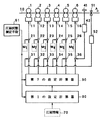
図1は本発明の一実施形態の概略構成を適用対象の圧延機と併せて示したブロック図である。同図において、圧延機1〜6が6スタンドの連続圧延機を構成し、被圧延材(以下、材料と略称する)10をA矢印方向に圧延する。これらの圧延機1〜6はそれぞれ板クラウン及び板平坦度を制御するためのアクチュエータ11〜16を備えている。このアクチュエータとしては種々のものがあるが、これを備えた代表的圧延機として次のa〜d項に示すものがある。
a.4段ミルで、上ワークロールと上バックアップロールとを対にすると共に、下ワークロールと下バックアップロールとを対にし、これらのロール対を圧延方向に相互に交叉させる機能の他に、ワークロールをベンディングさせる機能やワークロールを軸方向にシフトさせる機能等を備えた、いわゆる、ペアクロスミル。
b.4段ミルで、軸方向に直径を異ならしめたワークロールを軸方向にシフトさせる機能の他に、ワークロールをベンディングさせる機能等を有するCVC4段ミル。
c.6段ミルで、ワークロールのベンディング機能、中間ロールのベンディング機能、ワークールを軸方向にシフトする機能、中間ロールを軸方向にシフトする機能等を備える、いわゆる、6段ミル。
d.6段ミルで、ワークロールのベンディング機能、中間ロールのベンディング機能、ワークールを軸方向にシフトする機能、軸方向に直径を異ならしめた中間ロールを軸方向にシフトする機能等を備える、いわゆる、CVC6段ミル。
【0010】
図1に示すアクチュエータ11〜16は圧延機が備えるこれらの機能を総称したもので、以下の説明では、板クラウンの修正能力の大きいペアクロス角を変更する手段と、ベンディング力を変更する手段とをそれぞれ制御対象としている。この場合、アクチュエータ11〜16の制御系統には、オペレータが手動にて修正する修正値M1 〜M6 をそれぞれ入力するための加算器21〜26が設けられ、さらに、圧延中にアクチュエータ11〜15に対する板クラウンを修正するためのアクチュエータ設定値の修正量を入力する加算器31〜35と、圧延中にアクチュエータ16に対する板平坦度を修正するためのアクチュエータ設定値の修正量を入力する加算器36とが設けられている。
【0011】
一方、最終スタンドの圧延機6の出側には板平坦度計41が設けられ、検出された板平坦度が目標値に近付くように、板平坦度制御装置42がアクチュエータ16に対する設定値の修正量を加算器36に加えている。また、最終スタンドの圧延機6の出側には板クラウン計51が設けられ、検出された板クラウンが目標値に近付くように板クラウン制御装置52がアクチュエータ11〜15に対する設定値の修正量を加算器31〜35に加えている。
【0012】
なお、図示を省略するが圧延機1〜6はロール間隙を制御する圧下制御装置やロール周速を制御する主機速度制御装置を備え、さらに、圧延荷重を検出する荷重検出器、出側の板幅を検出する板幅計、板クラウン計等を備えている。ここでは、図面の簡単化のためにこれらの検出器を一纏めにして圧延状態測定手段61として表してある。そして、圧延状態測定手段61による圧延状態情報が第1の設定計算器80及び第2の設定計算器90に取込まれるようになっている。
【0013】
圧延情報70は、図示省略の上位計算機で設定される鋼種、圧延前の板厚、板幅、材料温度等の圧延前情報と、圧延後の板厚、板幅、材料温度、板クラウン、板平坦度等の目標値である圧延後情報とを総称したもので、ときにより、圧延命令書とも呼ばれ、この圧延情報70が第1の設定計算器80及び第2の設定計算器90に加えられるようになっている。
【0014】
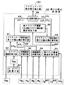
図2は第2の設定計算器90の詳細な構成を示すブロック図である。この第2の設定計算器90は先行材の圧延後であって、かつ、後行材の圧延前にアクチュエータ設定値の修正量100を演算するものである。そのために、所定の時間間隔でロールクラウンを計算すると共に、予測計算をするロールクラウン計算手段91、先行材と後行材に対するロールクラウンの偏差を求めるロールクラウン偏差計算手段92、荷重偏差計算手段93、板幅偏差計算手段94、板クラウン目標値偏差計算手段95を備え、さらに、板クラウン目標値偏差計算手段95の出力が零か否かを判別する板クラウン目標値偏差判定手段96と、ロールクラウン、荷重及び板幅の各偏差に基づいてアクチュエータの修正量を求めるアクチュエータ設定値の第1の修正量計算手段97と、板クラウン目標値の偏差に基づいてアクチュエータの修正量を求めるアクチュエータ設定値の第2の修正量計算手段98と、求められた修正量を加算して出力する加算手段99とを備えている。
【0015】
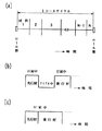
上記のように構成された本実施形態の動作について、図3をも参照して以下に説明する。
一般にタンデム圧延機では、図3(a)に示すように、ロール替から次のロール替までを1ロールサイクルと称しており、この間に材料1、材料2、・・・、材料Nという具合に連続的に圧延する場合がある。このとき、材料1と材料2とに注目すれば材料1が先行材となり、材料2が後行材となる。同様に、材料N−1と材料Nとに注目すれば材料N−1が先行材となり、材料Nが後行材となる。
【0016】
また、1ロールサイクル中の圧延形態としては、バッチ圧延と称し、図3(b)に示すように、途中に圧延していない時間、すなわち、アイドル時間を設けて圧延する場合もあり、本実施形態ではアイドル時間の直前に圧延した材料を先行材とすれば、アイドル時間の直後に圧延する材料を後行材と定義する。
【0017】
さらに、1ロールサイクル中の圧延形態としては、図3(c)に示すように、エンドレス圧延と称して先に圧延される材料の尾端と後に圧延される材料の先端とを溶接等により接合してエンドレスに圧延する場合もある。このとき、材料が互いに接合した状態で圧延されたとしても、先に圧延される材料を先行材、後に圧延される材料を後行材と定義する。
【0018】
いま、後行材の圧延前に、鋼種、圧延機入側の板厚、板幅、材料温度等の圧延前情報と、圧延機出側の板厚、板幅、材料温度、板クラウン、板平坦度等の目標値を含む圧延後情報とが圧延情報70として第1の設定計算器80及び第2の設定計算器90に加えられる。このうち、第1の設定計算器80は圧延情報70に基づき、後行材に対する圧延機1〜6の出側の板厚、板幅、圧延荷重、圧延トルク、材料温度、先進率等を設定計算し、さらに、その計算結果に基づいて圧延機1〜6の各ロール間隙、ロール周速等を設定計算して第2の設定計算器90に加えると共に、図示省略の各制御装置に加える。この場合、圧延状態測定手段61の測定値を用いて、フィードバック制御又はフィードフォワード制御等を実行するが、この点に関しては、各種提案されて公知であるのでその説明を省略する。また、板平坦度計41の検出値に基づいて板平坦度制御装置42が圧延機6のアクチュエータの設定値に対する修正量を演算して加算器36に加える点、板クラウン計51の検出値に基づいて板クラウン制御装置52が圧延機1〜5の各アクチュエータの設定値に対する修正量を演算して加算器31〜35に加える点も、各種提案されて公知であるのでその説明を省略する。
【0019】
ここでは、先行材の圧延状態に基づいて後行材の板クラウン及び板平坦度の精度を向上させるために設けた第2の設定計算器90の詳しい動作を説明する。
先行材と後行材とでは圧延前情報及び圧延後情報が異なるのが一般的である。また、圧延ロールは圧延による熱膨張、冷却による収縮、圧延による摩耗等があるためロール形状は時々刻々変化する。かかる条件下でも板クラウン及び板平坦度を目標値に一致させるために、先行材の圧延中に、好ましくはその尾端部分における板幅、圧延荷重、アクチュエータの状態量(ペアクロス角、ロールベンディング力等)、板クラウン、板平坦度を圧延状態測定手段61によって検出し第2の設定計算器90に加える。
【0020】
第2の設定計算器90を構成するロールクラウン計算手段91は、一定時間毎に、スタンド番号をi(=1〜6)として、i番目の圧延機が先行材圧延中のロールクラウンCRAiを計算すると共に、後行材を圧延する場合のロールクラウンCRBiを予測計算する。そして、ロールクラウン偏差計算手段92は次式の計算を実行してロールクラウン偏差ΔCRiを出力する。
ΔCRi=CRBi−CRAi …(1)
また、荷重偏差計算手段93はi番目の圧延機が先行材圧延中の圧延荷重の測定値PAiと、後行材を圧延する場合の圧延荷重の目標値PBiとを入力し、次式により荷重偏差ΔPiを計算する。
ΔPi=PBi−PAi …(2)
さらに、板幅偏差計算手段94は先行材圧延中の最終スタンドの圧延機6の出側の板幅の測定値WAと、後行材を圧延する場合の板幅の目標値WBとを入力し、次式により板幅偏差ΔWを計算する。
ΔW=WB−WA …(3)
また、板クラウン目標値偏差計算手段95は最終の圧延機6が先行材圧延中の最終スタンドの圧延機6の出側の板クラウンの目標値CA REFと、後行材を圧延する場合の板クラウンの目標値CB REFとを入力し、次式により板クラウン目標値偏差ΔCREFを計算する。
ΔCREF=CB REF−CA REF …(4)
一方、先行材を圧延中の尾端部ではオペレータによる修正も行われるが、圧延状態測定手段61による先行材の板クラウンの測定値が先行材の板クラウンの目標値CA REFに対して偏差ΔCAを有している場合もある。
【0021】
このとき、板クラウン目標値偏差計算手段95は次式の計算を行う。
ΔCREF =CB REF −(CA REF +ΔCA )…(5)
このΔCREF は最終スタンドの圧延機6の出側の板クラウン目標値偏差である。
【0022】
一般に、先行材と後行材とでは(1)式のロールクラウン偏差ΔCRi、(2)式の荷重偏差ΔPi 、(3)式の板幅偏差ΔWが変化するが、板クラウン目標値偏差判定手段96は板クラウン目標値偏差計算手段95のΔCREF が零か否かを判定する。すなわち、(4)式又は(5)式の板クラウン目標値偏差ΔCREF が零か否かを判定する。この場合、(4)式の板クラウン目標値偏差ΔCREF が零であることは、先行材の板クラウンの目標値と後行材の板クラウンの目標値との偏差が零であることを意味し、(5)式の板クラウン目標値偏差ΔCREF が零であることは、後行材の板クラウンの目標値と先行材の板クラウンの測定値との偏差が零であることを意味している。
【0023】
いま、(4)式又は(5)式の板クラウン目標値偏差ΔCREF が零であれば、アクチュエータ設定値の第1の修正量計算手段97のみがアクチュエータ設定値の修正量を計算し、アクチュエータ設定値の第2の修正量計算手段98は入力が零であるのでその計算を行わずその出力も零である。そこで、板クラウン目標値偏差ΔCREF が零であるものとして、第1のアクチュエータ設定値の修正量計算手段97の動作を、その原理と併せて以下に説明する。
【0024】
一般に、ロール対を圧延方向に互いに交叉させるペアクロス角は、ロールベンダーのベンディング力に比べて板クラウン修正能力は大きい。そこで先ずペアクロス角の修正量を求める場合について考える。
【0025】
iスタンドの圧延機のペアクロス角の修正量ΔXi と、上述した荷重偏差 ΔPi 、板幅偏差ΔW、ロールクラウン偏差ΔCRiとの間に下記の関係式が成立する。
【0026】
【数1】

【0027】
【数2】
【0028】
【数3】
【0029】
一方、ペアクロスミルを用いないか、あるいは、これらのアクチュエータを有していないミルではロールベンディング力Fの修正により後行材の板クラウンと板平坦度の設定値を以下のようにして求める。
【0030】
iスタンドの圧延機のロールベンダーの修正量ΔFi と、上述した荷重偏差 ΔPi 、板幅偏差ΔW、ロールクラウン偏差ΔCRiとの間に下記の関係式が成立する。
【0031】
【数4】
【0032】
【数5】
【0033】
【数6】
【0034】
以上のようにして求められたアクチュエータの設定値の修正量ΔXi 又は ΔFi は、加算手段99を介して、アクチュエータ設定値の修正量100として出力される。
【0035】
なお、ロール替の後で最初に圧延される材料に対するアクチュエータの設定値は第1の設定計算器80によって設定されるが、2番目以降に圧延される材料に対しては、先行材の尾端部の測定値が設定値となる。
【0036】
次に、(4)式又は(5)式の板クラウン目標値偏差ΔCREF が零でないとき、板クラウン目標値偏差判定手段96がそのことを示す信号をアクチュエータ設定値の第2の修正量計算手段98に加える。このアクチュエータ設定値の第2の修正量計算手段98は以下のようにして、板クラウン目標値偏差ΔCREF を零にするアクチュエータの設定値の修正量を計算する。
【0037】
ここで、板クラウン目標値偏差ΔCREF は最終スタンドの圧延機6の出側の偏差であるので、これを零にするために各スタンドの圧延機1〜6の全てのアクチュエータの設定値を修正することとする。このとき、前段スタンドの板クラウンは後段スタンドに遺伝することを考慮する必要がある。すなわち、板クラウン目標値偏差ΔCREF と、iスタンドの圧延機のアクチュエータの設定値の修正量 ΔCCTL との間に次式の関係が成立する。
【0038】
【数7】
ΔCCTL :板クラウン修正量
ΔCREF :板クラウン目標値偏差
h :圧延機の出側板厚
h6 :最終スタンドの圧延機の出側板厚
η :遺伝係数
ΔCi SUM :遺伝を考慮した後の板クラウン
α :調整係数(0<α≦1.0)
添字i:圧延機のスタンド番号
である。
【0039】
板クラウンの目標値偏差ΔCREF を零にするために、(10),(11)式を用いて各スタンドの圧延機1〜6のアクチュエータの設定値に対する修正量 ΔCi CTL を決めることは、比率クラウン修正量が一定又はある割合になるため、板平坦度が悪化しない特徴を有している。
【0040】
このようにして各スタンドの圧延機1〜6の板クラウン修正量ΔCi CTL が求まったとすれば、前述したと同様にして、アクチュエータの修正量を求めるが、板クラウンの修正能力の大きいペアクロスミルのペアクロス角の修正量 ΔXi CTL と板クラウン修正量ΔCi CTL との間に次式の関係がある。
【0041】
【数8】
【0042】
一方、ペアクロスミルを用いないか、あるいは、これと同様な手段を備えていないミルではロールベンディング力の修正により後行材の板クラウンと板平坦度の設定値を以下のようにして求める。この場合、ロールベンディング力の修正量ΔFi CTL と板クラウン修正量ΔCi CTL との間に次式の関係がある。
【0043】
【数9】
【0044】
つまり、ペアクロスミルにあっては、(7)式で求めたペアクロス角の修正量ΔXi と(14)式で求めたペアクロス角の修正量ΔXi CTL との和がアクチュエータ設定値の修正量100となる。
【0045】
そして、ペアクロスミルを用いないか、あるいは、これと同様な手段を備えていないミルでは、(9)式で求めたロールベンディング力の修正量ΔFi と(16)式で求めたロールベンディング力の修正量ΔFi CTL との和がアクチュエータ設定値の修正量100となる。
【0046】
以上の説明によって明らかなように、板クラウン目標値偏差ΔCREF が零である場合には、アクチュエータ設定値の第1の修正量計算手段97によるアクチュエータの修正量のみによる修正が行われ、板クラウン目標値偏差ΔCREF が零でない場合には、アクチュエータ設定値の第1の修正量計算手段97で求めた修正量と、アクチュエータ設定値の第2の修正量計算手段97によって求めた修正量との和の修正量による修正が行われる。
【0047】
なお、上記の実施形態では、ペアクロスミルであればクロス角を、ペアクロスミルを用いないか、あるいは、これと同様な手段を備えていないミルではベンデタィング力をそれぞれ修正する場合について説明したが、ペアクロスミルであっても、ワークロールを軸方向にシフトする機能を備えておればそのシフト量を修正しても良い。
【0048】
また、CVC4段ミルがワークロールのシフト機能とベンデイング機能の両方を備えている場合には、ベンディング機能を用いずにワークロールのシフト量を修正しても良い。
【0049】
さらに、6段ミルあるいはCVC6段ミルであっても、ベンディング機能を用いずにワークロール又は中間ロールのシフト量を修正しても良い。
【0050】
一方、上記の実施形態ではタンデムに配置された6スタンドの連続圧延機を制御対象としたが、本発明はこれに適用を限定されるものではなく、極端な場合には単一のスタンドにも適用可能であり、さらに、複数スタンドでなる殆ど全ての連続圧延機にも適用可能である。
【0051】
さらにまた、上記実施形態では最終スタンドの出側に板クラウン計を設置した場合に、上流の各スタンドのアクチュエータの設定値を修正したが、複数のスタンドの中間に板クラウン計が設けられている場合には、少なくとも、板クラウン計よりも上流のスタンドに対して上述した修正が可能であり、さらに、板クラウン計の下流のスタンドであっても、板クラウン計の後段スタンドから最終スタンドまで同様な修正を実施することできる。
【0052】
【発明の効果】
以上の説明によって明らかなように本発明によれば、先行材に対する圧延状態の各測定値と、これらの測定値に対応する後行材に対する圧延条件の各設定計算値との偏差を計算し、先行材の圧延後に後行材を圧延するに当たり、先行材の板クラウンの目標値と後行材の板クラウンの目標値との偏差、あるいは、後行材の板クラウンの目標値と先行材の板クラウンの測定値との偏差が零であるとき、先行材に対する圧延状態の各測定値と後行材に対する圧延条件の各設定計算値との偏差に基づいて後行材に対するアクチュエータの設定値を順次に修正するので、クラウン比率遺伝係数や形状変化係数を使用せずに済み、かつ、先行材の圧延結果を後行材の圧延制御に利用することによって、後続の被圧延材の板クラウンと板平坦度を高精度に目標値に仕上げることができる。
【0053】
また、もう一つの発明によれば、先行材に対する圧延状態の各測定値と、これらの測定値に対応する後行材に対する圧延条件の各設定計算値との偏差を計算し、先行材の圧延後に後行材を圧延するに当たり、最終圧延機の出側における後行材の板クラウンの目標値と先行材の板クラウンの目標値との偏差、あるいは、後行材の板クラウンの目標値と先行材の板クラウンの測定値との偏差がが零でないとき、この偏差に予め設定した調整係数を乗じ、さらに、最終の圧延機の出側の板厚に対する当該圧延機の出側の板厚の比で表される板厚比を乗じて当該圧延機までの板クラウンの設定値の修正量とし、この修正量から当該圧延機の前段圧延機までの板クラウンの設定値の修正量に当該圧延機の遺伝係数を乗じた値を減算して当該圧延機の板クラウンの修正量とし、この板クラウンの修正量に基づいてアクチュエータの設定値を順次に修正するように構成したので、上述したと同様に、クラウン比率遺伝係数や形状変化係数を使用せずに済み、かつ、先行材の圧延結果を後行材の圧延制御に有効に利用することによって、後続の被圧延材の板クラウンと板平坦度を高精度に目標値に仕上げることができる。
【図面の簡単な説明】
【図1】本発明の一実施形態の概略構成を、適用対象圧延機と併せて示したブロック図。
【図2】図1に示した実施形態の主要な要素の詳細な構成を示すブロック図。
【図3】本発明を適用する圧延機の代表的な圧延形態を説明するための説明図。
【符号の説明】
1〜6 圧延機
11〜16 アクチュエータ
21〜26,31〜36 加算器
41 板平坦度計
42 板平坦度制御装置
51 板クラウン計
52 板クラウン制御装置
61 圧延状態測定手段
80 第1の設定計算器
90 第2の設定計算器
91 ロールクラウン計算手段
92 ロールクラウン偏差計算手段
93 荷重偏差計算手段
94 板幅偏差計算手段
95 板クラウン目標値偏差計算手段
96 板クラウン目標値偏差判定手段
97 アクチュエータ設定値の第1の修正量計算手段
98 アクチュエータ設定値の第2の修正量計算手段
99 加算手段[0001]
BACKGROUND OF THE INVENTION
The present invention relates to control of a rolling mill suitable for a continuous rolling mill arranged in tandem, and more particularly to a control method and a control apparatus for a rolling mill to obtain a plate with a desired plate crown and plate flatness.
[0002]
[Prior art]
As this type of prior art, for example, the Japan Iron and Steel Institute Rolling Theory Division Journal 100th Symposium “Development of Rolling Technology and Rolling Theory and Future Trends” (June 1994), pages 79 to 90 The page describes a high-precision rolling technology in a hot strip mill (written by Yasuyuki Nishiyama, Shinji Shibao, Satoshi Shimazu et al.) And describes a control system for achieving the target plate crown and target plate shape. As an initial setting function, this control system has a function of obtaining initial setting values of the roll cross angle and roll bending force of each stand that achieve the target plate crown and target plate shape.
[0003]
[Problems to be solved by the invention]
The control system described above uses crown ratio genetic coefficients and shape coefficients to improve the thickness accuracy in the sheet width direction, but it is difficult to actually obtain these coefficients.
In addition, the above-described control system uses the rolling result of the preceding material that is rolled earlier in time among the rolled materials that are sequentially rolled by the rolling mill, for rolling the subsequent material that is rolled later in time. There was no description about the points to be performed, and there was no description when the rolling conditions were different between the preceding material and the following material.
[0004]
The present invention has been made to solve the above-mentioned problems, and it is not necessary to use the crown ratio genetic coefficient or the shape change coefficient, and the rolling result of the preceding material is effectively used for the rolling control of the succeeding material. Accordingly, an object of the present invention is to provide a control method and a control device for a rolling mill that can finish the plate crown and flatness of the subsequent rolled material to the target values with high accuracy.
[0005]
[Means for Solving the Problems]
The first invention for achieving the above object is to control a plurality of rolling mills arranged in tandem and each having an actuator for controlling a sheet crown.
Based on the rolling information given from the outside, before rolling the material to be rolled, rolling conditions including the rolling load, the target value of the sheet width and the sheet crown, and the set value of the actuator for the material to be rolled first are set. Calculate settings,
During rolling of the material to be rolled, measure the rolling state including rolling load, plate width and plate crown,
Of the material to be rolled in order by a rolling mill, the material to be rolled earlier in time is the preceding material, the material to be rolled later in time is the succeeding material, and the rolling state of the preceding material is Calculate the deviation between each measured value and each calculated value of rolling conditions for the following material corresponding to these measured values,
When rolling the succeeding material after rolling the preceding material, when the deviation between the target value of the sheet crown of the preceding material and the target value of the sheet crown of the succeeding material is zero, each measured value of the rolling state with respect to the preceding material and The actuator setting values for the succeeding material are sequentially corrected based on the deviation from each setting calculation value of the rolling conditions for the succeeding material.
It is comprised as follows.
[0006]
In this case, instead of providing that the deviation between the target value of the leading plate crown and the target value of the trailing plate crown is zero, the target value of the trailing plate crown and the leading plate It may be a condition that the deviation from the measured value of the crown is zero.
[0007]
In order to achieve the above object, a second invention has an actuator arranged in tandem, each for controlling a plate crown.pluralIn controlling the rolling mill,
Based on the rolling information given from the outside, before rolling the material to be rolled, rolling conditions including the rolling load, the target value of the sheet width and the sheet crown, and the set value of the actuator for the material to be rolled first are set. Calculate settings,
During rolling of the material to be rolled, measure the rolling state including rolling load, plate width and plate crown,
Of the material to be rolled in order by a rolling mill, the material to be rolled earlier in time is the preceding material, the material to be rolled later in time is the succeeding material, and the rolling state of the preceding material is Calculate the deviation between each measured value and each calculated value of rolling conditions for the following material corresponding to these measured values,
When rolling the succeeding material after rolling the preceding material, if the deviation between the target value of the sheet crown of the succeeding material and the target value of the sheet crown of the preceding material is not zero on the delivery side of the final rolling mill, Multiply by the set adjustment factor, and further multiply by the plate thickness ratio represented by the ratio of the plate thickness on the exit side of the rolling mill to the plate thickness on the exit side of the final rolling mill, the set value of the plate crown of the rolling mill A correction amount of the sheet crown of the rolling mill by adding the correction amount and a correction value of the set value of the plate crown of the preceding rolling mill of the rolling mill multiplied by the genetic coefficient of the rolling mill And sequentially correct the actuator set values based on the correction amount of the plate crown.
It is comprised as follows.
[0008]
In this case, instead of being provided that the deviation between the target value of the plate crown of the following material and the target value of the plate crown of the preceding material on the delivery side of the final rolling mill is not zero, the target of the plate crown of the following material The deviation between the measured value and the measured value of the plate crown of the preceding material may not be zero.
[0009]
DETAILED DESCRIPTION OF THE INVENTION
Hereinafter, the present invention will be described in detail based on preferred embodiments.
FIG. 1 is a block diagram showing a schematic configuration of an embodiment of the present invention together with a rolling mill to be applied. In the figure,
a. In addition to pairing the upper work roll and the upper backup roll with the four-stage mill, pairing the lower work roll and the lower backup roll, and crossing these roll pairs with each other in the rolling direction, the work roll A so-called pair cross mill equipped with a function to bend the workpiece and a function to shift the work roll in the axial direction.
b. A 4-stage mill, a CVC 4-stage mill that has a function of bending a work roll in addition to a function of shifting a work roll having a different diameter in the axial direction in the axial direction.
c. A so-called six-stage mill having a function of bending a work roll, a function of bending an intermediate roll, a function of shifting the work roll in the axial direction, a function of shifting the intermediate roll in the axial direction, and the like.
d. The so-called CVC6, which has a 6-stage mill, a work roll bending function, an intermediate roll bending function, a function for shifting the work roll in the axial direction, and a function for shifting the intermediate roll with different diameters in the axial direction in the axial direction. Step mill.
[0010]
The
[0011]
On the other hand, a
[0012]
Although not shown, the
[0013]
Rolling information 70 includes steel type set by a host computer (not shown), sheet thickness before rolling, sheet width, material temperature, and other information before rolling, sheet thickness after rolling, sheet width, material temperature, sheet crown, sheet It is a generic term for post-rolling information that is a target value such as flatness, and is sometimes called a rolling instruction, and this rolling information 70 is added to the first setting calculator 80 and the
[0014]
FIG. 2 is a block diagram showing a detailed configuration of the
[0015]
The operation of the present embodiment configured as described above will be described below with reference to FIG.
In general, in a tandem rolling mill, as shown in FIG. 3A, from one roll change to the next roll change is referred to as one roll cycle, and during this time,
[0016]
Moreover, as a rolling form in 1 roll cycle, it is called batch rolling, and as shown in FIG.3 (b), the time which is not rolled in the middle, ie, an idle time, may be provided, and this implementation may be carried out. In the embodiment, if the material rolled immediately before the idle time is the preceding material, the material rolled immediately after the idle time is defined as the trailing material.
[0017]
Furthermore, as a rolling form in one roll cycle, as shown in FIG. 3C, the tail end of the material rolled first and the tip of the material rolled later are joined by welding or the like as shown in endless rolling. And sometimes rolling endlessly. At this time, even if the materials are rolled in a state of being bonded to each other, the material that is rolled first is defined as the preceding material, and the material that is rolled later is defined as the following material.
[0018]
Now, before rolling the following material, pre-rolling information such as steel grade, rolling mill inlet side plate thickness, strip width, material temperature, rolling mill outlet side plate thickness, strip width, material temperature, strip crown, strip Post-rolling information including a target value such as flatness is added to the first setting calculator 80 and the
[0019]
Here, the detailed operation of the
Generally, information before rolling and information after rolling are different between the preceding material and the following material. Further, since the rolling roll has thermal expansion due to rolling, shrinkage due to cooling, wear due to rolling, and the like, the roll shape changes every moment. In order to make the plate crown and plate flatness coincide with the target values even under such conditions, the plate width, rolling load, and actuator state quantity (pair cross angle, roll bending force at the tail end portion thereof are preferable during rolling of the preceding material. Etc.), the plate crown and the flatness of the plate are detected by the rolling state measuring means 61 and added to the
[0020]
The roll crown calculation means 91 which comprises the
ΔCRi= CRBi-CRAi ... (1)
The load deviation calculating means 93 is a measured value P of the rolling load during the rolling of the preceding material by the i-th rolling mill.AiAnd the rolling load target value P when rolling the following materialBiAnd the load deviation ΔPiCalculate
ΔPi= PBi-PAi ... (2)
Further, the sheet width deviation calculating means 94 is a measured value W of the sheet width on the exit side of the rolling
ΔW = WB-WA ... (3)
Further, the plate crown target value deviation calculating means 95 is provided for the plate crown on the exit side of the rolling
ΔCREF= CB REF-CA REF ... (4)
On the other hand, the tail end during rolling of the preceding material is also corrected by the operator.Leading materialThe measured value of the plate crown isOf the crown of the leading materialTarget value CA REFDeviation ΔCAMay have.
[0021]
At this time, the plate crown target value deviation calculating means 95 calculates the following equation.
ΔCREF= CB REF-(CA REF+ ΔCA) ... (5)
This ΔCREFIs the plate crown target value deviation on the exit side of the rolling
[0022]
In general, the roll crown deviation ΔC of the equation (1) between the preceding material and the following materialRi, (2) load deviation ΔPi, The plate width deviation ΔW in the equation (3) changes, but the plate crown target value
[0023]
Now, the plate crown target value deviation ΔC in the equation (4) or (5)REFIs zero, only the first correction amount calculation means 97 for the actuator setting value calculates the correction amount for the actuator setting value, and the second correction amount calculation means 98 for the actuator setting value has zero input. No calculation is performed and the output is zero. Therefore, the plate crown target value deviation ΔCREFThe operation of the first actuator set value correction amount calculation means 97 will be described below together with the principle thereof, assuming that is zero.
[0024]
In general, the pair cross angle at which the roll pairs cross each other in the rolling direction has a larger plate crown correcting ability than the bending force of the roll bender. First, consider the case of obtaining the correction amount of the pair cross angle.
[0025]
Correction amount ΔX of pair cross angle of i-stand rolling milliAnd the load deviation ΔP described abovei, Plate width deviation ΔW, roll crown deviation ΔCRiThe following relational expression holds between
[0026]
[Expression 1]
[0027]
[Expression 2]
[0028]
[Equation 3]
[0029]
On the other hand, in a mill that does not use a pair cross mill or does not have these actuators, the set values of the plate crown and plate flatness of the succeeding material are obtained as follows by correcting the roll bending force F.
[0030]
iFolder roll bender correction amount ΔFiAnd the load deviation ΔP described abovei, Plate width deviation ΔW, roll crown deviation ΔCRiThe following relational expression holds between
[0031]
[Expression 4]
[0032]
[Equation 5]
[0033]
[Formula 6]
[0034]
Actuator setting value correction amount ΔX obtained as described aboveiOr ΔFiIs output as an actuator set
[0035]
The set value of the actuator for the material rolled first after the roll change is set by the first setting calculator 80, but the tail end of the preceding material is set for the material rolled after the second. The measured value of the part becomes the set value.
[0036]
Next, the plate crown target value deviation ΔC in the equation (4) or (5)REFIs not zero, the plate crown target value
[0037]
Here, the plate crown target value deviation ΔCREFIs a deviation on the exit side of the rolling
[0038]
[Expression 7]
ΔCCTL : Crown correction amount
ΔCREF : Plate crown target value deviation
h: Outboard thickness of rolling mill
h6 : Outboard thickness of the rolling mill at the final stand
η: Genetic coefficient
ΔCi SUM: Crown after taking into account heredity
α: Adjustment coefficient (0 <α ≦ 1.0)
Subscript i: Stand number of rolling mill
It is.
[0039]
Target value deviation ΔC of plate crownREFIn order to make the value zero, the correction amount ΔC with respect to the set value of the actuator of the
[0040]
In this way, the crown correction amount ΔC of the
[0041]
[Equation 8]
[0042]
On the other hand, in a mill that does not use a pair cross mill or that does not have the same means, the set values of the plate crown and plate flatness of the following material are obtained as follows by correcting the roll bending force. In this case, the correction amount ΔF of the roll bending forcei CTLAnd plate crown correction amount ΔCi CTLThere is a relationship of
[0043]
[Equation 9]
[0044]
That is, in the case of a pair cross mill, the correction amount ΔX of the pair cross angle obtained by the equation (7)iAnd the correction amount ΔX of the pair cross angle obtained by the equation (14)i CTLIs a
[0045]
In a mill that does not use a pair cross mill or that does not have the same means as this, the correction amount ΔF of the roll bending force obtained by the equation (9)iAnd the correction amount ΔF of the roll bending force obtained by the equation (16)i CTLIs a
[0046]
As apparent from the above explanation, the plate crown target value deviation ΔCREFIs zero, the actuator setting value is corrected only by the actuator correction amount by the first correction amount calculation means 97, and the plate crown target value deviation ΔC is corrected.REFIs not zero, the correction amount is the sum of the correction amount obtained by the first correction
[0047]
In the above-described embodiment, the case has been described in which the cross angle is corrected in the case of a pair cross mill, and the bending force is corrected in a mill that does not use a pair cross mill or a mill that does not have the same means as this. Even in the case of a pair cross mill, the shift amount may be corrected if it has a function of shifting the work roll in the axial direction.
[0048]
Further, when the CVC four-stage mill has both the work roll shift function and the bending function, the shift amount of the work roll may be corrected without using the bending function.
[0049]
Further, even in a 6-stage mill or a CVC 6-stage mill, the shift amount of the work roll or the intermediate roll may be corrected without using the bending function.
[0050]
On the other hand, in the above embodiment, a six-stand continuous rolling mill arranged in tandem is a control target. However, the present invention is not limited to this, and in an extreme case, a single stand can be used. Further, the present invention can be applied to almost all continuous rolling mills having a plurality of stands.
[0051]
Furthermore, in the above embodiment, when the plate crown meter is installed on the exit side of the final stand, the set value of the actuator of each upstream stand is corrected, but the plate crown meter is provided in the middle of the plurality of stands. In this case, at least the above-mentioned correction can be made to the stand upstream of the plate crown meter, and even the stand downstream of the plate crown meter is the same from the rear stand to the final stand of the plate crown meter. Corrections can be made.
[0052]
【The invention's effect】
As is apparent from the above description, according to the present invention, the deviation between each measured value of the rolling state with respect to the preceding material and each setting calculation value of the rolling condition with respect to the subsequent material corresponding to these measured values is calculated, When rolling the succeeding material after rolling the preceding material, the deviation between the target value of the leading plate crown and the target value of the trailing plate crown, or the target value of the trailing plate crown and the leading material When the deviation from the measured value of the plate crown is zero, the actuator set value for the succeeding material is determined based on the deviation between the measured value of the rolling condition for the preceding material and the calculated setting values of the rolling condition for the succeeding material. Since the correction is made sequentially, it is not necessary to use the crown ratio genetic coefficient and the shape change coefficient, and the rolling result of the preceding material is used for the rolling control of the succeeding material, so that Highly accurate plate flatness It can be finished in value.
[0053]
Further, according to another invention, the deviation between each measured value of the rolling state for the preceding material and each set calculation value of the rolling condition for the subsequent material corresponding to these measured values is calculated, and the rolling of the preceding material is calculated. When rolling the subsequent material later, the deviation between the target value of the plate crown of the subsequent material and the target value of the plate crown of the preceding material on the exit side of the final rolling mill, or the target value of the plate crown of the subsequent material When the deviation from the measured value of the sheet crown of the preceding material is not zero, the deviation is multiplied by a preset adjustment factor, and the thickness of the delivery side of the rolling mill with respect to the thickness of the delivery side of the final rolling mill Multiplying the plate thickness ratio represented by the ratio, the amount of correction of the setting value of the plate crown up to the rolling mill is calculated, and the amount of correction of the setting value of the plate crown from the correction amount to the preceding rolling mill of the rolling mill Subtracting the value multiplied by the genetic coefficient of the rolling mill, As described above, it is not necessary to use the crown ratio genetic coefficient and the shape change coefficient as described above. And by effectively utilizing the rolling result of the preceding material for the rolling control of the succeeding material, the plate crown and the flatness of the subsequent material to be rolled can be finished to the target values with high accuracy.
[Brief description of the drawings]
FIG. 1 is a block diagram showing a schematic configuration of an embodiment of the present invention together with an applicable rolling mill.
FIG. 2 is a block diagram showing a detailed configuration of main elements of the embodiment shown in FIG. 1;
FIG. 3 is an explanatory diagram for explaining a typical rolling form of a rolling mill to which the present invention is applied.
[Explanation of symbols]
1-6 Rolling mill
11-16 Actuator
21-26, 31-36 Adder
41 Plate flatness meter
42 Plate flatness control device
51 crown meter
52 Crown control device
61 Rolling state measuring means
80 First setting calculator
90 Second setting calculator
91 Roll crown calculation means
92 Roll crown deviation calculating means
93 Load deviation calculation means
94 Plate width deviation calculation means
95 Plate crown target value deviation calculating means
96 Plate crown target value deviation judging means
97 Actuator setting value first correction amount calculation means
98 Second correction amount calculation means for actuator set value
99 addition means
Claims (14)
外部から与えられた圧延情報に基づいて、被圧延材の圧延前に、圧延荷重、板幅及び板クラウンの目標値、並びに最初に圧延される被圧延材に対する前記アクチュエータの設定値を含む圧延条件を設定計算し、
被圧延材の圧延中に、圧延荷重、板幅及び板クラウンを含む圧延状態を測定し、
前記圧延機により順に圧延される被圧延材のうち、時間的に先に圧延される被圧延材を先行材、時間的に後に圧延される被圧延材を後行材とし、先行材に対する圧延状態の各測定値と、これらの測定値に対応する後行材に対する圧延条件の各設定計算値との偏差を計算し、
先行材の圧延後に後行材を圧延するに当たり、先行材の板クラウンの目標値と後行材の板クラウンの目標値との偏差が零であるとき、先行材に対する圧延状態の各測定値と後行材に対する圧延条件の各設定計算値との偏差に基づいて後行材に対する前記アクチュエータの設定値を順次に修正する、
ことを特徴とする圧延機の制御方法。In a control method of a plurality of rolling mills arranged in tandem, each having an actuator for controlling the plate crown,
Based on the rolling information given from the outside, before rolling the material to be rolled, rolling conditions including the rolling load, the target value of the sheet width and the sheet crown, and the set value of the actuator for the material to be rolled first Calculate the settings and
During rolling of the material to be rolled, measure the rolling state including rolling load, plate width and plate crown,
Of the material to be rolled in order by the rolling mill, the material to be rolled earlier in time is the preceding material, the material to be rolled later in time is the subsequent material, and the rolled state for the preceding material Calculate the deviation between each measured value of and the calculated calculated values of rolling conditions for the succeeding material corresponding to these measured values,
When rolling the succeeding material after rolling the preceding material, when the deviation between the target value of the sheet crown of the preceding material and the target value of the sheet crown of the succeeding material is zero, each measured value of the rolling state with respect to the preceding material and Sequentially correcting the setting values of the actuator for the succeeding material based on deviations from the respective calculated calculation values of the rolling conditions for the succeeding material,
A control method for a rolling mill.
外部から与えられた圧延情報に基づいて、被圧延材の圧延前に、圧延荷重、板幅及び板クラウンの目標値、並びに最初に圧延される被圧延材に対する前記アクチュエータの設定値を含む圧延条件を設定計算し、
被圧延材の圧延中に、圧延荷重、板幅及び板クラウンを含む圧延状態を測定し、
前記圧延機により順に圧延される被圧延材のうち、時間的に先に圧延される被圧延材を先行材、時間的に後に圧延される被圧延材を後行材とし、先行材に対する圧延状態の各測定値と、これらの測定値に対応する後行材に対する圧延条件の各設定計算値との偏差を計算し、
先行材の圧延後に後行材を圧延するに当たり、最終圧延機の出側における後行材の板クラウンの目標値と先行材の板クラウンの目標値との偏差が零でないとき、この偏差に予め設定した調整係数を乗じ、さらに、最終の圧延機の出側の板厚に対する当該圧延機の出側の板厚の比で表される板厚比を乗じて当該圧延機までの板クラウンの設定値の修正量とし、この修正量から当該圧延機の前段圧延機までの板クラウンの設定値の修正量に当該圧延機の遺伝係数を乗じた値を減算して当該圧延機の板クラウンの修正量とし、この板クラウンの修正量に基づいて前記アクチュエータの設定値を順次に修正する、
ことを特徴とする圧延機の制御方法。In a control method of a plurality of rolling mills arranged in tandem, each having an actuator for controlling the plate crown,
Based on the rolling information given from the outside, before rolling the material to be rolled, rolling conditions including the rolling load, the target value of the sheet width and the sheet crown, and the set value of the actuator for the material to be rolled first Calculate the settings and
During rolling of the material to be rolled, measure the rolling state including rolling load, plate width and plate crown,
Of the material to be rolled in order by the rolling mill, the material to be rolled earlier in time is the preceding material, the material to be rolled later in time is the subsequent material, and the rolled state for the preceding material Calculate the deviation between each measured value of and the calculated calculated values of rolling conditions for the succeeding material corresponding to these measured values,
When rolling the succeeding material after rolling the preceding material, if the deviation between the target value of the sheet crown of the succeeding material and the target value of the sheet crown of the preceding material is not zero on the delivery side of the final rolling mill, Multiplying the set adjustment factor, and then multiplying the plate thickness ratio represented by the ratio of the plate thickness on the exit side of the rolling mill to the plate thickness on the exit side of the final rolling mill to set the plate crown up to the rolling mill The amount of correction of the value, and the value obtained by multiplying the amount of correction of the set value of the sheet crown from the amount of correction to the preceding rolling mill of the rolling mill by the genetic coefficient of the rolling mill is subtracted. And the actuator set value is sequentially corrected based on the correction amount of the plate crown,
A control method for a rolling mill.
外部から与えられた圧延情報に基づいて、被圧延材の圧延前に、圧延荷重、板幅及び板クラウンの目標値、並びに最初に圧延される被圧延材に対する前記アクチュエータの設定値を含む圧延条件を設定計算する第1の設定計算手段と、
被圧延材の圧延中に、圧延荷重、板幅及び板クラウンを含む圧延状態を測定する圧延状態測定手段と、
前記圧延機により順に圧延される被圧延材のうち、時間的に先に圧延される被圧延材を先行材、時間的に後に圧延される被圧延材を後行材とし、先行材に対する圧延状態の各測定値と、これらの測定値に対応する後行材に対する圧延条件の各設定計算値との偏差を計算し、先行材の圧延後に後行材を圧延するに当たり、先行材の板クラウンの目標値と後行材の板クラウンの目標値との偏差が零であるとき、先行材に対する圧延状態の各測定値と後行材に対する圧延条件の各設定計算値との偏差に基づいて後行材に対する前記アクチュエータの設定値を順次に修正する第2の設定計算手段と、
を備えたことを特徴とする圧延機の制御装置。In a control device for a plurality of rolling mills arranged in tandem, each having an actuator for controlling the plate crown,
Based on the rolling information given from the outside, before rolling the material to be rolled, rolling conditions including the rolling load, the target value of the sheet width and the sheet crown, and the set value of the actuator for the material to be rolled first First setting calculation means for setting and calculating;
During rolling of the material to be rolled, a rolling state measuring means for measuring a rolling state including a rolling load, a sheet width and a sheet crown;
Of the material to be rolled in order by the rolling mill, the material to be rolled earlier in time is the preceding material, the material to be rolled later in time is the subsequent material, and the rolled state for the preceding material When the following material is rolled after the rolling of the preceding material, the deviation of each measured value of the following material and each setting calculation value of the rolling conditions for the following material corresponding to these measured values is calculated. When the deviation between the target value and the target value of the sheet crown of the succeeding material is zero, the following is based on the deviation between each measured value of the rolling state for the preceding material and each set calculation value of the rolling condition for the succeeding material. Second setting calculation means for sequentially correcting the setting values of the actuator for the material;
A control apparatus for a rolling mill, comprising:
外部から与えられた圧延情報に基づいて、被圧延材の圧延前に、圧延荷重、板幅及び板クラウンの目標値及び並びに最初に圧延される被圧延材に対する前記アクチュエータの設定値を含む圧延条件を設定計算する第1の設定計算手段と、
被圧延材の圧延中に、圧延荷重、板幅及び板クラウンを含む圧延状態を測定する圧延状態測定手段と、
前記圧延機により順に圧延される被圧延材のうち、時間的に先に圧延される被圧延材を先行材、時間的に後に圧延される被圧延材を後行材とし、先行材に対する圧延状態の各測定値と、これらの測定値に対応する後行材に対する圧延条件の各設定計算値との偏差を計算し、先行材の圧延後に後行材を圧延するに当たり、最終圧延機の出側における後行材の板クラウンの目標値と先行材の板クラウンの目標値との偏差が零でないことを条件として、この偏差に予め設定した調整係数を乗じ、さらに、最終の圧延機の出側の板厚に対する当該圧延機の出側の板厚の比で表される板厚比を乗じて当該圧延機までの板クラウンの設定値の修正量とし、この修正量から当該圧延機の前段圧延機までの板クラウンの設定値の修正量に当該圧延機の遺伝係数を乗じた値を減算して当該圧延機の板クラウンの追加の修正量とし、この板クラウンの修正量に基づいて前記アクチュエータの設定値を順次に修正する第2の設定計算手段と、
を備えたことを特徴とする圧延機の制御装置。In a control device for a plurality of rolling mills arranged in tandem, each having an actuator for controlling the plate crown,
Based on the rolling information given from the outside, before rolling the material to be rolled, rolling conditions including the rolling load, the target value of the sheet width and the sheet crown, and the set value of the actuator for the material to be rolled first First setting calculation means for setting and calculating;
During rolling of the material to be rolled, a rolling state measuring means for measuring a rolling state including a rolling load, a sheet width and a sheet crown;
Of the material to be rolled in order by the rolling mill, the material to be rolled earlier in time is the preceding material, the material to be rolled later in time is the subsequent material, and the rolled state for the preceding material The deviation of each measured value of each and the calculated calculation values of the rolling conditions for the succeeding material corresponding to these measured values is calculated, and in rolling the succeeding material after rolling the preceding material, the exit side of the final rolling mill On the condition that the deviation between the target value of the plate crown of the succeeding material and the target value of the plate crown of the preceding material is not zero, the deviation is multiplied by a preset adjustment factor, and the delivery side of the final rolling mill The sheet thickness ratio represented by the ratio of the sheet thickness on the outlet side of the rolling mill to the sheet thickness of the rolling mill is used as a correction amount for the set value of the sheet crown up to the rolling mill. From this correction amount, the preceding stage rolling of the rolling mill The genetic coefficient of the rolling mill The value obtained by multiplying by subtracting the additional correction amount of strip crown of the rolling mill, and a second setting calculation means for sequentially modifying the setting value of the actuator on the basis of the amount of correction of the plate crown,
A control apparatus for a rolling mill, comprising:
Priority Applications (5)
| Application Number | Priority Date | Filing Date | Title |
|---|---|---|---|
| JP00578897A JP3607029B2 (en) | 1997-01-16 | 1997-01-16 | Rolling mill control method and control apparatus |
| AU52113/98A AU697496B2 (en) | 1997-01-16 | 1998-01-16 | Method and apparatus for the control of rolling mills |
| US09/008,301 US5960657A (en) | 1997-01-16 | 1998-01-16 | Method and apparatus for the control of rolling mills |
| KR1019980001730A KR100257243B1 (en) | 1997-01-16 | 1998-01-16 | Method and device for controlling the rolling mill |
| CN98104152A CN1103649C (en) | 1997-01-16 | 1998-01-16 | Control method and control apparatus for rolling mill |
Applications Claiming Priority (1)
| Application Number | Priority Date | Filing Date | Title |
|---|---|---|---|
| JP00578897A JP3607029B2 (en) | 1997-01-16 | 1997-01-16 | Rolling mill control method and control apparatus |
Publications (2)
| Publication Number | Publication Date |
|---|---|
| JPH10192929A JPH10192929A (en) | 1998-07-28 |
| JP3607029B2 true JP3607029B2 (en) | 2005-01-05 |
Family
ID=11620844
Family Applications (1)
| Application Number | Title | Priority Date | Filing Date |
|---|---|---|---|
| JP00578897A Expired - Lifetime JP3607029B2 (en) | 1997-01-16 | 1997-01-16 | Rolling mill control method and control apparatus |
Country Status (5)
| Country | Link |
|---|---|
| US (1) | US5960657A (en) |
| JP (1) | JP3607029B2 (en) |
| KR (1) | KR100257243B1 (en) |
| CN (1) | CN1103649C (en) |
| AU (1) | AU697496B2 (en) |
Cited By (1)
| Publication number | Priority date | Publication date | Assignee | Title |
|---|---|---|---|---|
| CN102632087A (en) * | 2012-03-31 | 2012-08-15 | 中国钢研科技集团有限公司 | Method for controlling plate shape during rolling of plate type strip |
Families Citing this family (29)
| Publication number | Priority date | Publication date | Assignee | Title |
|---|---|---|---|---|
| JP3348826B2 (en) * | 1997-12-04 | 2002-11-20 | 川崎製鉄株式会社 | Setting method of rolling condition of hot rolled material |
| JP2000033411A (en) * | 1998-07-21 | 2000-02-02 | Toshiba Corp | Apparatus for measuring genetic coefficient in rolling |
| JP2000061520A (en) * | 1998-08-25 | 2000-02-29 | Toshiba Corp | Flatness control device for hot rolling mill |
| JP2000167615A (en) * | 1998-12-03 | 2000-06-20 | Toshiba Corp | Winding temperature control method and control device |
| US6230532B1 (en) * | 1999-03-31 | 2001-05-15 | Kawasaki Steel Corporation | Method and apparatus for controlling sheet shape in sheet rolling |
| DE50009532D1 (en) * | 1999-08-06 | 2005-03-24 | Muhr & Bender Kg | Method for flexible rolling of a metal strip |
| ATE255964T1 (en) * | 1999-12-23 | 2003-12-15 | Abb Ab | METHOD AND DEVICE FOR PLANNING CONTROL |
| EP1987942A3 (en) * | 2000-09-21 | 2009-12-23 | Toray Industries Inc. | A sheet obtained by extruding and molding a raw material |
| KR100848650B1 (en) * | 2001-12-24 | 2008-07-28 | 주식회사 포스코 | Control method of plate thickness change according to circumferential speed and temperature |
| KR101161700B1 (en) * | 2004-07-09 | 2012-07-03 | 가부시끼가이샤 히다치 세이사꾸쇼 | Crown control apparatus and its method of hot rolling mill |
| JP4049765B2 (en) * | 2004-07-09 | 2008-02-20 | 株式会社日立製作所 | Crown control device and control method for hot rolling mill |
| KR100832971B1 (en) * | 2006-12-05 | 2008-05-27 | 주식회사 포스코 | Bending force control method of rolling roll in continuous rolling |
| JP4606437B2 (en) * | 2007-06-28 | 2011-01-05 | 株式会社日立製作所 | Apparatus and method for crown control of hot rolling mill |
| EP2145703B1 (en) * | 2008-03-14 | 2015-01-07 | Nippon Steel & Sumitomo Metal Corporation | Rolling load prediction learning method for hot plate rolling |
| CN101966535B (en) * | 2009-07-28 | 2012-11-14 | 宝山钢铁股份有限公司 | Cold rolling strip shape forward control setting method based on incoming material plate profile |
| DE102009043400A1 (en) * | 2009-09-29 | 2011-04-07 | Siemens Aktiengesellschaft | Method for the model-based determination of actuator setpoints for the asymmetric actuators of the rolling mills of a hot strip mill |
| DE102009043401A1 (en) * | 2009-09-29 | 2011-04-07 | Siemens Aktiengesellschaft | Method for the model-based determination of actuator setpoints for the symmetrical and asymmetric actuators of the rolling mills of a hot strip mill |
| CN102665948B (en) * | 2009-10-21 | 2014-11-05 | 东芝三菱电机产业系统株式会社 | Control setting device and control setting method |
| JP5325189B2 (en) * | 2010-10-04 | 2013-10-23 | 株式会社日立製作所 | Tandem mill crown control apparatus and method |
| CN103920719B (en) * | 2013-01-11 | 2015-12-02 | 宝山钢铁股份有限公司 | The convex degree control method of hot rolled plate shape |
| ES2618487T3 (en) * | 2013-03-25 | 2017-06-21 | Abb Schweiz Ag | Procedure and control system to adjust the flatness control in a rolling mill |
| CN104096714B (en) * | 2013-04-11 | 2016-06-29 | 宝山钢铁股份有限公司 | A kind of hot-strip convexity autocontrol method |
| CN104785536B (en) * | 2014-01-21 | 2017-06-23 | 宝山钢铁股份有限公司 | A kind of method for suppressing convexity fluctuation at hot-strip watermark point |
| KR102122217B1 (en) * | 2015-03-16 | 2020-06-12 | 에스엠에스 그룹 게엠베하 | Method for manufacturing a metal strip |
| CN109663817B (en) * | 2018-11-19 | 2020-02-07 | 包头钢铁(集团)有限责任公司 | Transverse thickness precision control method of wide and thick plate flat roller mill |
| CN113020286B (en) * | 2021-02-05 | 2023-09-15 | 首钢集团有限公司 | A rolling process stability control method and device |
| CN113020284B (en) * | 2021-03-18 | 2023-04-14 | 鞍钢股份有限公司 | A method for controlling the convexity of hot-rolled raw plate for cold-rolled galvanizing |
| CN116921451B (en) * | 2023-06-26 | 2025-12-09 | 本溪北营钢铁(集团)股份有限公司 | Roller profile curve control method for convexity of lifting plate |
| CN117960797B (en) * | 2024-04-02 | 2024-06-04 | 远景睿泰动力技术(上海)有限公司 | A roller press control method, system and device |
Family Cites Families (10)
| Publication number | Priority date | Publication date | Assignee | Title |
|---|---|---|---|---|
| SE446952B (en) * | 1980-04-25 | 1986-10-20 | Asea Ab | CONTROL DEVICE FOR TAPE OR PLATFORM |
| JPH0626723B2 (en) * | 1986-09-24 | 1994-04-13 | 三菱電機株式会社 | Plate shape control method |
| JP2819202B2 (en) * | 1991-05-28 | 1998-10-30 | 住友金属工業株式会社 | How to change the roll cross angle and roll bend force between runs |
| JPH0523723A (en) * | 1991-07-24 | 1993-02-02 | Toshiba Corp | Flatness measuring device and controller for continuous rolling mill using the flatness measuring device |
| JP3254067B2 (en) * | 1993-05-07 | 2002-02-04 | 川崎製鉄株式会社 | Control method of sheet crown in endless rolling |
| JPH0724512A (en) * | 1993-07-12 | 1995-01-27 | Nkk Corp | Crown shape control method when changing hot running plate thickness |
| US5493885A (en) * | 1994-03-10 | 1996-02-27 | Kawasaki Steel Corporation | Method and apparatus for controlling rolling process in hot strip finish rolling mill |
| US5546779A (en) * | 1994-03-24 | 1996-08-20 | Danieli United, Inc. | Interstand strip gauge and profile conrol |
| JPH0899103A (en) * | 1994-09-29 | 1996-04-16 | Kobe Steel Ltd | Method for controlling sheet crown and shape in sheet rolling |
| EP0791411B1 (en) * | 1995-12-26 | 2008-02-13 | Toshiba Mitsubishi-Electric Industrial Systems Corporation | Strip crown measuring method and control method for continuous rolling machines |
-
1997
- 1997-01-16 JP JP00578897A patent/JP3607029B2/en not_active Expired - Lifetime
-
1998
- 1998-01-16 AU AU52113/98A patent/AU697496B2/en not_active Expired
- 1998-01-16 CN CN98104152A patent/CN1103649C/en not_active Expired - Lifetime
- 1998-01-16 US US09/008,301 patent/US5960657A/en not_active Expired - Lifetime
- 1998-01-16 KR KR1019980001730A patent/KR100257243B1/en not_active Expired - Lifetime
Cited By (2)
| Publication number | Priority date | Publication date | Assignee | Title |
|---|---|---|---|---|
| CN102632087A (en) * | 2012-03-31 | 2012-08-15 | 中国钢研科技集团有限公司 | Method for controlling plate shape during rolling of plate type strip |
| CN102632087B (en) * | 2012-03-31 | 2014-09-24 | 中国钢研科技集团有限公司 | Flatness Control Method in Strip Rolling Process |
Also Published As
| Publication number | Publication date |
|---|---|
| CN1103649C (en) | 2003-03-26 |
| KR19980070668A (en) | 1998-10-26 |
| JPH10192929A (en) | 1998-07-28 |
| KR100257243B1 (en) | 2000-05-15 |
| AU5211398A (en) | 1998-07-23 |
| US5960657A (en) | 1999-10-05 |
| CN1192949A (en) | 1998-09-16 |
| AU697496B2 (en) | 1998-10-08 |
Similar Documents
| Publication | Publication Date | Title |
|---|---|---|
| JP3607029B2 (en) | Rolling mill control method and control apparatus | |
| JP4452323B2 (en) | Learning method of rolling load prediction in hot strip rolling. | |
| US4506532A (en) | Method for controlling continuous rolling mill and control apparatus therefor | |
| JP2002126813A (en) | Setting method of rolling leveling in sheet rolling | |
| JPH11104721A (en) | Strip crown and shape control method in hot rolling | |
| KR0148612B1 (en) | Reverse rolling control system of pair cross rolling mill | |
| JP3297602B2 (en) | Meandering control method in plate rolling | |
| JP3067879B2 (en) | Shape control method in strip rolling | |
| JPH048122B2 (en) | ||
| JP3403330B2 (en) | Strip width control method in hot rolling | |
| JPH0899103A (en) | Method for controlling sheet crown and shape in sheet rolling | |
| JP2002210512A (en) | Rolling position setting method in sheet rolling | |
| JP2697723B2 (en) | Hot continuous rolling method | |
| JP3062017B2 (en) | Thickness control method in hot rolling | |
| JP2697573B2 (en) | Control method of continuous rolling mill | |
| JP3583835B2 (en) | Setup method in hot finish rolling | |
| JP2968645B2 (en) | Strip width control method in hot rolling | |
| JP3205175B2 (en) | Strip width control method in hot rolling | |
| JP3617227B2 (en) | Plate thickness control method for continuous tandem rolling mill. | |
| JPH05119806A (en) | Flatness control device | |
| JP4345185B2 (en) | How to set up a continuous rolling mill | |
| JPH0371910A (en) | Control method for plate thickness of hot continuous rolling mill | |
| JP3541596B2 (en) | Thickness control method of sheet material in continuous tandem rolling mill | |
| JPH05269516A (en) | Method for controlling shape in rolling of thick plate | |
| JPH06335720A (en) | Plate thickness control method for continuous rolling mill |
Legal Events
| Date | Code | Title | Description |
|---|---|---|---|
| A621 | Written request for application examination |
Free format text: JAPANESE INTERMEDIATE CODE: A621 Effective date: 20040106 |
|
| A711 | Notification of change in applicant |
Free format text: JAPANESE INTERMEDIATE CODE: A711 Effective date: 20040330 |
|
| A711 | Notification of change in applicant |
Free format text: JAPANESE INTERMEDIATE CODE: A712 Effective date: 20040330 |
|
| A977 | Report on retrieval |
Free format text: JAPANESE INTERMEDIATE CODE: A971007 Effective date: 20040611 |
|
| A131 | Notification of reasons for refusal |
Free format text: JAPANESE INTERMEDIATE CODE: A131 Effective date: 20040629 |
|
| A521 | Request for written amendment filed |
Free format text: JAPANESE INTERMEDIATE CODE: A523 Effective date: 20040818 |
|
| TRDD | Decision of grant or rejection written | ||
| A01 | Written decision to grant a patent or to grant a registration (utility model) |
Free format text: JAPANESE INTERMEDIATE CODE: A01 Effective date: 20040910 |
|
| A61 | First payment of annual fees (during grant procedure) |
Free format text: JAPANESE INTERMEDIATE CODE: A61 Effective date: 20041006 |
|
| R150 | Certificate of patent or registration of utility model |
Free format text: JAPANESE INTERMEDIATE CODE: R150 |
|
| FPAY | Renewal fee payment (event date is renewal date of database) |
Free format text: PAYMENT UNTIL: 20081015 Year of fee payment: 4 |
|
| FPAY | Renewal fee payment (event date is renewal date of database) |
Free format text: PAYMENT UNTIL: 20081015 Year of fee payment: 4 |
|
| FPAY | Renewal fee payment (event date is renewal date of database) |
Free format text: PAYMENT UNTIL: 20091015 Year of fee payment: 5 |
|
| FPAY | Renewal fee payment (event date is renewal date of database) |
Free format text: PAYMENT UNTIL: 20091015 Year of fee payment: 5 |
|
| FPAY | Renewal fee payment (event date is renewal date of database) |
Free format text: PAYMENT UNTIL: 20101015 Year of fee payment: 6 |
|
| FPAY | Renewal fee payment (event date is renewal date of database) |
Free format text: PAYMENT UNTIL: 20111015 Year of fee payment: 7 |
|
| FPAY | Renewal fee payment (event date is renewal date of database) |
Free format text: PAYMENT UNTIL: 20121015 Year of fee payment: 8 |
|
| FPAY | Renewal fee payment (event date is renewal date of database) |
Free format text: PAYMENT UNTIL: 20121015 Year of fee payment: 8 |
|
| FPAY | Renewal fee payment (event date is renewal date of database) |
Free format text: PAYMENT UNTIL: 20131015 Year of fee payment: 9 |
|
| R250 | Receipt of annual fees |
Free format text: JAPANESE INTERMEDIATE CODE: R250 |
|
| R250 | Receipt of annual fees |
Free format text: JAPANESE INTERMEDIATE CODE: R250 |
|
| R250 | Receipt of annual fees |
Free format text: JAPANESE INTERMEDIATE CODE: R250 |
|
| R250 | Receipt of annual fees |
Free format text: JAPANESE INTERMEDIATE CODE: R250 |
|
| EXPY | Cancellation because of completion of term |