JP3600947B2 - Operating method of wastewater treatment equipment - Google Patents
Operating method of wastewater treatment equipment Download PDFInfo
- Publication number
- JP3600947B2 JP3600947B2 JP31338996A JP31338996A JP3600947B2 JP 3600947 B2 JP3600947 B2 JP 3600947B2 JP 31338996 A JP31338996 A JP 31338996A JP 31338996 A JP31338996 A JP 31338996A JP 3600947 B2 JP3600947 B2 JP 3600947B2
- Authority
- JP
- Japan
- Prior art keywords
- water
- treatment tank
- treatment
- tank
- treated water
- Prior art date
- Legal status (The legal status is an assumption and is not a legal conclusion. Google has not performed a legal analysis and makes no representation as to the accuracy of the status listed.)
- Expired - Fee Related
Links
Images


Classifications
-
- Y—GENERAL TAGGING OF NEW TECHNOLOGICAL DEVELOPMENTS; GENERAL TAGGING OF CROSS-SECTIONAL TECHNOLOGIES SPANNING OVER SEVERAL SECTIONS OF THE IPC; TECHNICAL SUBJECTS COVERED BY FORMER USPC CROSS-REFERENCE ART COLLECTIONS [XRACs] AND DIGESTS
- Y02—TECHNOLOGIES OR APPLICATIONS FOR MITIGATION OR ADAPTATION AGAINST CLIMATE CHANGE
- Y02W—CLIMATE CHANGE MITIGATION TECHNOLOGIES RELATED TO WASTEWATER TREATMENT OR WASTE MANAGEMENT
- Y02W10/00—Technologies for wastewater treatment
- Y02W10/10—Biological treatment of water, waste water, or sewage
Description
【0001】
【発明の属する技術分野】
本発明は、排水処理装置の運転方法に関し、詳しくは、比較的小型で必要に応じて移設も可能な膜分離法による排水処理装置の運転方法に関する。
【0002】
【従来の技術及び発明が解決しようとする課題】
従来の排水処理施設で用いられてきた固液分離法は、主に重力沈殿法であり、施設の小型化は困難であった。また、比較的設置や撤去が容易な素堀り池等の簡易な構造も知られてはいるが、移設には相当の期間や費用が必要である。
【0003】
一方、下水,屎尿,浄水の分野で近年急速に実用化が進んでいる膜分離法は、重力沈殿法に比べて比較的コンパクトな施設での固液分離が可能であり、省力化も可能である。しかし、膜分離法を使用した今までの排水処理施設は、未だに膜分離法の利点を十分に活用しているとはいい難かった。
【0004】
そこで本発明は、膜分離法の利点を十分に活用し、小型化を図るとともに、移設にも対応することが可能な排水処理装置の運転方法を提供することを目的としている。
【0005】
【課題を解決するための手段】
上記目的を達成するため、本発明の排水処理装置の運転方法は、下排水の浄化処理を行う処理槽に原水を流入させ、処理槽内の処理水を膜分離装置を介して排出する排水処理装置の運転方法において、原水の流入量が排水処理装置の計画水量のときには、処理槽に原水流入経路から所定量の原水を流入させ、処理水撹拌手段により処理槽内の処理水を撹拌しながら、処理水排出経路から処理槽内の処理水を膜分離装置を介して排出するとともに、曝気経路による曝気運転を所定間隔で行い、原水の流入量が計画水量より少ないときに、処理槽内の余剰汚泥を汚泥導出経路から引抜くことを特徴としている。
【0006】
また、本発明の排水処理装置の別の運転方法は、下排水の浄化処理を行う処理槽に原水を流入させ、処理槽内の処理水を膜分離装置を介して排出する排水処理装置の運転方法において、前記処理槽を第一処理槽と第二処理槽に区画し、原水の流入量が排水処理装置の計画水量のときには、両処理槽に原水流入経路から所定量の原水をそれぞれ流入させ、第一及び第二処理水撹拌手段により各処理槽内の処理水をそれぞれ撹拌しながら、第一及び第二処理水排出経路から各処理槽内の膜分離装置を介して処理水をそれぞれ排出するとともに、第一及び第二曝気経路による曝気運転を所定間隔で行い、原水の流入量が計画水量より少ないときに、第一処理槽及び第二処理槽のいずれか一方で前記曝気運転を所定間隔で行い、いずれか他方の処理槽内の余剰汚泥を汚泥導出経路から引抜くことを特徴としている。さらに、上記両運転方法における原水の流入量が計画水量より少ない低水量時の運転において、処理槽内に複数ユニット設けられている膜分離装置の中の1ユニットを水面上に引上げ、引上げた膜分離装置内に薬液調整槽内の薬液を注入して膜を洗浄することができる。
【0007】
【発明の実施の形態】
以下、本発明を、図面を参照してさらに詳細に説明する。図1は本発明の排水処理装置の一例を示す系統図であって、図2乃至図4はそれぞれ運転方法の説明図、図5は膜分離装置の洗浄運転の一例を示す説明図である。
【0008】
まず、図1に示すように、本形態例に示す排水処理装置は、処理槽10内に原水を流入させる原水流入経路11と、処理槽10内の処理水を膜分離装置12を介して排出する処理水排出経路13と、処理槽10内の処理水を撹拌する処理水撹拌手段である処理水循環経路14と、処理槽10内に曝気空気を導入する曝気経路15と、処理槽10内の汚泥を導出する汚泥導出経路16とを備えている。
【0009】
原水流入経路11は、原水流入路1にスクリーン2を介して接続しており、処理水排出経路13には、紫外線殺菌装置等の後処理装置3が設けられている。また、汚泥導出経路16には、汚泥貯留槽4が設けられており、汚泥貯留槽4内の余剰汚泥は、車載タイプの移動脱水車等の汚泥処理設備5で脱水処理してコンテナ6aに移送し、前記スクリーン2からのし渣も、し渣処理器7で処理して同様にコンテナ6bに移送するように形成している。また、各経路の必要個所には、ポンプ(P)やブロワー(B)がそれぞれ設けられている。
【0010】
さらに、曝気経路15の処理槽10内の噴出部15aは、前記処理水循環経路14にインジェクター方式で設けられており、曝気空気は、処理水循環経路14により循環する処理水中に分散した状態で処理槽10内に噴出するように形成されている。また、その設置位置は、曝気空気により膜分離装置12の膜洗浄が可能な位置に設定されている。なお、膜分離装置12及び噴出部15aは、後述の膜洗浄等を考慮して複数ユニットが設けられている。また、前記処理水循環経路14は、ポンプ14Pにより槽内の処理水を吸引放出して処理水の撹拌を行うものであるが、これに代えて通常の撹拌装置を設けることができる。
【0011】
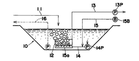
次に、上記構成の排水処理装置の運転方法を説明する。まず、図2及び図3は、原水の流入量が、この排水処理装置の計画水量のときの運転方法を示すもので、間欠的に曝気処理を行って嫌気好気法により下排水の処理を行う例を示している。
【0012】
処理槽10には、原水流入経路11から所定量の原水が流入しており、処理水循環経路14のポンプ14Pが作動して処理槽10内の処理水を循環させて槽内の処理水を撹拌するとともに、処理水排出経路13のポンプ13Pが作動して処理槽10内の処理水を膜分離装置12から排出している。そして、図2に示す曝気経路15による曝気運転(好気運転)と、図3に示す非曝気運転(嫌気運転)とが交互に行われる。すなわち、曝気経路15のブロワー15Bを所定間隔で間欠的に作動させることにより、下排水の好気処理と嫌気処理とを交互に行うようにしている。この運転方法(間欠曝気法)は、好気運転と嫌気運転との時間の割振りを適当に設定することにより、窒素除去率を向上させることができ、高度の浄水処理を行うことができる。
【0013】
また、好気運転と嫌気運転とを交互に行うことにより、好気運転時の曝気処理で膜分離装置12の付着物(ケーキ層)を除去することができ、長期間にわたって安定した運転を行うことができる。
【0014】
なお、膜分離装置12からの処理水の吸引排出は、間欠的に行うことが望ましく、運転時間中に1/5〜1/10程度の時間割合で停止させることが好ましい。さらに、膜の透過流速は、通常、1日あたり0.24〜0.4mの範囲に設定することが好ましい。
【0015】
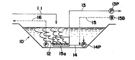
図4は、計画水量よりも水量が少ないときの運転状態例を示すもので、処理槽10内の処理水を、処理水排出経路13から所定量抜き取った状態で上述の間欠曝気法を行い、流入原水の処理を行いながら、ポンプ16Pを作動させて槽底部に濃縮された状態の汚泥を汚泥導出経路16から抜き取るようにしている。これにより、余剰汚泥を濃縮した状態で抜き取ることができるので、汚泥の処理を容易に行うことができる。
【0016】
また、膜分離装置12においては、膜の性能を保証するために、適当な時期に膜を薬液で洗浄する必要があるが、例えば、図4に示した低水量時の運転方法で運転しているときに容易に行うことができる。
【0017】
すなわち、図5に示すように、前述の図4に示す低水量時の運転において、複数ユニット設けられている膜分離装置12の中の1ユニットを水面上に引上げ、該膜分離装置12内に薬液調整槽31内の薬液を、経路32,ポンプ32Pを介して注入し、所定時間、例えば約1時間放置して膜の洗浄を行う。その後、この膜分離装置12を処理水中に戻して処理水の排出を開始すればよい。
【0018】
本形態例に示すように、この排水処理装置は、固液分離を膜分離装置で行うので沈殿池を設ける必要がないことから、維持管理が容易であるだけでなく、施工や撤去を迅速に行うことができ、移設も容易に行うことができる。また、膜分離装置と曝気装置とをユニット化することにより、施工や撤去を迅速に行うことができる。
【0019】
さらに、高濃度MLSSにより汚泥発生量の低減が図れ、間欠曝気法により窒素の除去も行うことができる。しかも、膜の洗浄も、現地で簡単な操作で行うことができ、原水流入量に応じた自動化も可能である。加えて、余剰汚泥を引抜く際に膜を介して処理水をある程度抜き取ってから行うことにより、余剰汚泥の減容化が図れ、後処理装置として紫外線殺菌装置を使用することにより、安全で高度な処理水質を得ることができる。
【0020】
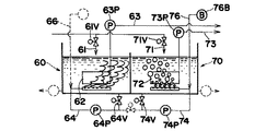
また、本発明では、上述のような処理槽を複数設置することもできる。例えば、図6は、処理水槽51内をオーバーフロー堰52で区画して第一処理槽60と第二処理槽70とを形成したもので、各処理槽60,70には、原水を流入させる第一流入経路61及び第二流入経路71と、各処理槽60,70内の処理水をそれぞれ膜分離装置62,72を介して排出する第一排水経路63及び第二排水経路73と、各処理槽60,70内の処理水を導出して各処理槽60,70内に循環させることにより処理水を撹拌する第一循環経路64及び第二循環経路74と、この第一循環経路64及び第二循環経路74の経路を利用して一方の処理槽内の処理水を他方の処理槽内に導入する第一導入経路65と、前記オーバーフロー堰52により形成される第二導入経路75と、各処理槽60,70内に曝気空気を導入する第一曝気経路66及び第二曝気経路76と、各処理槽60,70内の汚泥を導出する第一汚泥経路67及び第二汚泥経路77とがそれぞれ設けられている。
【0021】
第一流入経路61及び第二流入経路71は、原水流入路1に設けたスクリーン2の下流で分岐しており、第一排水経路63及び第二排水経路73は、紫外線殺菌装置等の後処理装置3の入口部で合流している。さらに、第一汚泥経路67及び第二汚泥経路77は、汚泥貯留槽4の入口部で合流しており、汚泥貯留槽4内の余剰汚泥は、汚泥処理設備5で脱水処理してコンテナ6aに移送し、前記スクリーン2からのし渣も、し渣処理器7で処理してコンテナ6bに移送するように形成している。また、各経路の必要個所には、それぞれポンプ(P)や弁が設けられ、両曝気経路66,76には、ブロワー(B)がそれぞれ設けられている。なお、両曝気経路66,76の噴出部やその設置位置は、前記同様に形成されているので詳細な説明は省略する。
【0022】
このような2槽式の装置においては、図7に示すように、前記図2及び図3と同様の間欠曝気法による運転方法を行うことができる。
【0023】
すなわち、第一処理槽60及び第二処理槽70には、それぞれ第一流入経路61及び第二流入経路71から所定量の原水を流入させ、第一循環経路64及び第二循環経路74により各処理槽60,70内の処理水を各処理層内に循環させて撹拌するとともに、第一排水経路63及び第二排水経路73から各処理槽内の処理水を膜分離装置62,27を介して排出する。そして、第一曝気経路66及び第二曝気経路76による曝気運転は、両処理槽60,70についてそれぞれ間欠的に行うようにしている。
【0024】
なお、図7においては、処理槽60が嫌気運転中、処理槽70が好気運転中の状態を表しており、第一,第二流入経路61,71の弁61V,71V及び第一,第二循環経路64,74の弁64V,74Vがそれぞれ開、第一,第二排水経路63,73のポンプ63P,73P及び第一,第二循環経路64,74のポンプ64P,74Pがそれぞれ作動中であって、第一,第二曝気経路66,76においては、第二曝気経路76のブロワー76Bが作動中である。
【0025】
このように両処理槽60,70について、それぞれ別個に嫌気運転と好気運転とを行って間欠曝気法により処理することにより、前記同様に高度の浄水処理を行うことができる。なお、両処理槽60,70が同時に嫌気運転あるいは好気運転を行うようにしてもよい。
【0026】
図8は、上記運転状態において水量が少ないときの運転状態例を示すもので、第一処理槽60と第二処理槽70とのいずれか一方で前記間欠曝気法による排水処理を行い、他方の処理槽を待機状態とするものである。
【0027】
例えば、第一処理槽60を待機状態にする場合は、第二処理槽70において、第二流入経路71から原水を流入させるとともに、第二循環経路74により槽内の処理水を循環させながら第二曝気経路76による曝気を間欠的に行い、膜分離装置72を介して第二排水経路73から第二処理槽70内の処理水を排出する前述の間欠曝気法による排水処理を行う。
【0028】
そして、第一処理槽60では、膜分離装置62を介して第一排水経路63から第一処理槽60内の処理水をある程度排出して汚泥を濃縮した後、第一汚泥経路67のポンプ67Pを作動させて槽内の余剰汚泥の引抜きを行ったり、膜分離装置62の洗浄等の保守作業を行うようにする。
【0029】
図9は、計画水量時における他の運転方法を示すもので、一方の処理槽、例えば第一処理槽60で嫌気運転を行い、他方の処理槽である第二処理槽70で好気運転を行うとともに、該第二処理槽70内の処理水の一部を第一処理槽60に循環させる循環法による排水処理を行う例を示している。
【0030】
まず、嫌気運転を行っている第一処理槽60には、第一流入経路61から所定量の原水を流入させるとともに、第二処理槽70から弁74Vを介して導出した処理水の一部をポンプ64Pにより第一導入経路65,弁65V及び第一循環経路64を介して循環流入させる。同時に、第一処理槽60内の処理水は、膜分離装置62からポンプ63P,第一排水経路63を介して排出されている。
【0031】
また、好気運転を行っている第二処理槽70には、第一処理槽60の処理水がオーバーフロー堰52(第二導入経路75)をオーバーフローして流入しており、第二処理槽70内の処理水は、前述のように、その一部が第一導入経路65及び第一循環経路64を介して第一処理槽60に循環するとともに、残部がポンプ74Pにより第二循環経路74を通って第二処理槽70に循環して槽内を撹拌している。同時に、第二曝気経路76のブロワー76Bによる曝気処理が行われるとともに、処理水を膜分離装置72を介して第二排水経路73,ポンプ73Pから排出している。
【0032】
このような循環法による排水処理は、窒素除去率は、第二処理槽70から第一処理槽60への処理水の循環率によって決まるため、ある程度以上の除去率を望むことはできないが、循環率を適当に設定するだけの簡単な操作で安定した運転を行うことができる。
【0033】
そして、第一処理槽60での嫌気運転と第二処理槽70での好気運転とを、適当な期間、例えば1日毎に切換えて運転することにより、好気運転時の曝気処理で膜分離装置62,72の付着物(ケーキ層)を除去することができる。
【0034】
したがって、前記図7に示す間欠曝気法と、この循環法とは、管理レベルによって選択することが可能であり、ある程度の窒素除去率で安定した運転状態を望むならば循環法を、高度の窒素除去を必要とする場合は、前記間欠曝気法を採用すればよい。
【0035】
【発明の効果】
以上説明したように、本発明の排水処理装置の運転方法によれば、簡単な装置構成で高度の排水処理が可能であり、施工や撤去も迅速に行うことができる。
【図面の簡単な説明】
【図1】本発明の排水処理装置の一例を示す系統図である。
【図2】計画水量時における好気運転の状態を示す説明図である。
【図3】同じく嫌気運転の状態を示す説明図である。
【図4】低水量時における運転状態を示す説明図である。
【図5】膜分離装置の洗浄時の状態を示す説明図である。
【図6】2槽式とした排水処理装置の一例を示す系統図である。
【図7】2槽式排水処理装置における計画水量時の運転状態の一例を示す説明図である。
【図8】同じく低水量時の運転状態を示す説明図である。
【図9】2槽式排水処理装置における他の運転状態を示す説明図である。
【符号の説明】
1…原水流入路、2…スクリーン、3…後処理装置、4…汚泥貯留槽、5…汚泥処理設備、7…し渣処理器、10…処理槽、11…原水流入経路、12…膜分離装置、13…処理水排出経路、14…処理水循環経路、15…曝気経路、16…汚泥導出経路、60,70…第一,第二処理槽[0001]
TECHNICAL FIELD OF THE INVENTION
The present invention relates to a method of operating a waste water treatment equipment, particularly, a method for the operation of waste water treatment equipment by possible membrane separation method relocation optionally relatively small.
[0002]
Problems to be solved by the prior art and the invention
Solid-liquid separation methods used in conventional wastewater treatment facilities are mainly gravity sedimentation methods, and it has been difficult to reduce the size of the facilities. Although a simple structure such as an unearthed pond that is relatively easy to install and remove is also known, relocation requires a considerable period of time and cost.
[0003]
On the other hand, the membrane separation method, which has been rapidly commercialized in recent years in the fields of sewage, human waste, and water purification, can perform solid-liquid separation in a relatively compact facility as compared with the gravity sedimentation method, and can save labor. is there. However, it has been difficult to say that the conventional wastewater treatment facilities that use the membrane separation method still make full use of the advantages of the membrane separation method.
[0004]
The present invention is to fully utilize the advantages of membrane separation method, with miniaturized, and its object is to provide a wastewater treatment equipment operating method capable to cope with the relocation.
[0005]
[Means for Solving the Problems]
In order to achieve the above object, a method of operating a wastewater treatment apparatus according to the present invention is directed to a wastewater treatment method in which raw water flows into a treatment tank for purifying sewage and the treated water in the treatment tank is discharged through a membrane separation device. In the operation method of the apparatus, when the inflow amount of raw water is the planned water amount of the wastewater treatment apparatus, a predetermined amount of raw water flows into the treatment tank from the raw water inflow path, and the treated water in the treatment tank is stirred by the treated water stirring means. When the treated water in the treatment tank is discharged from the treated water discharge path through the membrane separation device and the aeration operation by the aeration path is performed at predetermined intervals, and when the inflow amount of the raw water is smaller than the planned water amount, It is characterized in that excess sludge is extracted from the sludge discharge route .
[0006]
Further, another operation method of the wastewater treatment apparatus of the present invention is an operation method of a wastewater treatment apparatus in which raw water flows into a treatment tank for purifying sewage and the treated water in the treatment tank is discharged through a membrane separation device. In the method, the treatment tank is divided into a first treatment tank and a second treatment tank, and when the inflow of raw water is the planned water amount of the wastewater treatment apparatus, a predetermined amount of raw water flows into both treatment tanks from the raw water inflow path. while stirring the treated water in each processing tank respectively by the first and second treated water stirring means, discharging the first and second from the treated water discharge path via a membrane separation device in each processing tank treated water, respectively The aeration operation by the first and second aeration paths is performed at predetermined intervals, and when the inflow of raw water is smaller than the planned water amount, the aeration operation is performed in one of the first processing tank and the second processing tank. performed at intervals, the other one of the processing tank It is characterized by pulling excess sludge from the sludge outlet path. Further, in the operation at the time of low water flow where the inflow of raw water is smaller than the planned water flow in both of the above operation methods, one of the membrane separation devices provided in the processing tank is pulled up on the water surface, and the pulled-up membrane is pulled up. The membrane can be washed by injecting the chemical in the chemical adjustment tank into the separation device .
[0007]
BEST MODE FOR CARRYING OUT THE INVENTION
Hereinafter, the present invention will be described in more detail with reference to the drawings. FIG. 1 is a system diagram showing an example of a wastewater treatment apparatus according to the present invention. FIGS. 2 to 4 are explanatory diagrams of operation methods, respectively, and FIG. 5 is an explanatory diagram showing an example of a cleaning operation of a membrane separation device.
[0008]
First, as shown in FIG. 1, the wastewater treatment apparatus according to the present embodiment includes a raw water inflow path 11 through which raw water flows into a
[0009]
The raw water inflow path 11 is connected to the raw water inflow path 1 via the screen 2, and the treated
[0010]
Further, the jetting portion 15a in the
[0011]
Next, an operation method of the wastewater treatment apparatus having the above configuration will be described. First, FIG. 2 and FIG. 3 show the operation method when the inflow of raw water is the planned amount of water in the wastewater treatment apparatus. The wastewater is treated intermittently by aerating and aerobically aerobic. An example is shown.
[0012]
A predetermined amount of raw water flows into the
[0013]
Further, by alternately performing the aerobic operation and the anaerobic operation, it is possible to remove deposits (cake layer) on the
[0014]
The suction and discharge of the treatment water from the
[0015]
FIG. 4 shows an example of an operation state when the amount of water is smaller than the planned amount of water. The above-described intermittent aeration method is performed in a state where a predetermined amount of the treated water in the
[0016]
Further, in the
[0017]
That is, as shown in FIG. 5, in the operation at the time of the low water amount shown in FIG. 4 described above, one unit of the
[0018]
As shown in the present embodiment, the wastewater treatment device does not require a sedimentation tank because solid-liquid separation is performed by a membrane separation device, so not only maintenance and management is easy, but also construction and removal can be performed quickly. The transfer can be easily performed. Further, by unitizing the membrane separation device and the aeration device, construction and removal can be performed quickly.
[0019]
Furthermore, the sludge generation amount can be reduced by the high concentration MLSS, and nitrogen can be removed by the intermittent aeration method. In addition, membrane cleaning can be performed on the spot with simple operations, and automation according to the amount of raw water inflow is also possible. In addition, the volume of excess sludge can be reduced by extracting the treated water to a certain extent through a membrane when extracting excess sludge, and by using an ultraviolet sterilizer as a post-treatment device, it is safe and sophisticated. The quality of treated water can be obtained.
[0020]
Further, in the present invention, a plurality of processing tanks as described above may be provided. For example, FIG. 6 shows a case where the inside of the treatment water tank 51 is partitioned by an overflow weir 52 to form a
[0021]
The first inflow path 61 and the
[0022]
In such a two-tank type apparatus, as shown in FIG. 7, an operation method based on the intermittent aeration method similar to FIGS. 2 and 3 can be performed.
[0023]
That is, a predetermined amount of raw water flows into the
[0024]
Note that FIG. 7 shows a state in which the
[0025]
As described above, by performing the anaerobic operation and the aerobic operation separately for the two
[0026]
FIG. 8 shows an example of an operation state when the amount of water is small in the above operation state. In one of the
[0027]
For example, when the
[0028]
Then, in the
[0029]
FIG. 9 shows another operation method at the time of the planned water volume. An anaerobic operation is performed in one processing tank, for example, the
[0030]
First, a predetermined amount of raw water flows from the first inflow path 61 into the
[0031]
Further, the treated water in the
[0032]
In such wastewater treatment by the circulation method, since the nitrogen removal rate is determined by the circulation rate of the treated water from the
[0033]
The anaerobic operation in the
[0034]
Therefore, the intermittent aeration method shown in FIG. 7 and this circulation method can be selected depending on the management level. If a stable operation state with a certain nitrogen removal rate is desired, the circulation method should be performed at a high nitrogen level. When removal is necessary, the above-mentioned intermittent aeration method may be adopted.
[0035]
【The invention's effect】
As described above, according to the waste water treatment equipment operating method of the present invention, is capable of a high degree of wastewater treatment with a simple apparatus configuration can be carried out construction and removal quickly.
[Brief description of the drawings]
FIG. 1 is a system diagram showing an example of a wastewater treatment device of the present invention.
FIG. 2 is an explanatory diagram showing a state of aerobic operation at a planned water volume.
FIG. 3 is an explanatory diagram showing a state of anaerobic driving.
FIG. 4 is an explanatory diagram showing an operation state when the amount of water is low.
FIG. 5 is an explanatory diagram showing a state of the membrane separation device during cleaning.
FIG. 6 is a system diagram showing an example of a two-tank type wastewater treatment apparatus.
FIG. 7 is an explanatory diagram showing an example of an operation state of the two-tank type wastewater treatment apparatus at a planned water volume.
FIG. 8 is an explanatory diagram showing an operation state when the amount of water is low.
FIG. 9 is an explanatory diagram showing another operation state of the two-tank type wastewater treatment apparatus.
[Explanation of symbols]
DESCRIPTION OF SYMBOLS 1 ... Raw water inflow path, 2 ... Screen, 3 ... Post-processing device, 4 ... Sludge storage tank, 5 ... Sludge treatment equipment, 7 ... Slag treatment equipment, 10 ... Treatment tank, 11 ... Raw water inflow path, 12 ... Membrane separation Apparatus, 13: treated water discharge path, 14: treated water circulation path, 15: aeration path, 16: sludge derivation path, 60, 70: first and second treatment tanks
Claims (3)
Priority Applications (1)
| Application Number | Priority Date | Filing Date | Title |
|---|---|---|---|
| JP31338996A JP3600947B2 (en) | 1996-11-25 | 1996-11-25 | Operating method of wastewater treatment equipment |
Applications Claiming Priority (1)
| Application Number | Priority Date | Filing Date | Title |
|---|---|---|---|
| JP31338996A JP3600947B2 (en) | 1996-11-25 | 1996-11-25 | Operating method of wastewater treatment equipment |
Related Child Applications (2)
| Application Number | Title | Priority Date | Filing Date |
|---|---|---|---|
| JP2004145998A Division JP3754977B2 (en) | 2004-05-17 | 2004-05-17 | Waste water treatment apparatus and operation method thereof |
| JP2004145997A Division JP2004268040A (en) | 2004-05-17 | 2004-05-17 | Waste water treatment apparatus and operation method therefor |
Publications (2)
| Publication Number | Publication Date |
|---|---|
| JPH10151480A JPH10151480A (en) | 1998-06-09 |
| JP3600947B2 true JP3600947B2 (en) | 2004-12-15 |
Family
ID=18040689
Family Applications (1)
| Application Number | Title | Priority Date | Filing Date |
|---|---|---|---|
| JP31338996A Expired - Fee Related JP3600947B2 (en) | 1996-11-25 | 1996-11-25 | Operating method of wastewater treatment equipment |
Country Status (1)
| Country | Link |
|---|---|
| JP (1) | JP3600947B2 (en) |
Families Citing this family (9)
| Publication number | Priority date | Publication date | Assignee | Title |
|---|---|---|---|---|
| JP4046445B2 (en) * | 1999-08-26 | 2008-02-13 | 株式会社クボタ | Wastewater treatment method |
| JP2001062481A (en) * | 1999-08-26 | 2001-03-13 | Kubota Corp | Treatment of concentrated sewage |
| CN1143725C (en) * | 1999-11-18 | 2004-03-31 | 齐侬环境有限公司 | Immersed membrane element and module |
| US7264727B2 (en) * | 2003-01-25 | 2007-09-04 | Holt Karl K | Septic system remediation method and apparatus |
| US7468135B2 (en) | 2003-01-25 | 2008-12-23 | Engineered Solutions, Inc. | Portable tank wastewater treatment system and method |
| CA2609005C (en) | 2005-05-19 | 2012-10-23 | Karl K. Holt | Improved septic system remediation method and apparatus |
| JP5194151B2 (en) * | 2011-07-20 | 2013-05-08 | 前澤工業株式会社 | Waste water treatment equipment |
| CN103112950A (en) * | 2013-03-08 | 2013-05-22 | 厦门大学 | Dynamic-membrane anaerobic-aerobic integrated online backwash treatment method for printing and dyeing wastewater |
| CN103721569B (en) * | 2014-01-03 | 2017-03-08 | 成都大学 | A kind of Ultra-filtration device for rural domestic wastewater |
Family Cites Families (7)
| Publication number | Priority date | Publication date | Assignee | Title |
|---|---|---|---|---|
| JPS55127192A (en) * | 1979-03-22 | 1980-10-01 | Toshiba Corp | Operating of sewage treating apparatus by activated soludge method |
| JP2727189B2 (en) * | 1987-10-31 | 1998-03-11 | 株式会社鶴見製作所 | Adjustment method of sludge concentration in sewage treatment tank |
| JPH05185092A (en) * | 1992-01-10 | 1993-07-27 | Kubota Corp | Waste water disposing device |
| JPH06335694A (en) * | 1993-05-31 | 1994-12-06 | Meidensha Corp | Controller of device for biologically treating waste water |
| JP3493051B2 (en) * | 1993-12-28 | 2004-02-03 | ヤンマー株式会社 | Batch type wastewater treatment equipment and activated sludge concentration measurement equipment |
| JPH07241596A (en) * | 1994-03-01 | 1995-09-19 | Sumitomo Heavy Ind Ltd | Treatment of waste water |
| JP4269345B2 (en) * | 1995-07-27 | 2009-05-27 | 栗田工業株式会社 | Wastewater treatment equipment |
-
1996
- 1996-11-25 JP JP31338996A patent/JP3600947B2/en not_active Expired - Fee Related
Also Published As
| Publication number | Publication date |
|---|---|
| JPH10151480A (en) | 1998-06-09 |
Similar Documents
| Publication | Publication Date | Title |
|---|---|---|
| CN104876360B (en) | Rainwater purification apparatus based on ceramic membrane | |
| JP7110052B2 (en) | Method for operating organic wastewater treatment equipment and organic wastewater treatment equipment | |
| JP3600947B2 (en) | Operating method of wastewater treatment equipment | |
| HU227187B1 (en) | Method for biological effluent treatment | |
| KR100489728B1 (en) | Wastewater treatment system by multiple sequencing batch reactor and its operation methods | |
| JP6181003B2 (en) | Membrane separation activated sludge treatment apparatus and operation method thereof | |
| JPH0461998A (en) | Discharged water treatment device | |
| JP4082556B2 (en) | Nitrogen removal equipment in membrane separation type oxidation ditch | |
| CN110461777A (en) | Method for processing organic wastewater and organic waste-water treating apparatus | |
| PL186772B1 (en) | Sewage treating process | |
| JP3714749B2 (en) | Operation method of waste water treatment equipment | |
| JPS63166499A (en) | Apparatus for biological denitrification/ dephosphorization treatment of sewage | |
| JP2004321908A (en) | Sewage treatment apparatus and sewage treatment method | |
| JP2002166139A (en) | Membrane separator | |
| JP3754977B2 (en) | Waste water treatment apparatus and operation method thereof | |
| KR100566320B1 (en) | Submerged membrane coupled advanced wastewater treatment method and its system | |
| JP2004268040A (en) | Waste water treatment apparatus and operation method therefor | |
| JP2007275895A (en) | Method for removing nitrogen in membrane separation type oxidation ditch and device therefor | |
| JP3785212B2 (en) | Wastewater treatment equipment | |
| JP2003205297A (en) | Waste water treating system | |
| JP3408699B2 (en) | Sewage treatment equipment using immersion type membrane separation equipment | |
| JP7195968B2 (en) | Method for operating organic wastewater treatment equipment and organic wastewater treatment equipment | |
| JPH11216490A (en) | Organic waste water treating device | |
| JPS6125439B2 (en) | ||
| JP2744381B2 (en) | Water treatment control device |
Legal Events
| Date | Code | Title | Description |
|---|---|---|---|
| A977 | Report on retrieval |
Free format text: JAPANESE INTERMEDIATE CODE: A971007 Effective date: 20040126 |
|
| A131 | Notification of reasons for refusal |
Free format text: JAPANESE INTERMEDIATE CODE: A131 Effective date: 20040316 |
|
| A521 | Written amendment |
Free format text: JAPANESE INTERMEDIATE CODE: A523 Effective date: 20040517 |
|
| TRDD | Decision of grant or rejection written | ||
| A01 | Written decision to grant a patent or to grant a registration (utility model) |
Free format text: JAPANESE INTERMEDIATE CODE: A01 Effective date: 20040817 |
|
| A61 | First payment of annual fees (during grant procedure) |
Free format text: JAPANESE INTERMEDIATE CODE: A61 Effective date: 20040907 |
|
| R150 | Certificate of patent or registration of utility model |
Free format text: JAPANESE INTERMEDIATE CODE: R150 |
|
| FPAY | Renewal fee payment (event date is renewal date of database) |
Free format text: PAYMENT UNTIL: 20081001 Year of fee payment: 4 |
|
| FPAY | Renewal fee payment (event date is renewal date of database) |
Free format text: PAYMENT UNTIL: 20091001 Year of fee payment: 5 |
|
| FPAY | Renewal fee payment (event date is renewal date of database) |
Free format text: PAYMENT UNTIL: 20091001 Year of fee payment: 5 |
|
| S531 | Written request for registration of change of domicile |
Free format text: JAPANESE INTERMEDIATE CODE: R313531 |
|
| FPAY | Renewal fee payment (event date is renewal date of database) |
Free format text: PAYMENT UNTIL: 20091001 Year of fee payment: 5 |
|
| R360 | Written notification for declining of transfer of rights |
Free format text: JAPANESE INTERMEDIATE CODE: R360 |
|
| FPAY | Renewal fee payment (event date is renewal date of database) |
Free format text: PAYMENT UNTIL: 20091001 Year of fee payment: 5 |
|
| R360 | Written notification for declining of transfer of rights |
Free format text: JAPANESE INTERMEDIATE CODE: R360 |
|
| R371 | Transfer withdrawn |
Free format text: JAPANESE INTERMEDIATE CODE: R371 |
|
| S531 | Written request for registration of change of domicile |
Free format text: JAPANESE INTERMEDIATE CODE: R313531 |
|
| FPAY | Renewal fee payment (event date is renewal date of database) |
Free format text: PAYMENT UNTIL: 20091001 Year of fee payment: 5 |
|
| R350 | Written notification of registration of transfer |
Free format text: JAPANESE INTERMEDIATE CODE: R350 |
|
| FPAY | Renewal fee payment (event date is renewal date of database) |
Free format text: PAYMENT UNTIL: 20101001 Year of fee payment: 6 |
|
| FPAY | Renewal fee payment (event date is renewal date of database) |
Free format text: PAYMENT UNTIL: 20101001 Year of fee payment: 6 |
|
| FPAY | Renewal fee payment (event date is renewal date of database) |
Free format text: PAYMENT UNTIL: 20111001 Year of fee payment: 7 |
|
| FPAY | Renewal fee payment (event date is renewal date of database) |
Free format text: PAYMENT UNTIL: 20121001 Year of fee payment: 8 |
|
| FPAY | Renewal fee payment (event date is renewal date of database) |
Free format text: PAYMENT UNTIL: 20131001 Year of fee payment: 9 |
|
| LAPS | Cancellation because of no payment of annual fees |