JP3589802B2 - Information recording method and apparatus - Google Patents
Information recording method and apparatus Download PDFInfo
- Publication number
- JP3589802B2 JP3589802B2 JP22158796A JP22158796A JP3589802B2 JP 3589802 B2 JP3589802 B2 JP 3589802B2 JP 22158796 A JP22158796 A JP 22158796A JP 22158796 A JP22158796 A JP 22158796A JP 3589802 B2 JP3589802 B2 JP 3589802B2
- Authority
- JP
- Japan
- Prior art keywords
- recording
- information
- unit
- storage amount
- error correction
- Prior art date
- Legal status (The legal status is an assumption and is not a legal conclusion. Google has not performed a legal analysis and makes no representation as to the accuracy of the status listed.)
- Expired - Fee Related
Links
Images


Classifications
-
- G—PHYSICS
- G06—COMPUTING; CALCULATING OR COUNTING
- G06F—ELECTRIC DIGITAL DATA PROCESSING
- G06F3/00—Input arrangements for transferring data to be processed into a form capable of being handled by the computer; Output arrangements for transferring data from processing unit to output unit, e.g. interface arrangements
- G06F3/06—Digital input from, or digital output to, record carriers, e.g. RAID, emulated record carriers or networked record carriers
- G06F3/0601—Interfaces specially adapted for storage systems
- G06F3/0602—Interfaces specially adapted for storage systems specifically adapted to achieve a particular effect
- G06F3/061—Improving I/O performance
- G06F3/0613—Improving I/O performance in relation to throughput
-
- G—PHYSICS
- G06—COMPUTING; CALCULATING OR COUNTING
- G06F—ELECTRIC DIGITAL DATA PROCESSING
- G06F3/00—Input arrangements for transferring data to be processed into a form capable of being handled by the computer; Output arrangements for transferring data from processing unit to output unit, e.g. interface arrangements
- G06F3/06—Digital input from, or digital output to, record carriers, e.g. RAID, emulated record carriers or networked record carriers
- G06F3/0601—Interfaces specially adapted for storage systems
- G06F3/0628—Interfaces specially adapted for storage systems making use of a particular technique
- G06F3/0655—Vertical data movement, i.e. input-output transfer; data movement between one or more hosts and one or more storage devices
- G06F3/0656—Data buffering arrangements
-
- G—PHYSICS
- G06—COMPUTING; CALCULATING OR COUNTING
- G06F—ELECTRIC DIGITAL DATA PROCESSING
- G06F3/00—Input arrangements for transferring data to be processed into a form capable of being handled by the computer; Output arrangements for transferring data from processing unit to output unit, e.g. interface arrangements
- G06F3/06—Digital input from, or digital output to, record carriers, e.g. RAID, emulated record carriers or networked record carriers
- G06F3/0601—Interfaces specially adapted for storage systems
- G06F3/0668—Interfaces specially adapted for storage systems adopting a particular infrastructure
- G06F3/0671—In-line storage system
- G06F3/0673—Single storage device
- G06F3/0674—Disk device
- G06F3/0677—Optical disk device, e.g. CD-ROM, DVD
-
- G—PHYSICS
- G11—INFORMATION STORAGE
- G11B—INFORMATION STORAGE BASED ON RELATIVE MOVEMENT BETWEEN RECORD CARRIER AND TRANSDUCER
- G11B19/00—Driving, starting, stopping record carriers not specifically of filamentary or web form, or of supports therefor; Control thereof; Control of operating function ; Driving both disc and head
- G11B19/02—Control of operating function, e.g. switching from recording to reproducing
- G11B19/04—Arrangements for preventing, inhibiting, or warning against double recording on the same blank or against other recording or reproducing malfunctions
-
- G—PHYSICS
- G11—INFORMATION STORAGE
- G11B—INFORMATION STORAGE BASED ON RELATIVE MOVEMENT BETWEEN RECORD CARRIER AND TRANSDUCER
- G11B20/00—Signal processing not specific to the method of recording or reproducing; Circuits therefor
- G11B20/10—Digital recording or reproducing
- G11B20/10527—Audio or video recording; Data buffering arrangements
-
- G—PHYSICS
- G11—INFORMATION STORAGE
- G11B—INFORMATION STORAGE BASED ON RELATIVE MOVEMENT BETWEEN RECORD CARRIER AND TRANSDUCER
- G11B20/00—Signal processing not specific to the method of recording or reproducing; Circuits therefor
- G11B20/10—Digital recording or reproducing
- G11B20/18—Error detection or correction; Testing, e.g. of drop-outs
- G11B20/1833—Error detection or correction; Testing, e.g. of drop-outs by adding special lists or symbols to the coded information
-
- G—PHYSICS
- G11—INFORMATION STORAGE
- G11B—INFORMATION STORAGE BASED ON RELATIVE MOVEMENT BETWEEN RECORD CARRIER AND TRANSDUCER
- G11B27/00—Editing; Indexing; Addressing; Timing or synchronising; Monitoring; Measuring tape travel
- G11B27/10—Indexing; Addressing; Timing or synchronising; Measuring tape travel
- G11B27/19—Indexing; Addressing; Timing or synchronising; Measuring tape travel by using information detectable on the record carrier
- G11B27/28—Indexing; Addressing; Timing or synchronising; Measuring tape travel by using information detectable on the record carrier by using information signals recorded by the same method as the main recording
- G11B27/30—Indexing; Addressing; Timing or synchronising; Measuring tape travel by using information detectable on the record carrier by using information signals recorded by the same method as the main recording on the same track as the main recording
- G11B27/3027—Indexing; Addressing; Timing or synchronising; Measuring tape travel by using information detectable on the record carrier by using information signals recorded by the same method as the main recording on the same track as the main recording used signal is digitally coded
-
- G—PHYSICS
- G11—INFORMATION STORAGE
- G11B—INFORMATION STORAGE BASED ON RELATIVE MOVEMENT BETWEEN RECORD CARRIER AND TRANSDUCER
- G11B20/00—Signal processing not specific to the method of recording or reproducing; Circuits therefor
- G11B20/10—Digital recording or reproducing
- G11B20/12—Formatting, e.g. arrangement of data block or words on the record carriers
- G11B20/1217—Formatting, e.g. arrangement of data block or words on the record carriers on discs
-
- G—PHYSICS
- G11—INFORMATION STORAGE
- G11B—INFORMATION STORAGE BASED ON RELATIVE MOVEMENT BETWEEN RECORD CARRIER AND TRANSDUCER
- G11B20/00—Signal processing not specific to the method of recording or reproducing; Circuits therefor
- G11B20/10—Digital recording or reproducing
- G11B20/18—Error detection or correction; Testing, e.g. of drop-outs
- G11B20/1866—Error detection or correction; Testing, e.g. of drop-outs by interleaving
-
- G—PHYSICS
- G11—INFORMATION STORAGE
- G11B—INFORMATION STORAGE BASED ON RELATIVE MOVEMENT BETWEEN RECORD CARRIER AND TRANSDUCER
- G11B20/00—Signal processing not specific to the method of recording or reproducing; Circuits therefor
- G11B20/10—Digital recording or reproducing
- G11B20/10527—Audio or video recording; Data buffering arrangements
- G11B2020/1062—Data buffering arrangements, e.g. recording or playback buffers
- G11B2020/10675—Data buffering arrangements, e.g. recording or playback buffers aspects of buffer control
- G11B2020/1074—Data buffering arrangements, e.g. recording or playback buffers aspects of buffer control involving a specific threshold value
-
- G—PHYSICS
- G11—INFORMATION STORAGE
- G11B—INFORMATION STORAGE BASED ON RELATIVE MOVEMENT BETWEEN RECORD CARRIER AND TRANSDUCER
- G11B20/00—Signal processing not specific to the method of recording or reproducing; Circuits therefor
- G11B20/10—Digital recording or reproducing
- G11B20/10527—Audio or video recording; Data buffering arrangements
- G11B2020/1062—Data buffering arrangements, e.g. recording or playback buffers
- G11B2020/10814—Data buffering arrangements, e.g. recording or playback buffers involving specific measures to prevent a buffer underrun
-
- G—PHYSICS
- G11—INFORMATION STORAGE
- G11B—INFORMATION STORAGE BASED ON RELATIVE MOVEMENT BETWEEN RECORD CARRIER AND TRANSDUCER
- G11B2220/00—Record carriers by type
- G11B2220/20—Disc-shaped record carriers
- G11B2220/21—Disc-shaped record carriers characterised in that the disc is of read-only, rewritable, or recordable type
- G11B2220/215—Recordable discs
- G11B2220/218—Write-once discs
-
- G—PHYSICS
- G11—INFORMATION STORAGE
- G11B—INFORMATION STORAGE BASED ON RELATIVE MOVEMENT BETWEEN RECORD CARRIER AND TRANSDUCER
- G11B2220/00—Record carriers by type
- G11B2220/20—Disc-shaped record carriers
- G11B2220/25—Disc-shaped record carriers characterised in that the disc is based on a specific recording technology
- G11B2220/2537—Optical discs
- G11B2220/2545—CDs
- G11B2220/2554—CD-V [CD-Video], CDV, or CD+V, as defined in IEC 61104
-
- G—PHYSICS
- G11—INFORMATION STORAGE
- G11B—INFORMATION STORAGE BASED ON RELATIVE MOVEMENT BETWEEN RECORD CARRIER AND TRANSDUCER
- G11B2220/00—Record carriers by type
- G11B2220/20—Disc-shaped record carriers
- G11B2220/25—Disc-shaped record carriers characterised in that the disc is based on a specific recording technology
- G11B2220/2537—Optical discs
- G11B2220/2562—DVDs [digital versatile discs]; Digital video discs; MMCDs; HDCDs
Landscapes
- Engineering & Computer Science (AREA)
- Theoretical Computer Science (AREA)
- Human Computer Interaction (AREA)
- Physics & Mathematics (AREA)
- General Engineering & Computer Science (AREA)
- General Physics & Mathematics (AREA)
- Signal Processing (AREA)
- Multimedia (AREA)
- Signal Processing For Digital Recording And Reproducing (AREA)
- Optical Recording Or Reproduction (AREA)
Description
【0001】
【発明の属する技術分野】
本発明は、ホストコンピュータ等の外部記憶装置として利用され、一回のみ記録可能なDVD−R(DVD−Recordable)に代表される高密度光ディスク等の追記型情報記録媒体に対して情報を記録するための情報記録方法及び装置の技術分野に属する。
【0002】
【従来の技術】
一般に、この種の情報記録装置は、ホストコンピュータから入力された種々のデータを、当該ホストコンピュータの制御に基づいて一回のみ記録可能に追記型情報記録媒体(以下、DVD−R等という。)に記録する動作を実行する。このとき、ホストコンピュータから情報記録装置に転送されるデータの転送速度と当該転送されたデータを情報記録装置がDVD−R等に記録する記録速度とは異なることが多く、通常は、上記ホストコンピュータからの転送速度の方が速くなるように設定されている。
【0003】
そこで、上記転送速度と記録速度の速度差を相殺する方法として、上記情報記録装置にバッファメモリを設け、転送されてきたデータを当該転送速度で一時的にバッファメモリ内に記憶し、これを記録速度に対応した速度で読み出すことにより速度差を相殺する方法が一般的に行われている。
【0004】
ところで、上記バッファメモリを備える情報記録装置においては、上記転送速度と記録速度との速度差に起因して、バッファメモリから読み出すデータ量とバッファメモリに書込むデータ量とのバランスが崩れ、バッファメモリから読み出すデータ量よりもバッファメモリに書込むデータ量の方が多くなり、バッファメモリ内のデータの記憶量が連続的に増加してしまう状況が生じ得る。このため、情報記録装置を制御するプロセッサは、転送されてきた一区分のデータの記憶が終了すると、データの転送を一時的に中止すべき旨のコマンド(以下、データ転送停止コマンドという。)をホストコンピュータに送信すると共にDVD−R等への記録に伴って増加するバッファメモリ内の空き記録領域の容量を常に監視し、当該空き容量が所定のレベル以上となったときに次の一区切りのデータのホストコンピュータからの転送を要求するコマンド(以下、データ転送要求コマンドという。)をホストコンピュータに送信する。そして、新しいデータが転送されると共にバッファメモリ内に蓄積され、当該バッファメモリの空き容量が「0」又は所定のレベル以下となったとき、再度データ転送停止コマンドをホストコンピュータに送信する。以上の動作が繰返されることにより、転送されたデータがDVD−R等に記録されることとなる。そして、ホストコンピュータは、上記データ転送停止コマンド及びデータ転送要求コマンドに基づいてデータの転送制御を行うのである。
【0005】
ところで、上記ホストコンピュータには、上記情報記録装置に以外にも、ハードディスクドライブ等の種々の周辺装置が接続されている場合が一般的であるが、これらの周辺装置の動作速度は、ホストコンピュータの演算速度に比して遅い場合が多い。このため、ホストコンピュータが一の周辺装置に対しての処理を行い、当該処理が終了した後に他の処理に移行する、いわゆるバッチ処理においては、ホストコンピュータの利用効率の向上を目的として、ホストコンピュータにおいて各周辺装置毎の処理に対して優先順位を設け、当該優先順位に基づいて時分割的に各周辺装置毎の処理を行うことが一般的である。
【0006】
このとき、当該優先順位においては、ホストコンピュータの使用者に直接関わる、いわゆるマン−マシーンインターフェースに関わるものほど優先順位が高く設定されるのが通常であるので、ホストコンピュータは上記情報記録装置からのデータ転送要求コマンドを受信しても、当該情報記録装置より高い優先順位を有する他の周辺装置に対する処理を実行中においては、当該データ転送要求コマンドに直ちに応答することができない場合が生じる。つまり、情報記録装置はデータのDVD−R等への記録動作を実行しているにも拘らず、バッファメモリには記録すべきデータが蓄えられていない状態、すなわち、いわゆる情報記録装置におけるアンダーランの状態が生じる場合があるのである。
【0007】
このアンダーランの状態が生じると、バッファメモリからのデータの読み出しにおいて当該データの連続性が保てなくなるが、この場合、従来のDVD−R等に対する情報記録装置においては、記録動作を一時的に中断し、アンダーランが解消された後に、データの所定の区切り毎に、既に記録が完了しているデータを含む新たなデータを当該DVD−R等上の新たな記録領域に記録し直すことが行われている。
【0008】
【発明が解決しようとする課題】
しかしながら、DVD−R等を用いた情報記録装置においては、一度記録したデータは消去することができないので、アンダーランが発生したときにデータが記録されていたDVD−R等上の記録領域は、データの連続性のない無効領域となり、当該DVD−R等を再生する際には読み飛ばされることとなる。従って、当該無効領域は、大量のデータを記録する必要のあるDVD−R等においては極めて不効率であり、DVD−R等の記録領域を有効に活用できないという問題点がある。
【0009】
また、連続性が保たれていないデータがそのままDVD−R等上に存在すると、再生時に誤動作になる場合があるという問題点もある。
そこで、本発明は、上記の問題点に鑑みて成されたもので、その課題は、アンダーランが生じた場合でも、DVD−R等の記録領域を無駄にすることがなく、且つ再生時に正確に再生することができるようにデータを記録することが可能な情報記録方法及び装置を提供することにある。
【0010】
上記の課題を解決するために,請求項1に記載の発明は、記録情報を一時的にバッファ手段に記憶するバッファ工程と、前記バッファ手段より前記記録情報を読み出して所定の信号処理を施し、複数の誤り訂正単位からなる処理記録情報を生成する処理記録情報生成工程と、当該処理記録情報を情報記録媒体に記録する記録工程と、前記バッファ手段における前記記録情報の記憶量を検出する検出工程と、前記検出された記憶量が第1の所定記憶量未満となったとき、前記誤り訂正単位内の所定位置において前記処理記録情報の記録を停止する停止工程と、前記検出された記憶量が第2の所定記憶量以上となったとき、前記停止工程において記録が停止された前記誤り訂正単位の先頭を除く当該記録が停止された誤り訂正単位内のいずれかの位置から前記情報記録媒体への記録を再開する記録再開工程と、を含む。
【0011】
上記の課題を解決するために、請求項11に記載の発明は、記録情報を一時的に記憶するバッファ手段と、前記バッファ手段より前記記録情報を読み出して所定の信号処理を施し、複数の誤り訂正単位からなる処理記録情報を生成する処理記録情報生成手段と、当該処理記録情報を情報記録媒体に記録する記録手段と、前記バッファ手段における前記記録情報の記憶量を検出する検出手段と、前記検出された記憶量が第1の所定記憶量未満となったとき、前記誤り訂正単位内の所定位置において前記処理記録情報の記録を停止する停止手段と、前記検出された記憶量が第2の所定記憶量以上となったとき、前記停止手段により記録が停止された前記誤り訂正単位の先頭を除く当該記録が停止された誤り訂正単位内のいずれかの位置から前記情報記録媒体への記録を再開する記録再開手段と、を備える。
上記の課題を解決するために、請求項21に記載の発明は、記録情報に所定の信号処理を施し、複数の誤り訂正単位からなる処理記録情報を生成する処理記録情報生成工程と、前記処理記録情報をバッファ手段に記憶するバッファ工程と、前記バッファ手段より読み出された前記処理記録情報を情報記録媒体に記録する記録工程と、前記バッファ手段における前記処理記録情報の記憶量を検出する検出工程と、前記検出された記憶量が第1の所定記憶量未満となったとき、前記誤り訂正単位内の所定位置において前記処理記録情報の記録を停止する停止工程と、前記検出された記憶量が第2の所定記憶量以上となったとき、前記停止工程において記録が停止された前記誤り訂正単位の先頭を除く当該誤り訂正単位内の位置から前記情報記録媒体への記録を再開する記録再開工程と、を含む。
上記の課題を解決するために、請求項31に記載の発明は、記録情報に所定の信号処理を施し、複数の誤り訂正単位からなる処理記録情報を生成する処理記録情報生成手段と、前記処理記録情報を記憶するバッファ手段と、前記バッファ手段より読み出された前記処理記録情報を情報記録媒体に記録する記録手段と、前記バッファ手段における前記処理記録情報の記憶量を検出する検出手段と、前記検出された記憶量が第1の所定記憶量未満となったとき、前記誤り訂正単位内の所定位置において前記処理記録情報の記録を停止する停止手段と、前記検出された記憶量が第2の所定記憶量以上となったとき、前記停止手段により記録が停止された前記誤り訂正単位の先頭を除く当該誤り訂正単位内の位置から前記情報記録媒体への記録を再開する記録再開手段と、を備える。
【0038】
【発明の実施の形態】
次に、本発明に好適な実施の形態について、図面に基づいて説明する。なお、以下の実施形態は、上記DVD−Rに対して情報を記録するための情報記録装置について本発明を適用した実施の形態を説明するものである。
(I)記録フォーマットの実施の形態
始めに、DVD−Rに記録情報を記録する際の一般的な物理フォーマット及び当該記録情報における誤り訂正処理について、図1及び図2を用いて説明する。
【0039】
先ず、本実施の形態のDVD−Rにおける誤り訂正処理及び当該誤り訂正処理における誤り訂正単位としてのECCブロックについて、図1を用いて説明する。
【0040】
一般に、DVD−Rに記録される記録情報は、図1(a)に示すデータセクタ20を複数個含む物理構造を成して構成されている。そして、一のデータセクタ20中には、その先頭から、データセクタ20の開始位置を示すID情報21と、当該ID情報21の誤りを訂正するためのID情報誤り訂正コード(IEC(ID Data Error correction Code ))22と、予備データ23と、記録すべき主たるデータであるデータ24と、データ24におけるエラーを検出するためのエラー検出コード(EDC(Error Detection Code))25とにより構成され、このデータセクタ20が複数連続することにより記録すべき記録情報が構成されている。
【0041】
次に、このデータセクタ20を用いてECCブロックを構成する際の後述のエンコーダにおける処理を、図1(b)を用いて説明する。
データセクタ20を用いてECCブロックを構成する際には、図1(b)に示すように、始めに、一のデータセクタ20を172バイト毎に分割し、分割した夫々のデータ(これを、以下、データブロック33という。)を垂直方向に並べる(図1(b)−1参照)。このとき、垂直方向には12行のデータブロック33が並ぶこととなる。
【0042】
そして、垂直方向に並べた夫々のデータブロック33に対して10バイトのECC内符号(PI(Pality In )符号)31を当該データブロック33の最後に付加して一の訂正ブロック34を構成する(図1(b)−2参照)。この段階では、ECC内符号31が付加された訂正ブロック34が垂直方向に12行並んでいることとなる。その後、以上の処理を16のデータセクタ20分だけ繰返す。これにより、192行の訂正ブロック34が得られる。
【0043】
次に、上記の192行の訂正ブロック34が垂直方向に並べられた状態で、今度は、当該192行の訂正ブロック34を1バイト毎に最初から垂直方向に分割し、分割した夫々のデータに対して16個のECC外符号(PO(Pality Out)符号)32を付加する。なお、当該ECC外符号32は、上記訂正ブロック34のうち、ECC内符号31の部分に対しても付加される。
【0044】
以上の処理により、16のデータセクタ20を含む一のECCブロック30が図1(b)−2に示すように形成される。このとき、一のECCブロック30内に含まれる情報の総量は、
(172+10)バイト×(192+16)行=37856バイト
であり、この内、実際のデータ24は、
2048バイト×16=32768バイト
となる。
【0045】
また、図1(b)−2に示すECCブロック30においては、1バイトのデータを「D#.*」で示している。例えば、「D1.0」は第1行第0列に配置されている1バイトのデータを示しており、「D190.170」は第190行第170列に配置されている1バイトのデータを示している。従って、ECC内符号31は第172列乃至第181列に配置され、ECC外符号32は第192行乃至第207行に配置されることとなる。
【0046】
更に、一の訂正ブロック34はDVD−R上には連続して記録される。
ここで、図1(b)−2に示すように、ECCブロック30をECC内符号31とECC外符号32の双方を含むように構成するのは、図1(b)−2における水平方向に並んでいるデータの訂正をECC内符号31で行い、図1(b)−2における垂直方向に並んでいるデータの訂正をECC外符号32で行うためである。すなわち、図1(b)−2で示すECCブロック30内においては、水平方向と垂直方向の二重に誤り訂正することが可能となる。
【0047】
この点についてより具体的には、例えば、一の訂正ブロック34(上述のように、一行分のECC内符号31を含んで計182バイトのデータを含み、連続してDVD−R上に記録される。)が全てDVD−Rのキズ等により破壊されたとしても、それを垂直方向から見ると、1列のECC外符号32に対して1バイトのデータ破壊でしかない。従って、夫々の列のECC外符号32を用いて誤り訂正を行えば、たとえ一の訂正ブロック34の全てが破壊されていても、正しく誤り訂正を行って正確に再生することができるのである。
【0048】
次に、図1(b)−2で示すECCブロック30に構成されたデータセクタ20が、具体的にDVD−Rにどのように記録されるかについて、図2を用いて説明する。なお、図2において、「D#.*」で示されるデータは、図1(b)−2内に記述されている各データに対応している。なお、図2のうち、データセクタ20を記録する際の処理(インターリーブ及び8−16変調)については、後述のエンコーダにおいて実行される処理である。
【0049】
ECCブロック30をDVD−Rに記録する際には、始めに、図2最上段に示すように、ECCブロック30が訂正ブロック34毎に水平方向に一列に並べられてインターリーブされることにより、16のレコーディングセクタ40に分割される。このとき、一のレコーディングセクタ40は、2366バイト(37856バイト÷16)の情報を含むこととなり、この中には、データセクタ20とECC内符号31又はECC外符号32が混在している。但し、各レコーディングセクタ40の先頭には、データセクタ20におけるID情報21(図1(a)参照)が配置される。
【0050】
そして、一のレコーディングセクタ40は、91バイト毎のデータ41に分割され、夫々にヘッダHが付加される。その後、この状態のレコーディングセクタ40を8−16変調することにより、夫々のデータ41毎に一のシンクフレーム42が形成される。このとき、一のシンクフレーム42はヘッダH’とデータ43とにより構成されている。また、一のシンクフレーム42内の情報量は、
91バイト×8×(16/8)=1456バイト
となり、このシンクフレーム42が連続した形態でDVD−R1に情報が書き込まれる。このとき、一のレコーディングセクタ40は、26のシンクフレーム42を含むこととなる。
【0051】
以上説明した物理フォーマットを構成してDVD−Rに情報を記録することにより、当該情報を再生する際に8−16復調及びデインターリーブを行えば(図2参照)、もとのECCブロック30を復元することができ、上記のように強力な誤り訂正を行って情報を正確に再生することができるのである。
(II)情報記録装置の実施の形態
次に、図1及び図2を用いて説明した物理フォーマットで、情報をDVD−R1に記録するための本発明に係る情報記録装置の実施の形態について、図3乃至図5を用いて説明する。なお、以下の実施の形態では、DVD−R1において、当該DVD−R1上のアドレス情報等を記録したプリピットが、記録情報を記録すべき情報トラック上等に予め形成されており、記録情報の記録時には、当該プリピットを予め検出することによりDVD−R1上のアドレス情報を得、これにより記録情報を記録するDVD−R1上の記録位置を検出して記録するものとする。
【0052】
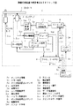
始めに、本発明に係る情報記録装置の構成について、図3を用いて説明する。
図3に示すように、実施形態の情報記録装置Sは、記録再開手段としてのピックアップ2と、再生増幅器3と、デコーダ4と、プリピット信号デコーダ5と、スピンドルモータ6と、サーボ回路7と、検出手段、停止手段、記憶手段及び記録再開手段としてのプロセッサ8と、記録再開手段としてのエンコーダ9と、パワー制御回路11と、レーザ駆動回路12と、インターフェース13とにより構成されている。また、当該情報記録装置Sには、外部のホストコンピュータ14から記録すべき記録情報SR がインターフェース13を介して入力されている。
【0053】
また、エンコーダ9は、バッファ手段としてのバッファメモリ10を備えている。
次に、全体の動作を説明する。
【0054】
ピックアップ2は、図示しないレーザダイオード、偏向ビームスプリッタ、対物レンズ、光検出器等を含み、レーザ駆動信号SDLに基づいて光ビームBをDVD−R1の情報記録面に照射し、その反射光に基づいて上記プリピットを検出して記録すべき後述のエンコード信号SRE記録すると共に、既に記録されている情報がある場合には、上記光ビームBの反射光に基づいて当該既に記録されている情報を検出する。
【0055】
そして、再生増幅器3は、ピックアップ2から出力されたプリピットに対応する情報を含む検出信号SDTを増幅し、プリピットに対応するプリピット信号SPPを出力すると共に、既に記録されている記録情報に対応する増幅信号SP を出力する。
【0056】
その後、デコーダ4は、増幅信号SP に対して8−16復調及びデインターリーブを施すことにより当該増幅信号SP をデコードし、復調信号SDM及びサーボ復調信号SSDを出力する。
【0057】
一方、プリピット信号デコーダ5は、プリピット信号SPPをデコードして復調プリピット信号SPDを出力する。
そして、サーボ回路7は、復調プリピット信号SPD及びサーボ復調信号SSDに基づいて、ピックアップ2におけるフォーカスサーボ制御及びトラッキングサーボ制御のためのピックアップサーボ信号SSPを出力すると共に、DVD−R1を回転させるためのスピンドルモータ6の回転をサーボ制御するためのスピンドルサーボ信号SSSを出力する。
【0058】
これらと並行して、プロセッサ8は、復調信号SDMに基づいて既に記録されていた情報に対応する再生信号SOTを外部に出力すると共に、バッファ制御信号SC を出力して後述の本発明に係る記録動作を主として制御する。
【0059】
一方、インターフェース13は、プロセッサ8の制御の下、ホストコンピュータ14から送信されてくる記録情報SR に対して、これを情報記録装置Sに取り込むためのインターフェース動作を行い、当該記録情報SR をエンコーダ9に出力する。
【0060】
そして、エンコーダ9は、図示しないECCジェネレータ、8−16変調部、スクランブラ等及びバッファメモリ10を含み、記録情報SR に対してECC内符号31及びECC外符号32を付加してECCブロック30を構成すると共に、当該ECCブロック30に対してインターリーブ及び8−16変調並びにスクランブル処理を施し、エンコード信号SREを生成する。このとき、エンコーダ9に含まれるバッファメモリ10は、プロセッサ8からのバッファ制御信号SC に基づいて、ホストコンピュータ14からの記録情報SR を一時的に記憶し、DVD−R1に対するピックアップ2によるエンコード信号SREの記録速度に対応した読み出し速度で当該記録情報SR を出力する。
【0061】
そして、パワー制御回路11は、エンコード信号SREに基づいて、ピックアップ2内の図示しないレーザダイオードの出力を制御するための駆動信号SD を出力する。
【0062】
その後、レーザ駆動回路12は、駆動信号SD に基づいて、実際に上記レーザダイオードを駆動して光ビームBを出射させるためのレーザ駆動信号SDLを出力する。
【0063】
なお、上記の情報記録装置Sは、DVD−R1に記録されている情報を再生することも可能であり、その際には、復調信号SDMに基づいてプロセッサ8を介して再生信号SOTが外部に出力されることとなる。
(III )情報記録動作
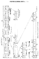
次に、本発明に係る記録情報の記録動作について図4及び図5を用いて説明する。なお、図4は、本発明に係る記録情報の記録動作を示すフローチャートであり、主としてプロセッサ8において実行される処理を示すフローチャートである。また、図5(a)は、図4に示す記録動作を実行する際のバッファメモリ10内の記録情報SR のデータ量を示すものであり、図5(b)は、図4に示す記録動作に対応するデータの変化を示す図である。
【0064】
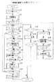
図4に示すように、本発明に係る記録動作においては、始めに、情報記録装置Sが起動されると、インターフェース13を介してホストコンピュータ14から記録情報SR が取り込まれ、エンコーダ9内のバッファメモリ10に蓄積される(ステップS1、図5(a)符号(ア)部参照)。そして、バッファメモリ10が満たされると、ホストコンピュータ14に対して上記データ転送停止コマンドSS を送信すると共に、バッファメモリ10に記憶されている記録情報SR に基づいてエンコード信号SREを生成し、パワー制御回路11、レーザ駆動回路12及びピックアップ2等により当該エンコード信号SREの記録が開始され(ステップS2)、次に、バッファメモリ10がアンダーラン状態になったことを示すプロセッサ8内のURフラグを初期化する(ステップS3)。このとき、ステップS2において記録が開始されると、バッファメモリ10内のデータ量は逐次減少して行くこととなる(図5(a)符号(イ)部参照)。
【0065】
次に、記録情報SR の出力が継続される過程でバッファメモリ10内のデータ量がプロセッサ8により確認され(ステップS4)、その後、URフラグが「1」であり(URフラグが「1」のときは、バッファメモリ10がアンダーラン状態であることを示している。)、且つ、バッファメモリ10内のデータ量がフル(バッファメモリ10が記録情報SR で満たされている。)でないか否かがプロセッサ8により判定される。
【0066】
ステップS5においては、現在は、URフラグは「1」ではないので(ステップS5;NO)、次に、バッファメモリ10内のデータ量がホストコンピュータ14に対して上記のデータ転送要求コマンドSQ を出力すべき予め設定されたバッファメモリ10のデータ量であるレベルA(図5(a)参照)より多いか否かが判定される(ステップS6)。そして、当該データ量がレベルA以下である場合には(ステップS6;NO、図5(a)符号(ウ)部参照)、プロセッサ8からデータ転送要求コマンドSQ をホストコンピュータ14に送信する(ステップS7)。これにより、ホストコンピュータ14から記録情報SR が転送されると、バッファメモリ10内のデータ量は逐次増加していく(図5(a)符号(エ)部参照)。
【0067】
この段階で、ホストコンピュータ14からの記録情報SR の転送が停止すると、記録動作は引続き継続されているので、バッファメモリ10内のデータ量は減少することとなる(図5(a)符号(オ)部参照)。すると、次にバッファメモリ10内のデータ量が予め設定された当該バッファメモリ10がアンダーランであると判断すべき基準のデータ量であるレベルB(図5(a)参照)より多いか否かが判定される(ステップS8)。ここで、より具体的には、ECCブロック30を32Kバイトで構成する場合には、レベルBは、例えば、48Kバイトとされる。
ステップS8の判定において、ホストコンピュータ14から引き続き記録情報SR が送信されず、バッファメモリ10のデータ量がレベルB以下である場合には(ステップS8;NO)、バッファメモリ10がアンダーラン状態であるとして(図5(b)参照)、次に、ピックアップ2が現在DVD−R1上にデータを記録している記録位置がDVD−R1上のどの位置であるかを確認する(ステップS9)。そして、当該記録位置がDVD−R1への記録を一時中断すべき所定の位置であるか否かが判定される(ステップS10)。本実施形態では、アンダーランの場合に記録を中断する所定の位置は、ECCブロック30の先頭から2番目のシンクフレーム42の後半部分とされる場合を示すので、この場合には、当該記録位置がECCブロック30の先頭から2番目のシンクフレーム42の後半部分にあるか否かがステップS10において判定される。そして、当該所定の位置であった場合には(ステップS10;YES)、次に、ECCブロック30の先頭から2番目のシンクフレーム42の後半部分で記録を一時中断すると共に当該2番目のシンクフレーム42を示すヘッダH’をプロセッサ8内の図示しないRAM(Random Access Memory)に記憶し、プロセッサ8内の図示しないタイマをスタートさせ、更にURフラグを「1」とする(ステップS11)。
【0068】
ここで、ステップS11の処理を実行するときのバッファメモリ10について、図5(b)を用いて説明すると、図5(b)上から2段目において、点(C)までバッファメモリ10に記録情報SR が記録されているとき当該バッファメモリ10がアンダーランとなったことを検出したとすると(ステップS8;NO)、プロセッサ8は、ピックアップ2等を制御して、図5(b)上から2段目における点(B)(ECCブロック30の先頭から2番目のシンクフレーム42の後半部分)までのエンコード信号SREを記録した状態で記録動作を一時的に中断する(ステップS11)。このとき、DVD−R1上においては、図5(b)最下段に示すように、点(B)に対応する位置まで記録が行われていることとなる。また、バッファメモリ10には、ECCブロック30の先頭から2番目のシンクフレーム42の前半の位置(例えば、図5(b)上から2段目における点(A))から図5(b)上から2段目における点(C)までに相当する記録情報SR が記憶されている。
【0069】
そして、記録が一時中断されると(ステップS11)、次に、ステップS11でスタートしているタイマがホストコンピュータ14がハングアップ状態(ホストコンピュータ14内のCPU等の支障により、記録情報SR を送信することができないトラブル状態)であるか否かを判断する基準時間Cとなったか否かが判定され(ステップS12)、なっていない場合には(ステップS12;NO)、ホストコンピュータ14からの記録情報SR の転送が再開された可能性があるとしてステップS4に戻り、バッファメモリ10内のデータ量を確認する。次に、依然としてホストコンピュータ14からの記録情報SR の転送が再開されていないときには、ステップS5は「YES」となるので、ステップS12に移行して再びタイマの値を確認する。そして、タイマが値Cになるまでホストコンピュータ14からの記録情報SR の転送が再開されない場合には(ステップS12;YES)、ホストコンピュータ14がハングアップしている可能性が高いとして、ホストコンピュータ14に対してハングアップの可能性が高いことを示すエラー信号SE を出力し(ステップS13)、処理を終了する。
【0070】
一方、一度バッファメモリ10がアンダーランとなった後に、タイマが値Cとなる前にホストコンピュータ14からの記録情報SR の転送が再開され、バッファメモリ10が満たされた場合には(図5(a)符号(カ)部参照)、ステップS5の判定においては「NO」となるので、次にステップS6においてバッファメモリ10内のデータ量がレベルAより多いか否かが判定され、現在ではバッファメモリ10は満たされているので(ステップS6;YES)、次に、ステップS14においてURフラグが「1」であるか否かが判定され、バッファメモリ10が一度アンダーラン状態となった後にデータ量が回復したときにはURフラグは「1」となっているので(ステップS14;YES)、URフラグを初期化し(ステップS17)、次に、記録を再開するに当たって、上記プロセッサ8内の図示しないRAMに記憶されている記録を中断したシンクフレーム42(ECCブロック30の先頭から2番目のシンクフレーム42)のヘッダH’を読み出す共に、記録を中断した位置(図5(b)点(B))に対応して、当該中断した位置を含むRAMから読み出したシンクフレーム42の先頭から記録を再開すべく、上述のピックアップ2の記録位置がECCブロック30の先頭から2番目のシンクフレーム42の先頭位置である接続位置にあるか否かが判定され(ステップS18)、接続位置にある場合には(ステップS18;YES)そのまま記録を再開し(ステップS20)、記録位置と接続位置が異なっている場合には(ステップS18;NO)、ピックアップ2の位置を当該シンクフレーム42の先頭位置(接続位置)まで移動して(ステップS19)、記録を再開する(ステップS20、図5(a)符号(キ)部参照))。
【0071】
このとき、ステップS20における記録の再開に当たっては、記録の中断時にバッファメモリ10に残っている記録情報SR (図5(b)上から2段目における点(A)から点(C)に相当する記録情報SR が記憶されている。)に対して、ホストコンピュータ14から転送が再開された後の記録情報SR が継ぎ足されて一連の記録情報SR とされ、当該一連の記録情報SR に対応するエンコード信号SREが、ECCブロック30の先頭から2番目のシンクフレーム42の先頭から再度記録される(図5(b)上から3段目参照)。このとき、DVD−R1上においては、図5(b)最下段に示すように、ECCブロック30の先頭から2番目のシンクフレーム42の先頭から点(B)に対応する位置までは、エンコード信号SREが重ね書きされることとなり、この部分(図5(b)最下段におけるデータ破壊領域D)ではデータが破壊されることとなるが、当該データ破壊領域Dとなるのは、一のシンクフレーム42内の領域であるので、上述の記録された情報を再生する際のエラー訂正の可能範囲内となり、再生時に誤再生されるようなことはない。
【0072】
ステップS20において、記録が再開されると、再びバッファメモリ10内のデータ量を確認してアンダーランに備えるべくステップS4に戻る。
また、ステップS6の判定においてバッファメモリ10のデータ量がレベルA以下であっても(ステップS6;NO)その後のデータ転送要求コマンドSQ (ステップS7)に対するホストコンピュータ14からの記録情報SR の転送により、データ量がレベルBより多くなった場合には(ステップS8;YES)、再度記録を実行すべくステップS14に移行する。
【0073】
更に、ステップS10における判定において、バッファメモリ10がアンダーランであるにも拘らず、ピックアップ2における記録位置が所定の位置(ECCブロック30の先頭から2番目のシンクフレーム42の後半部分)でないときには(ステップS10;NO)、記録位置が当該所定の位置となるまで記録を続行すべくステップS14に移行する。
【0074】
一方、ステップS14において、それまでアンダーランが生じていないか、または生じていても解消されている場合には、URフラグは「1」ではないので(ステップS14;NO)、その場合には引続きエンコード信号SREの記録を継続し(ステップS15)、次に、ホストコンピュータ14からの記録情報SR の終了コマンド等により記録情報SR の転送が全て終了したか否かが判定され(ステップS16)、終了している場合には(ステップS16;YES)記録処理を終了し、記録情報SR の転送が終了していない場合には(ステップS16;NO)、継続して記録動作を行うと共にバッファメモリ10内のデータ量を確認してアンダーランに備えるべくステップS4に戻る。
【0075】
なお、図4に示すフローチャートにおいて、アンダーランが生じない通常の場合には、ステップS1、S2、S3、S4、S5、S6(又はS8)、S14、S15及びS16の処理が繰返されることとなる。
【0076】
以上説明したように、実施形態の記録動作によれば、バッファメモリ10内のデータ量が所定のレベルB未満となったとき、ECCブロック30の先頭から2番目のシンクフレーム42内の後半部分において記録を一時的に停止し、当該データ量がレベルB(又はレベルA)以上に回復したとき当該ECCブロック30の先頭から2番目のシンクフレーム42の先頭から記録を再開するので、記録情報SRにアンダーランが生じてバッファメモリ10内のデータ量が低下しても、DVD−R1に記録後のエンコード信号SREを再生する際に、連続性を確保することができ、正確な再生が可能となる。
従って、正確且つ確実に記録情報S R の記録再生が可能となる。
【0077】
また、ECCブロック30の先頭から2番目のシンクフレーム42の先頭から記録を再開するので、DVD−R1上では記録情報SR (エンコード信号SRE)が連続して記録できることとなり、DVD−R1における記録領域を無駄にすることがない。
【0078】
更に、エンコード信号SREが重ねて記録される範囲が一のシンクフレーム42内のみであるので、再生時に誤り訂正するのが容易となる。
また、記録情報SR がホストコンピュータ14から出力されてくるので、当該ホストコンピュータ14における支障により記録情報SR が途切れ、これによりエンコード信号SREの生成が中断しても、DVD−R1上ではエンコード信号SREを連続的に記録することができる。
【0079】
更にまた、プロセッサ8が、エンコード信号SREの記録を停止した後、バッファメモリ10におけるデータ量がレベルB未満のままであるとき、ホストコンピュータ14に対してエラー信号SE を送信するので、当該ホストコンピュータ14に対してエラー状態であることを認識させることができる。
【0080】
なお、上記の実施形態においては、ECCブロック30の先頭から2番目のシンクフレーム42内で記録を中断し、当該シンクフレーム42の先頭から記録を再開したが、これに限らず、ECCブロック30の再生時のエラー訂正能力の範囲内であれば、記録を中断したシンクフレーム42より複数シンクフレーム分前のシンクフレームから重ね書きして記録を再開するようにしてもよい。この場合に、記録を中断したときに記録中であったシンクフレーム42をプロセッサ8に記憶しておき、記録の再開時に当該記憶しておいたシンクフレーム42を基準に複数シンクフレーム分前のシンクフレーム42又は当該記憶しておいたシンクフレーム42自体から重ね書きして記録を再開するようにすれば、ECCブロック30の再生時のエラー訂正能力の範囲内の任意のシンクフレーム42において記録を中断することができる。
【0081】
更に、上記の実施の形態においては、記録情報SR を一時的にバッファメモリ10に記憶した後に読み出して、ECCブロック30の生成及びインターリーブ等を行うようにした情報記録装置Sに対して本発明を適用した場合について説明したが、これに限らず、記録情報SR に対してECCブロック30の生成及びインターリーブ等を施した後にバッファメモリ10に一時的に記憶した後DVD−R1に記録する構成を備える情報記録装置に対して本発明を適用することも可能である。この場合には、当該バッファメモリ10にはエンコード信号SREが記憶されることとなる。
【0082】
また、上記の実施形態においては、DVD−R1に情報を記録する場合について説明したが、これに限らず、シンクフレーム等の記録単位に分割されている情報を記録する場合であれば、本発明は、ハードディスク装置又はフレキシブルディスク装置等に対して広く適用することが可能である。
【図面の簡単な説明】
【図1】実施形態の記録情報におけるECCブロックの構造を示す図であり、(a)は記録情報のデータ構造を示す図であり、(b)はECCブロックの構成を示す図である。
【図2】実施形態の記録情報の物理フォーマットを示す図である。
【図3】情報記録装置の概要構成を示すブロック図である。
【図4】情報記録動作の処理を示すフローチャートである。
【図5】情報記録動作中のバッファメモリ及びデータの状態を示す図であり、(a)はバッファメモリ内のデータ量の推移を示す図であり、(b)は記録動作中のデータの状態を示す図である。
【符号の説明】
1…DVD−R
2…ピックアップ
3…再生増幅器
4…デコーダ
5…プリピット信号デコーダ
6…スピンドルモータ
7…サーボ回路
8…プロセッサ
9…エンコーダ
10…バッファメモリ
11…パワー制御回路
12…レーザ駆動回路
20…データセクタ
21…ID情報
22…ID情報誤り訂正コード
23…予備データ
24、41、43…データ
25…エラー検出コード
30…ECCブロック
31…ECC内符号
32…ECC外符号
33…データブロック
34…訂正ブロック
40…レコーディングセクタ
42…シンクフレーム
B…光ビーム
H、H’…ヘッダ
D…データ破壊領域
SR …記録情報
SE …エラー信号
SQ …データ転送要求コマンド
SS …データ転送停止コマンド
SC …バッファ制御信号
SRE…エンコード信号
SD …駆動信号
SDL…レーザ駆動信号
SDT…検出信号
SOT…再生信号
SP …増幅信号
SPP…プリピット信号
SDM…復調信号
SSD…サーボ復調信号
SPD…復調プリピット信号
SSP…ピックアップサーボ信号
SSS…スピンドルサーボ信号[0001]
TECHNICAL FIELD OF THE INVENTION
INDUSTRIAL APPLICABILITY The present invention is used as an external storage device of a host computer or the like, and records information on a write-once information recording medium such as a high-density optical disk represented by a DVD-R (DVD-Recordable) that can be recorded only once. The technical field of information recording method and apparatus for the same.
[0002]
[Prior art]
Generally, this type of information recording device is capable of recording various data input from a host computer only once under the control of the host computer, and is a write-once information recording medium (hereinafter referred to as DVD-R or the like). Execute the operation to be recorded in. At this time, the transfer speed of data transferred from the host computer to the information recording device often differs from the recording speed at which the information recording device records the transferred data on a DVD-R or the like. The transfer speed from is set to be faster.
[0003]
Therefore, as a method for canceling the speed difference between the transfer speed and the recording speed, a buffer memory is provided in the information recording device, and the transferred data is temporarily stored in the buffer memory at the transfer speed, and is recorded. A method of canceling the speed difference by reading at a speed corresponding to the speed is generally performed.
[0004]
By the way, in the information recording apparatus having the buffer memory, the balance between the amount of data read from the buffer memory and the amount of data to be written into the buffer memory is lost due to the speed difference between the transfer speed and the recording speed. The amount of data written to the buffer memory is larger than the amount of data read from the buffer memory, and a situation may occur in which the amount of data stored in the buffer memory continuously increases. For this reason, the processor that controls the information recording device issues a command (hereinafter referred to as a data transfer stop command) indicating that the transfer of the data should be temporarily stopped when the storage of the transferred one section of data is completed. The capacity of the free recording area in the buffer memory, which is transmitted to the host computer and increases along with the recording on the DVD-R or the like, is constantly monitored. A command requesting transfer from the host computer (hereinafter, referred to as a data transfer request command) is transmitted to the host computer. Then, the new data is transferred and accumulated in the buffer memory, and when the free space of the buffer memory becomes “0” or a predetermined level or less, a data transfer stop command is transmitted to the host computer again. By repeating the above operation, the transferred data is recorded on the DVD-R or the like. Then, the host computer controls the data transfer based on the data transfer stop command and the data transfer request command.
[0005]
By the way, in general, various peripheral devices such as a hard disk drive are connected to the host computer in addition to the information recording device. However, the operating speed of these peripheral devices depends on the host computer. It is often slower than the calculation speed. For this reason, in a so-called batch process in which the host computer performs a process on one peripheral device and shifts to another process after the completion of the process, the host computer aims to improve the use efficiency of the host computer. It is common practice to assign priorities to the processes for each peripheral device and to perform the processes for each peripheral device in a time-sharing manner based on the priorities.
[0006]
At this time, in the priority order, it is normal that the priority order is set higher for those directly related to the user of the host computer, that is, for the so-called man-machine interface. Even if a data transfer request command is received, it may not be possible to immediately respond to the data transfer request command while processing is being performed on another peripheral device having a higher priority than the information recording device. That is, although the information recording apparatus is executing the operation of recording data on a DVD-R or the like, no data to be recorded is stored in the buffer memory, that is, a so-called underrun in the information recording apparatus. May occur.
[0007]
When this underrun condition occurs, the continuity of the data cannot be maintained when reading the data from the buffer memory. In this case, however, in a conventional information recording apparatus for a DVD-R or the like, the recording operation is temporarily stopped. After the interruption and the underrun is resolved, it is possible to re-record new data including the already-recorded data in a new recording area on the DVD-R or the like at each predetermined data break. Is being done.
[0008]
[Problems to be solved by the invention]
However, in an information recording apparatus using a DVD-R or the like, since data once recorded cannot be erased, the recording area on the DVD-R or the like where data was recorded when an underrun occurred was This becomes an invalid area without data continuity, and is skipped when the DVD-R or the like is reproduced. Therefore, the invalid area is extremely inefficient in a DVD-R or the like that needs to record a large amount of data, and there is a problem that the recording area of the DVD-R or the like cannot be effectively used.
[0009]
Further, if data that does not maintain continuity exists on a DVD-R or the like as it is, there is a problem that a malfunction may occur during reproduction.
Therefore, the present invention has been made in view of the above-mentioned problems, and an object of the present invention is to prevent a recording area of a DVD-R or the like from being wasted even when an underrun occurs, and to provide an accurate reproduction mode. It is an object of the present invention to provide an information recording method and apparatus capable of recording data so that the data can be reproduced.
[0010]
In order to solve the above-mentioned problem, the invention according to
[0011]
In order to solve the above-mentioned problem, the invention according to
In order to solve the above-mentioned problem, the invention according to
In order to solve the above-mentioned problem, the invention according to
[0038]
BEST MODE FOR CARRYING OUT THE INVENTION
Next, a preferred embodiment of the present invention will be described with reference to the drawings. The following embodiment describes an embodiment in which the present invention is applied to an information recording apparatus for recording information on the DVD-R.
(I)Embodiment of recording format
First, a general physical format when recording information is recorded on a DVD-R and an error correction process on the recording information will be described with reference to FIGS.
[0039]
First, an error correction process in a DVD-R according to the present embodiment and an ECC block as an error correction unit in the error correction process will be described with reference to FIG.
[0040]
Generally, recording information recorded on a DVD-R has a physical structure including a plurality of
[0041]
Next, a process in an encoder described later when forming an ECC block using the
When configuring an ECC block using the
[0042]
Then, a 10-byte ECC internal code (PI (Parity In) code) 31 is added to each data block 33 arranged in the vertical direction at the end of the data block 33 to form one correction block 34 ( 1 (b) -2). At this stage, the correction blocks 34 to which the ECC
[0043]
Next, in a state where the above-mentioned 192 lines of correction blocks 34 are arranged in the vertical direction, the 192 lines of correction blocks 34 are vertically divided from the beginning for each byte, and the divided data are respectively divided. On the other hand, 16 ECC outer codes (PO (Parity Out) codes) 32 are added. The ECC
[0044]
By the above processing, one
(172 + 10) bytes × (192 + 16) rows = 37856 bytes
Where the
2048 bytes x 16 = 32768 bytes
It becomes.
[0045]
Also, in the
[0046]
Further, one
Here, as shown in FIG. 1B-2, the reason why the
[0047]
More specifically, for example, one correction block 34 (as described above, includes a total of 182 bytes of data including the ECC
[0048]
Next, how the
[0049]
When recording the ECC blocks 30 on the DVD-R, first, as shown in the uppermost part of FIG. 2, the ECC blocks 30 are arranged in a line in the horizontal direction for each
[0050]
Then, one
91 bytes x 8 x (16/8) = 1456 bytes
Thus, information is written to the DVD-R1 in a form in which the sync frames 42 are continuous. At this time, one
[0051]
By configuring the physical format described above and recording information on the DVD-R, if the information is reproduced, if the 8-16 demodulation and deinterleaving are performed (see FIG. 2), the
(II)Embodiment of information recording device
Next, an embodiment of an information recording apparatus according to the present invention for recording information on the DVD-R1 in the physical format described with reference to FIGS. 1 and 2 will be described with reference to FIGS. . In the following embodiment, in the DVD-R1, pre-pits recording address information and the like on the DVD-R1 are formed in advance on an information track where recording information is to be recorded. At times, the address information on the DVD-R1 is obtained by detecting the pre-pits in advance, and the recording position on the DVD-R1 where the recording information is to be recorded is detected and recorded.
[0052]
First, the configuration of the information recording apparatus according to the present invention will be described with reference to FIG.
As shown in FIG. 3, the information recording apparatus S of the embodiment includes a
[0053]
Further, the
Next, the overall operation will be described.
[0054]
The
[0055]
Then, the
[0056]
Thereafter, the
[0057]
On the other hand, the
Then, the
[0058]
In parallel with these, the
[0059]
On the other hand, the
[0060]
The
[0061]
Then, the
[0062]
Thereafter, the
[0063]
Note that the information recording device S can also reproduce information recorded on the DVD-R1, and in this case, the demodulated signal SDMSignal S via the
(III)Information recording operation
Next, a recording operation of recording information according to the present invention will be described with reference to FIGS. FIG. 4 is a flowchart showing a recording operation of recording information according to the present invention, and is a flowchart mainly showing processing executed by the
[0064]
As shown in FIG. 4, in the recording operation according to the present invention, first, when the information recording device S is activated, the recording information S is transmitted from the
[0065]
Next, record information SRIs continued by the
[0066]
In step S5, since the UR flag is not currently "1" (step S5; NO), the amount of data in the
[0067]
At this stage, the recording information S from the
In the determination of step S8, the recording information SRIs not transmitted and the data amount of the
[0068]
Here, the
[0069]
Then, when the recording is temporarily stopped (step S11), the timer started in step S11 causes the
[0070]
On the other hand, after the
[0071]
At this time, when resuming the recording in step S20, the recording information S remaining in the
[0072]
When recording is restarted in step S20, the amount of data in the
Further, even if the data amount of the
[0073]
Further, in the determination in step S10, when the recording position in the
[0074]
On the other hand, in step S14, if the underrun has not occurred or has occurred but has been resolved, the UR flag is not "1" (step S14; NO). Encoding signal SRE(Step S15), and then the recording information S from the
[0075]
In the flowchart shown in FIG. 4, in a normal case where underrun does not occur, the processing of steps S1, S2, S3, S4, S5, S6 (or S8), S14, S15, and S16 is repeated. .
[0076]
As described above, according to the recording operation of the embodiment, when the amount of data in the
Therefore, the recorded information S can be accurately and reliably recorded. R Can be recorded and reproduced.
[0077]
Also, since recording is restarted from the beginning of the
[0078]
Further, the encode signal SREAre recorded only in one
The record information SRIs output from the
[0079]
Furthermore, when the data amount in the
[0080]
In the above embodiment, the recording was interrupted in the
[0081]
Further, in the above embodiment, the recording information SRIs temporarily stored in the
[0082]
In the above embodiment, the case where information is recorded on the DVD-R1 has been described. However, the present invention is not limited to this, and the present invention is applicable to the case where information divided into recording units such as sync frames is recorded. Can be widely applied to hard disk devices, flexible disk devices, and the like.
[Brief description of the drawings]
FIG. 1 is a diagram showing a structure of an ECC block in recording information according to an embodiment, FIG. 1 (a) is a diagram showing a data structure of recording information, and FIG. 1 (b) is a diagram showing a configuration of an ECC block.
FIG. 2 is a diagram illustrating a physical format of recording information according to the embodiment.
FIG. 3 is a block diagram illustrating a schematic configuration of an information recording device.
FIG. 4 is a flowchart showing a process of an information recording operation.
5A and 5B are diagrams showing a state of a buffer memory and data during an information recording operation, FIG. 5A is a diagram showing a transition of a data amount in the buffer memory, and FIG. 5B is a diagram showing a state of data during a recording operation; FIG.
[Explanation of symbols]
1 ... DVD-R
2 ... Pickup
3. Regenerative amplifier
4: Decoder
5. Prepit signal decoder
6 ... Spindle motor
7 ... Servo circuit
8. Processor
9 ... Encoder
10 ... Buffer memory
11 Power control circuit
12 ... Laser drive circuit
20 ... data sector
21 ... ID information
22 ... ID information error correction code
23… Preliminary data
24, 41, 43 ... data
25 ... Error detection code
30 ... ECC block
31 ... ECC inner code
32: ECC outer code
33 Data block
34: Correction block
40 ... Recording sector
42 ... Sync frame
B: Light beam
H, H '... header
D: Data destruction area
SR… Record information
SE… Error signal
SQ… Data transfer request command
SS… Data transfer stop command
SC… Buffer control signal
SRE… Encoding signal
SD… Drive signal
SDL… Laser drive signal
SDT… Detection signal
SOT… Reproduction signal
SP… Amplified signal
SPP… Pre-pit signal
SDM... Demodulated signal
SSD... servo demodulation signal
SPD... Demodulated pre-pit signal
SSP… Pickup servo signal
SSS… Spindle servo signal
Claims (40)
前記バッファ手段より前記記録情報を読み出して所定の信号処理を施し、複数の誤り訂正単位からなる処理記録情報を生成する処理記録情報生成工程と、
当該処理記録情報を情報記録媒体に記録する記録工程と、
前記バッファ手段における前記記録情報の記憶量を検出する検出工程と、
前記検出された記憶量が第1の所定記憶量未満となったとき、前記誤り訂正単位内の所定位置において前記処理記録情報の記録を停止する停止工程と、
前記検出された記憶量が第2の所定記憶量以上となったとき、前記停止工程において記録が停止された前記誤り訂正単位の先頭を除く当該記録が停止された誤り訂正単位内のいずれかの位置から前記情報記録媒体への記録を再開する記録再開工程と、
を含むことを特徴とする情報記録方法。A buffer step of temporarily storing the record information in a buffer means;
A process record information generating step of reading the record information from the buffer unit and performing predetermined signal processing to generate process record information including a plurality of error correction units;
A recording step of recording the processing record information on an information recording medium,
A detecting step of detecting a storage amount of the recording information in the buffer means;
A stop step of stopping recording of the processing record information at a predetermined position in the error correction unit when the detected storage amount is less than a first predetermined storage amount;
When the detected storage amount is equal to or more than a second predetermined storage amount, any one of the error correction units in which the recording has been stopped except for the head of the error correction unit in which the recording has been stopped in the stopping step. A recording restart step of restarting recording on the information recording medium from a position,
An information recording method comprising:
前記記録再開工程において重ね書きされる範囲は、一個の前記記録単位内であることを特徴とする請求項2に記載の情報記録方法。Each of the error correction units includes a plurality of recording units,
3. The information recording method according to claim 2, wherein a range overwritten in the recording restarting step is within one recording unit.
前記停止工程は、停止時点における前記記録単位を記憶する記憶工程を含むと共に、
前記記録再開工程においては、前記記憶した停止時点における前記記録単位以前に記録されるべき前記処理記録情報が含まれる前記記録単位から記録を再開することを特徴とする請求項1に記載の情報記録方法。Each of the error correction units includes a plurality of recording units,
Together with the stopping step includes a storage step of storing the recording unit of the stop point,
2. The information recording apparatus according to claim 1, wherein in the recording restarting step, recording is restarted from the recording unit including the processing recording information to be recorded before the recording unit at the time of the storage stop. 3. Method.
前記記録再開工程においては、当該停止時点における前記記録単位の先頭から前記処理記録情報の前記情報記録媒体への記録を再開することを特徴とする請求項4に記載の情報記録方法。In the stopping step, of the recording units included in the error correction unit, the recording of the processing record information is stopped with the second recording unit from the beginning of the error correction unit as the recording unit at the stop point. ,
5. The information recording method according to claim 4, wherein in the recording resuming step, recording of the processing recording information on the information recording medium is resumed from a head of the recording unit at the time of the stop .
前記バッファ手段より前記記録情報を読み出して所定の信号処理を施し、複数の誤り訂正単位からなる処理記録情報を生成する処理記録情報生成手段と、
当該処理記録情報を情報記録媒体に記録する記録手段と、
前記バッファ手段における前記記録情報の記憶量を検出する検出手段と、
前記検出された記憶量が第1の所定記憶量未満となったとき、前記誤り訂正単位内の所定位置において前記処理記録情報の記録を停止する停止手段と、
前記検出された記憶量が第2の所定記憶量以上となったとき、前記停止手段により記録が停止された前記誤り訂正単位の先頭を除く当該記録が停止された誤り訂正単位内のいずれかの位置から前記情報記録媒体への記録を再開する記録再開手段と、
を備えることを特徴とする情報記録装置。Buffer means for temporarily storing recording information;
Processing record information generating means for reading the record information from the buffer means and performing predetermined signal processing to generate process record information including a plurality of error correction units;
Recording means for recording the processing record information on an information recording medium,
Detecting means for detecting the storage amount of the recording information in the buffer means;
Stopping means for stopping recording of the processing record information at a predetermined position in the error correction unit when the detected storage amount is less than a first predetermined storage amount;
When the detected storage amount becomes equal to or more than a second predetermined storage amount, any one of the error correction units in which the recording has been stopped except for the head of the error correction unit in which the recording has been stopped by the stop unit. Recording restart means for restarting recording on the information recording medium from a position,
An information recording device comprising:
前記記録再開手段により重ね書きされる範囲は、一個の前記記録単位内であることを特徴とする請求項12に記載の情報記録装置。Each of the error correction units includes a plurality of recording units,
13. The information recording apparatus according to claim 12, wherein a range overwritten by the recording restart unit is within one recording unit.
前記停止手段は、停止時点における前記記録単位を記憶する記憶手段を備えると共に、
前記記録再開手段は、前記記憶した停止時点における前記記録単位以前に記録されるべき前記処理記録情報が含まれる前記記録単位から記録を再開することを特徴とする請求項11に記載の情報記録装置。Each of the error correction units includes a plurality of recording units,
It said stop means is provided with a storage means for storing the recording unit of the stop point,
12. The information recording apparatus according to claim 11, wherein the recording resuming unit resumes recording from the recording unit including the processing recording information to be recorded before the recording unit at the time of the stored stop. .
前記記録再開手段は、当該停止時点における前記記録単位の先頭から前記処理記録情報の前記情報記録媒体への記録を再開することを特徴とする請求項14に記載の情報記録装置。The stopping unit, among the recording units included in the error correction unit, stops recording the processing record information as the recording unit at the stop point, the second recording unit from the beginning of the error correction unit,
15. The information recording apparatus according to claim 14, wherein the recording resuming unit resumes recording the processing recording information on the information recording medium from the beginning of the recording unit at the time of the stop .
前記処理記録情報をバッファ手段に記憶するバッファ工程と、A buffer step of storing the processing record information in a buffer means,
前記バッファ手段より読み出された前記処理記録情報を情報記録媒体に記録する記録工程と、A recording step of recording the processing recording information read from the buffer means on an information recording medium,
前記バッファ手段における前記処理記録情報の記憶量を検出する検出工程と、A detecting step of detecting a storage amount of the processing record information in the buffer means;
前記検出された記憶量が第1の所定記憶量未満となったとき、前記誤り訂正単位内の所定位置において前記処理記録情報の記録を停止する停止工程と、A stop step of stopping recording of the processing record information at a predetermined position in the error correction unit when the detected storage amount is less than a first predetermined storage amount;
前記検出された記憶量が第2の所定記憶量以上となったとき、前記停止工程において記録が停止された前記誤り訂正単位の先頭を除く当該誤り訂正単位内の位置から前記情報記録媒体への記録を再開する記録再開工程と、When the detected storage amount is equal to or greater than a second predetermined storage amount, the information from the position in the error correction unit to the information recording medium excluding the head of the error correction unit, the recording of which has been stopped in the stopping step, is performed. A recording resuming step of resuming recording;
を含むことを特徴とする情報記録方法。An information recording method comprising:
前記記録再開工程において重ね書きされる範囲は、一の前記記録単位内であることを特徴とする請求項22に記載の情報記録方法。 23. The information recording method according to claim 22, wherein a range overwritten in the recording restart step is within one recording unit.
前記停止工程は、停止時点における前記記録単位を記憶する記憶工程を含むと共に、The stopping step includes a storing step of storing the recording unit at the time of stopping,
前記記録再開工程においては、前記記憶した停止時点における前記記録単位以前に記録されるべき前記処理記録情報が含まれる前記記録単位から記録を再開することを特徴とする請求項21に記載の情報記録方法。22. The information recording according to claim 21, wherein, in the recording restart step, recording is restarted from the recording unit including the processing recording information to be recorded before the recording unit at the time of the stored stop. Method.
前記記録再開工程においては、当該停止時点における前記記録単位の先頭から前記処理記録情報の前記情報記録媒体への記録を再開することを特徴とする請求項24に記載の情報記録方法。25. The information recording method according to claim 24, wherein in the recording resuming step, recording of the processing recording information on the information recording medium is resumed from a head of the recording unit at the time of the stop.
前記処理記録情報を記憶するバッファ手段と、Buffer means for storing the processing record information;
前記バッファ手段より読み出された前記処理記録情報を情報記録媒体に記録する記録手段と、Recording means for recording the processing record information read from the buffer means on an information recording medium,
前記バッファ手段における前記処理記録情報の記憶量を検出する検出手段と、Detecting means for detecting a storage amount of the processing record information in the buffer means;
前記検出された記憶量が第1の所定記憶量未満となったとき、前記誤り訂正単位内の所定位置において前記処理記録情報の記録を停止する停止手段と、Stopping means for stopping recording of the processing record information at a predetermined position in the error correction unit when the detected storage amount is less than a first predetermined storage amount;
前記検出された記憶量が第2の所定記憶量以上となったとき、前記停止手段により記録が停止された前記誤り訂正単位の先頭を除く当該誤り訂正単位内の位置から前記情報記録媒体への記録を再開する記録再開手段と、When the detected storage amount is equal to or greater than a second predetermined storage amount, the information from the position in the error correction unit to the information recording medium excluding the head of the error correction unit, the recording of which has been stopped by the stop means, Recording restart means for restarting recording;
を備えることを特徴とする情報記録装置。An information recording device comprising:
前記記録再開手段により重ね書きされる範囲は、一の前記記録単位内であることを特徴とする請求項32に記載の情報記録装置。 33. The information recording apparatus according to claim 32, wherein a range overwritten by the recording restart unit is within one recording unit.
前記停止手段は、停止時点における前記記録単位を記憶する記憶手段を備えると共に、The stop unit includes a storage unit that stores the recording unit at the time of stop,
前記記録再開手段は、前記記憶した停止時点における前記記録単位以前に記録されるべき前記処理記録情報が含まれる前記記録単位から記録を再開することを特徴とする請求項31に記載の情報記録装置。32. The information recording apparatus according to claim 31, wherein the recording restart unit restarts recording from the recording unit including the processing record information to be recorded before the recording unit at the time of the stored stop. .
前記記録再開手段は、当該停止時点における前記記録単位の先頭から前記処理記録情報の前記情報記録媒体への記録を再開することを特徴とする請求項34に記載の情報記録装35. The information recording apparatus according to claim 34, wherein the recording restart unit restarts recording of the processing recording information on the information recording medium from the beginning of the recording unit at the time of the stop. 置。Place.
Priority Applications (18)
| Application Number | Priority Date | Filing Date | Title |
|---|---|---|---|
| JP22158796A JP3589802B2 (en) | 1996-08-22 | 1996-08-22 | Information recording method and apparatus |
| US08/915,649 US5815472A (en) | 1996-08-22 | 1997-08-20 | Information recording method and apparatus |
| DE69734494T DE69734494T2 (en) | 1996-08-22 | 1997-08-21 | Information recording method and apparatus |
| EP97306387A EP0825602B1 (en) | 1996-08-22 | 1997-08-21 | Information recording method and apparatus |
| EP02016852A EP1271510A3 (en) | 1996-08-22 | 1997-08-21 | information recording method and apparatus |
| EP02016851A EP1262977A3 (en) | 1996-08-22 | 1997-08-21 | Information recording method and apparatus |
| EP02016854A EP1262974A3 (en) | 1996-08-22 | 1997-08-21 | Information recording method and apparatus |
| EP02016850A EP1262972A3 (en) | 1996-08-22 | 1997-08-21 | Information recording method and apparatus |
| EP02016853A EP1262973A3 (en) | 1996-08-22 | 1997-08-21 | Information recording method and apparatus |
| CNB971193045A CN1150519C (en) | 1996-08-22 | 1997-08-22 | Information recording method and apparatus |
| CNA2006101018370A CN1975900A (en) | 1996-08-22 | 1997-08-22 | Information recording method and apparatus |
| CNB2004100322425A CN1327426C (en) | 1996-08-22 | 1997-08-22 | Information recording method and apparatus |
| CN2006101007003A CN1909091B (en) | 1996-08-22 | 1997-08-22 | Information recording method and apparatus |
| CNA2006101018652A CN1909092A (en) | 1996-08-22 | 1997-08-22 | Information recording method and apparatus |
| CNA2006101018667A CN1909093A (en) | 1996-08-22 | 1997-08-22 | Information recording method and apparatus |
| JP2000100021A JP3817111B2 (en) | 1996-08-22 | 2000-03-31 | Information recording apparatus and information recording method |
| JP2000100022A JP2000298924A (en) | 1996-08-22 | 2000-03-31 | Information recording device and information recording method |
| JP2000097548A JP3352660B2 (en) | 1996-08-22 | 2000-03-31 | Information recording apparatus and information recording method |
Applications Claiming Priority (1)
| Application Number | Priority Date | Filing Date | Title |
|---|---|---|---|
| JP22158796A JP3589802B2 (en) | 1996-08-22 | 1996-08-22 | Information recording method and apparatus |
Related Child Applications (6)
| Application Number | Title | Priority Date | Filing Date |
|---|---|---|---|
| JP2000100022A Division JP2000298924A (en) | 1996-08-22 | 2000-03-31 | Information recording device and information recording method |
| JP2000100021A Division JP3817111B2 (en) | 1996-08-22 | 2000-03-31 | Information recording apparatus and information recording method |
| JP2000097546A Division JP2000298921A (en) | 2000-01-01 | 2000-03-31 | Information recording device and information recording method |
| JP2000097548A Division JP3352660B2 (en) | 1996-08-22 | 2000-03-31 | Information recording apparatus and information recording method |
| JP2000097547A Division JP3310650B2 (en) | 1996-08-22 | 2000-03-31 | Information recording apparatus and information recording method |
| JP2003208128A Division JP3666665B2 (en) | 2003-08-21 | 2003-08-21 | Information recording method and apparatus |
Publications (2)
| Publication Number | Publication Date |
|---|---|
| JPH1063433A JPH1063433A (en) | 1998-03-06 |
| JP3589802B2 true JP3589802B2 (en) | 2004-11-17 |
Family
ID=16769094
Family Applications (1)
| Application Number | Title | Priority Date | Filing Date |
|---|---|---|---|
| JP22158796A Expired - Fee Related JP3589802B2 (en) | 1996-08-22 | 1996-08-22 | Information recording method and apparatus |
Country Status (5)
| Country | Link |
|---|---|
| US (1) | US5815472A (en) |
| EP (6) | EP1262977A3 (en) |
| JP (1) | JP3589802B2 (en) |
| CN (6) | CN1150519C (en) |
| DE (1) | DE69734494T2 (en) |
Cited By (1)
| Publication number | Priority date | Publication date | Assignee | Title |
|---|---|---|---|---|
| US7580333B2 (en) | 2000-10-31 | 2009-08-25 | Ricoh Company, Ltd. | Optical disk apparatus |
Families Citing this family (55)
| Publication number | Priority date | Publication date | Assignee | Title |
|---|---|---|---|---|
| JP3363712B2 (en) * | 1996-08-06 | 2003-01-08 | 株式会社リコー | Optical disk drive |
| KR100214309B1 (en) * | 1997-05-09 | 1999-08-02 | 윤종용 | Method and apparatus for increasing descrambling credite in a digital video disc reproduction player |
| KR100288402B1 (en) * | 1997-12-29 | 2001-05-02 | 윤종용 | Method for confronting buffer underrun of optical disc drive |
| JP3447942B2 (en) | 1998-01-14 | 2003-09-16 | パイオニア株式会社 | Information recording apparatus and information recording method |
| JP3890737B2 (en) * | 1998-04-14 | 2007-03-07 | 株式会社日立製作所 | Apparatus and method for reproducing digital video signal or audio signal |
| JP2000011383A (en) * | 1998-06-16 | 2000-01-14 | Pioneer Electron Corp | Optical recording and reproducing device |
| JP3163064B2 (en) | 1998-07-22 | 2001-05-08 | 三洋電機株式会社 | Disk recording device |
| KR100310055B1 (en) * | 1998-10-28 | 2001-12-17 | 구자홍 | Device and method for changing recording speed of optical disc recorder / player |
| ATE390688T1 (en) * | 1998-12-09 | 2008-04-15 | Koninkl Philips Electronics Nv | METHOD AND DEVICE FOR RECORDING INFORMATION IN UNITS |
| US6501721B2 (en) * | 1999-01-14 | 2002-12-31 | Hewlett-Packard Company | Spliceless editing of a read/write optical medium |
| JP4491801B2 (en) * | 1999-01-19 | 2010-06-30 | 日本ビクター株式会社 | Recording medium, recording method, recording apparatus, reproducing method, and reproducing apparatus |
| DE60043564D1 (en) | 1999-09-10 | 2010-02-04 | Pioneer Corp | Method and device for information recording and reproduction |
| JP3505452B2 (en) * | 1999-11-05 | 2004-03-08 | 三洋電機株式会社 | Disk recording device |
| JP2001216647A (en) * | 1999-11-22 | 2001-08-10 | Sanyo Electric Co Ltd | Controller |
| JP3653459B2 (en) * | 1999-11-22 | 2005-05-25 | 三洋電機株式会社 | Control device |
| JP2001216644A (en) | 1999-11-22 | 2001-08-10 | Sanyo Electric Co Ltd | Data recorder |
| JP2001216645A (en) | 1999-11-22 | 2001-08-10 | Sanyo Electric Co Ltd | Controller |
| JP2001216646A (en) | 1999-11-22 | 2001-08-10 | Sanyo Electric Co Ltd | Data recorder |
| JP3594547B2 (en) | 1999-11-22 | 2004-12-02 | 三洋電機株式会社 | Data recording device |
| US6842411B2 (en) * | 1999-12-22 | 2005-01-11 | Lg Electronics, Inc. | Optical disc driver and data recording method therefor |
| JP2001250327A (en) * | 1999-12-27 | 2001-09-14 | Sanyo Electric Co Ltd | Data recording system |
| JP2001250329A (en) | 1999-12-27 | 2001-09-14 | Sanyo Electric Co Ltd | Data recorder |
| JP3754288B2 (en) * | 1999-12-27 | 2006-03-08 | 三洋電機株式会社 | Control device |
| JP3545330B2 (en) * | 1999-12-27 | 2004-07-21 | 三洋電機株式会社 | Recording control device |
| JP3737675B2 (en) * | 2000-05-24 | 2006-01-18 | 株式会社リコー | Information recording apparatus, information recording method, recording medium recording information recording processing program, information recording system, optical disc recording apparatus, optical disc recording method, and optical disc recording system |
| JP2001338458A (en) | 2000-05-26 | 2001-12-07 | Ricoh Co Ltd | Information recorder, information recording system and information storage medium |
| JP3513084B2 (en) * | 2000-06-14 | 2004-03-31 | 株式会社東芝 | Information processing system, information equipment and information processing method |
| US6795382B2 (en) * | 2000-08-09 | 2004-09-21 | Ricoh Company, Ltd. | Information processing system for holding number of times of record restarting |
| US6775216B2 (en) * | 2000-08-29 | 2004-08-10 | Zoran Corporation | Method and apparatus for restarting a write operation in a disk drive system |
| TW477967B (en) * | 2000-10-25 | 2002-03-01 | Mediatek Inc | Continuously connecting recording method of recordable compact discs and driver using the method |
| JP2002230772A (en) * | 2001-01-31 | 2002-08-16 | Sanyo Electric Co Ltd | Data recorder and data recording and controlling device |
| JP3682859B2 (en) * | 2001-05-11 | 2005-08-17 | ソニー株式会社 | Recording apparatus and method, and program |
| KR100416598B1 (en) * | 2001-05-19 | 2004-02-05 | 삼성전자주식회사 | Method for controlling recording according to generation of an emergency in the optical drive and apparatus thereof |
| JP4016612B2 (en) | 2001-06-07 | 2007-12-05 | 株式会社日立製作所 | Disc recording method and disc apparatus |
| US20030016602A1 (en) * | 2001-06-18 | 2003-01-23 | Yasuhiro Wada | Optical disk apparatus |
| JP3788365B2 (en) * | 2001-06-27 | 2006-06-21 | 株式会社日立製作所 | Data recording apparatus and method for recording data in basic recording units |
| KR20030009092A (en) * | 2001-07-02 | 2003-01-29 | 가부시키가이샤 히타치세이사쿠쇼 | Information recording apparatus |
| JP3872973B2 (en) | 2001-10-15 | 2007-01-24 | 松下電器産業株式会社 | Data recording apparatus and control apparatus for data recording apparatus |
| KR100486243B1 (en) * | 2001-10-16 | 2005-05-03 | 삼성전자주식회사 | A perfect link method for recoded data continuity |
| JP3816023B2 (en) * | 2002-06-06 | 2006-08-30 | シナノケンシ株式会社 | Data writing method to optical disc and optical disc apparatus |
| CN1329911C (en) * | 2003-02-19 | 2007-08-01 | 威盛电子股份有限公司 | Examine code generating method, writing data generating method and repeat data writing method |
| JP4111852B2 (en) * | 2003-03-20 | 2008-07-02 | 株式会社リコー | Data transfer device, drive device, optical information recording device, data transfer device program, drive device program, storage medium for storing data transfer device program, storage medium for storing drive device program, data transfer method, and drive Method |
| CN100361222C (en) * | 2003-09-05 | 2008-01-09 | 三洋电机株式会社 | Circuit and method for generating error correction code |
| TWI335028B (en) * | 2003-09-30 | 2010-12-21 | Mediatek Inc | Data recording method for optical disk device |
| JP2005122774A (en) * | 2003-10-14 | 2005-05-12 | Nec Corp | Recording type optical disk device and optical disk medium |
| JP2005209322A (en) | 2003-12-26 | 2005-08-04 | Nec Corp | Optical disk device, method for recording optical disk information, and optical disk medium |
| JP2007534104A (en) * | 2004-04-23 | 2007-11-22 | コーニンクレッカ フィリップス エレクトロニクス エヌ ヴィ | Seamless recording of real-time information |
| JP4131254B2 (en) * | 2004-06-25 | 2008-08-13 | 日本電気株式会社 | Information recording / reproducing method and information recording / reproducing apparatus |
| KR100624279B1 (en) | 2004-10-06 | 2006-09-19 | 주식회사 대우일렉트로닉스 | System for playing a recording media having an automatic reset function |
| KR100945513B1 (en) * | 2004-12-03 | 2010-03-09 | 삼성전자주식회사 | Optical disc write stating Apparatus and Method |
| JP4732218B2 (en) * | 2005-06-10 | 2011-07-27 | キヤノン株式会社 | Playback device |
| JP4023502B2 (en) * | 2005-06-30 | 2007-12-19 | ヤマハ株式会社 | Optical disk recording system |
| JP2007206799A (en) * | 2006-01-31 | 2007-08-16 | Toshiba Corp | Data transfer device, information recording reproduction device and data transfer method |
| JP4954052B2 (en) * | 2007-02-20 | 2012-06-13 | キヤノン株式会社 | Recording device |
| US7843787B2 (en) * | 2007-02-20 | 2010-11-30 | Canon Kabushiki Kaisha | Recording apparatus |
Family Cites Families (15)
| Publication number | Priority date | Publication date | Assignee | Title |
|---|---|---|---|---|
| US5287468A (en) * | 1987-06-03 | 1994-02-15 | Sony Corporation | Method and apparatus for processing information data |
| NL8902895A (en) * | 1989-11-23 | 1991-06-17 | Philips Nv | INFORMATION RECORDING AND READING SYSTEM, AND A RECORDING AND READING DEVICE FOR USE IN SUCH A SYSTEM. |
| KR920010453B1 (en) * | 1990-03-15 | 1992-11-28 | 주식회사 금성사 | Data control system of optical disk |
| JP2881980B2 (en) * | 1990-06-29 | 1999-04-12 | ソニー株式会社 | Disk recording device and disk reproducing device |
| JPH06103576A (en) * | 1992-03-12 | 1994-04-15 | Mitsubishi Electric Corp | Recorder and recording medium |
| US5583838A (en) * | 1992-03-12 | 1996-12-10 | Mitsubishi Denki Kabushiki Kaisha | Recording apparatus having data recording rate phase-synchronized to recording time data recorded on a recording medium |
| TW221836B (en) * | 1992-06-09 | 1994-03-21 | Philips Electronics Nv | |
| JPH0676470A (en) * | 1992-07-21 | 1994-03-18 | Matsushita Electric Ind Co Ltd | Recording and reproducing device |
| JPH06150551A (en) * | 1992-11-12 | 1994-05-31 | Hitachi Ltd | Disk reproducing device |
| EP0606145B1 (en) * | 1993-01-06 | 2000-03-29 | Sony Corporation | Recording apparatus and recording method for a recording medium |
| JPH06338141A (en) * | 1993-03-29 | 1994-12-06 | Nippon Hoso Kyokai <Nhk> | Writing once type recording medium, format device and method, data reading device and method, and data writing device and method |
| JPH0778418A (en) * | 1993-09-10 | 1995-03-20 | Matsushita Electric Ind Co Ltd | Optical disk and optical recording and reproducing device |
| JPH07147058A (en) * | 1993-11-22 | 1995-06-06 | Matsushita Electric Ind Co Ltd | Data reproducing device |
| JP3005435B2 (en) * | 1994-05-13 | 2000-01-31 | 三洋電機株式会社 | Magnetic recording / reproducing device |
| JPH08106733A (en) * | 1994-10-07 | 1996-04-23 | Hitachi Ltd | Information storage-medium utilization system |
-
1996
- 1996-08-22 JP JP22158796A patent/JP3589802B2/en not_active Expired - Fee Related
-
1997
- 1997-08-20 US US08/915,649 patent/US5815472A/en not_active Expired - Lifetime
- 1997-08-21 EP EP02016851A patent/EP1262977A3/en not_active Withdrawn
- 1997-08-21 EP EP97306387A patent/EP0825602B1/en not_active Expired - Lifetime
- 1997-08-21 EP EP02016853A patent/EP1262973A3/en not_active Withdrawn
- 1997-08-21 DE DE69734494T patent/DE69734494T2/en not_active Expired - Lifetime
- 1997-08-21 EP EP02016852A patent/EP1271510A3/en not_active Withdrawn
- 1997-08-21 EP EP02016854A patent/EP1262974A3/en not_active Withdrawn
- 1997-08-21 EP EP02016850A patent/EP1262972A3/en not_active Withdrawn
- 1997-08-22 CN CNB971193045A patent/CN1150519C/en not_active Expired - Fee Related
- 1997-08-22 CN CNB2004100322425A patent/CN1327426C/en not_active Expired - Fee Related
- 1997-08-22 CN CNA2006101018370A patent/CN1975900A/en active Pending
- 1997-08-22 CN CN2006101007003A patent/CN1909091B/en not_active Expired - Fee Related
- 1997-08-22 CN CNA2006101018667A patent/CN1909093A/en active Pending
- 1997-08-22 CN CNA2006101018652A patent/CN1909092A/en active Pending
Cited By (1)
| Publication number | Priority date | Publication date | Assignee | Title |
|---|---|---|---|---|
| US7580333B2 (en) | 2000-10-31 | 2009-08-25 | Ricoh Company, Ltd. | Optical disk apparatus |
Also Published As
| Publication number | Publication date |
|---|---|
| EP0825602B1 (en) | 2005-11-02 |
| CN1181577A (en) | 1998-05-13 |
| EP1271510A3 (en) | 2004-11-10 |
| EP1262977A3 (en) | 2004-11-10 |
| CN1909093A (en) | 2007-02-07 |
| CN1150519C (en) | 2004-05-19 |
| CN1909091A (en) | 2007-02-07 |
| JPH1063433A (en) | 1998-03-06 |
| CN1327426C (en) | 2007-07-18 |
| EP1262972A2 (en) | 2002-12-04 |
| EP0825602A2 (en) | 1998-02-25 |
| EP1262974A3 (en) | 2004-11-10 |
| EP1262973A2 (en) | 2002-12-04 |
| DE69734494D1 (en) | 2005-12-08 |
| CN1909092A (en) | 2007-02-07 |
| EP1262972A3 (en) | 2004-11-10 |
| CN1909091B (en) | 2010-05-12 |
| EP0825602A3 (en) | 1999-06-30 |
| DE69734494T2 (en) | 2006-07-20 |
| US5815472A (en) | 1998-09-29 |
| CN1542799A (en) | 2004-11-03 |
| EP1262977A2 (en) | 2002-12-04 |
| EP1262973A3 (en) | 2004-11-10 |
| EP1262974A2 (en) | 2002-12-04 |
| CN1975900A (en) | 2007-06-06 |
| EP1271510A2 (en) | 2003-01-02 |
Similar Documents
| Publication | Publication Date | Title |
|---|---|---|
| JP3589802B2 (en) | Information recording method and apparatus | |
| JP3824701B2 (en) | Information recording method and apparatus | |
| JP3796858B2 (en) | Optical disk reading device | |
| US7580333B2 (en) | Optical disk apparatus | |
| JP4066289B2 (en) | Information recording method | |
| JP3666665B2 (en) | Information recording method and apparatus | |
| JP3352660B2 (en) | Information recording apparatus and information recording method | |
| JP3817111B2 (en) | Information recording apparatus and information recording method | |
| JP5113670B2 (en) | Recording modulation circuit, recording modulation method, optical disc apparatus, and optical disc recording method | |
| JP3310650B2 (en) | Information recording apparatus and information recording method | |
| JP2000298924A (en) | Information recording device and information recording method | |
| JP2006252715A (en) | Optical disk recording/reproducing device | |
| JP2000040306A5 (en) | ||
| JP2000298921A (en) | Information recording device and information recording method | |
| JP4270163B2 (en) | Recording / reproducing method and disk recording / reproducing apparatus | |
| JP3885538B2 (en) | Optical disk device | |
| JP4012873B2 (en) | Information recording method and information recording apparatus | |
| JP3367656B2 (en) | Information recording medium | |
| JP3495004B2 (en) | Data reproducing apparatus, data reproducing method, and program recording medium | |
| JP3986737B2 (en) | Information recording apparatus and information recording method | |
| JP4504591B2 (en) | Optical disc recording method and recording / reproducing apparatus | |
| JPH117706A (en) | Optical disk apparatus | |
| JP2006048760A (en) | Recording device and recording method, reproducing device and reproducing method, and recording/reproducing device and recording/reproducing method | |
| JP2007026667A (en) | Information recording method and information recording apparatus |
Legal Events
| Date | Code | Title | Description |
|---|---|---|---|
| A131 | Notification of reasons for refusal |
Free format text: JAPANESE INTERMEDIATE CODE: A132 Effective date: 20031224 |
|
| A521 | Written amendment |
Free format text: JAPANESE INTERMEDIATE CODE: A523 Effective date: 20040223 |
|
| TRDD | Decision of grant or rejection written | ||
| A01 | Written decision to grant a patent or to grant a registration (utility model) |
Free format text: JAPANESE INTERMEDIATE CODE: A01 Effective date: 20040817 |
|
| A61 | First payment of annual fees (during grant procedure) |
Free format text: JAPANESE INTERMEDIATE CODE: A61 Effective date: 20040818 |
|
| R150 | Certificate of patent or registration of utility model |
Free format text: JAPANESE INTERMEDIATE CODE: R150 |
|
| FPAY | Renewal fee payment (event date is renewal date of database) |
Free format text: PAYMENT UNTIL: 20080827 Year of fee payment: 4 |
|
| FPAY | Renewal fee payment (event date is renewal date of database) |
Free format text: PAYMENT UNTIL: 20090827 Year of fee payment: 5 |
|
| FPAY | Renewal fee payment (event date is renewal date of database) |
Free format text: PAYMENT UNTIL: 20090827 Year of fee payment: 5 |
|
| FPAY | Renewal fee payment (event date is renewal date of database) |
Free format text: PAYMENT UNTIL: 20100827 Year of fee payment: 6 |
|
| FPAY | Renewal fee payment (event date is renewal date of database) |
Free format text: PAYMENT UNTIL: 20100827 Year of fee payment: 6 |
|
| FPAY | Renewal fee payment (event date is renewal date of database) |
Free format text: PAYMENT UNTIL: 20110827 Year of fee payment: 7 |
|
| FPAY | Renewal fee payment (event date is renewal date of database) |
Free format text: PAYMENT UNTIL: 20110827 Year of fee payment: 7 |
|
| FPAY | Renewal fee payment (event date is renewal date of database) |
Free format text: PAYMENT UNTIL: 20120827 Year of fee payment: 8 |
|
| FPAY | Renewal fee payment (event date is renewal date of database) |
Free format text: PAYMENT UNTIL: 20130827 Year of fee payment: 9 |
|
| LAPS | Cancellation because of no payment of annual fees |