EP1262973A2 - Information recording method and apparatus - Google Patents
Information recording method and apparatus Download PDFInfo
- Publication number
- EP1262973A2 EP1262973A2 EP02016853A EP02016853A EP1262973A2 EP 1262973 A2 EP1262973 A2 EP 1262973A2 EP 02016853 A EP02016853 A EP 02016853A EP 02016853 A EP02016853 A EP 02016853A EP 1262973 A2 EP1262973 A2 EP 1262973A2
- Authority
- EP
- European Patent Office
- Prior art keywords
- information
- recording
- buffer memory
- recorded
- record
- Prior art date
- Legal status (The legal status is an assumption and is not a legal conclusion. Google has not performed a legal analysis and makes no representation as to the accuracy of the status listed.)
- Withdrawn
Links
Images


Classifications
-
- G—PHYSICS
- G06—COMPUTING; CALCULATING OR COUNTING
- G06F—ELECTRIC DIGITAL DATA PROCESSING
- G06F3/00—Input arrangements for transferring data to be processed into a form capable of being handled by the computer; Output arrangements for transferring data from processing unit to output unit, e.g. interface arrangements
- G06F3/06—Digital input from, or digital output to, record carriers, e.g. RAID, emulated record carriers or networked record carriers
- G06F3/0601—Interfaces specially adapted for storage systems
- G06F3/0602—Interfaces specially adapted for storage systems specifically adapted to achieve a particular effect
- G06F3/061—Improving I/O performance
- G06F3/0613—Improving I/O performance in relation to throughput
-
- G—PHYSICS
- G06—COMPUTING; CALCULATING OR COUNTING
- G06F—ELECTRIC DIGITAL DATA PROCESSING
- G06F3/00—Input arrangements for transferring data to be processed into a form capable of being handled by the computer; Output arrangements for transferring data from processing unit to output unit, e.g. interface arrangements
- G06F3/06—Digital input from, or digital output to, record carriers, e.g. RAID, emulated record carriers or networked record carriers
- G06F3/0601—Interfaces specially adapted for storage systems
- G06F3/0628—Interfaces specially adapted for storage systems making use of a particular technique
- G06F3/0655—Vertical data movement, i.e. input-output transfer; data movement between one or more hosts and one or more storage devices
- G06F3/0656—Data buffering arrangements
-
- G—PHYSICS
- G06—COMPUTING; CALCULATING OR COUNTING
- G06F—ELECTRIC DIGITAL DATA PROCESSING
- G06F3/00—Input arrangements for transferring data to be processed into a form capable of being handled by the computer; Output arrangements for transferring data from processing unit to output unit, e.g. interface arrangements
- G06F3/06—Digital input from, or digital output to, record carriers, e.g. RAID, emulated record carriers or networked record carriers
- G06F3/0601—Interfaces specially adapted for storage systems
- G06F3/0668—Interfaces specially adapted for storage systems adopting a particular infrastructure
- G06F3/0671—In-line storage system
- G06F3/0673—Single storage device
- G06F3/0674—Disk device
- G06F3/0677—Optical disk device, e.g. CD-ROM, DVD
-
- G—PHYSICS
- G11—INFORMATION STORAGE
- G11B—INFORMATION STORAGE BASED ON RELATIVE MOVEMENT BETWEEN RECORD CARRIER AND TRANSDUCER
- G11B19/00—Driving, starting, stopping record carriers not specifically of filamentary or web form, or of supports therefor; Control thereof; Control of operating function ; Driving both disc and head
- G11B19/02—Control of operating function, e.g. switching from recording to reproducing
- G11B19/04—Arrangements for preventing, inhibiting, or warning against double recording on the same blank or against other recording or reproducing malfunctions
-
- G—PHYSICS
- G11—INFORMATION STORAGE
- G11B—INFORMATION STORAGE BASED ON RELATIVE MOVEMENT BETWEEN RECORD CARRIER AND TRANSDUCER
- G11B20/00—Signal processing not specific to the method of recording or reproducing; Circuits therefor
- G11B20/10—Digital recording or reproducing
- G11B20/10527—Audio or video recording; Data buffering arrangements
-
- G—PHYSICS
- G11—INFORMATION STORAGE
- G11B—INFORMATION STORAGE BASED ON RELATIVE MOVEMENT BETWEEN RECORD CARRIER AND TRANSDUCER
- G11B20/00—Signal processing not specific to the method of recording or reproducing; Circuits therefor
- G11B20/10—Digital recording or reproducing
- G11B20/18—Error detection or correction; Testing, e.g. of drop-outs
- G11B20/1833—Error detection or correction; Testing, e.g. of drop-outs by adding special lists or symbols to the coded information
-
- G—PHYSICS
- G11—INFORMATION STORAGE
- G11B—INFORMATION STORAGE BASED ON RELATIVE MOVEMENT BETWEEN RECORD CARRIER AND TRANSDUCER
- G11B27/00—Editing; Indexing; Addressing; Timing or synchronising; Monitoring; Measuring tape travel
- G11B27/10—Indexing; Addressing; Timing or synchronising; Measuring tape travel
- G11B27/19—Indexing; Addressing; Timing or synchronising; Measuring tape travel by using information detectable on the record carrier
- G11B27/28—Indexing; Addressing; Timing or synchronising; Measuring tape travel by using information detectable on the record carrier by using information signals recorded by the same method as the main recording
- G11B27/30—Indexing; Addressing; Timing or synchronising; Measuring tape travel by using information detectable on the record carrier by using information signals recorded by the same method as the main recording on the same track as the main recording
- G11B27/3027—Indexing; Addressing; Timing or synchronising; Measuring tape travel by using information detectable on the record carrier by using information signals recorded by the same method as the main recording on the same track as the main recording used signal is digitally coded
-
- G—PHYSICS
- G11—INFORMATION STORAGE
- G11B—INFORMATION STORAGE BASED ON RELATIVE MOVEMENT BETWEEN RECORD CARRIER AND TRANSDUCER
- G11B20/00—Signal processing not specific to the method of recording or reproducing; Circuits therefor
- G11B20/10—Digital recording or reproducing
- G11B20/12—Formatting, e.g. arrangement of data block or words on the record carriers
- G11B20/1217—Formatting, e.g. arrangement of data block or words on the record carriers on discs
-
- G—PHYSICS
- G11—INFORMATION STORAGE
- G11B—INFORMATION STORAGE BASED ON RELATIVE MOVEMENT BETWEEN RECORD CARRIER AND TRANSDUCER
- G11B20/00—Signal processing not specific to the method of recording or reproducing; Circuits therefor
- G11B20/10—Digital recording or reproducing
- G11B20/18—Error detection or correction; Testing, e.g. of drop-outs
- G11B20/1866—Error detection or correction; Testing, e.g. of drop-outs by interleaving
-
- G—PHYSICS
- G11—INFORMATION STORAGE
- G11B—INFORMATION STORAGE BASED ON RELATIVE MOVEMENT BETWEEN RECORD CARRIER AND TRANSDUCER
- G11B20/00—Signal processing not specific to the method of recording or reproducing; Circuits therefor
- G11B20/10—Digital recording or reproducing
- G11B20/10527—Audio or video recording; Data buffering arrangements
- G11B2020/1062—Data buffering arrangements, e.g. recording or playback buffers
- G11B2020/10675—Data buffering arrangements, e.g. recording or playback buffers aspects of buffer control
- G11B2020/1074—Data buffering arrangements, e.g. recording or playback buffers aspects of buffer control involving a specific threshold value
-
- G—PHYSICS
- G11—INFORMATION STORAGE
- G11B—INFORMATION STORAGE BASED ON RELATIVE MOVEMENT BETWEEN RECORD CARRIER AND TRANSDUCER
- G11B20/00—Signal processing not specific to the method of recording or reproducing; Circuits therefor
- G11B20/10—Digital recording or reproducing
- G11B20/10527—Audio or video recording; Data buffering arrangements
- G11B2020/1062—Data buffering arrangements, e.g. recording or playback buffers
- G11B2020/10814—Data buffering arrangements, e.g. recording or playback buffers involving specific measures to prevent a buffer underrun
-
- G—PHYSICS
- G11—INFORMATION STORAGE
- G11B—INFORMATION STORAGE BASED ON RELATIVE MOVEMENT BETWEEN RECORD CARRIER AND TRANSDUCER
- G11B2220/00—Record carriers by type
- G11B2220/20—Disc-shaped record carriers
- G11B2220/21—Disc-shaped record carriers characterised in that the disc is of read-only, rewritable, or recordable type
- G11B2220/215—Recordable discs
- G11B2220/218—Write-once discs
-
- G—PHYSICS
- G11—INFORMATION STORAGE
- G11B—INFORMATION STORAGE BASED ON RELATIVE MOVEMENT BETWEEN RECORD CARRIER AND TRANSDUCER
- G11B2220/00—Record carriers by type
- G11B2220/20—Disc-shaped record carriers
- G11B2220/25—Disc-shaped record carriers characterised in that the disc is based on a specific recording technology
- G11B2220/2537—Optical discs
- G11B2220/2545—CDs
- G11B2220/2554—CD-V [CD-Video], CDV, or CD+V, as defined in IEC 61104
-
- G—PHYSICS
- G11—INFORMATION STORAGE
- G11B—INFORMATION STORAGE BASED ON RELATIVE MOVEMENT BETWEEN RECORD CARRIER AND TRANSDUCER
- G11B2220/00—Record carriers by type
- G11B2220/20—Disc-shaped record carriers
- G11B2220/25—Disc-shaped record carriers characterised in that the disc is based on a specific recording technology
- G11B2220/2537—Optical discs
- G11B2220/2562—DVDs [digital versatile discs]; Digital video discs; MMCDs; HDCDs
Definitions
- the present invention is related with an information recording method and apparatus for recording record information onto an information record medium of write-once-read-many type, such as a high-density optical disc and the like, which is used as an external storage device for a host computer and is represented by a DVD-R (DVD-Recordable) on which the information can be recorded only once.
- an information record medium of write-once-read-many type such as a high-density optical disc and the like
- DVD-R DVD-Recordable
- This type of information recording apparatus performs an operation of recording various data inputted from a host computer onto an information record medium of write-once-read-many type (hereinbelow, it is referred to as a "DVD-R etc.”), which is recordable only once, under the control of the host computer.
- DVD-R etc. write-once-read-many type
- the transfer rate, at which the data is transferred from the host computer to the information recording apparatus, and the record rate, at which the transferred data is recorded by the information recording apparatus onto the DVD-R etc. are hardly coincident with each other.
- the transfer rate from the host computer is often set to be higher than the record rate.
- the balance between the data amount read from the buffer memory and the data amount written into the buffer memory may be destroyed due to the difference between the transfer rate and the record rate. Namely, the data amount written into the buffer memory may become larger than the data amount read from the buffer memory, so that a condition may happen in which the storage amount of the data in the buffer memory is continuously increased.
- the processor for controlling the information recording apparatus transmits to the host computer a command to request for temporarily stopping the data transfer (hereinbelow, it is referred to as a "data transfer stopping command”), keeps to monitor the empty capacity of the recordable area in the buffer memory which increases while recording the data onto the DVD-R etc., and transmits to the host computer a command to request for transferring the data in the next segment from the host computer (hereinbelow, it is referred to as a "data transfer requesting command") when the monitored empty capacity becomes higher than a predetermined level.
- the data transfer stopping command is transmitted again to the host computer. Then, the host computer performs the data transfer control on the basis of the above described data transfer stopping command and the data transfer requesting command.
- peripheral apparatuses other than the information recording apparatus, such as a hard disc drive etc.
- Each of the operation speeds of these peripheral apparatuses are often lower than the operating speed of the host computer.
- a priority order may be set by the host computer with respect to each of the processes for the peripheral apparatuses, and each of the processes for the peripheral apparatuses may be performed in a time divisional manner on the basis of the priority orders, in order to improve the utilization efficiency of the host computer.
- the priority order thereof is set higher.
- the host computer may not immediately respond to this data transfer requesting command during the prosecution of the process for another peripheral apparatus, which has the higher priority order than the information recording apparatus.
- the information recording apparatus performs recording the data onto the DVD-R etc., a condition may happen in which the data to be recorded is not stored or accumulated in the buffer memory of the information recording apparatus i.e., a so-called "under run” condition may happen in the information recording apparatus.
- the recording operation is temporarily stopped, and, after the under run condition is dissolved, new data in each predetermined segment is recorded again, which includes the data which has been already recorded, onto the DVD-R etc. at a new recordable area thereof.
- the present invention is proposed from the viewpoint of the above mentioned problems. It is therefore an object of the present invention to provide an information recording method and apparatus, which can record the data such that, even in case that the under run condition happens, the recordable area of the DVD-R etc. is not wasted, and the data can be precisely reproduced at the time of reproduction.
- an information recording method provided with: a buffering process for temporarily storing information, which is inputted from the external and is to be recorded, in a buffer memory; a generating process for reading out the temporarily stored information from the buffer memory, and applying a predetermined signal process, such as an interleave process, an 8-16 modulation process or the like, onto the read out information to generate processed information comprising a plurality of record units, such as a sync frame or the like; a recording process of recording the processed information onto an information record medium, such as a DVD-R or the like; a detecting process of detecting a storage amount of the temporarily stored information in the buffer memory; a stop controlling process of controlling the recording process to stop recording the processed information within a presently-recorded record unit among the record units, which includes the processed information which is being recorded by the recording process, when the detected storage amount becomes less than a predetermined value; and a re-start controlling process of controlling the recording process to re-start recording the processed information
- the storage amount of the temporarily stored information in the buffer memory is detected by the detecting process.
- the recording process stops recording the processed information within the presently-recorded record unit, which includes the processed information which is being recorded by the recording process, under the control of the stop controlling process.
- the recording process re-starts recording the processed information onto the information record medium from one of the record units, which includes the processed information to be recorded prior in time sequence to the presently-recorded record unit, or which is identical with the presently-recorded record unit, under the control of the re-start controlling process.
- the continuity of the processed information can be secured at the time of reproducing the processed information, which has been recorded on the information record medium, so that a precise reproduction is enabled.
- the recordable area on the information record medium is not wasted.
- the recording and reproducing operations can be precisely and certainly performed while efficiently utilizing the recordable area of the information record medium, such as a DVD-R or the like, according to the present invention.
- the stop controlling process includes a record unit-storing process of storing the presently-recorded record unit, and the re-start controlling process controls the recording process to re-start recording the processed information from one of the record units, which includes the processed information to be recorded prior in time sequence to the presently-recorded record unit stored by the record unit storing process, or which is identical with the presently-recorded record unit stored by the record unit storing process.
- the presently-recorded record unit is stored by the record unit storing process. Then, the recording process re-starts recording the processed information from one of the record units, which includes the processed information to be recorded prior in time sequence to the presently-recorded record unit stored by the record unit storing process, or which is identical with the presently-recorded record unit stored by the record unit storing process, under the control of the re-start controlling process.
- the continuity of the processed information can be surely secured at the time of reproducing the processed information, which has been recorded on the information record medium, so that a precise reproduction is enabled.
- the processed information is divided into a plurality of error correction units, such as ECC blocks or the like, which are set in advance
- the stop controlling process controls the recording process to stop recording the processed information within a second record unit from a head of each of the error correction units among the record units included in each of the error correction units, as the presently-recorded record unit
- the re-start controlling process controls the recording process to re-start recording the processed information onto the information record medium from a head of the presently-recorded record unit.
- the recording process stops recording the processed information within the second record unit from the head of each of the error correction units among the record units included in each of the error correction units, as the presently-recorded record unit, under the control of the stop controlling process. Then, the recording process re-starts recording the processed information onto the information record medium from the head of the presently-recorded record unit, under the control of the re-start controlling process.
- the recording operation can be re-started within one record unit, so that the recordable area on the information record medium can be even more efficiently utilized.
- the information is inputted into the buffer memory from an external computer apparatus, such as a host computer or the like.
- the processed information since the information is inputted from the external computer apparatus, in case that the input of the information is ceased due to a failure etc. of the external computer apparatus and that the generation of the processed information is ceased in due course, the processed information can be still recorded continuously on the information record medium.
- the stop controlling process may include an error signal transmitting process of transmitting an error signal, which indicates an error condition in the external computer apparatus, to the external computer apparatus when the detected storage amount remains less than the predetermined value after the recording process stops recording the processed information.
- the recording process stops recording the processed information
- the detected storage amount remains less than the predetermined value
- the error signal is transmitted to the external computer apparatus by the error signal transmitting process.
- it is possible to inform the external computer apparatus that it is in the error condition.
- the information recording method may be further provided with a stop command outputting process of outputting to the external computer apparatus a data transfer stop command to stop a transmission of the information to the buffer memory, when the detected storage amount becomes a predetermined full level of the buffer memory.
- the data transfer stop command to stop the transmission of the information to the buffer memory is outputted to the external computer apparatus, by the stop command outputting process.
- the stop command outputting process it is possible to prevent the buffer memory from becoming in the memory full condition.
- the information recording method may be further provided with a request command outputting process of outputting to the external computer apparatus a data transfer request command to request a transmission of the information to the buffer memory, when the detected storage amount becomes a predetermined storable level of the buffer memory.
- the data transfer request command to request the transmission of the information to the buffer memory is outputted to the external computer apparatus, by the request command outputting process.
- the request command outputting process it is possible to efficiently utilize the buffer memory during the recording operation.
- an information recording apparatus provided with: a buffer memory for temporarily storing information, which is inputted from the external and is to be recorded; a generating device for reading out the temporarily stored information from the buffer memory, and applying a predetermined signal process onto the read out information to generate processed information comprising a plurality of record units; a recording device for recording the processed information onto an information record medium; a detecting device for detecting a storage amount of the temporarily stored information in the buffer memory; a stop controlling device for controlling the recording device to stop recording the processed information within a presently-recorded record unit among the record units, which includes the processed information which is being recorded by the recording device, when the detected storage amount becomes less than a predetermined value; and a re-start controlling device for controlling the recording device to re-start recording the processed information onto the information record medium from one of the record units, which includes the processed information to be recorded prior in time sequence to the presently-recorded record unit, or which is identical with the presently-recorde
- the storage amount of the temporarily stored information in the buffer memory is detected by the detecting device.
- the recording device stops recording the processed information within the presently-recorded record unit, which includes the processed information which is being recorded by the recording device, under the control of the stop controlling device.
- the recording device re-starts recording the processed information onto the information record medium from one of the record units, which includes the processed information to be recorded prior in time sequence to the presently-recorded record unit, or which is identical with the presently-recorded record unit, under the control of the re-start controlling device.
- the continuity of the processed information can be secured at the time of reproducing the processed information, which has been recorded on the information record medium, so that a precise reproduction is enabled.
- the recordable area on the information record medium is not wasted.
- the recording and reproducing operations can be precisely and certainly performed while efficiently utilizing the recordable area of the information record medium, such as a DVD-R or the like, according to the present invention.
- the stop controlling device includes a record unit storing device for storing the presently-recorded record unit, and the re-start controlling device controls the recording device to re-start recording the processed information from one of the record units, which includes the processed information to be recorded prior in time sequence to the presently-recorded record unit stored by the record unit storing device, or which is identical with the presently-recorded record unit stored by the record unit storing device.
- the presently-recorded record unit is stored by the record unit storing device. Then, the recording device re-starts recording the processed information from one of the record units, which includes the processed information to be recorded prior in time sequence to the presently-recorded record unit stored by the record unit storing device, or which is identical with the presently-recorded record unit stored by the record unit storing device, under the control of the re-start controlling device.
- the continuity of the processed information can be surely secured at the time of reproducing the processed information, which has been recorded on the information record medium, so that a precise reproduction is enabled.
- the processed information is divided into a plurality of error correction units which are set in advance
- the stop controlling device controls the recording device to stop recording the processed information within a second record unit from a head of each of the error correction units among the record units included in each of the error correction units, as the presently-recorded record unit
- the re-start controlling device controls the recording device to re-start recording the processed information onto the information record medium from a head of the presently-recorded record unit.
- the recording device stops recording the processed information within the second record unit from the head of each of the error correction units among the record units included in each of the error correction units, as the presently-recorded record unit, under the control of the stop controlling device. Then, the recording device re-starts recording the processed information onto the information record medium from the head of the presently-recorded record unit, under the control of the re-start controlling device.
- the recording operation can be re-started within one record unit, so that the recordable area on the information record medium can be even more efficiently utilized.
- the information is inputted into the buffer memory from an external computer apparatus.
- the processed information since the information is inputted from the external computer apparatus, in case that the input of the information is ceased due to a failure etc. of the external computer apparatus and that the generation of the processed information is ceased in due course, the processed information can be still recorded continuously on the information record medium.
- the stop controlling device may include an error signal transmitting device for transmitting an error signal, which indicates an error condition in the external computer apparatus, to the external computer apparatus when the detected storage amount remains less than the predetermined value after the recording device stops recording the processed information.
- the recording device stops recording the processed information
- the detected storage amount remains less than the predetermined value
- the error signal is transmitted to the external computer apparatus by the error signal transmitting device.
- the error signal transmitting device it is possible to inform the external computer apparatus that it is in the error condition.
- the information recording apparatus may be further provided with a stop command outputting device for outputting to the external computer apparatus a data transfer stop command to stop a transmission of the information to the buffer memory, when the detected storage amount becomes a predetermined full level of the buffer memory.
- the data transfer stop command to stop the transmission of the information to the buffer memory is outputted to the external computer apparatus, by the stop command outputting device.
- the stop command outputting device it is possible to prevent the buffer memory from becoming in the memory full condition.
- the information recording apparatus may be further provided with a request command outputting device for outputting to the external computer apparatus a data transfer request command to request a transmission of the information to the buffer memory, when the detected storage amount becomes a predetermined storable level of the buffer memory.
- the data transfer request command to request the transmission of the information to the buffer memory is outputted to the external computer apparatus, by the request command outputting device.
- the request command outputting device it is possible to efficiently utilize the buffer memory during the recording operation.
- the present invention is applied to an information recording apparatus for recording record information onto a DVD-R as an embodiment of the present invention.
- the error correcting process for the DVD-R and an ECC block which serves as an error correction unit in the error correcting process in the embodiment, are firstly explained with reference to FIGS.1A and 1B.
- the record information recorded on the DVD-R has a physical structure including a plurality of data sectors 20.
- One data sector 20 is composed, in an order from a head portion thereof, of: an ID information (ID) 21 indicative of a start position of the data sector 20; an ID information error correction code (IEC) 22 for correcting errors in the ID information 21; reserve data (RSV) 23; data 24 which is the main data to be recorded; and an error detection code (EDC) 25 for detecting errors in the data 24.
- ID ID information
- IEC ID information error correction code
- RSV reserve data
- EDC error detection code
- the record information to be recorded is constituted by a plurality of the data sectors 20 arranged in sequence.
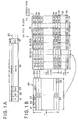
- one data sector 20 is firstly divided into a plurality of blocks, each of which is 172 bytes data, and each divided data (hereinafter, it is referred to as a "data block 33") is arranged in a vertical direction (refer to the left side of FIG. 1B). At this time, the data blocks 33 are arranged in 12 lines in the vertical direction.
- an ECC internal code (PI (Parity In) sign) 31 having 10 bytes data is affixed to the end of the data block 33 to constitute one correction block 34 (refer to right side of FIG.1B).
- the correction blocks 34 of 192 lines are divided for each one byte in the vertical direction from the beginning thereof, in the state that the 192 lines of the correction blocks 34 are arranged in the vertical direction.
- 16 ECC external codes (P0 (Parity Out) signs) 32 are affixed to each of the vertically divided data blocks. It is noted that the ECC external code 32 is also affixed to a portion of the ECC internal code 31 within the correction block 34.
- [D#. *] data of one byte is indicated by [D#. *].
- [D1. 0] indicates the data of one byte positioned at a first line and a zeroth column
- [D190. 170] indicates the data of one byte positioned at a 190th line and a 170th column.
- the ECC internal codes 31 are positioned at 172nd to 181st columns respectively
- the ECC external codes 32 are positioned at 192nd to 207th lines respectively.
- the correction blocks 34 are consecutively recorded on the DVD-R.
- the reason why the ECC block 30 is constituted so as to include both of the ECC internal code 31 and the ECC external code 32, as shown in the right side of FIG. 1B, is that the data arranged in the horizontal direction in FIG. 1B is corrected by the ECC internal code 31 and the data arranged in the vertical direction is corrected by the ECC external code 32. That is, it is possible to perform the error correction in both of the horizontal and vertical directions within the ECC block 30 shown in FIG. 1B.
- the ECC blocks 30 are firstly aligned along one line in a horizontal direction for each correction block 34, as shown in a top stage of FIG. 2, and then are interleaved to be divided into 16 recording sectors 40 (as shown in a second top stage of FIG. 2).
- the ID information 21 (refer to FIG. 1A) in the data sector 20 is positioned at a head portion of each recording sector 40.
- the recording sector 40 is divided into a plurality of data 41 each having 91 bytes, and a header H is appended to each data 41 (as shown in a third top stage of FIG. 2).
- one sync frame 42 is produced from one data 41 by 8-16-modulating the recording sector 40 including the pairs of the header H and the data 41.
- one recording sector 40 includes 26 sync frames 42.
- the 8-16-demodulation and de-interleave are performed at the time of reproducing the recorded information to thereby reproduce the original ECC block 30 while performing the effective error correction to accurately reproduce the record information.
- an information recording apparatus as an embodiment of the present invention for recording the record information onto the DVD-R 1 according to the physical format explained with reference to FIGS. 1A to 2 is explained with reference to FIGS. 3 to 5B.
- pre-pits or the like carrying address information on the DVD-R 1 are formed in advance on the information tracks, on which the record information is to be recorded, of the DVD-R 1.
- the address information on the DVD-R 1 is obtained by detecting the pre-pits.
- a record position on the DVD-R 1 where the record information is to be recorded is detected, so that the record information is recorded thereto.
- a configuration of the information recording apparatus of the embodiment is firstly explained with reference to FIG.3.
- an information recording apparatus S of the embodiment is provided with: a pick-up 2; a reproduction amplifier (AMP) 3; a decoder 4; a pre-pit signal decoder 5; a spindle motor 6; a servo circuit 7; a processor (CPU) 8; an encoder 9; a power control circuit 11; a laser drive circuit 12; and an interface 13.
- a record information signal S R indicating record information to be recorded is inputted through the interface 13 from an external host computer 14.
- the encoder 9 is-provided with a buffer memory 10.
- the pick-up 2 includes a laser diode, a deflection beam splitter, an objective lens, light detectors and the like (not shown), and irradiates a light beam B onto the information record surface of the DVD-R 1 on the basis of a laser drive signal S DL , and detects the pre-pits on the basis of a reflected light thereof to thereby record an encode signal S RE described later. Moreover, in a case of the existence of old record information which has been already recorded, the pick-up 2 detects this old record information on the basis of the reflected light of the light beam B.
- the reproduction amplifier 3 amplifies a detection signal S DT including the information corresponding to the pre-pits (and the information corresponding to the old record information which has already been recorded, if it exists) outputted by the pick-up 2, and outputs a pre-pit signal S PP corresponding to the pre-pits (and an amplified signal S P corresponding to the old record information, if it exists).
- the decoder 4 applies the 8-16-demodulation and the de-interleave to the amplified signal S P to thereby decode the amplified signal S P and then outputs a demodulated signal S DM , and a servo demodulated signal S SD .
- the pre-pit signal decoder 5 decodes the pre-pit signal S PP to thereby output a demodulated pre-pit signal S PD .
- the servo circuit 7 outputs to the pick-up 2 a pick-up servo control signal S SP for focus servo control and tracking servo control in the pick-up 2, on the basis of the demodulated pre-pit signal S PD and the servo demodulated signal S SD , and also outputs to the spindle motor 6 a spindle servo signal S SS for servo-controlling the rotation of the spindle motor 6 to rotate the DVD-R 1.
- the processor 8 outputs to the external a reproduction signal S OT corresponding to the old record information, which has been already recorded, on the basis of the demodulated signal S DM , and further outputs a buffer control signal S C so as to control the recording operation described later.
- the interface 13 performs an interface operation with respect to the record information signal S R transmitted from the host computer 14 so as to read it into the information recording apparatus S under the control of the processor 8, and outputs the record information signal S R to the encoder 9.
- the encoder 9 which includes an ECC generator, an 8-16 modulator, a scrambler and the like (not shown in the figure) as well as the buffer memory 10, affixes the ECC internal code 31 and the ECC external code 32 to the record information signal S R to thereby constitute the ECC block 30, and applies the interleave process, the 8-16 modulation process and the scramble process to the ECC block 30 to thereby output the encode signal S RE .
- the buffer memory 10 included in the encoder 9 temporarily stores the record information signal S R from the host computer 14 on the basis of the buffer control signal S C from the processor 8, and outputs the record information signal S R at a reading out rate corresponding to a recording rate for the encode signal S RE of the pick-up 2 with respect to the DVD-R 1.
- the record information signal S R is read out from the buffer memory 10 under the control of the buffer control signal S C , so that the generation process of the ECC block 30, the interleave process and so on are applied to this read out record information signal S R in the encoder 9 in the present embodiment.
- the power control circuit 11 outputs to the laser drive circuit 12 a drive signal S D to control an output of the laser diode (not shown) within the pick-up 2 on the basis of the encode signal S RE .
- the laser drive circuit 12 outputs to the laser diode the laser drive signal S DL for actually driving the laser diode to emit the light beam B on the basis of the drive signal S D .
- the information recording apparatus S may reproduce the information recorded on the DVD-R 1.
- the reproduction signal S OT is outputted to the external through the processor 8 on the basis of the demodulated signal S DM .
- FIG. 4 is a flow chart showing the recording operation for the record information in the embodiment, which is performed mainly by the processor 8.
- FIG. 5A shows a transition of the data amount of the record information corresponding to the record information signal S R in the buffer memory 10 during the recording operation shown in FIG. 4.
- FIG. 5B shows a change in the state of the data during the recording operation shown in FIG. 4.
- the record information signal S R is received from the host computer 14 through the interface 13, and is temporarily stored into the buffer memory 10 in the encoder 9 (step S1, as indicated by a portion P1 of the graph in FIG. 5A). Then, when the buffer memory 10 is filled with the record information signal S R , the processor 8 transmits a data transfer stopping command signal S S (which indicates the aforementioned data transfer stopping command to request for temporarily stopping the data transfer) to the host computer 14, and the processor 8 also transmits the buffer control signal S C to the buffer memory 10 so that the encoder 9 generates the encode signal S RE on the basis of the record information signal S R stored in the buffer memory 10.
- a data transfer stopping command signal S S S which indicates the aforementioned data transfer stopping command to request for temporarily stopping the data transfer
- step S2 it is started to record the encode signal S RE onto the DVD-R 1 by the power control circuit 11, the laser drive circuit 12, the pick-up 2 and so on (step S2).
- a UR flag in the processor 8 which indicates that the condition of the buffer memory 10 becomes the under run condition, is initialized i.e., reset to "0" (step S3).
- the data amount in the buffer memory 10 gradually decreases (as indicated by a portion P2 of the graph in FIG. 5A).
- step S4 the data amount in the buffer memory 10 is checked by the processor 8 while the output of the record information signal S R from the buffer memory 10 is continued. After that, it is judged by the processor 8 whether the UR flag is "1" (i.e., the buffer memory 10 is in the under run condition) and the data amount in the buffer memory 10 is not at the full level (i.e., the buffer memory 10 is not filled with the record information signal S R ) (step S5).
- step S6 since the UR flag is not "1" in the present occasion (step S5: NO), it is nextly judged whether or not the data amount in the buffer memory 10 is more than a level A set in advance (step S6).
- This level A corresponds to the data amount of the buffer memory 10, at which a data transfer request command signal S Q indicating the aforementioned data transfer request command to request for transferring the data in the next segment from the host computer 14 is to be outputted from the processor 8 to the host computer 14 (as indicated by the level A in FIG. 5A).
- step S6 NO, as indicated by a portion P3 of the graph in FIG.
- the data transfer request command signal S Q is transmitted from the processor 8 to the host computer 14 (step S7).
- the record information signal S R is transmitted from the host computer 14, the data amount in the buffer memory 10 gradually increases (as indicated by a portion P4 of the graph in FIG. 5A).
- the data amount in the buffer memory 10 gradually decreases (as indicated by a portion P5 of the graph in FIG. 5A). Then, it is judged by the processor 8 whether or not the data amount in the buffer memory 10 is more than a level B set in advance, which corresponds to a standard data amount at which the buffer memory 10 is judged as the under run condition (as indicated by the level B in FIG. 5A) (step S8).
- the level B is set to 48 Kbytes, for example.
- step S8 if it is judged that, since the record information signal S R is not still transmitted from the host computer 14, the data amount in the buffer memory 10 is not more than the level B (step S8: NO), it is concluded that the buffer memory 10 is in the under run condition (as indicated by a range of "under run” in FIG. 5A). Then, it is checked where a record position, at which the pick-up 2 is presently recording on the DVD-R 1, is positioned (step S9). Then, it is judged whether or not the record position is at a predetermined position at which recording onto the DVD-R 1 is to be temporarily stopped (step S10).
- this predetermined position at which recording is to be temporarily stopped in case of the under run condition, is set in a latter half portion of the 2nd sync frame 42 from the head of the ECC block 30.
- the record position is at this predetermined position (step S10: YES)
- recording is temporarily stopped at the latter half portion of the 2nd sync frame 42 from the head of the ECC block 30, and that the header H' indicating this 2nd sync frame 42 is stored into a RAM (Random Access Memory) in the processor 8.
- a timer in the processor 8 not illustrated is started, and the UR flag is set to "1" (step S11).
- step S11 the condition of the buffer memory 10 while the process at the step S11 is executed is explained with reference to FIG. 5B.
- step S8: NO the processor 8 controls the pick-up 2 etc., to temporality stop the recording operation in such a state that the encode signal S RE until a point (B) in the second top stage of FIG. 5B has been recorded (i.e., until the latter half portion of the 2nd sync frame 42 from the head of the ECC block 30) (step S11).
- the record information signal S R which corresponds to a range from a front half position of the 2nd sync frame 42 from the head of the ECC block 30 (e.g., the point (A) in the second top stage of FIG. 5B) to a point (C) in the second top stage of FIG. 5B, has been stored in the buffer memory 10.
- step S11 when recording is temporarily stopped (step S11), it is judged whether or not the timer of the processor 8, which has been started at the step S11, indicates a standard time C to judge a hung up condition of the host computer 14 (i. e. a trouble condition in which the host computer 14 cannot transmit the record information signal S R due to a failure of the CPU etc. thereof) (step S12). If the timer does not indicates the standard time C yet (step S12: NO), the operation flow returns to the step S4, since there is such a possibility that transferring the record information signal S R is re-started from the host computer 14, so as to check the data amount in the buffer memory 10.
- step S12 if transferring the record information signal S R is not re-started from the host computer 14 yet, since the judgment result at the step S5 becomes "YES”, the operation flow branches to the step S12, so as to check the value of the timer again. Then, if transferring the record information signal S R from the host computer 14 is not re-started until the value of the timer reaches the value C (step S12: YES), since the possibility that the host computer 14 is in the hung up condition is high, an error signal S E , which indicates that the possibility of the hung up condition is high, is transmitted to the host computer 14 (step S13), and the processes are finished.
- step S6 since the buffer memory 10 is filled (step S6: YES), it is judged whether or not the UR flag is set to "1" at the step S14.
- step S14 since the UR flag is set to "1" (step S14: YES), the UR flag is initialized i. e. set to "0" (step S17). Then, when recording is re-started, the header H' of the sync frame 42 where recording has been stopped, which is stored in the RAM of the processor 8 (i.e., the header H' of the 2nd sync frame 42 from the head of the ECC block 30) is read out from the RAM.
- step S18 it is judged whether or not the record position of the pick-up 2 is at a connect position, which is the head position of the 2nd sync frame 42 from the head of the ECC block 30, so as to re-start recording from the head of the sync frame 42, which is read out from the RAM including a stopped position where recording has been temporarily stopped, in correspondence with the stopped position (as indicated by the point (B) in FIG. 5B) (step S18). If the record position is at the connect position (step S18: YES), recording is re-started as it is (step S20). If the record position is not at the connect position (step S18: NO), the pick-up 2 is moved to the head position (i.e. the connect position) of the sync frame 42 (step S19), and recording is re-started (step S20, as indicated by a portion P7 of the graph in FIG. 5A).
- one series of the record information signal S R is constructed by adding the latter half portion of the record information signal S R after re-starting the transmission from the host computer 14, with respect to the portion of the record information signal S R , which remains in the buffer memory 10 at the time of temporarily stopping recording (i.e. the portion of the record information signal S R corresponding to the area from the point (A) to the point (C) in the second top stage of FIG. 5B, which is stored in the buffer memory 10).
- the encode signal S RE corresponding to this one series of the record information signal S R is re-recorded from the head of the 2nd sync frame 42 from the head of the ECC block 30 (as indicated by the third top stage of FIG. 5B).
- the encode signal S RE is overwritten from the head of the 2nd sync frame 42 (from the head of the ECC block 30) to the position corresponding to the point (B) as shown in the bottom stage of FIG. 5B.
- the data in this overwritten portion i.e. a data destroyed area D in the bottom stage of FIG. 5B
- the data destroyed area D is within one sync frame 42, it is within an error correctable area for the error correction at the time of reproducing the record information, so that the erroneous reproduction is not caused at the time of reproduction.
- step S20 when recording is re-started, the operation flow returns to the step S4, so as to check the data amount in the buffer memory 10 and prepare for the next under run condition, again.
- step S6 even if the data amount in the buffer memory 10 is less than the level A (step S6: NO), by the transmission of the record information signal S R from the host computer 14 in response to the data transfer requesting command signal S Q (step S7), if the data amount in the buffer memory 10 becomes more than the level B (step S8: YES), the operation flow branches to the step S14, so as to perform recording again.
- step S10 if the record position of the pick-up 2 is not at the predetermined position (i.e., not in the latter half portion of the 2nd sync frame 42 from the head of the ECC block 30) although the buffer memory 10 is in the under run condition (step S10: NO), the operation flow branches to the step S14 so as to continue recording until the record position reaches this predetermined position.
- step S14 if the under run condition is not generated or is dissolved after it is once generated, since the UR flag is not set to "1" (step S14: NO), recording the encode signal S RE is continued (step S15). Then, it is judged whether or not the transfer of the record information signal S R is all ended in accordance with an end command etc. for the record information signal S R from the host computer 14 (step S16). If it is all ended (step S16: YES), the recording operation is ended. If the transfer of the record information signal S R is not all ended (step S16: NO), the operation flow returns to the step S4 so as to continue the recording operation, check the data amount in the buffer memory 10 and prepare for the next under run condition.
- the recording operation in the embodiment in case that the data amount in the buffer memory 10 becomes less than the predetermined level B, recording is temporarily stopped in the latter half portion of the 2nd sync frame 42 from the head of the ECC block 30, and recording is re-started from the head of the 2nd sync frame 42 from the head of the ECC block 30 when the data amount recovers to be more than the predetermined level B (or the level A). Accordingly, even if the data amount in the buffer memory 10 decreases by the generation of the under run condition in the record information signal S R , it is possible to maintain the continuity of the data at the time of reproducing the encode signal S RE after recording the DVD-R 1, so that a precise reproduction can be performed.
- the record information signal S R is outputted from the host computer 14, even if the record information signal S R is ceased due to the failure of the host computer 14 etc. and the generation of the encode signal S RE is ceased in due course, the encode signal S RE can be continuously recorded on the DVD-R 1.
- the processor 8 transmits the error signal S E to the host computer 14 when the data amount in the buffer memory 10 remains less than the level B after recording the encode signal S RE is stopped, it is possible for the host computer 14 to recognize that it is in the error condition.
- recording is temporarily stopped within the 2nd sync frame 42 from the head of the ECC block 30, and recording is re-started from the head of this sync frame 42.
- the present invention is not limited to this.
- recording may be re-started while overwriting from another sync frame 42 which is prior in time sequence, by a data amount corresponding to a plurality of sync frames, to one sync frame 42 at which recording has been stopped, as long as it is within the area correctable by the error correction capability at the time of reproducing the ECC block 30.
- the recording operation can be temporarily stopped at any sync frame 42 within the area correctable by the error correction capability at the time of reproducing the ECC block 30.
- the record information signal S R is temporarily stored in the buffer memory 10
- the record information signal S R is read out so that the generation process of the ECC block 30, the interleave process and so on are applied to this read out record information signal S R .
- the present invention is not limited to this.
- the processed data i.e., the encode signal S RE may be temporarily stored in the buffer memory 10, and then, the stored data may be recorded onto the DVD-R 1.
- the present invention is not limited to this.
- the present invention can be applied to a hard disc apparatus, a flexible disc apparatus and so on.
Abstract
Description
- The present invention is related with an information recording method and apparatus for recording record information onto an information record medium of write-once-read-many type, such as a high-density optical disc and the like, which is used as an external storage device for a host computer and is represented by a DVD-R (DVD-Recordable) on which the information can be recorded only once.
- This type of information recording apparatus performs an operation of recording various data inputted from a host computer onto an information record medium of write-once-read-many type (hereinbelow, it is referred to as a "DVD-R etc."), which is recordable only once, under the control of the host computer. At the time of this recording operation, the transfer rate, at which the data is transferred from the host computer to the information recording apparatus, and the record rate, at which the transferred data is recorded by the information recording apparatus onto the DVD-R etc., are hardly coincident with each other. The transfer rate from the host computer is often set to be higher than the record rate.
- Therefore, as a method of canceling or compensating the difference between the transfer rate and the record rate, there is a method of canceling or compensating this rate difference, by equipping a buffer memory to the information recording apparatus, storing the transferred data at the transfer rate temporarily in the buffer memory, and reading the stored data at the rate corresponding to the record rate.
- By the way, in the information recording apparatus equipped with this buffer memory, the balance between the data amount read from the buffer memory and the data amount written into the buffer memory may be destroyed due to the difference between the transfer rate and the record rate. Namely, the data amount written into the buffer memory may become larger than the data amount read from the buffer memory, so that a condition may happen in which the storage amount of the data in the buffer memory is continuously increased. Thus, when the storage of the data in one segment which has been transferred is completed or finished, the processor for controlling the information recording apparatus transmits to the host computer a command to request for temporarily stopping the data transfer (hereinbelow, it is referred to as a "data transfer stopping command"), keeps to monitor the empty capacity of the recordable area in the buffer memory which increases while recording the data onto the DVD-R etc., and transmits to the host computer a command to request for transferring the data in the next segment from the host computer (hereinbelow, it is referred to as a "data transfer requesting command") when the monitored empty capacity becomes higher than a predetermined level. Then, when the new data is transferred and is accumulated in the buffer memory and the empty capacity in the buffer memory becomes "0" or less than a predetermined level, the data transfer stopping command is transmitted again to the host computer. Then, the host computer performs the data transfer control on the basis of the above described data transfer stopping command and the data transfer requesting command.
- By the way, various peripheral apparatuses other than the information recording apparatus, such as a hard disc drive etc., may be connected to the host computer. Each of the operation speeds of these peripheral apparatuses are often lower than the operating speed of the host computer. Thus, in a so-called batch process in which the host computer performs one process for one peripheral apparatus and changes over to another process after the one process is completed or finished, a priority order may be set by the host computer with respect to each of the processes for the peripheral apparatuses, and each of the processes for the peripheral apparatuses may be performed in a time divisional manner on the basis of the priority orders, in order to improve the utilization efficiency of the host computer.
- At this time, it is normal that, as the process is more closely related with a so-called "man-machine-interface" which is directly related to the user of the host computer, the priority order thereof is set higher. Thus, even if the data transfer requesting command from the information recording apparatus is received by the host computer, the host computer may not immediately respond to this data transfer requesting command during the prosecution of the process for another peripheral apparatus, which has the higher priority order than the information recording apparatus. Namely, although the information recording apparatus performs recording the data onto the DVD-R etc., a condition may happen in which the data to be recorded is not stored or accumulated in the buffer memory of the information recording apparatus i.e., a so-called "under run" condition may happen in the information recording apparatus.
- If this under run condition happens, the continuity of the data in the data reading operation from the buffer memory cannot be maintained. In this case, according to the conventional information recording apparatus for the DVD-R etc., the recording operation is temporarily stopped, and, after the under run condition is dissolved, new data in each predetermined segment is recorded again, which includes the data which has been already recorded, onto the DVD-R etc. at a new recordable area thereof.
- However, in the information recording apparatus for the DVD-R etc., since the data which has been once recorded cannot be erased anymore, the recordable area on the DVD-R etc., where the data has been once recorded when the under run condition happens, becomes an unavailable area at which the data is not continuous and which will be jumped when the DVD-R etc. is reproduced later. Therefore, this unavailable area is really inefficient in the DVD-R etc. on which the data in large amount is to be recorded, and the recordable area of the DVD-R etc. cannot be utilized efficiently, which is a problem.
- Further, in case that the data which continuity is not maintained exists as it is on the DVD-R etc., an error operation may be caused at the time of reproduction, which is another problem.
- The present invention is proposed from the viewpoint of the above mentioned problems. It is therefore an object of the present invention to provide an information recording method and apparatus, which can record the data such that, even in case that the under run condition happens, the recordable area of the DVD-R etc. is not wasted, and the data can be precisely reproduced at the time of reproduction.
- The above object of the present invention can be achieved by an information recording method provided with: a buffering process for temporarily storing information, which is inputted from the external and is to be recorded, in a buffer memory; a generating process for reading out the temporarily stored information from the buffer memory, and applying a predetermined signal process, such as an interleave process, an 8-16 modulation process or the like, onto the read out information to generate processed information comprising a plurality of record units, such as a sync frame or the like; a recording process of recording the processed information onto an information record medium, such as a DVD-R or the like; a detecting process of detecting a storage amount of the temporarily stored information in the buffer memory; a stop controlling process of controlling the recording process to stop recording the processed information within a presently-recorded record unit among the record units, which includes the processed information which is being recorded by the recording process, when the detected storage amount becomes less than a predetermined value; and a re-start controlling process of controlling the recording process to re-start recording the processed information onto the information record medium from one of the record units, which includes the processed information to be recorded prior in time sequence to the presently-recorded record unit, or which is identical with the presently-recorded record unit, when the detected storage amount becomes more than the predetermined value.
- According to the information recording method of the present invention, the storage amount of the temporarily stored information in the buffer memory is detected by the detecting process. When the detected storage amount becomes less than the predetermined value, the recording process stops recording the processed information within the presently-recorded record unit, which includes the processed information which is being recorded by the recording process, under the control of the stop controlling process. After that, when the detected storage amount becomes more than the predetermined value, the recording process re-starts recording the processed information onto the information record medium from one of the record units, which includes the processed information to be recorded prior in time sequence to the presently-recorded record unit, or which is identical with the presently-recorded record unit, under the control of the re-start controlling process.
- Therefore, even if the storage amount in the buffer memory certainly decreases due to a generation of a discontinuity in the information before recording, the continuity of the processed information can be secured at the time of reproducing the processed information, which has been recorded on the information record medium, so that a precise reproduction is enabled.
- Further, since the processed information can be recorded continuously on the information record medium, the recordable area on the information record medium is not wasted.
- Consequently, the recording and reproducing operations can be precisely and certainly performed while efficiently utilizing the recordable area of the information record medium, such as a DVD-R or the like, according to the present invention.
- In one aspect of the information recording method of the present invention, the stop controlling process includes a record unit-storing process of storing the presently-recorded record unit, and the re-start controlling process controls the recording process to re-start recording the processed information from one of the record units, which includes the processed information to be recorded prior in time sequence to the presently-recorded record unit stored by the record unit storing process, or which is identical with the presently-recorded record unit stored by the record unit storing process.
- According to this aspect, the presently-recorded record unit is stored by the record unit storing process. Then, the recording process re-starts recording the processed information from one of the record units, which includes the processed information to be recorded prior in time sequence to the presently-recorded record unit stored by the record unit storing process, or which is identical with the presently-recorded record unit stored by the record unit storing process, under the control of the re-start controlling process.
- Therefore, the continuity of the processed information can be surely secured at the time of reproducing the processed information, which has been recorded on the information record medium, so that a precise reproduction is enabled.
- In another aspect of the information recording method of the present invention, the processed information is divided into a plurality of error correction units, such as ECC blocks or the like, which are set in advance, the stop controlling process controls the recording process to stop recording the processed information within a second record unit from a head of each of the error correction units among the record units included in each of the error correction units, as the presently-recorded record unit, and the re-start controlling process controls the recording process to re-start recording the processed information onto the information record medium from a head of the presently-recorded record unit.
- According to this aspect, the recording process stops recording the processed information within the second record unit from the head of each of the error correction units among the record units included in each of the error correction units, as the presently-recorded record unit, under the control of the stop controlling process. Then, the recording process re-starts recording the processed information onto the information record medium from the head of the presently-recorded record unit, under the control of the re-start controlling process.
- Therefore, the recording operation can be re-started within one record unit, so that the recordable area on the information record medium can be even more efficiently utilized.
- Further, since the area where the processed information is overwritten is only within the presently-recorded record unit, it is easy to perform an error correction process at the time of reproducing the processed information.
- In another aspect of the information recording method of the present invention, the information is inputted into the buffer memory from an external computer apparatus, such as a host computer or the like.
- According to this aspect, since the information is inputted from the external computer apparatus, in case that the input of the information is ceased due to a failure etc. of the external computer apparatus and that the generation of the processed information is ceased in due course, the processed information can be still recorded continuously on the information record medium.
- In this aspect, the stop controlling process may include an error signal transmitting process of transmitting an error signal, which indicates an error condition in the external computer apparatus, to the external computer apparatus when the detected storage amount remains less than the predetermined value after the recording process stops recording the processed information.
- According to this case, after the recording process stops recording the processed information, when the detected storage amount remains less than the predetermined value, the error signal is transmitted to the external computer apparatus by the error signal transmitting process. Thus, it is possible to inform the external computer apparatus that it is in the error condition.
- In this aspect also, the information recording method may be further provided with a stop command outputting process of outputting to the external computer apparatus a data transfer stop command to stop a transmission of the information to the buffer memory, when the detected storage amount becomes a predetermined full level of the buffer memory.
- According to this case, when the detected storage amount becomes the predetermined full level of the buffer memory, the data transfer stop command to stop the transmission of the information to the buffer memory is outputted to the external computer apparatus, by the stop command outputting process. Thus, it is possible to prevent the buffer memory from becoming in the memory full condition.
- In this aspect also, the information recording method may be further provided with a request command outputting process of outputting to the external computer apparatus a data transfer request command to request a transmission of the information to the buffer memory, when the detected storage amount becomes a predetermined storable level of the buffer memory.
- According to this case, when the detected storage amount becomes the predetermined storable level of the buffer memory, the data transfer request command to request the transmission of the information to the buffer memory is outputted to the external computer apparatus, by the request command outputting process. Thus, it is possible to efficiently utilize the buffer memory during the recording operation.
- The above object of the present invention can be also achieved by an information recording apparatus provided with: a buffer memory for temporarily storing information, which is inputted from the external and is to be recorded; a generating device for reading out the temporarily stored information from the buffer memory, and applying a predetermined signal process onto the read out information to generate processed information comprising a plurality of record units; a recording device for recording the processed information onto an information record medium; a detecting device for detecting a storage amount of the temporarily stored information in the buffer memory; a stop controlling device for controlling the recording device to stop recording the processed information within a presently-recorded record unit among the record units, which includes the processed information which is being recorded by the recording device, when the detected storage amount becomes less than a predetermined value; and a re-start controlling device for controlling the recording device to re-start recording the processed information onto the information record medium from one of the record units, which includes the processed information to be recorded prior in time sequence to the presently-recorded record unit, or which is identical with the presently-recorded record unit, when the detected storage amount becomes more than the predetermined value.
- According to the information recording apparatus of the present invention, the storage amount of the temporarily stored information in the buffer memory is detected by the detecting device. When the detected storage amount becomes less than the predetermined value, the recording device stops recording the processed information within the presently-recorded record unit, which includes the processed information which is being recorded by the recording device, under the control of the stop controlling device. After that, when the detected storage amount becomes more than the predetermined value, the recording device re-starts recording the processed information onto the information record medium from one of the record units, which includes the processed information to be recorded prior in time sequence to the presently-recorded record unit, or which is identical with the presently-recorded record unit, under the control of the re-start controlling device.
- Therefore, even if the storage amount in the buffer memory certainly decreases due to a generation of a discontinuity in the information before recording, the continuity of the processed information can be secured at the time of reproducing the processed information, which has been recorded on the information record medium, so that a precise reproduction is enabled.
- Further, since the processed information can be recorded continuously on the information record medium, the recordable area on the information record medium is not wasted.
- Consequently, the recording and reproducing operations can be precisely and certainly performed while efficiently utilizing the recordable area of the information record medium, such as a DVD-R or the like, according to the present invention.
- In one aspect of the information recording apparatus of the present invention, the stop controlling device includes a record unit storing device for storing the presently-recorded record unit, and the re-start controlling device controls the recording device to re-start recording the processed information from one of the record units, which includes the processed information to be recorded prior in time sequence to the presently-recorded record unit stored by the record unit storing device, or which is identical with the presently-recorded record unit stored by the record unit storing device.
- According to this aspect, the presently-recorded record unit is stored by the record unit storing device. Then, the recording device re-starts recording the processed information from one of the record units, which includes the processed information to be recorded prior in time sequence to the presently-recorded record unit stored by the record unit storing device, or which is identical with the presently-recorded record unit stored by the record unit storing device, under the control of the re-start controlling device.
- Therefore, the continuity of the processed information can be surely secured at the time of reproducing the processed information, which has been recorded on the information record medium, so that a precise reproduction is enabled.
- In another aspect of the information recording apparatus of the present invention, the processed information is divided into a plurality of error correction units which are set in advance, the stop controlling device controls the recording device to stop recording the processed information within a second record unit from a head of each of the error correction units among the record units included in each of the error correction units, as the presently-recorded record unit, and the re-start controlling device controls the recording device to re-start recording the processed information onto the information record medium from a head of the presently-recorded record unit.
- According to this aspect, the recording device stops recording the processed information within the second record unit from the head of each of the error correction units among the record units included in each of the error correction units, as the presently-recorded record unit, under the control of the stop controlling device. Then, the recording device re-starts recording the processed information onto the information record medium from the head of the presently-recorded record unit, under the control of the re-start controlling device.
- Therefore, the recording operation can be re-started within one record unit, so that the recordable area on the information record medium can be even more efficiently utilized.
- Further, since the area where the processed information is overwritten is only within the presently-recorded record unit, it is easy to perform an error correction process at the time of reproducing the processed information.
- In another aspect of the information recording apparatus of the present invention, the information is inputted into the buffer memory from an external computer apparatus.
- According to this aspect, since the information is inputted from the external computer apparatus, in case that the input of the information is ceased due to a failure etc. of the external computer apparatus and that the generation of the processed information is ceased in due course, the processed information can be still recorded continuously on the information record medium.
- In this aspect, the stop controlling device may include an error signal transmitting device for transmitting an error signal, which indicates an error condition in the external computer apparatus, to the external computer apparatus when the detected storage amount remains less than the predetermined value after the recording device stops recording the processed information.
- According to this case, after the recording device stops recording the processed information, when the detected storage amount remains less than the predetermined value, the error signal is transmitted to the external computer apparatus by the error signal transmitting device. Thus, it is possible to inform the external computer apparatus that it is in the error condition.
- In this aspect also, the information recording apparatus may be further provided with a stop command outputting device for outputting to the external computer apparatus a data transfer stop command to stop a transmission of the information to the buffer memory, when the detected storage amount becomes a predetermined full level of the buffer memory.
- According to this case, when the detected storage amount becomes the predetermined full level of the buffer memory, the data transfer stop command to stop the transmission of the information to the buffer memory is outputted to the external computer apparatus, by the stop command outputting device. Thus, it is possible to prevent the buffer memory from becoming in the memory full condition.
- In this aspect also, the information recording apparatus may be further provided with a request command outputting device for outputting to the external computer apparatus a data transfer request command to request a transmission of the information to the buffer memory, when the detected storage amount becomes a predetermined storable level of the buffer memory.
- According to this case, when the detected storage amount becomes the predetermined storable level of the buffer memory, the data transfer request command to request the transmission of the information to the buffer memory is outputted to the external computer apparatus, by the request command outputting device. Thus, it is possible to efficiently utilize the buffer memory during the recording operation.
- The nature, utility, and further features of this invention will be more clearly apparent from the following detailed description with respect to preferred embodiments of the invention when read in conjunction with the accompanying drawings briefly described below.
- FIG.1A is a diagram showing a data structure of record information in an embodiment;
- FIG. 1B is a diagram showing a configuration of an ECC block in the record information in the embodiment;
- FIG. 2 is a diagram showing a physical format of the record information in the embodiment;
- FIG. 3 is a block diagram showing a schematic configuration of an information recording apparatus according to the present invention;
- FIG.4 is a flow chart showing an information recording operation of the embodiment;
- FIG. 5A is a diagram showing a transition of the data amount in a buffer memory during the information recording operation in the embodiment; and
- FIG. 5B is a diagram showing a change in the state of the data during the information recording operation in the embodiment.
-
- Next, a preferred embodiment of the present invention will be explained with reference to the accompanied drawings. In the following explanations, the present invention is applied to an information recording apparatus for recording record information onto a DVD-R as an embodiment of the present invention.
- At first, a physical format of the record information on the DVD-R and an error correcting process for the record information are explained with reference to FIGS. 1 and 2.
- The error correcting process for the DVD-R and an ECC block, which serves as an error correction unit in the error correcting process in the embodiment, are firstly explained with reference to FIGS.1A and 1B.
- As shown in FIG. 1A, the record information recorded on the DVD-R has a physical structure including a plurality of
data sectors 20. Onedata sector 20 is composed, in an order from a head portion thereof, of: an ID information (ID) 21 indicative of a start position of thedata sector 20; an ID information error correction code (IEC) 22 for correcting errors in theID information 21; reserve data (RSV) 23;data 24 which is the main data to be recorded; and an error detection code (EDC) 25 for detecting errors in thedata 24. The record information to be recorded is constituted by a plurality of thedata sectors 20 arranged in sequence. - Next, a process in an encoder described later for constituting the ECC block by the
data sectors 20 is explained with reference to FIG. 1B. - As shown in FIG. 1B, when constituting an
ECC block 30 by thedata sectors 20, onedata sector 20 is firstly divided into a plurality of blocks, each of which is 172 bytes data, and each divided data (hereinafter, it is referred to as a "data block 33") is arranged in a vertical direction (refer to the left side of FIG. 1B). At this time, the data blocks 33 are arranged in 12 lines in the vertical direction. - For each data block 33 arranged in the vertical direction, an ECC internal code (PI (Parity In) sign) 31 having 10 bytes data is affixed to the end of the data block 33 to constitute one correction block 34 (refer to right side of FIG.1B). At this stage, the correction blocks 34 to which the ECC
internal codes 31 are affixed are arranged in 12 lines in the vertical direction. After that, this process is repeated with respect to 16data sectors 20. Accordingly, the correction blocks 34 of 192 (=12×16) lines are obtained. - Next, the correction blocks 34 of 192 lines are divided for each one byte in the vertical direction from the beginning thereof, in the state that the 192 lines of the correction blocks 34 are arranged in the vertical direction. Then, 16 ECC external codes (P0 (Parity Out) signs) 32 are affixed to each of the vertically divided data blocks. It is noted that the ECC
external code 32 is also affixed to a portion of the ECCinternal code 31 within thecorrection block 34. - From the above mentioned process, one
ECC block 30 including 16data sectors 20 is produced as shown in FIG. 1B (the right side). At this time, a total amount of the information included within oneECC block 30 is expressed by an equation described below. - The actual data 24 (i.e., other than the ECC codes) in it is expressed by an equation described below.
- In the
ECC block 30 shown in FIG. 1B, data of one byte is indicated by [D#. *]. For example, [D1. 0] indicates the data of one byte positioned at a first line and a zeroth column, and [D190. 170] indicates the data of one byte positioned at a 190th line and a 170th column. Thus, the ECCinternal codes 31 are positioned at 172nd to 181st columns respectively, and the ECCexternal codes 32 are positioned at 192nd to 207th lines respectively. - The correction blocks 34 are consecutively recorded on the DVD-R.
- The reason why the
ECC block 30 is constituted so as to include both of the ECCinternal code 31 and the ECCexternal code 32, as shown in the right side of FIG. 1B, is that the data arranged in the horizontal direction in FIG. 1B is corrected by the ECCinternal code 31 and the data arranged in the vertical direction is corrected by the ECCexternal code 32. That is, it is possible to perform the error correction in both of the horizontal and vertical directions within theECC block 30 shown in FIG. 1B. - More concretely, for example, even if a certain one of the correction blocks 34 (which are, as mentioned above, consecutively recorded on the DVD-R and each of which has the data of 182 bytes in total including the ECC
internal codes 31 for one line) is entirely destroyed by a scratch or the like existing on the DVD-R, it is merely the one-byte data destruction with respect to the ECCexternal codes 32 at one column, as viewed in the vertical direction. Thus, by carrying out the error correction using the ECCexternal codes 32 at each column, it is possible to appropriately carry out the error correction to correctly reproduce the original information from the destroyed information, even though onecorrection block 34 is entirely destroyed. - The manner of actually recording onto the DVD-R the
data sectors 20 included in the ECC blocks 30 shown in FIG. 1B is explained with reference to FIG.2. In FIG.2, the data indicated in [D#. *] corresponds to the data described in the right side of FIG.1B. Incidentally, processes at the time of recording thedata sector 20 in FIG. 2 (i. e. an interleave process and an 8-16 modulation process) are processes performed by the encoder described later. - At the time of recording the ECC blocks 30 onto the DVD-R, the ECC blocks 30 are firstly aligned along one line in a horizontal direction for each
correction block 34, as shown in a top stage of FIG. 2, and then are interleaved to be divided into 16 recording sectors 40 (as shown in a second top stage of FIG. 2). At this time, onerecording sector 40 includes information of 2366 bytes (= 37856 bytes / 16), and that thedata sectors 20, the ECCinternal codes 31 and the ECCexternal codes 32 are intermingled and included in eachrecording sector 40. However, the ID information 21 (refer to FIG. 1A) in thedata sector 20 is positioned at a head portion of eachrecording sector 40. - The
recording sector 40 is divided into a plurality ofdata 41 each having 91 bytes, and a header H is appended to each data 41 (as shown in a third top stage of FIG. 2). After that, onesync frame 42 is produced from onedata 41 by 8-16-modulating therecording sector 40 including the pairs of the header H and thedata 41. At this time, onesync frame 42 is composed of a header H' and data 43 (as shown in a bottom stage of FIG. 2). Further, an information amount within onesync frame 42 is expressed by an equation described below. - Then, the information is written onto a DVD-
R 1 in a form of the continuous sync frames 42. At this time, onerecording sector 40 includes 26 sync frames 42. - By constituting the above explained physical format and recording the record information onto the DVD-R, the 8-16-demodulation and de-interleave (refer to FIG. 2) are performed at the time of reproducing the recorded information to thereby reproduce the
original ECC block 30 while performing the effective error correction to accurately reproduce the record information. - Next, an information recording apparatus as an embodiment of the present invention for recording the record information onto the DVD-
R 1 according to the physical format explained with reference to FIGS. 1A to 2 is explained with reference to FIGS. 3 to 5B. Here, the following assumptions are made in the embodiment described below. Namely, pre-pits or the like carrying address information on the DVD-R 1 are formed in advance on the information tracks, on which the record information is to be recorded, of the DVD-R 1. Then, at the time of recording the record information, the address information on the DVD-R 1 is obtained by detecting the pre-pits. By this, a record position on the DVD-R 1 where the record information is to be recorded is detected, so that the record information is recorded thereto. - A configuration of the information recording apparatus of the embodiment is firstly explained with reference to FIG.3.
- As shown in FIG. 3, an information recording apparatus S of the embodiment is provided with: a pick-
up 2; a reproduction amplifier (AMP) 3; adecoder 4; apre-pit signal decoder 5; aspindle motor 6; aservo circuit 7; a processor (CPU) 8; anencoder 9; apower control circuit 11; alaser drive circuit 12; and aninterface 13. To the information recording apparatus S, a record information signal SR indicating record information to be recorded is inputted through theinterface 13 from anexternal host computer 14. - The
encoder 9 is-provided with abuffer memory 10. - Next, a whole operation is explained.
- The pick-
up 2 includes a laser diode, a deflection beam splitter, an objective lens, light detectors and the like (not shown), and irradiates a light beam B onto the information record surface of the DVD-R 1 on the basis of a laser drive signal SDL, and detects the pre-pits on the basis of a reflected light thereof to thereby record an encode signal SRE described later. Moreover, in a case of the existence of old record information which has been already recorded, the pick-up 2 detects this old record information on the basis of the reflected light of the light beam B. - Then, the
reproduction amplifier 3 amplifies a detection signal SDT including the information corresponding to the pre-pits (and the information corresponding to the old record information which has already been recorded, if it exists) outputted by the pick-up 2, and outputs a pre-pit signal SPP corresponding to the pre-pits (and an amplified signal SP corresponding to the old record information, if it exists). - After that, the
decoder 4 applies the 8-16-demodulation and the de-interleave to the amplified signal SP to thereby decode the amplified signal SP and then outputs a demodulated signal SDM, and a servo demodulated signal SSD. - On the other hand, the
pre-pit signal decoder 5 decodes the pre-pit signal SPP to thereby output a demodulated pre-pit signal SPD. - Then, the
servo circuit 7 outputs to the pick-up 2 a pick-up servo control signal SSP for focus servo control and tracking servo control in the pick-up 2, on the basis of the demodulated pre-pit signal SPD and the servo demodulated signal SSD, and also outputs to the spindle motor 6 a spindle servo signal SSS for servo-controlling the rotation of thespindle motor 6 to rotate the DVD-R 1. - Along with this, the
processor 8 outputs to the external a reproduction signal SOT corresponding to the old record information, which has been already recorded, on the basis of the demodulated signal SDM, and further outputs a buffer control signal SC so as to control the recording operation described later. - On the other hand, the
interface 13 performs an interface operation with respect to the record information signal SR transmitted from thehost computer 14 so as to read it into the information recording apparatus S under the control of theprocessor 8, and outputs the record information signal SR to theencoder 9. - The
encoder 9, which includes an ECC generator, an 8-16 modulator, a scrambler and the like (not shown in the figure) as well as thebuffer memory 10, affixes the ECCinternal code 31 and the ECCexternal code 32 to the record information signal SR to thereby constitute theECC block 30, and applies the interleave process, the 8-16 modulation process and the scramble process to theECC block 30 to thereby output the encode signal SRE. At this time, thebuffer memory 10 included in theencoder 9 temporarily stores the record information signal SR from thehost computer 14 on the basis of the buffer control signal SC from theprocessor 8, and outputs the record information signal SR at a reading out rate corresponding to a recording rate for the encode signal SRE of the pick-up 2 with respect to the DVD-R 1. - More concretely, after the record information signal SR is temporarily stored in the
buffer memory 10, the record information signal SR is read out from thebuffer memory 10 under the control of the buffer control signal SC, so that the generation process of theECC block 30, the interleave process and so on are applied to this read out record information signal SR in theencoder 9 in the present embodiment. - Then, the
power control circuit 11 outputs to the laser drive circuit 12 a drive signal SD to control an output of the laser diode (not shown) within the pick-up 2 on the basis of the encode signal SRE. - After that, the
laser drive circuit 12 outputs to the laser diode the laser drive signal SDL for actually driving the laser diode to emit the light beam B on the basis of the drive signal SD. - Further, the information recording apparatus S may reproduce the information recorded on the DVD-
R 1. In that case, the reproduction signal SOT is outputted to the external through theprocessor 8 on the basis of the demodulated signal SDM. - A recording operation for the record information in the embodiment is explained with reference to FIGS.4 to 5B. FIG. 4 is a flow chart showing the recording operation for the record information in the embodiment, which is performed mainly by the
processor 8. FIG. 5A shows a transition of the data amount of the record information corresponding to the record information signal SR in thebuffer memory 10 during the recording operation shown in FIG. 4. FIG. 5B shows a change in the state of the data during the recording operation shown in FIG. 4. - In FIG. 4, at first, when the information recording apparatus S is started, the record information signal SR is received from the
host computer 14 through theinterface 13, and is temporarily stored into thebuffer memory 10 in the encoder 9 (step S1, as indicated by a portion P1 of the graph in FIG. 5A). Then, when thebuffer memory 10 is filled with the record information signal SR, theprocessor 8 transmits a data transfer stopping command signal SS (which indicates the aforementioned data transfer stopping command to request for temporarily stopping the data transfer) to thehost computer 14, and theprocessor 8 also transmits the buffer control signal SC to thebuffer memory 10 so that theencoder 9 generates the encode signal SRE on the basis of the record information signal SR stored in thebuffer memory 10. Then, it is started to record the encode signal SRE onto the DVD-R 1 by thepower control circuit 11, thelaser drive circuit 12, the pick-up 2 and so on (step S2). Next, a UR flag in theprocessor 8, which indicates that the condition of thebuffer memory 10 becomes the under run condition, is initialized i.e., reset to "0" (step S3). At this time, when recording is started at the step S2, the data amount in thebuffer memory 10 gradually decreases (as indicated by a portion P2 of the graph in FIG. 5A). - Next, the data amount in the
buffer memory 10 is checked by theprocessor 8 while the output of the record information signal SR from thebuffer memory 10 is continued (step S4). After that, it is judged by theprocessor 8 whether the UR flag is "1" (i.e., thebuffer memory 10 is in the under run condition) and the data amount in thebuffer memory 10 is not at the full level (i.e., thebuffer memory 10 is not filled with the record information signal SR) (step S5). - At the step S5, since the UR flag is not "1" in the present occasion (step S5: NO), it is nextly judged whether or not the data amount in the
buffer memory 10 is more than a level A set in advance (step S6). This level A corresponds to the data amount of thebuffer memory 10, at which a data transfer request command signal SQ indicating the aforementioned data transfer request command to request for transferring the data in the next segment from thehost computer 14 is to be outputted from theprocessor 8 to the host computer 14 (as indicated by the level A in FIG. 5A). Then, if the data amount is not more than the level A (step S6: NO, as indicated by a portion P3 of the graph in FIG. 5A), the data transfer request command signal SQ is transmitted from theprocessor 8 to the host computer 14 (step S7). In response to this, as the record information signal SR is transmitted from thehost computer 14, the data amount in thebuffer memory 10 gradually increases (as indicated by a portion P4 of the graph in FIG. 5A). - At this stage, when it is stopped to transfer the record information signal SR from the
host computer 14, since the recording operation onto the DVD-R 1 is still continued, the data amount in thebuffer memory 10 gradually decreases (as indicated by a portion P5 of the graph in FIG. 5A). Then, it is judged by theprocessor 8 whether or not the data amount in thebuffer memory 10 is more than a level B set in advance, which corresponds to a standard data amount at which thebuffer memory 10 is judged as the under run condition (as indicated by the level B in FIG. 5A) (step S8). Here, more concretely, in case that theECC block 30 is constructed by 32 K bytes, the level B is set to 48 Kbytes, for example. - According to the judgment at the step S8, if it is judged that, since the record information signal SR is not still transmitted from the
host computer 14, the data amount in thebuffer memory 10 is not more than the level B (step S8: NO), it is concluded that thebuffer memory 10 is in the under run condition (as indicated by a range of "under run" in FIG. 5A). Then, it is checked where a record position, at which the pick-up 2 is presently recording on the DVD-R 1, is positioned (step S9). Then, it is judged whether or not the record position is at a predetermined position at which recording onto the DVD-R 1 is to be temporarily stopped (step S10). In the present embodiment, this predetermined position, at which recording is to be temporarily stopped in case of the under run condition, is set in a latter half portion of the2nd sync frame 42 from the head of theECC block 30. Thus, in this case, it is judged whether or not the record position is positioned in a latter half portion of the2nd sync frame 42 from the head of theECC block 30 at the step S10. Then, if the record position is at this predetermined position (step S10: YES), recording is temporarily stopped at the latter half portion of the2nd sync frame 42 from the head of theECC block 30, and that the header H' indicating this2nd sync frame 42 is stored into a RAM (Random Access Memory) in theprocessor 8. Further, a timer in theprocessor 8 not illustrated is started, and the UR flag is set to "1" (step S11). - Here, the condition of the
buffer memory 10 while the process at the step S11 is executed is explained with reference to FIG. 5B. In a second top stage of FIG. 5B, it is assumed that the under run condition of thebuffer memory 10 is detected when the record information signal SR is recorded into thebuffer memory 10 until a point (C) in FIG. 5B (step S8: NO), theprocessor 8 controls the pick-up 2 etc., to temporality stop the recording operation in such a state that the encode signal SRE until a point (B) in the second top stage of FIG. 5B has been recorded (i.e., until the latter half portion of the2nd sync frame 42 from the head of the ECC block 30) (step S11). At this time, on the DVD-R 1, as shown in a bottom stage of FIG. 5B, recording has been completed until a position corresponding to the point (B). On the other hand, the record information signal SR, which corresponds to a range from a front half position of the2nd sync frame 42 from the head of the ECC block 30 (e.g., the point (A) in the second top stage of FIG. 5B) to a point (C) in the second top stage of FIG. 5B, has been stored in thebuffer memory 10. - In this manner, when recording is temporarily stopped (step S11), it is judged whether or not the timer of the
processor 8, which has been started at the step S11, indicates a standard time C to judge a hung up condition of the host computer 14 (i. e. a trouble condition in which thehost computer 14 cannot transmit the record information signal SR due to a failure of the CPU etc. thereof) (step S12). If the timer does not indicates the standard time C yet (step S12: NO), the operation flow returns to the step S4, since there is such a possibility that transferring the record information signal SR is re-started from thehost computer 14, so as to check the data amount in thebuffer memory 10. Next, if transferring the record information signal SR is not re-started from thehost computer 14 yet, since the judgment result at the step S5 becomes "YES", the operation flow branches to the step S12, so as to check the value of the timer again. Then, if transferring the record information signal SR from thehost computer 14 is not re-started until the value of the timer reaches the value C (step S12: YES), since the possibility that thehost computer 14 is in the hung up condition is high, an error signal SE, which indicates that the possibility of the hung up condition is high, is transmitted to the host computer 14 (step S13), and the processes are finished. - On the other hand, after the
buffer memory 10 once becomes in the under run condition, if transferring the record information signal SR from thehost computer 14 is re-started before the timer becomes the value C and thebuffer memory 10 is filled (as indicated by a portion P6 of the graph in FIG. 5A), since the judgment result at the step S5 becomes "NO", it is judged at the step S6 whether or not the data amount in thebuffer memory 10 is more than the level A. In the present occasion, since thebuffer memory 10 is filled (step S6: YES), it is judged whether or not the UR flag is set to "1" at the step S14. In case that the data amount is recovered after thebuffer memory 10 is once in the under run condition, since the UR flag is set to "1" (step S14: YES), the UR flag is initialized i. e. set to "0" (step S17). Then, when recording is re-started, the header H' of thesync frame 42 where recording has been stopped, which is stored in the RAM of the processor 8 (i.e., the header H' of the2nd sync frame 42 from the head of the ECC block 30) is read out from the RAM. Further, it is judged whether or not the record position of the pick-up 2 is at a connect position, which is the head position of the2nd sync frame 42 from the head of theECC block 30, so as to re-start recording from the head of thesync frame 42, which is read out from the RAM including a stopped position where recording has been temporarily stopped, in correspondence with the stopped position (as indicated by the point (B) in FIG. 5B) (step S18). If the record position is at the connect position (step S18: YES), recording is re-started as it is (step S20). If the record position is not at the connect position (step S18: NO), the pick-up 2 is moved to the head position (i.e. the connect position) of the sync frame 42 (step S19), and recording is re-started (step S20, as indicated by a portion P7 of the graph in FIG. 5A). - At this time, when recording is re-started at the step S20, one series of the record information signal SR is constructed by adding the latter half portion of the record information signal SR after re-starting the transmission from the
host computer 14, with respect to the portion of the record information signal SR, which remains in thebuffer memory 10 at the time of temporarily stopping recording (i.e. the portion of the record information signal SR corresponding to the area from the point (A) to the point (C) in the second top stage of FIG. 5B, which is stored in the buffer memory 10). Then, the encode signal SRE corresponding to this one series of the record information signal SR is re-recorded from the head of the2nd sync frame 42 from the head of the ECC block 30 (as indicated by the third top stage of FIG. 5B). At this time, on the DVD-R 1, the encode signal SRE is overwritten from the head of the 2nd sync frame 42 (from the head of the ECC block 30) to the position corresponding to the point (B) as shown in the bottom stage of FIG. 5B. Thus, the data in this overwritten portion (i.e. a data destroyed area D in the bottom stage of FIG. 5B) is destroyed. However, since the data destroyed area D is within onesync frame 42, it is within an error correctable area for the error correction at the time of reproducing the record information, so that the erroneous reproduction is not caused at the time of reproduction. - At the step S20, when recording is re-started, the operation flow returns to the step S4, so as to check the data amount in the
buffer memory 10 and prepare for the next under run condition, again. - On the other hand, according to the judgment at the step S6, even if the data amount in the
buffer memory 10 is less than the level A (step S6: NO), by the transmission of the record information signal SR from thehost computer 14 in response to the data transfer requesting command signal SQ (step S7), if the data amount in thebuffer memory 10 becomes more than the level B (step S8: YES), the operation flow branches to the step S14, so as to perform recording again. - Further, according to the judgment at the step S10, if the record position of the pick-
up 2 is not at the predetermined position (i.e., not in the latter half portion of the2nd sync frame 42 from the head of the ECC block 30) although thebuffer memory 10 is in the under run condition (step S10: NO), the operation flow branches to the step S14 so as to continue recording until the record position reaches this predetermined position. - On the other hand, at the step S14, if the under run condition is not generated or is dissolved after it is once generated, since the UR flag is not set to "1" (step S14: NO), recording the encode signal SRE is continued (step S15). Then, it is judged whether or not the transfer of the record information signal SR is all ended in accordance with an end command etc. for the record information signal SR from the host computer 14 (step S16). If it is all ended (step S16: YES), the recording operation is ended. If the transfer of the record information signal SR is not all ended (step S16: NO), the operation flow returns to the step S4 so as to continue the recording operation, check the data amount in the
buffer memory 10 and prepare for the next under run condition. - Incidentally, in the flow chart of FIG. 4, in case of the normal condition i.e., in case that the under run condition is not generated, the processes at the steps S1 to S6 (or S8), S14 to S16 are repeated.
- As explained above, according to the recording operation in the embodiment, in case that the data amount in the
buffer memory 10 becomes less than the predetermined level B, recording is temporarily stopped in the latter half portion of the2nd sync frame 42 from the head of theECC block 30, and recording is re-started from the head of the2nd sync frame 42 from the head of theECC block 30 when the data amount recovers to be more than the predetermined level B (or the level A). Accordingly, even if the data amount in thebuffer memory 10 decreases by the generation of the under run condition in the record information signal SR, it is possible to maintain the continuity of the data at the time of reproducing the encode signal SRE after recording the DVD-R 1, so that a precise reproduction can be performed. - Since the overwritten portion of the encode signal SRE is within one
sync frame 42, it is possible to easily perform the error correction at the time of reproduction. - Further, since the record information signal SR is outputted from the
host computer 14, even if the record information signal SR is ceased due to the failure of thehost computer 14 etc. and the generation of the encode signal SRE is ceased in due course, the encode signal SRE can be continuously recorded on the DVD-R 1. - Furthermore, since the
processor 8 transmits the error signal SE to thehost computer 14 when the data amount in thebuffer memory 10 remains less than the level B after recording the encode signal SRE is stopped, it is possible for thehost computer 14 to recognize that it is in the error condition. - In the above explained embodiment, recording is temporarily stopped within the
2nd sync frame 42 from the head of theECC block 30, and recording is re-started from the head of thissync frame 42. However, the present invention is not limited to this. For example, recording may be re-started while overwriting from anothersync frame 42 which is prior in time sequence, by a data amount corresponding to a plurality of sync frames, to onesync frame 42 at which recording has been stopped, as long as it is within the area correctable by the error correction capability at the time of reproducing theECC block 30. In this case, by storing thesync frame 42, which is being recorded at a time when recording is temporarily stopped, into the RAM of theprocessor 8, and by re-starting the recording operation while overwriting from thesync frame 42 which is prior in time sequence, by the data amount corresponding to a plurality of sync frames, to the storedsync frame 42, or overwriting from the storedsync frame 42 itself, the recording operation can be temporarily stopped at anysync frame 42 within the area correctable by the error correction capability at the time of reproducing theECC block 30. - Further, in the above explained embodiment, after the record information signal SR is temporarily stored in the
buffer memory 10, the record information signal SR is read out so that the generation process of theECC block 30, the interleave process and so on are applied to this read out record information signal SR. However, the present invention is not limited to this. For example, after applying the generation process of theECC block 30, the interleave process and so on to the record information signal SR, the processed data i.e., the encode signal SRE may be temporarily stored in thebuffer memory 10, and then, the stored data may be recorded onto the DVD-R 1. - In the above explained embodiment, the case where the record information is recorded onto the DVD-
R 1 has been explained. However, the present invention is not limited to this. For example, as long as the record information, which is divided into recording units such as sync frames or the like, is to be recorded, the present invention can be applied to a hard disc apparatus, a flexible disc apparatus and so on.
Claims (13)
- An information recording apparatus (S) characterized in that the apparatus comprises:a buffer memory (10) for temporarily storing information (SR) to be recorded;a reading device (9) for reading out the temporarily stored information from the buffer memory;a recording device (2, 11, 12) for recording the read information onto an information record medium (1);a detecting device (8) for detecting a storage amount of the temporarily stored information in the buffer memory; anda stop controlling device (8) for controlling the recording device to stop recording the read information at a predetermined position of the recorded information on the information record medium (1) when the detected storage amount becomes less than or equal to a predetermined value.
- An information recording apparatus (S) characterized in that the apparatus comprises:a buffer memory (10) for temporarily storing information (SR) to be recorded;a reading device (9) for reading out the temporarily stored information from the buffer memory;a recording device (2, 11, 12) for recording the read information onto an information record medium (1);a detecting device (8) for detecting under run in the buffer memory; anda stop controlling device (8) for controlling the recording device to stop recording the read information at a predetermined position of the recorded information on the information record medium (1) when the under run is detected.
- An information recording apparatus (S) characterized in that the apparatus comprises:a buffer memory (10) for temporarily storing information (SR) to be recorded;a reading device (9) for reading out the temporarily stored information from the buffer memory;a recording device (2, 11, 12) for recording the read information onto an information record medium (1);a detecting device (8) for detecting a storage amount of the temporarily stored information in the buffer memory; anda stop controlling device (8) for controlling the recording device to stop recording the read information in case where a predetermined position of the recorded information on the information record medium (1) is detected when the detected storage amount becomes less than or equal to a predetermined value.
- The information recording apparatus (S) according to any one of claims 1 to 3, wherein the apparatus further comprises a re-start controlling device (8) for controlling the recording device to re-start recording the read information onto the information record medium after the detected storage amount becomes more than or equal to a second predetermined value.
- The information recording apparatus (S) according to claim 4, wherein the predetermined value is identical with the second predetermined value
- The information recording apparatus (S) according to any one of claims 1 to 5, wherein the predetermined position is a specific position in a predetermined record unit.
- The information recording apparatus (S) according to claim 6, wherein the predetermined record unit is a sync frame.
- The information recording apparatus (S) according to claim 6, wherein the predetermined record unit comprises a header including position information and a data section including the recorded information.
- An information recording method characterized in that the method comprises:a buffer process of temporarily storing information (SR) to be recorded in a buffer memory;a reading process of reading out the temporarily stored information from the buffer memory;a recording process of recording the read information onto an information record medium (1);a detecting process of detecting a storage amount of the temporarily stored information in the buffer memory; anda stop controlling process of controlling the recording process to stop recording the read information at a predetermined position of the recorded information on the information record medium (1) when the detected storage amount becomes less than or equal to a predetermined value.
- An information recording method characterized in that the method comprises:a buffer process of temporarily storing information (SR) to be recorded in a buffer memory;a reading process of reading out the temporarily stored information from the buffer memory;a recording process of recording the read information onto an information record medium (1);a detecting process of detecting under run in the buffer memory; anda stop controlling process of controlling the recording process to stop recording the read information at a predetermined position of the recorded information on the information record medium (1) when the under run is detected.
- The information recording method according to claim 9 or 10, wherein the method further comprises a re-start controlling process of controlling the recording device to re-start recording the read information onto the information record medium after the detected storage amount becomes more than or equal to a second predetermined value.
- The information recording method according to any one of claims 9 to 11, wherein the predetermined position is a specific position in a predetermined record unit.
- The information recording method according to claim 12, wherein the predetermined record unit comprises a header including position information and a data section including the recorded information.
Applications Claiming Priority (3)
| Application Number | Priority Date | Filing Date | Title |
|---|---|---|---|
| JP22158796 | 1996-08-22 | ||
| JP22158796A JP3589802B2 (en) | 1996-08-22 | 1996-08-22 | Information recording method and apparatus |
| EP97306387A EP0825602B1 (en) | 1996-08-22 | 1997-08-21 | Information recording method and apparatus |
Related Parent Applications (1)
| Application Number | Title | Priority Date | Filing Date |
|---|---|---|---|
| EP97306387A Division EP0825602B1 (en) | 1996-08-22 | 1997-08-21 | Information recording method and apparatus |
Publications (2)
| Publication Number | Publication Date |
|---|---|
| EP1262973A2 true EP1262973A2 (en) | 2002-12-04 |
| EP1262973A3 EP1262973A3 (en) | 2004-11-10 |
Family
ID=16769094
Family Applications (6)
| Application Number | Title | Priority Date | Filing Date |
|---|---|---|---|
| EP02016853A Withdrawn EP1262973A3 (en) | 1996-08-22 | 1997-08-21 | Information recording method and apparatus |
| EP97306387A Expired - Lifetime EP0825602B1 (en) | 1996-08-22 | 1997-08-21 | Information recording method and apparatus |
| EP02016850A Withdrawn EP1262972A3 (en) | 1996-08-22 | 1997-08-21 | Information recording method and apparatus |
| EP02016852A Withdrawn EP1271510A3 (en) | 1996-08-22 | 1997-08-21 | information recording method and apparatus |
| EP02016854A Withdrawn EP1262974A3 (en) | 1996-08-22 | 1997-08-21 | Information recording method and apparatus |
| EP02016851A Withdrawn EP1262977A3 (en) | 1996-08-22 | 1997-08-21 | Information recording method and apparatus |
Family Applications After (5)
| Application Number | Title | Priority Date | Filing Date |
|---|---|---|---|
| EP97306387A Expired - Lifetime EP0825602B1 (en) | 1996-08-22 | 1997-08-21 | Information recording method and apparatus |
| EP02016850A Withdrawn EP1262972A3 (en) | 1996-08-22 | 1997-08-21 | Information recording method and apparatus |
| EP02016852A Withdrawn EP1271510A3 (en) | 1996-08-22 | 1997-08-21 | information recording method and apparatus |
| EP02016854A Withdrawn EP1262974A3 (en) | 1996-08-22 | 1997-08-21 | Information recording method and apparatus |
| EP02016851A Withdrawn EP1262977A3 (en) | 1996-08-22 | 1997-08-21 | Information recording method and apparatus |
Country Status (5)
| Country | Link |
|---|---|
| US (1) | US5815472A (en) |
| EP (6) | EP1262973A3 (en) |
| JP (1) | JP3589802B2 (en) |
| CN (6) | CN1327426C (en) |
| DE (1) | DE69734494T2 (en) |
Families Citing this family (56)
| Publication number | Priority date | Publication date | Assignee | Title |
|---|---|---|---|---|
| JP3363712B2 (en) * | 1996-08-06 | 2003-01-08 | 株式会社リコー | Optical disk drive |
| KR100214309B1 (en) * | 1997-05-09 | 1999-08-02 | 윤종용 | Method and apparatus for increasing descrambling credite in a digital video disc reproduction player |
| KR100288402B1 (en) * | 1997-12-29 | 2001-05-02 | 윤종용 | Method for confronting buffer underrun of optical disc drive |
| JP3447942B2 (en) | 1998-01-14 | 2003-09-16 | パイオニア株式会社 | Information recording apparatus and information recording method |
| JP3890737B2 (en) | 1998-04-14 | 2007-03-07 | 株式会社日立製作所 | Apparatus and method for reproducing digital video signal or audio signal |
| JP2000011383A (en) * | 1998-06-16 | 2000-01-14 | Pioneer Electron Corp | Optical recording and reproducing device |
| JP3163064B2 (en) * | 1998-07-22 | 2001-05-08 | 三洋電機株式会社 | Disk recording device |
| KR100310055B1 (en) * | 1998-10-28 | 2001-12-17 | 구자홍 | Device and method for changing recording speed of optical disc recorder / player |
| PT1055237E (en) * | 1998-12-09 | 2008-07-01 | Koninkl Philips Electronics Nv | Method and device for recording information in units |
| US6501721B2 (en) | 1999-01-14 | 2002-12-31 | Hewlett-Packard Company | Spliceless editing of a read/write optical medium |
| JP4491801B2 (en) * | 1999-01-19 | 2010-06-30 | 日本ビクター株式会社 | Recording medium, recording method, recording apparatus, reproducing method, and reproducing apparatus |
| EP1083748B1 (en) | 1999-09-10 | 2009-12-23 | Pioneer Corporation | Method and apparatus for information recording and reproducing |
| JP3505452B2 (en) * | 1999-11-05 | 2004-03-08 | 三洋電機株式会社 | Disk recording device |
| JP2001216644A (en) | 1999-11-22 | 2001-08-10 | Sanyo Electric Co Ltd | Data recorder |
| JP2001216647A (en) * | 1999-11-22 | 2001-08-10 | Sanyo Electric Co Ltd | Controller |
| JP2001216646A (en) | 1999-11-22 | 2001-08-10 | Sanyo Electric Co Ltd | Data recorder |
| JP3594547B2 (en) | 1999-11-22 | 2004-12-02 | 三洋電機株式会社 | Data recording device |
| JP2001216645A (en) | 1999-11-22 | 2001-08-10 | Sanyo Electric Co Ltd | Controller |
| JP3653459B2 (en) | 1999-11-22 | 2005-05-25 | 三洋電機株式会社 | Control device |
| US6842411B2 (en) * | 1999-12-22 | 2005-01-11 | Lg Electronics, Inc. | Optical disc driver and data recording method therefor |
| JP2001250329A (en) | 1999-12-27 | 2001-09-14 | Sanyo Electric Co Ltd | Data recorder |
| JP2001250327A (en) * | 1999-12-27 | 2001-09-14 | Sanyo Electric Co Ltd | Data recording system |
| JP3754288B2 (en) * | 1999-12-27 | 2006-03-08 | 三洋電機株式会社 | Control device |
| JP3545330B2 (en) | 1999-12-27 | 2004-07-21 | 三洋電機株式会社 | Recording control device |
| JP3737675B2 (en) * | 2000-05-24 | 2006-01-18 | 株式会社リコー | Information recording apparatus, information recording method, recording medium recording information recording processing program, information recording system, optical disc recording apparatus, optical disc recording method, and optical disc recording system |
| JP2001338458A (en) | 2000-05-26 | 2001-12-07 | Ricoh Co Ltd | Information recorder, information recording system and information storage medium |
| JP3513084B2 (en) * | 2000-06-14 | 2004-03-31 | 株式会社東芝 | Information processing system, information equipment and information processing method |
| US6795382B2 (en) * | 2000-08-09 | 2004-09-21 | Ricoh Company, Ltd. | Information processing system for holding number of times of record restarting |
| US6775216B2 (en) * | 2000-08-29 | 2004-08-10 | Zoran Corporation | Method and apparatus for restarting a write operation in a disk drive system |
| TW477967B (en) * | 2000-10-25 | 2002-03-01 | Mediatek Inc | Continuously connecting recording method of recordable compact discs and driver using the method |
| US7023781B2 (en) | 2000-10-31 | 2006-04-04 | Ricoh Company, Ltd. | Optical disk apparatus |
| JP2002230772A (en) * | 2001-01-31 | 2002-08-16 | Sanyo Electric Co Ltd | Data recorder and data recording and controlling device |
| JP3682859B2 (en) * | 2001-05-11 | 2005-08-17 | ソニー株式会社 | Recording apparatus and method, and program |
| KR100416598B1 (en) * | 2001-05-19 | 2004-02-05 | 삼성전자주식회사 | Method for controlling recording according to generation of an emergency in the optical drive and apparatus thereof |
| JP4016612B2 (en) | 2001-06-07 | 2007-12-05 | 株式会社日立製作所 | Disc recording method and disc apparatus |
| US20030016602A1 (en) * | 2001-06-18 | 2003-01-23 | Yasuhiro Wada | Optical disk apparatus |
| JP3788365B2 (en) * | 2001-06-27 | 2006-06-21 | 株式会社日立製作所 | Data recording apparatus and method for recording data in basic recording units |
| KR20030009092A (en) * | 2001-07-02 | 2003-01-29 | 가부시키가이샤 히타치세이사쿠쇼 | Information recording apparatus |
| JP3872973B2 (en) | 2001-10-15 | 2007-01-24 | 松下電器産業株式会社 | Data recording apparatus and control apparatus for data recording apparatus |
| KR100486243B1 (en) * | 2001-10-16 | 2005-05-03 | 삼성전자주식회사 | A perfect link method for recoded data continuity |
| JP3816023B2 (en) * | 2002-06-06 | 2006-08-30 | シナノケンシ株式会社 | Data writing method to optical disc and optical disc apparatus |
| US7225385B2 (en) * | 2003-02-19 | 2007-05-29 | Via Technologies, Inc. | Optical recording method |
| JP4111852B2 (en) * | 2003-03-20 | 2008-07-02 | 株式会社リコー | Data transfer device, drive device, optical information recording device, data transfer device program, drive device program, storage medium for storing data transfer device program, storage medium for storing drive device program, data transfer method, and drive Method |
| CN100361222C (en) * | 2003-09-05 | 2008-01-09 | 三洋电机株式会社 | Circuit and method for generating error correction code |
| TWI335028B (en) * | 2003-09-30 | 2010-12-21 | Mediatek Inc | Data recording method for optical disk device |
| JP2005122774A (en) * | 2003-10-14 | 2005-05-12 | Nec Corp | Recording type optical disk device and optical disk medium |
| JP2005209322A (en) | 2003-12-26 | 2005-08-04 | Nec Corp | Optical disk device, method for recording optical disk information, and optical disk medium |
| US7859962B2 (en) * | 2004-04-23 | 2010-12-28 | Koninklijke Philips Electronics N.V. | Seamless recording of real-time information |
| JP4131254B2 (en) * | 2004-06-25 | 2008-08-13 | 日本電気株式会社 | Information recording / reproducing method and information recording / reproducing apparatus |
| KR100624279B1 (en) | 2004-10-06 | 2006-09-19 | 주식회사 대우일렉트로닉스 | System for playing a recording media having an automatic reset function |
| KR100945513B1 (en) * | 2004-12-03 | 2010-03-09 | 삼성전자주식회사 | Optical disc write stating Apparatus and Method |
| JP4732218B2 (en) * | 2005-06-10 | 2011-07-27 | キヤノン株式会社 | Playback device |
| JP4023502B2 (en) * | 2005-06-30 | 2007-12-19 | ヤマハ株式会社 | Optical disk recording system |
| JP2007206799A (en) * | 2006-01-31 | 2007-08-16 | Toshiba Corp | Data transfer device, information recording reproduction device and data transfer method |
| US7843787B2 (en) * | 2007-02-20 | 2010-11-30 | Canon Kabushiki Kaisha | Recording apparatus |
| JP4954052B2 (en) * | 2007-02-20 | 2012-06-13 | キヤノン株式会社 | Recording device |
Citations (3)
| Publication number | Priority date | Publication date | Assignee | Title |
|---|---|---|---|---|
| EP0429139A1 (en) * | 1989-11-23 | 1991-05-29 | Koninklijke Philips Electronics N.V. | Information recording and reading system, and recording device and reading device for use in such a system |
| EP0447319A2 (en) * | 1990-03-15 | 1991-09-18 | Lg Electronics Inc. | A system for controlling continuous data input of an optical disk |
| JPH06103576A (en) * | 1992-03-12 | 1994-04-15 | Mitsubishi Electric Corp | Recorder and recording medium |
Family Cites Families (12)
| Publication number | Priority date | Publication date | Assignee | Title |
|---|---|---|---|---|
| US5287468A (en) * | 1987-06-03 | 1994-02-15 | Sony Corporation | Method and apparatus for processing information data |
| JP2881980B2 (en) * | 1990-06-29 | 1999-04-12 | ソニー株式会社 | Disk recording device and disk reproducing device |
| US5583838A (en) * | 1992-03-12 | 1996-12-10 | Mitsubishi Denki Kabushiki Kaisha | Recording apparatus having data recording rate phase-synchronized to recording time data recorded on a recording medium |
| TW221836B (en) * | 1992-06-09 | 1994-03-21 | Philips Electronics Nv | |
| JPH0676470A (en) * | 1992-07-21 | 1994-03-18 | Matsushita Electric Ind Co Ltd | Recording and reproducing device |
| JPH06150551A (en) * | 1992-11-12 | 1994-05-31 | Hitachi Ltd | Disk reproducing device |
| DE69434692T2 (en) * | 1993-01-06 | 2007-03-29 | Sony Corp. | Recording method for recording medium |
| JPH06338141A (en) * | 1993-03-29 | 1994-12-06 | Nippon Hoso Kyokai <Nhk> | Writing once type recording medium, format device and method, data reading device and method, and data writing device and method |
| JPH0778418A (en) * | 1993-09-10 | 1995-03-20 | Matsushita Electric Ind Co Ltd | Optical disk and optical recording and reproducing device |
| JPH07147058A (en) * | 1993-11-22 | 1995-06-06 | Matsushita Electric Ind Co Ltd | Data reproducing device |
| JP3005435B2 (en) * | 1994-05-13 | 2000-01-31 | 三洋電機株式会社 | Magnetic recording / reproducing device |
| JPH08106733A (en) * | 1994-10-07 | 1996-04-23 | Hitachi Ltd | Information storage-medium utilization system |
-
1996
- 1996-08-22 JP JP22158796A patent/JP3589802B2/en not_active Expired - Fee Related
-
1997
- 1997-08-20 US US08/915,649 patent/US5815472A/en not_active Expired - Lifetime
- 1997-08-21 EP EP02016853A patent/EP1262973A3/en not_active Withdrawn
- 1997-08-21 EP EP97306387A patent/EP0825602B1/en not_active Expired - Lifetime
- 1997-08-21 EP EP02016850A patent/EP1262972A3/en not_active Withdrawn
- 1997-08-21 DE DE69734494T patent/DE69734494T2/en not_active Expired - Lifetime
- 1997-08-21 EP EP02016852A patent/EP1271510A3/en not_active Withdrawn
- 1997-08-21 EP EP02016854A patent/EP1262974A3/en not_active Withdrawn
- 1997-08-21 EP EP02016851A patent/EP1262977A3/en not_active Withdrawn
- 1997-08-22 CN CNB2004100322425A patent/CN1327426C/en not_active Expired - Fee Related
- 1997-08-22 CN CNA2006101018370A patent/CN1975900A/en active Pending
- 1997-08-22 CN CNA2006101018652A patent/CN1909092A/en active Pending
- 1997-08-22 CN CN2006101007003A patent/CN1909091B/en not_active Expired - Fee Related
- 1997-08-22 CN CNA2006101018667A patent/CN1909093A/en active Pending
- 1997-08-22 CN CNB971193045A patent/CN1150519C/en not_active Expired - Fee Related
Patent Citations (3)
| Publication number | Priority date | Publication date | Assignee | Title |
|---|---|---|---|---|
| EP0429139A1 (en) * | 1989-11-23 | 1991-05-29 | Koninklijke Philips Electronics N.V. | Information recording and reading system, and recording device and reading device for use in such a system |
| EP0447319A2 (en) * | 1990-03-15 | 1991-09-18 | Lg Electronics Inc. | A system for controlling continuous data input of an optical disk |
| JPH06103576A (en) * | 1992-03-12 | 1994-04-15 | Mitsubishi Electric Corp | Recorder and recording medium |
Also Published As
| Publication number | Publication date |
|---|---|
| DE69734494D1 (en) | 2005-12-08 |
| EP1262974A3 (en) | 2004-11-10 |
| CN1909093A (en) | 2007-02-07 |
| EP1262972A3 (en) | 2004-11-10 |
| CN1909091B (en) | 2010-05-12 |
| DE69734494T2 (en) | 2006-07-20 |
| EP0825602A3 (en) | 1999-06-30 |
| EP1271510A3 (en) | 2004-11-10 |
| EP1271510A2 (en) | 2003-01-02 |
| CN1975900A (en) | 2007-06-06 |
| EP1262974A2 (en) | 2002-12-04 |
| US5815472A (en) | 1998-09-29 |
| CN1181577A (en) | 1998-05-13 |
| EP1262977A3 (en) | 2004-11-10 |
| CN1150519C (en) | 2004-05-19 |
| JP3589802B2 (en) | 2004-11-17 |
| CN1542799A (en) | 2004-11-03 |
| CN1909091A (en) | 2007-02-07 |
| CN1909092A (en) | 2007-02-07 |
| EP0825602A2 (en) | 1998-02-25 |
| EP1262973A3 (en) | 2004-11-10 |
| EP1262977A2 (en) | 2002-12-04 |
| EP0825602B1 (en) | 2005-11-02 |
| EP1262972A2 (en) | 2002-12-04 |
| CN1327426C (en) | 2007-07-18 |
| JPH1063433A (en) | 1998-03-06 |
Similar Documents
| Publication | Publication Date | Title |
|---|---|---|
| EP0825602B1 (en) | Information recording method and apparatus | |
| EP1280152B1 (en) | Information recording method and apparatus with additional recording function | |
| EP1418583A2 (en) | Data recording device, data recording method, program and data recording medium | |
| JP2001143399A (en) | Information recording medium, information reproducing device, information recording and reproducing device, information reproducing method, and information recording and reproducing method | |
| US6661758B2 (en) | High speed data recording and/or reproducing method and apparatus with increased sector access speed | |
| JP3505452B2 (en) | Disk recording device | |
| JPH08147879A (en) | Optical disk recorder | |
| US20040233803A1 (en) | Information recording method and recording apparatus | |
| EP1018731B1 (en) | Information recording method and apparatus | |
| US20050007912A1 (en) | Recording medium, recording method and recording apparatus | |
| JP2000040306A5 (en) | ||
| JP3352660B2 (en) | Information recording apparatus and information recording method | |
| JP3817111B2 (en) | Information recording apparatus and information recording method | |
| JP3666665B2 (en) | Information recording method and apparatus | |
| JP3310650B2 (en) | Information recording apparatus and information recording method | |
| JP2000040306A (en) | Draw type optical disk using rewritable recording film, method and device for initializing optical disk, method and device for reproducing optical disk and method and device for writing-once optical disk | |
| JP3885538B2 (en) | Optical disk device | |
| JP4206985B2 (en) | Recording apparatus and recording method, reproducing apparatus and reproducing method, recording and reproducing apparatus and recording and reproducing method | |
| JP2000298924A (en) | Information recording device and information recording method | |
| JP3986737B2 (en) | Information recording apparatus and information recording method | |
| JP2000298921A (en) | Information recording device and information recording method |
Legal Events
| Date | Code | Title | Description |
|---|---|---|---|
| PUAI | Public reference made under article 153(3) epc to a published international application that has entered the european phase |
Free format text: ORIGINAL CODE: 0009012 |
|
| 17P | Request for examination filed |
Effective date: 20020808 |
|
| AC | Divisional application: reference to earlier application |
Ref document number: 825602 Country of ref document: EP |
|
| AK | Designated contracting states |
Kind code of ref document: A2 Designated state(s): DE FR GB |
|
| PUAL | Search report despatched |
Free format text: ORIGINAL CODE: 0009013 |
|
| AK | Designated contracting states |
Kind code of ref document: A3 Designated state(s): DE FR GB |
|
| AKX | Designation fees paid |
Designated state(s): DE FR GB |
|
| 17Q | First examination report despatched |
Effective date: 20080410 |
|
| RAP1 | Party data changed (applicant data changed or rights of an application transferred) |
Owner name: PIONEER ELECTRONIC CORPORATION |
|
| STAA | Information on the status of an ep patent application or granted ep patent |
Free format text: STATUS: THE APPLICATION IS DEEMED TO BE WITHDRAWN |
|
| 18D | Application deemed to be withdrawn |
Effective date: 20120301 |