JP3578286B2 - Metal member joining method, Au-Sn brazing insert material, inkjet printer - Google Patents
Metal member joining method, Au-Sn brazing insert material, inkjet printer Download PDFInfo
- Publication number
- JP3578286B2 JP3578286B2 JP31312794A JP31312794A JP3578286B2 JP 3578286 B2 JP3578286 B2 JP 3578286B2 JP 31312794 A JP31312794 A JP 31312794A JP 31312794 A JP31312794 A JP 31312794A JP 3578286 B2 JP3578286 B2 JP 3578286B2
- Authority
- JP
- Japan
- Prior art keywords
- plating
- joining
- thickness
- brazing
- alloy
- Prior art date
- Legal status (The legal status is an assumption and is not a legal conclusion. Google has not performed a legal analysis and makes no representation as to the accuracy of the status listed.)
- Expired - Fee Related
Links
Images


Description
【0001】
【産業上の利用分野】
本発明は、Au−Sn合金(Ni、Cuなどの下地めっき成分を含有するものでその含有比率の小さいAu−Sn−Ni合金、Au−Sn−Cu成分を含む)を用いて金属部材同士をろう付けにより接合する方法及びAu−Snろう付け用インサート材、これらの接合技術を利用したインクジェットプリンタに関する。
【0002】
【従来の技術】
従来、Au−Sn合金を用いて金属部材同士をろう付けする場合には、Au−Sn合金箔及び接合表面の酸化膜を除去する作用を持つフラックスを接合部に挿入し、加熱加圧してろう付けを行っていた。その他の接合方法としては、インクジェットプリンタのプリントヘッドの部品同士を、有機接着剤による接着や、特開平2−107451号公報に示されるごとく、Ni−PろうやAu−Niろうなどの高融点ろう材を用いて接合していた。
【0003】
【発明が解決しようとする課題】
Au−Snろう付けの際にAu−Sn合金箔及びフラックスを接合部に挿入する場合には、フラックスは腐食性を有するので、残留フラックスを洗浄除去する工程が必要であった。さらに、はんだ中に巻き込まれて接合部に残留したフラックスが接合部を腐食させるという問題があった。またAu−Sn合金はほとんど延性を有しないので圧延することができず、箔とするには板状のインゴットを研削によって薄く加工することが必要であった。
【0004】
一方、プリントヘッドの接合に有機接着剤を用いる場合には、接着剤の経時劣化により接着強度が低下し、接合部の信頼性を高めることが困難であった。また高融点ろう材を用いる場合は、接合される部材が高温による降伏強度低下や熱ひずみが原因となって塑性変形するので、接合精度を向上させることが困難であった。
【0005】
本発明は以上の点に鑑みてなされ、その目的は、前述した如きAu−Sn合金箔、フラックス、有機接着剤、高融点ろう材の問題を解消するために、これに代わるAu−Sn合金接着手法を用いて、しかも、その接合条件に工夫をなして、接合強度が高く、耐食性、接合精度に優れた高信頼性の接合技術を提供することにある。
【0006】
【課題を解決するための手段】
本発明は、まず、次のような接合方法を提案する。
【0007】
すなわち、母材側から順に厚さ0.5μm以下の下地めっき(例えばNiめっき)、厚さ5μm以下のAuめっき、厚さ5μm以下のSnめっき、厚さ5μm以下のAuめっきを層状に施した金属部材同士を、
或いは前記層状めっきを施した金属部材と、母材側から順に厚さ0.5μm以下の下地めっき、厚さ0.5μm以下のAuめっきを層状に施した金属部材とを、真空中或いは不活性ガス中にて加熱・加圧して接合し、
且つ接合条件として、
前記下地めっきを除いたAuめっきとSnめっきとの系での組成を、積層されるめっき組合せ全体でSnが20mass%を超え40mass%未満とし、
前記Auめっき及びSnめっきは、めっき皮膜内に0℃、1気圧換算でめっき体積の1/2倍以上の水素及び水の少なくとも一つを含む湿式めっきを用いたことを特徴とする(これを第1の発明とする)。
【0008】
また、被接合部材同士をろう付け用インサート材を介して接合する方式において、インサート材の母材の表面に下地めっきを施し、且つその上にAuめっき及びSnめっきを層状に施してあり、これらのめっき層のうち少なくとも1種類のめっき皮膜内に0℃、1気圧換算でめっき体積の1/2倍以上の水素あるいは水を含ませたAu−Snろう付け用インサート材を提案する(これを第2の発明とする)。
【0009】
【作用】
第1の発明によれば、接合工程において、被接合部材同士を加圧しつつ加熱すると、Au及びSnが共晶反応を生じて溶解(溶融)する。この場合、少なくともAuめっき及びSnめっきは、H2ガス及び水分を多量に含んでおり、加熱によりこれらのガスが泡となってAu−Sn融液から加熱雰囲気内に放出される。このガス放出の際、泡がAu−Sn融液を撹拌し、Au−Sn融液に残留している汚染物層を分断破壊するので、Au−Sn融液は完全に一体化する。
【0010】
接合過程において、Au−Sn融液と下地めっき(ここではNiめっきとする)との界面には両者の反応生成物であるNi−Au−Sn化合物が形成される。この金属間化合物は強度が低く、接合強度の低下要素となるが、上記各めっきの厚さ設定(量的設定)において、さらに加熱を続けると、下地めっきとしてのNiめっきの厚さを0.5μm以下とすることにより、Niめっき及びNi−Au−Sn金属間化合物がAu−Sn融液中に完全に溶解して上記の接合強度低下要素が解消し、被接合部材はそれぞれAu−Sn融液に直接接触する。次に冷却すれば、接合部はNiをわずかに含むAu−Sn合金となり、これにより被接合部材同士(金属部材同士)が強固に接合される。
【0011】
また、Au−Sn2元系の共晶点は、Au−20mass%Snであるが、Au−Sn融液中にNiが溶解する過程では、NiとSnが反応して金属間化合物を形成し、その分Au−Sn融液中のSn含有量が減少する。共晶点よりもSnが減少すると、Au−Sn合金の融点は急激に増大する。
【0012】
たとえば接合初期のAu−Sn融液が共晶組成である場合、633Kに加熱すると完全に液相状態にあるが、ここでSnがNiとの反応により消費されると、Au−Sn融液中のSn濃度が低下して融点が上昇する。Sn濃度が低下すると、Au−Sn融液の融点が加熱温度と等しくなり等温凝固する。いったん凝固してしまうとNiのAu−Sn合金中への溶解速度が極端に減少し、Niを完全にAu−Sn合金中へ溶解させるには極めて長時間を要することになる。したがってNiが完全に溶解するまでAu−Sn合金を溶融させ続けるには、初期のAu−Sn融液のSn濃度をNiとの反応を考慮して20mass%を越えて30mass%以下とするのがよく、望ましくは22mass%から29mass%、さらに望ましくは24mass%から28mass%とするのがよい。
【0013】
第2の発明のAu−Snろう付けインサート材を用いて被接合部材同士を接合する場合には、次のように行われる。
【0014】
被接合部材間にAu−Snろう付けインサート材を挿入し、接合面を密着させて加熱する。インサート材側のAuめっき、Snめっきは共晶反応を生じて溶融する(この場合、被接合部材側の母材表面にもAuめっきを施して、このAuめっきとインサート材側のAuめっき、Snめっきとを溶融させ合ってもよい)。
【0015】
本発明においても、H2ガス及び水分に起因するガス(泡)がAu−Sn融液を撹拌し、また、接合部が最終的には、Niをわずかに含むAu−Sn合金或いはNi含有比率が小さいAu−Sn−Ni合金となる。したがって、このろう付けインサート材を用いることで、被接合部材同士が強固に接合される。
【0016】
【実施例】
〔実施例1〕
本発明の第1実施例を図1を用いて説明する。
【0017】
図1は母材側から順に厚さ0.3μmのNiめっき、厚さ3μmのAuめっき、厚さ3μmのSnめっき及び厚さ0.5μmのAuめっきを形成した金属部材同士を重ね合わせて、N2ガス中にて加熱加圧して接合する積層接合方法を示す図である。
【0018】
101は厚さ50μmのSUS304板(母材)、102は厚さ0.3μmのNiめっき(母材の耐食性を図るための下地めっき)、103は厚さ3μmのAuめっき、104は厚さ3μmのSnめっき、105は厚さ0.5μmのAuめっき、106aはAuとSnとが共晶反応して生成したAu−Sn合金融液、106bは、上記融液が凝固したAu−Sn合金、107はAu−Sn合金融液106aとNiとが反応して生成したNi−Au−Sn金属間化合物である。本例では、母材101の両面に上記4層のめっきが形成してある。
【0019】
次に接合プロセスについて説明する。
【0020】
まず、接合条件としては、
▲1▼Niめっき102を除いたAuめっき103、105とSnめっき104との系での組成を、Auめっきに対して、積層されるめっき組合せ全体でSnが20mass%を超え40mass%未満とし、
▲2▼また、各めっき102〜105は、めっき皮膜内に0℃、1気圧換算でめっき体積の1/2倍以上の水素及び水の少なくとも一つを含む湿式めっきを用いている。
【0021】
上記条件の下で、
(1)上述の4層のめっき102〜105を施したSUS304板(被接合金属部材)101を対向させて置き、雰囲気をN2ガスにて置換する〔図1(a)〕。
【0022】
(2)被接合金属部材を加圧しつつ360℃に加熱すると、上記めっき層のうちAu及びSnが共晶反応を生じて溶解し、Au−Sn融液106aを形成する〔図1(b)〕。各めっき皮膜はH2ガス及び水分を多量に含んでおり、加熱によりこれらのガスが放出される。放出されたガスは泡108となってAu−Sn融液106a中から雰囲気内へ放出される。この際ガスの泡108がAu−Sn融液106aを攪拌し、Au−Sn融液106a中に残留している汚染物層109を分断破壊するので、Au−Sn融液層106aは完全に一体化する。Au−Sn融液106aとNiめっき102との界面には両者の反応生成物であるNi−Au−Sn金属間化合物107が形成される。この金属間化合物107はもろく、またNiめっき102との密着強度が低いので接合強度の低下をもたらすが、さらに加熱を続けるとNiめっき102及びNi−Au−Sn金属間化合物107はAu−Sn融液106a中に完全に溶解し、Au−Sn融液と母材(SUS304板)101とが直接接触する。次に接合部を冷却すれば、上記Au−Sn融液は、Niをわずかに含むAu−Sn合金106bとなり、これによってSUS304板101同士が強固に接合される〔図1(c)〕。
【0023】
図2によりSUS304板同士の接合におけるピール強度とNi−Au−Sn金属間化合物の厚さとの関係を説明する。図2は横軸が金属間化合物とNiめっきを合わせた厚さdを示し、縦軸がピール強度を示す。ピール強度はdが小さいほど高くなる傾向を示している。最も強度が高いのは、dが0すなわちAu−Sn融液中にNiが完全に溶解してしまった場合であることが分かる。
【0024】
図3にAu−Sn2元系の状態図を示す。Au−Sn2元系の共晶点はAu−20mass%Snであり、図中では点Aとして示されている。Au−Sn融液中にNiが溶解する過程では、NiとSnが反応して金属間化合物を形成し、その分Au−Sn融液中のSn含有量が減少する。共晶点よりもSnが減少すると、Au−Sn合金の融点は急激に増大することが状態図に示されている。
【0025】
たとえば接合初期のAu−Sn融液が共晶組成である場合、633Kに加熱すると状態図中の位置は点Aとなり、完全に液相であることがわかる。ここでSnがNiとの反応により消費されると、Au−Sn融液中のSn濃度が低下して融点が上昇する。Sn濃度が低下して点A’に到達すると、Au−Sn融液の融点が加熱温度と等しくなり等温凝固する。いったん凝固してしまうとNiのAu−Sn合金中への溶解速度が極端に減少し、Niを完全にAu−Sn合金中へ溶解させるには極めて長時間を要することになる。したがってNiが完全に溶解するまでAu−Sn合金を溶融させ続けるには、初期のAu−Sn融液のSn濃度をNiとの反応を考慮して20mass%を越えて30mass%以下とするのがよく、望ましくは22mass%から29mass%、さらに望ましくは24mass%から28mass%とするのがよい。
【0026】
本実施例によれば、次のような効果を奏する。
(イ)上記のごとく、接合プロセスにおいて、Au−Sn合金を撹拌することができ、しかも、Au−Snの重量配分を、下地のNiめっき及びプロセス中に生じるNi−Au−Sn化合物との反応を考慮して定めてあるので、そのプロ
セスで接合強度が高い接合方法を提供することができる。
(ロ)Au−Sn合金を箔としてではなく、めっき皮膜の形態で供給するので、従来のような機械加工によるAu−Sn箔を製作する工程をなくし、製作コス
トの低減を図り得る。
(ハ)接合前の接合表面はAuであり、Auが酸化しないことからフラックスを用いなくとも接合部を一体化させることが可能になり、従来のようなフラックス除去作業をなくし作業効率を高めると共に、残留フラックスによる接合部の
腐食といった問題をなくし、接合部の耐食性を高めることができる。
【0027】
〔実施例2〕
本発明の第2実施例を図4を用いて説明する。
【0028】
本実施例では、母材側から順に厚さ0.3μmのNiめっき、厚さ3μmのAuめっき、厚さ2.5μmのSnめっき及び厚さ0.5μmのAuめっきを形成した金属部材と、厚さ0.3μmのNiめっき及び厚さ0.5μmのAuめっきを形成した金属部材とを積層して、N2ガス中にて加熱加圧して接合する積層接合方法を示す図である。
【0029】
401a及び401bは、母材(被接合部材)となるべき厚さ50μmのSUS304板、402a及び402bは厚さ0.3μmのNiめっき(下地めっき)、403aは厚さ2.5μmのAuめっき、404aは厚さ3μmのSnめっき、405a及び405bは厚さ0.5μmのAuめっき、406aはAuとSnとが共晶反応して生成したAu−Sn合金融液、406bは凝固したAu−Sn合金、407aはAu−Sn合金融液406とNiめっき402aとが反応して生成したNi−Au−Sn金属間化合物、407bはAu−Sn合金融液406とNiめっき402bとが反応して生成したNi−Au−Sn金属間化合物である。
【0030】
次に接合プロセスについて説明する。
【0031】
本例も第1実施例同様の接合条件▲1▼▲2▼、すなわち、Niめっきを除いたAuめっき403a、405a、405bとSnめっき404aとの系での組成を、積層されるめっき組合せ全体でSnが20mass%を超え40mass%未満とし、
また、各めっき402a〜405a、402b、405bは、めっき皮膜内に0℃、1気圧換算でめっき体積の1/2倍以上の水素及び水の少なくとも一つを含む湿式めっきを用いている。
【0032】
上記接合条件の下で、
(1)上述のめっきを施した被接合部材同士(SUS304板401a及び401b)を対向させて置き、雰囲気をN2ガスにて置換する〔図4(a)〕。
(2)これらの被接合金属部材同士を、わずかに加圧しつつ360℃に加熱する。Au及びSnが共晶反応を生じて溶解する。この場合、図1にて説明した実施例の場合とは異なり、母材401b側のAuめっき405bは、母材401a上のSnと反応して初めて溶融する。したがって、わずかの時間差ではあるが、母材401a上のめっき403a、404a及び405aがまず溶融してAu−Sn融液を形成し、その中にAuめっき405bが溶解することになる〔図4(b)〕。
【0033】
各めっき皮膜はH2ガス及び水分を多量に含んでおり、加熱によりこれらのガスが放出される。放出されたガスは泡となってAu−Sn融液406a中から雰囲気内へ放出される。この際ガスの泡408がAu−Sn融液406aを攪拌し、Au−Sn融液406a中に残留している汚染物層409を分断破壊するので、Au−Sn融液406aは完全に一体化する。
【0034】
Au−Sn融液406aとNiめっき402a及び402bとの界面には両者の反応生成物であるNi−Au−Sn金属間化合物407a及び407bが形成される。この金属間化合物は強度が低く、接合強度の低下をもたらすが、さらに加熱を続けるとNiめっき402a、402b、Ni−Au−Sn金属間化合物407a及び407bはAu−Sn融液406a中に完全に溶解し、Au−Sn融液406aとSUS304板401a及び401bとが直接接触する。次に冷却すればNiをわずかに含むAu−Sn合金406bとなり、これによってSUS304板401a及び401bが強固に接合される〔図4(c)〕。
【0035】
接合初期のAu−Sn融液406aが共晶組成である場合には、前述の通りSnとNiとの反応によりAu−Sn融液406a中のSn濃度が低下して融点が上昇することにより、Au−Sn融液406aは等温凝固する。いったん凝固してしまうとNiのAu−Sn合金中への溶解速度が極端に減少し、Niめっき402a及び402bを完全にAu−Sn合金中へ溶解させるには極めて長時間を要することになる。したがってNiめっき402a及び402bが完全に溶解するまでAu−Sn合金を溶融させ続けるには、初期のAu−Sn融液406aのSn濃度をNiとの反応を考慮して20mass%を越えて30mass%以下とするのがよく、望ましくは22mass%から29mass%、さらに望ましくは24mass%から28mass%とするのがよい。本実施例の場合は初期のAu−Sn融液406aのSn濃度は、めっき皮膜403a、404a及び405aにAuめっき405bの量を加味して算出する必要がある。
【0036】
本実施例によれば、第1実施例同様の効果を奏することができる。
【0037】
〔実施例3〕
本発明の第3実施例を図5及び図6を用いて説明する。
【0038】
本実施例は、上記各実施例と異なり、被接合部材同士をAu−Snろう付け用インサート材を介して接合する一例であり、図5にそのインサート材の縦断面図を、図6にその接合プロセスを示す。
【0039】
501は穴のない厚さの一様なSUS304板(インサート材)、502はインサート材501の両面に形成されたろう付けのめっき層で、例えば、ろう付け層502は、インサート材側から順にSUS304板上に形成された厚さ0.3μmのNiめっき、厚さ3μmのAuめっき、厚さ3μmのSnめっき、厚さ0.5μmのAuめっきの4層からなるろう材層である。
【0040】
本実施例はAu−Snろう付け用インサート材の最も基本的な実施例である。本実施例は微小部分のろう付けに適している。穴のない厚さの一様なSUS304板501を用いることにより、SUS304板上に形成された各めっき層の厚さを均一にすることが容易であり、仕上がり寸法精度の高い接合を行うことが可能である。
【0041】
図6により本実施例の接合プロセスを説明する。
【0042】
503及び504はSUS304製の微小な被接合部材で、この被接合部材(母材)503、504の接合面となるべき面には、厚さ0.3μmのNiめっき(下地めっき)505及び厚さ0.5μmのAuめっき506が形成してある。
【0043】
接合条件としては、本実施例においても、上記めっき層のうち、少なくとも1種類のめっき皮膜内に0℃、1気圧換算でめっき体積の1/2以上の水素あるいは水を含ませている。
【0044】
接合プロセスは次のとおりである。
(1)まず被接合部材503及び504の間に、図5にて詳細を示したろう材層502付きSUS304板501からなるAu−Snろう付け用インサート材を挿入する〔図6(a)〕。
(2)次に被接合部材503、504とインサート材との接合面を密着させ、N2雰囲気中で360℃に加熱する。ろう材層502とNiめっき505及びAuめっき506が共晶反応を生じて溶融し、Ni含有比率が小さいAu−Sn−Ni合金融液507aを形成する。この過程で、ろう材層502からのアウトガスにより、Au−Sn−Ni合金融液507a中に気泡508が形成されるが、接合部が微小であるので大部分の気泡を加熱中に接合部外に放出させることが可能である〔図6(b)〕。接合部を冷却することによりAu−Sn−Ni合金融液は符号507bに示すように凝固し、被接合部材503及び504は、Au−Sn−Ni合金507bにより強固に接合される〔図6(c)〕。SUS304板501の寸法としては、幅5mm以下、望ましくは3mm以下、さらに望ましくは2mm以下とすることが必要である。接合部の幅が大きい場合は、気泡508を接合部外に放出させることが困難となり、結果として大きな気泡が接合部に残留し、接合強度を極端に低下させるので、接合部の大きさに応じて本実施例を適用する必要がある。厚さは用途に合わせて任意に選択できる。典型的な例としては厚さ50μmである。
【0045】
本実施例によれば、第1、第2実施例と同様の効果を奏するほかに、接合用のめっき層の大部分をインサート材側に形成することで、被接合部材の適用対象を広げることができる。
【0046】
〔実施例4〕
本発明の第4実施例を図7及び図8を用いて説明する。
【0047】
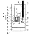
図7は本実施例に係るAu−Snろう付け用インサート材の断面図であり、図中、701は、ガス溜め穴(貫通穴)702を多数あけた厚さの一様なSUS304板(インサート材)で、このインサート材701の表面にろう材層502が形成してある。ろう材層502は、インサート材の母材(SUS304板)701側から順に積層された厚さ0.3μmのNiめっき(下地めっき)、厚さ3μmのAuめっき、厚さ3μmのSnめっき、厚さ0.5μmのAuめっきの4層からなる。
【0048】
本実施例においても、上記めっき層のうち、少なくとも1種類のめっき皮膜内に0℃、1気圧換算でめっき体積の1/2以上の水素あるいは水を含ませている。
【0049】
図8により本実施例の接合プロセスを説明する。
【0050】
図8は、本実施例におけるAu−Snろう付け用インサート材を用いて2つの部材を接合する方法を示し、図中、803及び804は、SUS304製の被接合部材、805は厚さ0.3μmのNiめっき、806は厚さ0.5μmのAuめっき、807aは接合プロセス途中のAu−Sn−Ni合金融液、807bは凝固したAu−Sn−Ni合金、808は気泡である。
【0051】
接合プロセスは次のとおりである。
(1)まず被接合部材803及び804の間に図7にて詳細を示したAu−Snろう付け用インサート材701を挿入する〔図8(a)〕。
(2)次に接合面を密着させ、N2雰囲気中で360℃に加熱する。ろう材層502とNiめっき805及びAuめっき806が共晶反応を生じて溶融し、Au−Sn−Ni合金融液807aを形成する〔図8(b)〕。この際、ろう材層502からのアウトガスによりAu−Sn−Ni合金融液807a中に気泡808が形成される。これらの気泡808のうち、接合部外周に近いものは、そのまま接合部外に放出されるが、接合部外周から離れているものはインサート材(SUS304板)701に設けられたガス溜め穴702に捕捉されることにより、Au−Sn−Ni合金融液外に放出される。この作用により、被接合部材が微小でなくとも、接合部から気泡808を除去することが可能である。接合部を冷却することにより、符号の807bに示すようにAu−Sn−Ni合金融液は凝固し〔図8(c)〕、被接合部材803及び804はAu−Sn−Ni合金807bにより強固に接合される。
【0052】
図9を用いて上記第4実施例に適用するSUS304板にあけられた穴の寸法及び配置の例を説明する。901はAu−Snろう付け用インサート材、902、903、904はガス溜め用の穴である。
【0053】
図9(a)に示す例では穴902は円形、(b)に示す実施例では穴903は矩形、(c)に示す実施例では穴904は不定形である。これらに示すごとく、穴は任意の形状とすることができる。これらの穴の直径はAu−Snろう付け用インサート材901の厚さの1/2倍以上、望ましくは1倍以上、さらに望ましくは2倍以上、さらに望ましくは3倍以上とする。また穴のピッチは、直径5mm以下、望ましくは3mm以下、さらに望ましくは2mm以下の円内に1個以上の穴が位置する値とする。このように穴を配置することにより、ろう材層502から生じたガスによる気泡を有効に捕捉することができ、強固な接合部を得ることができる。
【0054】
〔実施例5〕
本発明の第5実施例を図10及び図11を用いて説明する。
【0055】
図10は本実施例に係るAu−Snろう付け用インサート材の断面図で、図中、1001は穴のない厚さの一様なSUS304板(インサート材)、1102は、インサート材1001上に部分的に形成されたろう材層で、ろう材層1102は、母材1001側から順に厚さ0.3μmのNiめっき、厚さ3μmのAuめっき、厚さ3μmのSnめっき、厚さ0.5μmのAuめっきの4層からなり、部分的に形成されたろう材層1102が多数、間隔1109を置いて縞状或いは格子状に形成されている。
【0056】
本実施例においても、少なくとも1種類のめっき皮膜内に0℃、1気圧換算でめっき体積の1/2倍以上の水素あるいは水を含ませている。
【0057】
図11により、本実施例におけるAu−Snろう付け用インサート材を用いて2つの部材を接合するプロセスを説明する。
【0058】
図11において、1103及び1104は、SUS304製の被接合部材、1105は部分的に施された厚さ0.3μmのNiめっき、1106はNiめっき1105上に形成された厚さ0.5μmのAuめっき、1107aはAu−Sn−Ni合金融液、1107bは凝固したAu−Sn−Ni合金、1108は気泡である。
【0059】
接合プロセスは次のとおりである。
(1)まず被接合部材1103及び1104の間に、図10にて詳細を示したAu−Snろう付け用インサート材を挿入する〔図11(a)〕。
(2)次に接合面を密着させ、N2雰囲気中で360℃に加熱する。ろう材層1102とNiめっき1105及びAuめっき1106が反応を生じて溶融し、Au−Sn−Ni合金融液1107aを形成する〔図11(b)〕。この際、ろう材層1102からのアウトガスによりAu−Sn−Ni合金融液1107a中に気泡1108が形成される。これらの気泡1108は、周囲のろう材層502が形成されていない部分(間隙)1109を通じて接合部外に放出される。この効果により被接合部材が微小でなくとも、接合部から気泡1108を除去することが可能である。
【0060】
次に接合部を冷却することにより、Au−Sn−Ni合金融液は符号1107bに示すように凝固し、被接合部材1103及び1104はAu−Sn−Ni合金1107bにより強固に接合される。
【0061】
SUS304製の被接合材1103および1104は、Au−Sn−Ni合金融液1107aにぬれないので、Au−Sn−Ni合金融液1107aは部分的に施されたNiめっき1105の外部に広がることはない。したがってAu−Sn−Ni合金融液1107aがぬれなかった部分には空間1109が確保される。この空間部分は流体を導く流路として利用することができる。
【0062】
さらにSUS304製の被接合材1103および1104を、電気回路が形成された基板あるいは電子デバイスとすることにより、凝固したAu−Sn−Ni合金1107bを電極兼電子デバイス固定用構造材料として用いることが可能である。
【0063】
〔実施例6〕
本発明の第6実施例を図12、図13及び図14を用いて説明する。本実施例は、上記各実施例の接合方式の一例として、インクジェットプリンタへの適用例を示すものである。
【0064】
図12は本実施例のインクジェットプリンタの断面である。1201は筐体、1202はメモリーカード、1203は制御基板、1204は紙送りベルト、1205は用紙、1206は用紙受け、1207はプリントヘッド、1208はインクローダ、1209はインクカセット、1210は用紙カセット、1211はヘッド送りモータ、1212は用紙ピックアップローラ、1213はヘッドキャリッジ、1214は紙送りモータ、1215は電源、1216は液体インク、1217は固体インク、1218はインク溶融用のヒータ、1219は印字ノズルである。
【0065】
ここで、本例のインクジェットプリンタの動作を説明する。
【0066】
まず用紙カセット1210に用紙1205をセットする。用紙は200枚までセット可能である。図示しないコンピュータより印字信号が送られると、印字信号はメモリーカード1202内に一時的に記憶され、制御基板に実装されたマイクロコンピュータにより印刷イメージに展開される。印刷イメージができあがると、用紙1205は用紙ピックアップローラ1212によりピックアップされ、印刷所定位置まで紙送りモータ1214及び紙送りベルト1204により送られる。ついで用紙1205の位置を紙送りベルト1204で制御し、ヘッドキャリッジ1213を介してヘッド送りモータ1211にてプリントヘッドの位置を制御しつつ、プリントヘッド1207の先端に取り付けられた印字ノズルよりインクを噴射して印字を行う。プリントヘッド内のインクの量がある一定量以下となると、インクローダにより自動的にインクカセット1209内に蓄えられている固体インク1217が供給される。固体インク1217はプリントヘッド内のヒータ1218により供給される熱により溶融し、液体インク1216となる。上述の全ての動作は制御基板1203により制御される。また印字動作に必要な全ての電力は電源1215により供給される。
【0067】
図13により印字ノズル1219の詳細を示す。
【0068】
このうち、1310は厚さ0.3μmのNiめっき及び厚さ0.5μmのAuめっきが施されたアルミニウム製ハウジングホルダであり、このアルミニウム製ハウジングホルダ1310には、インク流路1311及び1312、PZTアクチュエータ1313が配設されている。
【0069】
1320はインサート材となるSUS304製ボンディングプレートで、このボンディングプレート1320は、母材側から順に厚さ0.3μmのNiめっき、厚さ2.5μmのAuめっき、厚さ3μmのSnめっき、厚さ0.5μmのAuめっきの4層よりなるろう材層が形成されている。
【0070】
このボンディングプレート1320には、PZTアクチュエータ用穴1322が設けてある。
【0071】
1330はNi合金製ダイアフレームフィルタープレートで、このダイアフレームフィルタープレート1330の表面には、厚さ0.3μmのNiめっき及び厚さ0.5μmのAuめっきが施されている。
【0072】
また、ダイアフレームフィルタープレート1330には、フィルターメッシュ1331が形成されている。
【0073】
1340はSUS304製リストリクタープレートで、その表面には、厚さ0.3μmのNiめっき、厚さ2.5μmのAuめっき、厚さ3μmのSnめっき、厚さ0.5μmのAuめっきよりなるろう材層が施されている。
【0074】
リストリクタープレート1340には、リストリクター1341が設けてある。
【0075】
1350はNi合金製オリフィスプレートで、その表面には、厚さ0.3μmのNiめっき及び厚さ0.5μmAuめっきが施されている。オリフィスプレート1350には、オリフィス1351が配設されている。
【0076】
1360はインク通過経路、1370はインク、1314、1323、1332、1342及び1352は組み立て時の位置決め穴、1315、1324、1333、1343及び1353はプリントヘッドへの取り付け用ボルトの通し穴、1325及び1344は直径0.15mmの穴である。
【0077】
これらを位置決め穴と位置決めピンを用いて、図14に示すように、アルミニウム製ハウジングホルダ1310、ボンディングプレート1320、ダイアフレームフィルタプレート1330、リストリクタープレート1340、オリフィスプレート1350を位置決めして重ね合わせ、N2雰囲気中で60秒間、360℃の加熱及び120kgfの加圧を行い接合する。
【0078】
ボンディングプレート1320及びリストリクタープレート1340には、接合時にAu−Sn合金から放出されるガスを逃がす穴1325及び1344が一面に開けられており、各部品を強固に接合することができる。
【0079】
接合されたノズル内には微細なインク流路が形成される。プリントヘッドから供給されたインクはインク流路1311に流入し、インク通過経路1360に沿ってボンディングプレート3120を通過し、ダイアフレームフィルタープレート1330に形成されたフィルターメッシュ1331にて異物をろ過し、リストリクタープレート1340に形成されたリストリクター1341に流入する。次にPZTアクチュエータ1313がボンディングプレート1320に形成されたPZTアクチュエータ用穴を通してダイアフレームフィルタープレート1330を変位させることによりリストリクター部に蓄えられたインク1370に圧力を加える。インク1370はその反動でオリフィスプレートに形成されたオリフィス1351から勢いよく噴出し、印字にあずかる。
【0080】
図14を用いて印字ノズル1219の接合部構造を説明する。1410は、厚さ0.3μmのNiめっき及び0.5μmAuめっきからなるめっき層、1420は、厚さ0.3μmのNiめっき、厚さ2.5μmのAuめっき、厚さ3μmSnめっき及び厚さ0.5μmのAuめっきからなるろう材層、1421はガス溜め、1430はAu−Sn−Ni合金からなるろう材、1450はエポキシ接着剤である。
【0081】
接合プロセスは次のとおりである。まず被接合部材1310、1320、1330、1340及び1350を重ね合せる。次に接合面を密着させ、N2雰囲気中で360℃に加熱する。ろう材層1420とめっき層1410が反応を生じて溶融し、Au−Sn−Ni合金融液を形成する。この際、ろう材層1420からのアウトガスによりAu−Sn−Ni合金融液中に気泡が形成されるが、これらの気泡は周囲のガス溜め1421に吸収され、接合部から除去される。接合部を冷却することによりAu−Sn−Ni合金融液は凝固して固相のろう材1430となり、各部材は強固に接合される。次にPZT1440をエポキシ接着剤1450を用いてダイアフレームプレート1330に接着する。
【0082】
プリントヘッドから供給されたインクは、インク流路1311に流入し、インク通過経路1360に沿ってボンディングプレート1320を通過し、ダイアフレームフィルタープレート1330に形成されたフィルターメッシュ1331にて異物をろ過され、リストリクタープレートに形成されたリストリクター1341に流入する。次にPZTアクチュエーター1313がボンディングプレート1320に形成されたPZTアクチュエーター用穴を通してダイアフレームフィルタープレート1330を変位させることによりリストリクター部に蓄えられたインク1370に圧力を加える。インク1370はその反動でオリフィスプレートに形成されたオリフィス1351から勢いよく噴出し、印字にあずかる。
【0083】
なお、被接合部材同士を接合する場合において、それらのめっきの厚さは、上記実施例に限定されるものではなく、例えば、母材側から順に厚さ0.5μm以下のNiめっき、厚さ5μm以下のAuめっき、厚さ5μm以下のSnめっき、厚さ5μm以下のAuめっきを層状に施したもの、
或いは、上記のような層状めっきを施した金属部材との接続対象として、母材側から順に厚さ0.5μm以下のNiめっき、厚さ0.5μm以下のAuめっきを層状に施したものであれば、本発明の所期の効果を奏することができる。
【0084】
本実施例によれば、インク噴射ノズルを構成している各部品をAu−Sn合金にて接続しているので、有機接着剤を用いて接合した場合よりも経時劣化が少なく、信頼性の高い接合を行うことができる。
【0085】
また、Au−Sn合金は酸及びアルカリに対する耐食性に優れており、高温下で腐食性を有するインクでも用いることができ、インク設計の自由度が増加する。その結果、良好な印字特性を有するインクの開発が容易となる効果がある。
【0086】
なお、上記実施例では各部品の材料をSUS304、Ni合金及びアルミニウムとしているが、一般の鉄鋼や銅合金など、Au−Sn共晶温度の280℃の加熱に耐える材料であればよい。またAuめっきの下地めっきとしてNiめっきを用いているが、Cuめっきでも同様の効果を得ることができる。また接合雰囲気はN2のみでなく、Ar等の非酸化性雰囲気中にても同様に接合を行なうことができる。
【0087】
【発明の効果】
本発明によれば、
(イ)接合プロセスにおいて、めっき皮膜内に水素あるいは水を含ませておくことにより、接合時の加熱により水素あるいは水がガス化して、このガス(気泡)が接合外部流出に際して、溶融したAu−Sn合金を攪拌しAu−Sn合金を撹拌することができ、しかも、Au−Snの重量配分を、下地のNiめっき及びプロセス中に生じるNi−Au−Sn化合物との反応を考慮して定めてあるので、そのプロセスで接合強度が高い接合方法を提供することができる。さらに、耐食性を配慮して被接合部材の下地めっきとしてNiめっきを施すが、このNiめっきの厚さを0.5μm以下とすることにより、接合中にNiめっきはAu−Sn合金融液中に完全に溶解し、接合界面に残留しないので強固な接合をより助長する。
【0088】
(ロ)Au−Sn合金を箔としてではなく、めっき皮膜の形態で供給するので、従来のような機械加工によるAu−Sn箔を製作する工程をなくし、製作コス
トの低減を図り得る。
【0089】
(ハ)接合前の接合表面はAuであり、Auが酸化しないことからフラックスを用いなくとも接合部を一体化させることが可能になり、従来のようなフラックス除去作業をなくし作業効率を高めると共に、残留フラックスによる接合部の
腐食といった問題をなくし、接合部の耐食性を高めることができる。
【0090】
(ニ)また、本発明の接合法は、接合材の加熱温度も高融点ろう材に比較して低くできるので、熱による部材の変形も少ない。Au−Sn合金は耐食性に優れるので、腐食性の強いインクによっても腐食されることがない。特に、インクジェットの噴射ノズルを構成している各部品をAu−Sn合金にて接続した場合には、有機接着剤を用いて接合した場合よりも経時劣化が少なく、信頼性の高い接合を行うことができる。
【0091】
またAu−Sn合金は酸及びアルカリに対する耐食性に優れており、高温下で腐食性を有するインクでも用いることができ、インク設計の自由度が増加する。その結果良好な印字特性を有するインクの開発が容易となる効果がある。
【図面の簡単な説明】
【図1】本発明の第1実施例に係る接合プロセスを示す断面図。
【図2】ピール強度とNi−Au−Sn金属間化合物の厚さとの関係を示す線図。
【図3】Au−Sn2元系の状態説明図。
【図4】本発明の第2実施例に係る接合プロセスを示す断面図。
【図5】本発明の第3実施例に係るAu−Snろう付け用インサート材の断面図。
【図6】上記Au−Snろう付け用インサート材を用いて2つの部材を接合するプロセスを示す断面図。
【図7】本発明の第4実施例に係るAu−Snろう付け用インサート材の断面図。
【図8】上記第4実施例のAu−Snろう付け用インサート材を用いて2つの部材を接合するプロセスを示す断面図。
【図9】第4実施例に用いるインサート材にあけられた穴の寸法及び配置の例を示す平面図。
【図10】本発明の第5実施例に係るAu−Snろう付け用インサート材の断面図。
【図11】上記第5実施例のAu−Snろう付け用インサート材を用いて2つの部材を接合するプロセスを示す断面図。
【図12】本発明の適用対象となるインクジェットプリンタ(第6実施例)の断面図。
【図13】上記インクジェットプリンタに用いる印字ノズルの詳細構造を示す分解斜視図。
【図14】上記印字ノズルの接合プロセスを示す説明図。
【符号の説明】
101…SUS304板(母材)、102…Niめっき、103…Auめっき、104…Snめっき、105…Auめっき、106a…Au−Sn合金融液、106b…Au−Sn合金、107…Ni−Au−Sn金属間化合物、401a、401b…SUS304板、402a、402b…Niめっき、403a…Auめっき、404a…Snめっき、405a、405b…Auめっき、406a…Au−Sn合金融液、406b…Au−Sn合金、407a…Ni−Au−Sn金属間化合物、407b…Ni−Au−Sn金属間化合物、501…SUS304板、502…ろう材層(Niめっき、Auめっき、Snめっき、Auめっき)、503及び504…被接合部材、505…Niめっき、506…Auめっき、507a…Au−Sn−Ni合金融液、507b…Au−Sn−Ni合金、508…気泡、701…穴付きSUS304板、702…ガス溜めの穴、502…ろう材層(Niめっき、Auめっき、Snめっき、Auめっき)、803、804…被接合部材、805…Niめっき、806…Auめっき、807a…Au−Sn−Ni合金融液、807b…凝固したAu−Sn−Ni合金、808…気泡、901…Au−Snろう付け用インサート材、902、903及び904…穴、1001…SUS304板、502…ろう材層(Niめっき、Auめっき、Snめっき、Auめっき)、1103、1104…SUS304(被接合部材)、1105…Niめっき、1106…Auめっき、1107a…Au−Sn−Ni合金融液、1107b…Au−Sn−Ni合金、808…気泡、1207…プリントヘッド、1410…Niめっき・Auめっきの層)、1420…ろう材層(Niめっき・Auめっき・Snめっき・Auめっきの層)、1421…ガス溜め、1430…Au−Sn−Ni合金からなるろう材、1450…エポキシ接着剤。[0001]
[Industrial applications]
The present invention uses an Au-Sn alloy (containing an underlying plating component such as Ni and Cu and containing a small content of an Au-Sn-Ni alloy and an Au-Sn-Cu component) to connect metal members to each other. The present invention relates to a method of joining by brazing, an insert material for Au-Sn brazing, and an ink jet printer using these joining techniques.
[0002]
[Prior art]
Conventionally, when brazing metal members using an Au-Sn alloy, a flux having an action of removing an Au-Sn alloy foil and an oxide film on a bonding surface is inserted into a bonding portion and heated and pressed. Had been attached. Other joining methods include bonding of print head components of an ink jet printer with an organic adhesive or a high melting point brazing filler such as Ni-P brazing or Au-Ni brazing as disclosed in JP-A-2-107451. It was joined using materials.
[0003]
[Problems to be solved by the invention]
When the Au-Sn alloy foil and the flux are inserted into the joint at the time of the Au-Sn brazing, the flux has a corrosive property, so that a step of cleaning and removing the residual flux is required. Further, there is a problem that the flux that is caught in the solder and remains at the joints corrodes the joints. In addition, since the Au-Sn alloy has almost no ductility, it cannot be rolled. In order to form a foil, it is necessary to thinly process a plate-shaped ingot by grinding.
[0004]
On the other hand, when an organic adhesive is used for joining the print heads, the adhesive strength decreases due to the aging of the adhesive, and it has been difficult to increase the reliability of the joint. Further, when a high melting point brazing material is used, it is difficult to improve the joining accuracy because members to be joined are plastically deformed due to a decrease in yield strength due to a high temperature and thermal strain.
[0005]
The present invention has been made in view of the above points, and has as its object to solve the problems of Au-Sn alloy foil, flux, organic adhesive, and high melting point brazing material as described above, and to substitute Au-Sn alloy bonding It is an object of the present invention to provide a highly reliable joining technique that has high joining strength, high corrosion resistance, and excellent joining accuracy by using a technique and devising the joining conditions.
[0006]
[Means for Solving the Problems]
The present invention first proposes the following joining method.
[0007]
That is, a base plating (for example, Ni plating) having a thickness of 0.5 μm or less, an Au plating having a thickness of 5 μm or less, a Sn plating having a thickness of 5 μm or less, and an Au plating having a thickness of 5 μm or less were sequentially formed in layers from the base material side. Metal parts
Alternatively, the metal member on which the layer plating is applied, the metal member on which a base plating having a thickness of 0.5 μm or less and an Au plating having a thickness of 0.5 μm or less are layered in order from the base material side are subjected to vacuum or inactive. Joining by heating and pressurizing in gas,
And as joining conditions,
The composition in the system of the Au plating and the Sn plating excluding the base plating is such that Sn is more than 20 mass% and less than 40 mass% in the entire plating combination to be laminated,
The Au plating and the Sn plating are characterized by using wet plating including at least one of hydrogen and water in a plating film at a temperature of 0 ° C. and a pressure of 1/2 atmosphere or more in terms of plating volume. The first invention).
[0008]
Further, in the method of joining the members to be joined to each other via a brazing insert material, the surface of the base material of the insert material is subjected to base plating, and Au plating and Sn plating are applied thereon in layers. We propose an Au-Sn brazing insert material in which at least one type of plating layer contains hydrogen or water in an amount of 1/2 or more times the plating volume in terms of 0 ° C. and 1 atm. The second invention).
[0009]
[Action]
According to the first aspect, in the joining step, when the members to be joined are heated while being pressurized, Au and Sn cause a eutectic reaction to melt (melt). In this case, at least Au plating and Sn plating are H 2 It contains a large amount of gas and moisture, and these gases become bubbles by heating and are released from the Au-Sn melt into the heated atmosphere. At the time of this gas release, the bubbles stir the Au-Sn melt and break and destroy the contaminant layer remaining in the Au-Sn melt, so that the Au-Sn melt is completely integrated.
[0010]
In the joining process, a Ni-Au-Sn compound, which is a reaction product of the Au-Sn melt and the base plating (here, Ni plating), is formed at the interface. This intermetallic compound has a low strength and is a factor in lowering the bonding strength. However, if the heating is further continued in the above-mentioned thickness setting (quantitative setting) of the plating, the thickness of the Ni plating as the base plating is reduced to 0.1. By setting the thickness to 5 μm or less, the Ni plating and the Ni—Au—Sn intermetallic compound are completely dissolved in the Au—Sn melt to eliminate the above-described element of lowering the bonding strength. Contact directly with liquid. Then, when cooled, the joint becomes an Au-Sn alloy containing a small amount of Ni, whereby the members to be joined (metal members) are firmly joined.
[0011]
The eutectic point of the Au-Sn binary system is Au-20 mass% Sn, but in the process of dissolving Ni in the Au-Sn melt, Ni and Sn react to form an intermetallic compound, The Sn content in the Au-Sn melt decreases accordingly. When Sn decreases from the eutectic point, the melting point of the Au-Sn alloy sharply increases.
[0012]
For example, when the Au-Sn melt at the initial stage of joining has a eutectic composition, it is completely in a liquid phase when heated to 633 K. Here, when Sn is consumed by the reaction with Ni, the Au-Sn melt becomes , The melting point rises. When the Sn concentration decreases, the melting point of the Au—Sn melt becomes equal to the heating temperature and solidifies isothermally. Once solidified, the dissolution rate of Ni into the Au-Sn alloy is extremely reduced, and it takes an extremely long time to completely dissolve Ni into the Au-Sn alloy. Therefore, in order to continue melting the Au-Sn alloy until the Ni is completely dissolved, the Sn concentration of the initial Au-Sn melt should be set to more than 20 mass% and 30 mass% or less in consideration of the reaction with Ni. Preferably, it is preferably from 22 mass% to 29 mass%, more preferably from 24 mass% to 28 mass%.
[0013]
When joining members to be joined using the Au-Sn brazing insert material of the second invention, the following is performed.
[0014]
An Au-Sn brazing insert material is inserted between the members to be joined, and the joining surfaces are brought into close contact and heated. The Au plating and Sn plating on the insert material side cause eutectic reaction and melt (in this case, Au plating is also applied to the base material surface on the member to be joined side, and the Au plating and the Au plating and Sn on the insert material side are performed). The plating may be melted together).
[0015]
In the present invention, H 2 The gas (bubbles) resulting from the gas and moisture agitates the Au-Sn melt, and the joint finally becomes an Au-Sn alloy containing a small amount of Ni or an Au-Sn-Ni having a small Ni content ratio. It becomes an alloy. Therefore, by using this brazing insert material, the members to be joined are firmly joined to each other.
[0016]
【Example】
[Example 1]
A first embodiment of the present invention will be described with reference to FIG.
[0017]
FIG. 1 shows, in order from the base material side, metal members formed with a 0.3 μm-thick Ni plating, a 3 μm-thick Au plating, a 3 μm-thick Sn plating, and a 0.5 μm-thick Au plating. N 2 It is a figure showing the lamination joining method of joining by heating and pressurizing in gas.
[0018]
101 is a SUS304 plate (base material) having a thickness of 50 μm, 102 is Ni plating having a thickness of 0.3 μm (base plating for achieving corrosion resistance of the base material), 103 is Au plating having a thickness of 3 μm, and 104 is 3 μm. Sn plating of 105, Au plating of thickness 0.5 μm, 106a Au-Sn alloy liquid generated by eutectic reaction of Au and Sn, 106b Au-Sn alloy solidified from the melt,
[0019]
Next, the joining process will be described.
[0020]
First, as joining conditions,
{Circle around (1)} The composition of the system of the Au plating 103, 105 excluding the Ni plating 102 and the Sn plating 104 is set to be more than 20 mass% and less than 40 mass% of Sn in the entire plating combination with respect to the Au plating.
{Circle around (2)} For each of the
[0021]
Under the above conditions,
(1) The SUS304 plate (metal member to be joined) 101 on which the above-described four layers of plating 102 to 105 are applied is placed facing each other, and the atmosphere is set to N. 2 Replace with gas [FIG. 1 (a)].
[0022]
(2) When the metal member to be joined is heated to 360 ° C. while pressurizing, Au and Sn in the plating layer cause a eutectic reaction and dissolve to form an Au—Sn melt 106 a (FIG. 1B). ]. Each plating film is H 2 It contains a large amount of gas and moisture, and these gases are released by heating. The released gas becomes
[0023]
The relationship between the peel strength and the thickness of the Ni-Au-Sn intermetallic compound in joining the SUS304 plates will be described with reference to FIG. In FIG. 2, the abscissa indicates the thickness d obtained by combining the intermetallic compound and the Ni plating, and the ordinate indicates the peel strength. The peel strength tends to increase as d decreases. It can be seen that the highest strength is obtained when d is 0, that is, when Ni is completely dissolved in the Au-Sn melt.
[0024]
FIG. 3 shows a state diagram of the Au—Sn binary system. The eutectic point of the Au-Sn binary system is Au-20 mass% Sn, which is shown as point A in the figure. In the process of dissolving Ni in the Au-Sn melt, Ni and Sn react to form an intermetallic compound, and the Sn content in the Au-Sn melt decreases accordingly. It is shown in the phase diagram that when Sn decreases from the eutectic point, the melting point of the Au-Sn alloy sharply increases.
[0025]
For example, when the Au-Sn melt in the early stage of joining has a eutectic composition, when heated to 633K, the position in the phase diagram becomes point A, indicating that it is completely in the liquid phase. Here, when Sn is consumed by the reaction with Ni, the Sn concentration in the Au—Sn melt decreases and the melting point increases. When the Sn concentration decreases and reaches the point A ′, the melting point of the Au—Sn melt becomes equal to the heating temperature and solidifies isothermally. Once solidified, the dissolution rate of Ni into the Au-Sn alloy is extremely reduced, and it takes an extremely long time to completely dissolve Ni into the Au-Sn alloy. Therefore, in order to continue melting the Au-Sn alloy until the Ni is completely dissolved, the Sn concentration of the initial Au-Sn melt should be set to more than 20 mass% and 30 mass% or less in consideration of the reaction with Ni. Preferably, it is preferably from 22 mass% to 29 mass%, more preferably from 24 mass% to 28 mass%.
[0026]
According to the present embodiment, the following effects can be obtained.
(A) As described above, in the bonding process, the Au—Sn alloy can be stirred, and the weight distribution of Au—Sn is determined by the Ni plating of the base and the reaction with the Ni—Au—Sn compound generated during the process. It is determined in consideration of
Thus, a joining method having a high joining strength can be provided.
(B) Since the Au-Sn alloy is supplied not in the form of a foil but in the form of a plating film, the step of manufacturing the Au-Sn foil by conventional machining is eliminated, and the production cost is reduced.
Can be reduced.
(C) The bonding surface before bonding is Au, and since the Au is not oxidized, it is possible to integrate the bonded portion without using a flux, thereby eliminating the conventional flux removing work and improving the work efficiency. , Residual flux
The problem of corrosion can be eliminated, and the corrosion resistance of the joint can be improved.
[0027]
[Example 2]
A second embodiment of the present invention will be described with reference to FIG.
[0028]
In the present embodiment, a metal member formed with Ni plating of 0.3 μm thickness, Au plating of 3 μm thickness, Sn plating of 2.5 μm thickness, and Au plating of 0.5 μm thickness in order from the base material side, A metal member formed with a 0.3 μm-thick Ni plating and a 0.5 μm-thick Au plating is laminated, and N 2 It is a figure showing the lamination joining method of joining by heating and pressurizing in gas.
[0029]
401a and 401b are SUS304 plates having a thickness of 50 μm to be base materials (members to be joined), 402a and 402b are Ni plating (base plating) having a thickness of 0.3 μm, 403a is Au plating having a thickness of 2.5 μm, 404a is a Sn plating with a thickness of 3 μm, 405a and 405b are Au platings with a thickness of 0.5 μm, 406a is an Au-Sn alloy solution produced by a eutectic reaction between Au and Sn, and 406b is a solidified Au-Sn The alloy, 407a is a Ni-Au-Sn intermetallic compound formed by the reaction between the Au-Sn
[0030]
Next, the joining process will be described.
[0031]
In this example, the bonding conditions (1) and (2) are the same as in the first embodiment, that is, the composition of the system of the Au plating 403a, 405a, 405b excluding Ni plating and the Sn plating 404a is changed to the entire plating combination to be laminated. And Sn is more than 20 mass% and less than 40 mass%,
Further, for each of the
[0032]
Under the above joining conditions,
(1) The members to be joined (the
(2) These metal members to be joined are heated to 360 ° C. while slightly applying pressure. Au and Sn undergo a eutectic reaction and dissolve. In this case, unlike the embodiment described with reference to FIG. 1, the Au plating 405b on the
[0033]
Each plating film is H 2 It contains a large amount of gas and moisture, and these gases are released by heating. The released gas is released as bubbles into the Au-Sn melt 406a into the atmosphere. At this time, the gas bubbles 408 agitate the Au—Sn melt 406a and break and destroy the
[0034]
At the interface between the Au-Sn melt 406a and the Ni platings 402a and 402b, Ni-Au-
[0035]
When the Au-Sn melt 406a at the initial stage of joining has a eutectic composition, as described above, the Sn concentration in the Au-Sn melt 406a decreases due to the reaction between Sn and Ni, and the melting point increases. The Au-Sn melt 406a solidifies isothermally. Once solidified, the dissolution rate of Ni in the Au-Sn alloy is extremely reduced, and it takes an extremely long time to completely dissolve the Ni platings 402a and 402b in the Au-Sn alloy. Therefore, in order to keep melting the Au-Sn alloy until the Ni platings 402a and 402b are completely melted, the Sn concentration of the initial Au-Sn melt 406a is increased from 20 mass% to 30 mass% in consideration of the reaction with Ni. The content is preferably as follows, preferably from 22 mass% to 29 mass%, and more preferably from 24 mass% to 28 mass%. In the case of the present embodiment, the initial Sn concentration of the Au-Sn melt 406a needs to be calculated in consideration of the amount of the Au plating 405b in the plating films 403a, 404a, and 405a.
[0036]
According to this embodiment, the same effects as those of the first embodiment can be obtained.
[0037]
[Example 3]
A third embodiment of the present invention will be described with reference to FIGS.
[0038]
This embodiment is an example in which members to be joined are joined to each other via an Au-Sn brazing insert material, unlike the above embodiments. FIG. 5 is a longitudinal sectional view of the insert material, and FIG. 3 shows a joining process.
[0039]
[0040]
This embodiment is the most basic embodiment of the Au-Sn brazing insert material. This embodiment is suitable for brazing a minute part. By using the
[0041]
The joining process of this embodiment will be described with reference to FIG.
[0042]
[0043]
Regarding the bonding conditions, also in the present embodiment, at least one type of plating film among the above-mentioned plating layers contains hydrogen or water in an amount of 1/2 or more of the plating volume in terms of 0 ° C. and 1 atm.
[0044]
The joining process is as follows.
(1) First, an Au-Sn brazing insert made of a
(2) Next, the joining surfaces of the members to be joined 503 and 504 and the insert material are brought into close contact with each other, and N 2 Heat to 360 ° C. in atmosphere. The
[0045]
According to this embodiment, in addition to having the same effects as those of the first and second embodiments, by applying most of the plating layer for bonding to the insert material side, it is possible to broaden the application target of the member to be bonded. Can be.
[0046]
[Example 4]
A fourth embodiment of the present invention will be described with reference to FIGS.
[0047]
FIG. 7 is a cross-sectional view of an Au-Sn brazing insert material according to the present embodiment. In the drawing,
[0048]
Also in this embodiment, at least one kind of plating film among the above-mentioned plating layers contains hydrogen or water in an amount of 1/2 or more of the plating volume in terms of 0 ° C. and 1 atm.
[0049]
The joining process of this embodiment will be described with reference to FIG.
[0050]
FIG. 8 shows a method of joining two members using an Au-Sn brazing insert material in the present embodiment. In the drawing,
[0051]
The joining process is as follows.
(1) First, an Au-Sn
(2) Next, the bonding surfaces are brought into close contact, and N 2 Heat to 360 ° C. in atmosphere. The
[0052]
An example of the size and arrangement of the holes formed in the SUS304 plate applied to the fourth embodiment will be described with reference to FIG. 901 is an Au-Sn brazing insert material, and 902, 903 and 904 are holes for gas reservoirs.
[0053]
In the example shown in FIG. 9A, the
[0054]
[Example 5]
A fifth embodiment of the present invention will be described with reference to FIGS.
[0055]
FIG. 10 is a cross-sectional view of an Au-Sn brazing insert material according to the present embodiment. In the drawing, reference numeral 1001 denotes a SUS304 plate (insert material) having a uniform thickness without holes, and 1102 denotes an insert material on the insert material 1001. In the brazing material layer formed partially, the
[0056]
Also in this embodiment, at least one type of plating film contains hydrogen or water in an amount of 1/2 or more times the plating volume in terms of 0 ° C. and 1 atm.
[0057]
Referring to FIG. 11, a process of joining two members using the Au-Sn brazing insert material in the present embodiment will be described.
[0058]
In FIG. 11,
[0059]
The joining process is as follows.
(1) First, an Au-Sn brazing insert material shown in detail in FIG. 10 is inserted between the members to be joined 1103 and 1104 [FIG. 11 (a)].
(2) Next, the bonding surfaces are brought into close contact, and N 2 Heat to 360 ° C. in atmosphere. The
[0060]
Next, by cooling the joint, the Au-Sn-Ni alloy liquid solidifies as indicated by
[0061]
Since the materials to be joined 1103 and 1104 made of SUS304 are not wetted by the Au—Sn—Ni combined liquid 1107a, the Au—Sn—Ni combined liquid 1107a cannot spread outside the partially applied Ni plating 1105. Absent. Therefore, a
[0062]
Further, by using the
[0063]
[Example 6]
A sixth embodiment of the present invention will be described with reference to FIGS. This embodiment shows an example of application to an ink jet printer as an example of the joining method of each of the above embodiments.
[0064]
FIG. 12 is a cross section of the ink jet printer of the present embodiment. 1201 is a housing, 1202 is a memory card, 1203 is a control board, 1204 is a paper feed belt, 1205 is a paper, 1206 is a paper receiver, 1207 is a print head, 1208 is an ink loader, 1209 is an ink cassette, 1210 is a paper cassette, 1211 is a head feed motor, 1212 is a paper pickup roller, 1213 is a head carriage, 1214 is a paper feed motor, 1215 is a power supply, 1216 is liquid ink, 1217 is solid ink, 1218 is a heater for melting ink, and 1219 is a print nozzle. is there.
[0065]
Here, the operation of the ink jet printer of this embodiment will be described.
[0066]
First, the
[0067]
FIG. 13 shows the details of the
[0068]
Among them, 1310 is an aluminum housing holder on which a 0.3 μm-thick Ni plating and a 0.5 μm-thick Au plating have been applied. The
[0069]
[0070]
The
[0071]
[0072]
Further, a
[0073]
[0074]
The
[0075]
[0076]
1360 is an ink passage path, 1370 is ink, 1314, 1323, 1332, 1342, and 1352 are positioning holes at the time of assembly, 1315, 1324, 1333, 1343, and 1353 are through holes for mounting bolts to the print head, 1325 and 1344. Is a hole having a diameter of 0.15 mm.
[0077]
Using an alignment hole and an alignment pin, as shown in FIG. 14, an
[0078]
[0079]
A fine ink flow path is formed in the joined nozzles. The ink supplied from the print head flows into the
[0080]
The joint structure of the
[0081]
The joining process is as follows. First, the members to be joined 1310, 1320, 1330, 1340, and 1350 are overlapped. Next, the bonding surfaces are brought into close contact, and N 2 Heat to 360 ° C. in atmosphere. The
[0082]
The ink supplied from the print head flows into the
[0083]
In the case of joining the members to be joined, the thickness of the plating is not limited to the above-described embodiment, for example, Ni plating having a thickness of 0.5 μm or less in order from the base material side. Au plating of 5 μm or less, Sn plating of 5 μm or less in thickness, Au plating of 5 μm or less in a layered form,
Alternatively, as an object to be connected to a metal member that has been subjected to layer plating as described above, Ni plating having a thickness of 0.5 μm or less and Au plating having a thickness of 0.5 μm or less are sequentially applied from the base material side in layers. If so, the desired effects of the present invention can be achieved.
[0084]
According to the present embodiment, since the components constituting the ink jet nozzle are connected by the Au-Sn alloy, the deterioration with time is less than that in the case of joining using the organic adhesive, and the reliability is high. Joining can be performed.
[0085]
Further, the Au-Sn alloy has excellent corrosion resistance to acids and alkalis, and can be used even for an ink having a corrosive property at a high temperature. As a result, there is an effect that it is easy to develop an ink having good printing characteristics.
[0086]
In the above embodiment, the material of each component is SUS304, Ni alloy and aluminum. However, any material that can withstand heating at the Au-Sn eutectic temperature of 280 ° C, such as general steel or copper alloy, may be used. Although Ni plating is used as the base plating for Au plating, similar effects can be obtained with Cu plating. The bonding atmosphere is N 2 In addition, the bonding can be performed in a non-oxidizing atmosphere such as Ar.
[0087]
【The invention's effect】
According to the present invention,
(A) In the bonding process, by including hydrogen or water in the plating film, hydrogen or water is gasified by heating at the time of bonding, and this gas (bubbles) melts when flowing out of the bonding. The Sn alloy can be stirred to stir the Au-Sn alloy, and the weight distribution of Au-Sn is determined in consideration of the Ni plating of the base and the reaction with the Ni-Au-Sn compound generated during the process. Therefore, a bonding method with high bonding strength can be provided in the process. Furthermore, Ni plating is applied as a base plating for the members to be joined in consideration of corrosion resistance. By setting the thickness of the Ni plating to 0.5 μm or less, the Ni plating is bonded to the Au-Sn alloy solution during joining. Since it completely dissolves and does not remain at the joint interface, a strong joint is further promoted.
[0088]
(B) Since the Au-Sn alloy is supplied not in the form of a foil but in the form of a plating film, the step of manufacturing the Au-Sn foil by conventional machining is eliminated, and the production cost is reduced.
Can be reduced.
[0089]
(C) The bonding surface before bonding is Au, and since the Au is not oxidized, it is possible to integrate the bonded portion without using a flux, thereby eliminating the conventional flux removing work and improving the work efficiency. , Residual flux
The problem of corrosion can be eliminated, and the corrosion resistance of the joint can be improved.
[0090]
(D) In the joining method of the present invention, since the heating temperature of the joining material can be lower than that of the high melting point brazing material, deformation of the member due to heat is small. Since the Au-Sn alloy has excellent corrosion resistance, it is not corroded even by highly corrosive ink. In particular, when the components constituting the ink jet nozzle are connected with an Au-Sn alloy, the deterioration with the passage of time is less than that in the case where the bonding is performed using an organic adhesive, and a highly reliable bonding is performed. Can be.
[0091]
Further, the Au-Sn alloy has excellent corrosion resistance to acids and alkalis, and can be used even for an ink having a corrosive property at a high temperature. As a result, there is an effect that it is easy to develop an ink having good printing characteristics.
[Brief description of the drawings]
FIG. 1 is a sectional view showing a joining process according to a first embodiment of the present invention.
FIG. 2 is a diagram showing the relationship between the peel strength and the thickness of a Ni—Au—Sn intermetallic compound.
FIG. 3 is an explanatory diagram of a state of an Au—Sn binary system.
FIG. 4 is a sectional view showing a bonding process according to a second embodiment of the present invention.
FIG. 5 is a sectional view of an Au-Sn brazing insert material according to a third embodiment of the present invention.
FIG. 6 is a cross-sectional view showing a process of joining two members using the Au-Sn brazing insert material.
FIG. 7 is a cross-sectional view of an Au-Sn brazing insert material according to a fourth embodiment of the present invention.
FIG. 8 is a cross-sectional view showing a process of joining two members using the Au-Sn brazing insert material of the fourth embodiment.
FIG. 9 is a plan view showing an example of dimensions and arrangement of holes drilled in an insert material used in a fourth embodiment.
FIG. 10 is a cross-sectional view of an Au-Sn brazing insert material according to a fifth embodiment of the present invention.
FIG. 11 is a sectional view showing a process of joining two members by using the Au-Sn brazing insert material of the fifth embodiment.
FIG. 12 is a sectional view of an inkjet printer (sixth embodiment) to which the present invention is applied.
FIG. 13 is an exploded perspective view illustrating a detailed structure of a print nozzle used in the inkjet printer.
FIG. 14 is an explanatory view showing a joining process of the print nozzle.
[Explanation of symbols]
101: SUS304 plate (base material), 102: Ni plating, 103: Au plating, 104: Sn plating, 105: Au plating, 106a: Au-Sn combined financial solution, 106b: Au-Sn alloy, 107: Ni-Au -Sn intermetallic compound, 401a, 401b ... SUS304 plate, 402a, 402b ... Ni plating, 403a ... Au plating, 404a ... Sn plating, 405a, 405b ... Au plating, 406a ... Au-Sn combined financial solution, 406b ... Au- Sn alloy, 407a: Ni-Au-Sn intermetallic compound, 407b: Ni-Au-Sn intermetallic compound, 501: SUS304 plate, 502: brazing material layer (Ni plating, Au plating, Sn plating, Au plating), 503 And 504: Member to be joined, 505: Ni plating, 506: Au plating, 507a: Au-S 507b: Au-Sn-Ni alloy, 508: air bubbles, 701: SUS304 plate with holes, 702: gas reservoir holes, 502: brazing material layer (Ni plating, Au plating, Sn plating, Au plating) ), 803, 804: Member to be joined, 805: Ni plating, 806: Au plating, 807a: Au-Sn-Ni alloy solution, 807b: Solidified Au-Sn-Ni alloy, 808: Bubbles, 901: Au- Sn brazing insert material, 902, 903 and 904 holes, 1001 SUS304 plate, 502 brazing material layer (Ni plating, Au plating, Sn plating, Au plating), 1103, 1104 SUS304 (member to be joined), 1105: Ni plating, 1106: Au plating, 1107a: Au-Sn-Ni alloy liquid, 1107b: Au-Sn-Ni Gold, 808: air bubbles, 1207: print head, 1410: Ni plating / Au plating layer, 1420: brazing material layer (Ni plating / Au plating / Sn plating / Au plating layer), 1421: gas reservoir, 1430 ... A brazing material made of an Au-Sn-Ni alloy, 1450 ... epoxy adhesive.
Claims (6)
或いは前記層状めっきを施した金属部材と、母材側から順に厚さ0.5μm以下の下地めっき、厚さ0.5μm以下のAuめっきを層状に施した金属部材とを、真空中或いは不活性ガス中にて加熱・加圧して接合し、
且つ接合条件として、
前記下地めっきを除いたAuめっきとSnめっきとの系での組成を、積層されるめっき組合せ全体でSnが20mass%を超え40mass%未満とし、
前記Auめっき及びSnめっきは、めっき皮膜内に0℃、1気圧換算でめっき体積の1/2倍以上の水素及び水の少なくとも一つを含む湿式めっきを用いたことを特徴とする金属部材の接合方法。From the base material side, metal members having a thickness of 0.5 μm or less in thickness, an Au plating of 5 μm or less, a Sn plating of 5 μm or less, and a Au plating of 5 μm or less in a layered form,
Alternatively, the metal member on which the layer plating is applied, the metal member on which a base plating having a thickness of 0.5 μm or less and an Au plating having a thickness of 0.5 μm or less are layered in order from the base material side are subjected to vacuum or inactive. Joining by heating and pressurizing in gas,
And as joining conditions,
The composition in the system of the Au plating and the Sn plating excluding the base plating is such that Sn is more than 20 mass% and less than 40 mass% in the entire plating combination to be laminated,
The metal plating, wherein the Au plating and the Sn plating use wet plating including at least one of hydrogen and water in a plating film at 0 ° C. and at least one-half the plating volume in terms of one atmosphere. Joining method.
Priority Applications (1)
| Application Number | Priority Date | Filing Date | Title |
|---|---|---|---|
| JP31312794A JP3578286B2 (en) | 1994-12-16 | 1994-12-16 | Metal member joining method, Au-Sn brazing insert material, inkjet printer |
Applications Claiming Priority (1)
| Application Number | Priority Date | Filing Date | Title |
|---|---|---|---|
| JP31312794A JP3578286B2 (en) | 1994-12-16 | 1994-12-16 | Metal member joining method, Au-Sn brazing insert material, inkjet printer |
Publications (2)
| Publication Number | Publication Date |
|---|---|
| JPH08168889A JPH08168889A (en) | 1996-07-02 |
| JP3578286B2 true JP3578286B2 (en) | 2004-10-20 |
Family
ID=18037445
Family Applications (1)
| Application Number | Title | Priority Date | Filing Date |
|---|---|---|---|
| JP31312794A Expired - Fee Related JP3578286B2 (en) | 1994-12-16 | 1994-12-16 | Metal member joining method, Au-Sn brazing insert material, inkjet printer |
Country Status (1)
| Country | Link |
|---|---|
| JP (1) | JP3578286B2 (en) |
Families Citing this family (8)
| Publication number | Priority date | Publication date | Assignee | Title |
|---|---|---|---|---|
| US6464324B1 (en) * | 2000-01-31 | 2002-10-15 | Picojet, Inc. | Microfluid device and ultrasonic bonding process |
| JP2002246658A (en) * | 2001-02-21 | 2002-08-30 | Toyo Kohan Co Ltd | Junction method of zn-sb based thermoelectric material and jointed body |
| JP4538671B2 (en) * | 2004-08-05 | 2010-09-08 | 日立造船株式会社 | Dissimilar metal joining method and apparatus |
| JP2006076180A (en) * | 2004-09-10 | 2006-03-23 | Ibiden Co Ltd | Inkjet printer head |
| CH698772B1 (en) * | 2007-02-26 | 2011-04-15 | Neomax Materials Co Ltd | Hermetically sealing cap receiving housing for an electronic component and method for manufacturing a receiving housing for an electronic component. |
| JP5437772B2 (en) * | 2009-10-27 | 2014-03-12 | 朝日インテック株式会社 | Medical treatment tool |
| JP5179609B2 (en) | 2011-02-28 | 2013-04-10 | 富士フイルム株式会社 | Channel structure, manufacturing method thereof, and liquid discharge head |
| US9490412B2 (en) | 2012-09-12 | 2016-11-08 | Kelk Ltd. | Peltier module for laser diode |
-
1994
- 1994-12-16 JP JP31312794A patent/JP3578286B2/en not_active Expired - Fee Related
Also Published As
| Publication number | Publication date |
|---|---|
| JPH08168889A (en) | 1996-07-02 |
Similar Documents
| Publication | Publication Date | Title |
|---|---|---|
| JP2607392B2 (en) | Method for manufacturing ink jet head by diffusion bonding and brazing | |
| US6464324B1 (en) | Microfluid device and ultrasonic bonding process | |
| US8701973B2 (en) | Solder bump formation on a circuit board using a transfer sheet | |
| US6280858B1 (en) | Substrate with solder alloy for mounting electronic parts | |
| US6535237B1 (en) | Manufacture of fluid ejection device | |
| US6848610B2 (en) | Approaches for fluxless soldering | |
| JP3578286B2 (en) | Metal member joining method, Au-Sn brazing insert material, inkjet printer | |
| JPH09237963A (en) | Method and device for supplying solder and solder bonding method | |
| JPS6194767A (en) | Ink jet head and manufacture thereof | |
| US20060050109A1 (en) | Low bonding temperature and pressure ultrasonic bonding process for making a microfluid device | |
| JPH07108689A (en) | Thermal ink jet print head cartridge, flexible mutual connecting circuit used in said cartridge and production of thermal ink jet print head cartridge | |
| WO1998041354A1 (en) | Method of solid-phase welding members | |
| JP3604838B2 (en) | Method of joining ink jet printer head and ink jet printer | |
| JP3293224B2 (en) | Method of joining inkjet print head | |
| JP3291887B2 (en) | Method for forming gold-tin solder plating layer and method for bonding the same | |
| JPH10166599A (en) | Manufacture of ink jet printing head | |
| JPH09164692A (en) | Solder jointing method of ink jet print head | |
| JP2002324823A (en) | Bonding device, bonding method and magnetic head | |
| JPH0691871A (en) | Ink-jet head and its manufacture | |
| JPH06320738A (en) | Method for bonding printing head for ink jet printing | |
| JPH0690079A (en) | Method for mounting electronic parts on printed circuit board | |
| JPH03142248A (en) | Manufacture of ink-jet printing head | |
| WO1998009328A1 (en) | Method of partially plating electronic component board |
Legal Events
| Date | Code | Title | Description |
|---|---|---|---|
| A131 | Notification of reasons for refusal |
Effective date: 20040401 Free format text: JAPANESE INTERMEDIATE CODE: A131 |
|
| A521 | Written amendment |
Free format text: JAPANESE INTERMEDIATE CODE: A523 Effective date: 20040521 |
|
| TRDD | Decision of grant or rejection written | ||
| A01 | Written decision to grant a patent or to grant a registration (utility model) |
Effective date: 20040625 Free format text: JAPANESE INTERMEDIATE CODE: A01 |
|
| A61 | First payment of annual fees (during grant procedure) |
Effective date: 20040708 Free format text: JAPANESE INTERMEDIATE CODE: A61 |
|
| R150 | Certificate of patent (=grant) or registration of utility model |
Free format text: JAPANESE INTERMEDIATE CODE: R150 |
|
| S533 | Written request for registration of change of name |
Free format text: JAPANESE INTERMEDIATE CODE: R313533 |
|
| R350 | Written notification of registration of transfer |
Free format text: JAPANESE INTERMEDIATE CODE: R350 |
|
| FPAY | Renewal fee payment (prs date is renewal date of database) |
Year of fee payment: 4 Free format text: PAYMENT UNTIL: 20080723 |
|
| FPAY | Renewal fee payment (prs date is renewal date of database) |
Year of fee payment: 5 Free format text: PAYMENT UNTIL: 20090723 |
|
| FPAY | Renewal fee payment (prs date is renewal date of database) |
Year of fee payment: 5 Free format text: PAYMENT UNTIL: 20090723 |
|
| FPAY | Renewal fee payment (prs date is renewal date of database) |
Year of fee payment: 5 Free format text: PAYMENT UNTIL: 20090723 |
|
| FPAY | Renewal fee payment (prs date is renewal date of database) |
Year of fee payment: 6 Free format text: PAYMENT UNTIL: 20100723 |
|
| FPAY | Renewal fee payment (prs date is renewal date of database) |
Year of fee payment: 6 Free format text: PAYMENT UNTIL: 20100723 |
|
| LAPS | Cancellation because of no payment of annual fees |