JP3556762B2 - Hub structure for vehicle axle, jig for fixing bearing in hub, and axle assembling method using jig for fixing bearing - Google Patents
Hub structure for vehicle axle, jig for fixing bearing in hub, and axle assembling method using jig for fixing bearing Download PDFInfo
- Publication number
- JP3556762B2 JP3556762B2 JP08528696A JP8528696A JP3556762B2 JP 3556762 B2 JP3556762 B2 JP 3556762B2 JP 08528696 A JP08528696 A JP 08528696A JP 8528696 A JP8528696 A JP 8528696A JP 3556762 B2 JP3556762 B2 JP 3556762B2
- Authority
- JP
- Japan
- Prior art keywords
- hub
- jig
- axle
- peripheral surface
- bearing
- Prior art date
- Legal status (The legal status is an assumption and is not a legal conclusion. Google has not performed a legal analysis and makes no representation as to the accuracy of the status listed.)
- Expired - Fee Related
Links
Images


Landscapes
- Rolling Contact Bearings (AREA)
Description
【0001】
【発明の属する技術分野】
本発明は、自動車等の車両のアクスルのハブ構造,ハブにおけるベアリング固定用治具及びベアリング固定用治具を用いたアクスル組立方法に関し、組立作業性の向上及び品質の向上を図る技術に関する。
【0002】
【従来の技術】
自動車等の車両のリヤアクスルとして、図9に示すように、アクスルケース1の端部にハブ2が2つのテーパローラベアリング3,4を介して取り付けられ、前記アクスルケース2内に挿通されるアクスルシャフト5が前記ハブ2に締結具としてのボルト6により組み付けられる全浮動式のものがある。
【0003】
この全浮動式のリヤアクスルは、垂直、水平荷重、衝撃、ホイールに掛かる横力等は全てアクスルケース1が受け持つため、アクスルシャフト5は単に動力の伝達だけを受け持つだけであるという利点を有する。
【0004】
【発明が解決しようとする課題】
ところで、以上のようなリヤアクスルを組み立てるに際しては、アクスルケース1外周部にハブ2を挿通し、その後、アクスルケース1内側にアクスルシャフト5を挿通して、該アクスルシャフト5端部のフランジ部5Aをハブ2にボルト6により締結する。
【0005】
この場合、図10に示すように、アクスルケース1外周部にハブ2を挿通する前に、ハブ2内周面にオイルシール7とハブ挿通方向の前側に位置するテーパローラベアリング3(アウターレース3A、テーパローラ3B及びインナーレース3C)とを装着しておくが、ハブ挿通方向の後側に位置するテーパローラベアリング4は、アウターレース4Aのみを装着して、そのインナーレース4Cとテーパローラ4Bは取外しておく。
【0006】
これは、前記ハブ挿通方向の後側に位置するテーパローラベアリング4のインナーレース4Cとテーパローラ4Bとを装着したままでは、挿通時にテーパローラベアリング4のアウターレース4Aからインナーレース4Cとテーパローラ4Bとが離脱してしまうからである。
このため、ハブ挿通方向の後側に位置するテーパローラベアリング4のインナーレース4Cとテーパローラ4Bとは、アクスルケース1外周部にハブ2を挿通した後、アクスルケース1先端側から、該アクスルケース1外周面に装着して、この段階で、前記アウターレース4Aとインナーレース4Cとテーパローラ4Bとが組み付けられるようにしている。
【0007】
しかしながら、このような組立方法では、アクスルケース1外周部にハブ2を挿通する際の、該ハブ2とアクスルケース1両者のセンタリングが正確になされず、両者のセンターにズレが生じ易いため、挿通作業時に、オイルシール7やテーパローラベアリング3等のダメージを発生する虞があり、組立作業が容易ではないと共に、品質低下を来す虞があった。
【0008】
本発明は上記に鑑みてなされたものであり、自動車等の車両のアクスル組立に際して、アクスルケース外周部にハブを挿通する前に、ハブ内周面にシール部材とハブ挿通方向の前側に位置するベアリングのみならず、ハブ挿通方向の後側に位置するベアリングの全構成要素、即ち、アウターレースとローラとインナーレースを全て装着した状態とすることを可能にして、アクスルの組立作業の向上及び品質の向上を図ることを課題とする。
【0009】
【課題を解決するための手段】
このため、請求項1に係る発明は、
アクスルケースの端部にハブが2つのベアリングを介して取り付けられ、前記アクスルケース内に挿通されるアクスルシャフトが前記ハブに締結具により組み付けられた車両のアクスルにおいて、
前記ハブの内周面に、前記アクスルケースをハブ外周部に挿通する際に、挿通方向の後側に位置するベアリングのインナーレースを前記挿通方向と反対方向に移動不能に係止する着脱自由な治具の取付部を形成した。
【0010】
請求項2に係る発明は、
前記治具を、所定幅のリング状部材の外周面に、一条のねじ溝の如く螺旋状に延びる凹溝を形成した構成とし、前記治具の取付部は、ハブ内周面の直径方向に離間する2部位に軸方向に前記凹溝のねじピッチ分ずれて形成され、凹溝に嵌め合わされる突起とした。
【0011】
請求項3に係る発明は、
前記治具を、所定幅のリング状部材の外周面に、直径方向に離間する2部位から夫々周方向に沿って互いに異なる斜め方向に所定長さ延びる凹溝を形成し、該凹溝の一端部をその一端面にて開口し、他端部を閉止した構成とし、前記治具の取付部は、ハブ内周面の直径方向に離間する2部位の軸方向の同一位置に形成され、凹溝に嵌め合わされる突起とした。
【0012】
請求項4に係る発明は、
前記治具を、所定幅のリング状部材の外周面に、おねじ部を形成した構成であり、前記治具の取付部は、ハブ内周面に前記おねじ部に嵌合されるめねじ部とした。
請求項5に係る発明は、
前記治具を、略半円形状に湾曲され形成されたばね材からなる板部材の両端部に夫々相反する方向に突出するピンを固着取付し、かつこのピンの基端部に偏心カムを形成した構成とし、前記治具の取付部は、ハブ内周面の直径方向に離間する2部位の軸方向の同一位置に形成され、前記ピンが嵌入される溝とした。
【0013】
請求項6に係る発明は、
アクスルケースの端部にハブが2つのベアリングを介して取り付けられ、前記アクスルケース内に挿通されるアクスルシャフトが前記ハブに締結具により組み付けられた車両のアクスルにおいて、
前記ハブの内周面の取付部に着脱自由に取り付けられて、前記アクスルケース外周部に前記ハブを挿通する際に、挿通方向の後側に位置するベアリングのインナーレースを前記挿通方向と反対方向に移動不能に係止する構成とした。
【0014】
請求項7に係る発明は、
所定幅のリング状部材の外周面に、一条のねじ溝の如く螺旋状に延びる凹溝を形成した構成であり、該凹溝が、ハブ内周面の直径方向に離間する2部位に軸方向に前記凹溝のねじピッチ分ずれて形成された突起に嵌め合わされる構成とした。
【0015】
請求項8に係る発明は、
所定幅のリング状部材の外周面に、直径方向に離間する2部位から夫々周方向に沿って互いに異なる斜め方向に所定長さ延びる凹溝を形成し、該凹溝の一端部をその一端面にて開口し、他端部を閉止した構成であり、前記凹溝が、ハブ内周面の直径方向に離間する2部位の軸方向の同一位置に形成された突起に嵌め合わされる構成とした。
【0016】
請求項9に係る発明は、
所定幅のリング状部材の外周面に、おねじ部を形成した構成であり、該おねじ部が、ハブ内周面に形成されためねじ部に嵌合される構成とした。
請求項10に係る発明は、
略半円形状に湾曲され形成されたばね材からなる板部材の両端部に夫々相反する方向に突出するピンを固着取付し、かつこのピンの基端部に偏心カムを形成した構成であり、前記ピンが、ハブ内周面の直径方向に離間する2部位の軸方向の同一位置に形成される溝に嵌入される構成とした。
【0017】
請求項11に係る発明は、
アクスルケースの端部にハブが2つのベアリングを介して取り付けられ、前記アクスルケース内に挿通されるアクスルシャフトが前記ハブに締結具により組み付けられた車両のアクスルを組み付けるに際して、
アクスルケース外周部にハブを挿通する前に、ハブ内周面にシール部材とハブ挿通方向の前側に位置するベアリングとを装着すると共に、ハブ挿通方向の後側に位置するベアリングのアウターレースとローラとを装着し、かつ該ベアリングのインナーレースをハブ内周面に着脱自由に取り付けられた治具により前記挿通方向と反対方向に移動不能に係止させ、アクスルケース外周部にハブを挿通した後に前記治具を取外すようにしたハブにおけるベアリング固定用治具を用いたアクスル組立方法とした。
【0018】
【発明の実施の形態】
以下、本発明の実施形態を図面に基づいて詳述する。
図8において、自動車等の車両のリヤアクスルは、アクスルケース1の端部にハブ2が2つのテーパローラベアリング3,4を介して取り付けられ、前記アクスルケース1内に挿通されるアクスルシャフト5が前記ハブ2にボルト6により組み付けられる構成は従来と同様である。
【0019】
ここで、ハブ2の内周面に着脱自由に取り付けられて、アクスルケース1外周部にハブ2を挿通する際に、挿通方向の後側に位置するテーパローラベアリング4のインナーレース4Cを前記挿通方向と反対方向に移動不能に係止する構成のベアリング固定用治具が設けられている。
このベアリング固定用治具としては、図1,図2,図3、図4及び図5に示す4つのものがある。
【0020】
これを順番に説明する。
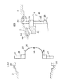
図1のベアリング固定用治具10は、所定幅のリング状部材11の外周面に、一条のねじ溝の如く螺旋状に延びる凹溝12を形成した構成である。
このベアリング固定用治具10は、テーパローラベアリング4装着部近傍のハブ2の内周面に形成された2つの突起13A,13Bにその凹溝12を嵌め合わせることにより、ハブ2内周面に装着される。
【0021】
この場合、前記突起13A,13Bは、ハブ2内周面の直径方向に離間する2部位に軸方向に前記凹溝12のねじピッチ分ずれて形成される。
かかるベアリング固定用治具10をハブ2内周面に装着するには、凹溝12にハブ2内周面の突起13A,13Bを合わせ、この状態で治具10を回動すると、凹溝12内を突起13A,13Bが移動し、これによって、治具10は軸方向に進行して、テーパローラベアリング4のインナーレース4Cに当接し、該インナーレース4Cを前記挿通方向と反対方向に移動不能に係止する。
【0022】
図2のベアリング固定用治具14は、所定幅のリング状部材15の外周面に、直径方向に離間する2部位から夫々周方向に沿って互いに異なる斜め方向に所定長さ(例えば、円周の1/4)延びる凹溝16を形成し、この凹溝16の一端部をその一端面にて開口し、他端部を閉止した構成である。
このベアリング固定用治具14は、テーパローラベアリング4装着部近傍のハブ2の内周面に形成された2つの突起17にその2つの凹溝16を嵌め合わせることにより、ハブ2内周面に装着される。
【0023】
この場合、前記突起17は、ハブ2内周面の直径方向に離間する2部位の軸方向の同一位置に形成される。
かかるベアリング固定用治具14をハブ2内周面に装着するには、凹溝16の開口位置にハブ2内周面の突起17を合わせ、この状態で治具14を回動すると、凹溝16内を突起17が移動し、これによって、治具10は軸方向に進行して、テーパローラベアリング4のインナーレース4Cに当接し、該インナーレース4Cを前記挿通方向と反対方向に移動不能に係止する。
【0024】
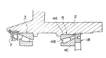
図3のベアリング固定用治具18は、所定幅のリング状部材19の外周面に、おねじ部20を形成した構成である。
このベアリング固定用治具18は、テーパローラベアリング4装着部近傍のハブ2の内周面に形成されためねじ部21にそのおねじ部20を嵌合することにより、ハブ2内周面に装着される。
【0025】
即ち、治具18をねじ込んでいくと、治具18は軸方向に進行して、テーパローラベアリング4のインナーレース4Cに当接し、該インナーレース4Cを前記挿通方向と反対方向に移動不能に係止する。
尚、図1〜図3に示した治具10,14,18においては、治具10,14,18の着脱時にこれを回動動作させるための工具の係合穴22,23,24が夫々端面の直径方向に離間する2部位に形成されている。
【0026】
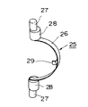
図4及び図5のベアリング固定用治具25は、略半円形状に湾曲され形成されたばね材からなる板部材26の両端部に夫々相反する方向に突出するピン27を固着取付し、かつこのピン27の基端部に偏心カム28を形成した構成である。この場合、前記偏心カム28は、板部材26の両端部を結ぶ線に対して90度の角度ずれた方向に長軸が延びるような略長円形断面を有する形状に形成される。
【0027】
尚、偏心カム28は、ピン27に一体成形しても良いし、ピン27とは別体に形成して、該ピン27に嵌合取付するようにしても良い。
又、前記板部材26の両端部間の中間部には、治具25の操作用のつまみ部29が設けられている。
このベアリング固定用治具25は、その両端部のピン27を、テーパローラベアリング4装着部近傍のハブ2の内周面に形成された2つの溝30に嵌め合わせることにより、ハブ内周面に装着される。
【0028】
この場合、前記溝30は、ハブ2内周面の直径方向に離間する2部位の軸方向の同一位置に形成される。
かかるベアリング固定用治具25をハブ2内周面に装着するには、板部材26をその両端部間の間隔が狭められるように押し縮め、両端部のピン27をハブ2内周面の溝30に嵌入させる。この状態では、偏心カム28の長軸はテーパローラベアリング4のインナーレース4C端面と平行する方向に延びている。そして、板部材26を90度回動させると、偏心カム28は、その長軸がテーパローラベアリング4のインナーレース4C端面と直交する方向に延びた位置となって、テーパローラベアリング4のインナーレース4Cに当接し、該インナーレース4Cを前記挿通方向と反対方向に移動不能に係止する。
【0029】
尚、図4(B)において、A,Bの寸法は、A<Bに設定する。
車両のアクスルを組み付けるに際して、以上の各図に示されたベアリング固定用治具を用いる場合、次のようにする。
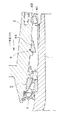
例えば、図3のベアリング固定用治具18を例にとって説明すると、アクスルケース1外周部にハブ2を挿通する前に、図6に示すように、ハブ2内周面にオイルシール7とハブ挿通方向の前側に位置するテーパローラベアリング3とを装着すると共に、ハブ挿通方向の後側に位置するテーパローラベアリング4のアウターレース4Aとテーパローラ4Bとインナーレース4Cとを装着し、このインナーレース4Cをベアリング固定用治具18により前記挿通方向と反対方向に移動不能に係止させ、図7に示すようにアクスルケース1外周部にハブ2を挿通し終わった後に前記治具18を取外すようにする。
【0030】
このように、アクスルケース1外周部にハブ2を挿通する前に、ハブ2内周面にオイルシール7とハブ挿通方向の前側に位置するテーパローラベアリング3とを装着すると共に、ハブ挿通方向の後側に位置するテーパローラベアリング4のインナーレース4Cをベアリング固定用治具により係止させておく結果、アクスルケース1外周部にハブ2を挿通する際の、該ハブ2とアクスルケース1両者のセンタリングが正確になり、両者のセンターにズレが生じ難くなり、挿通作業時に、オイルシール7やテーパローラベアリング3等のダメージを発生する虞がなくなる。
【0031】
即ち、組立作業が容易となると共に、品質の向上を図ることが可能となる。
【0032】
【発明の効果】
以上説明したように、請求項1,6及び11に係る発明によれば、アクスルケース外周部にハブを挿通する際の、該ハブとアクスルケース両者のセンタリングが正確になり、両者のセンターにズレが生じ難くなり、挿通作業時に、オイルシールやベアリング等のダメージを発生する虞がなくなり、組立作業が容易となると共に、品質の向上を図ることが可能となる。
【0033】
請求項2,3,7及び8に係る発明によると、リング状部材の回動により、ハブ挿通方向の後側に位置するベアリングのインナーレースの係止を容易に行え、しかも、ハブ側は凹溝を設けるだけの構成であるから、ハブの製作性に優れている。
請求項4及び9に係る発明によると、リング状部材の回動により、ハブ挿通方向の後側に位置するベアリングのインナーレースの係止を容易に行える。
【0034】
請求項5及び10に係る発明によると、板部材の回動により、ハブ挿通方向の後側に位置するベアリングのインナーレースの係止を容易に行え、しかも、ハブ側は溝を設けるだけの構成であるから、ハブの製作性に優れている。
【図面の簡単な説明】
【図1】本発明の一実施形態を示す図で、(A)は側面断面図、(B)はベアリング固定用治具の装着状態を示す部分断面図
【図2】本発明の他の実施形態を示す図で、(A)は側面断面図、(B)はベアリング固定用治具の装着状態を示す部分断面図
【図3】本発明の更に他の実施形態を示す図で、(A)は側面断面図、(B)はベアリング固定用治具の装着状態を示す部分断面図
【図4】本発明の更に他の実施形態を示す図で、(A)は側面断面図、(B)はベアリング固定用治具の装着状態を示す部分断面図
【図5】同上の実施形態におけるベアリング固定用治具の斜視図
【図6】図3の実施形態におけるベアリング固定用治具を用いたハブ組立方法を示す側面断面図
【図7】図3の実施形態におけるベアリング固定用治具を用いたハブ組立方法を示す側面断面図
【図8】図3の実施形態におけるベアリング固定用治具を用いたハブ組立方法を示す側面断面図
【図9】従来のアクスル構造を示す側面断面図
【図10】従来のハブ組立方法を示す側面断面図
【符号の説明】
1 アクスルケース
2 ハブ
3,4 テーパローラベアリング
4C インナーレース
5 アクスルシャフト
6 ボルト
10 ベアリング固定用治具
11 リング状部材
12 凹溝
13A,13B 突起
14 ベアリング固定用治具
16 凹溝
17 突起
18 ベアリング固定用治具
19 リング状部材
20 おねじ部
21 めねじ部
25 ベアリング固定用治具
26 板部材
27 ピン
28 偏心カム[0001]
TECHNICAL FIELD OF THE INVENTION
The present invention relates to a hub structure of an axle of a vehicle such as an automobile, a jig for fixing a bearing in a hub, and an axle assembling method using the jig for fixing a bearing, and relates to a technique for improving assembling workability and quality.
[0002]
[Prior art]
As a rear axle of a vehicle such as an automobile, as shown in FIG. 9, a
[0003]
This all-floating rear axle has the advantage that the
[0004]
[Problems to be solved by the invention]
By the way, when assembling the rear axle as described above, the
[0005]
In this case, as shown in FIG. 10, before the
[0006]
This is because when the
For this reason, after the
[0007]
However, in such an assembling method, when the
[0008]
The present invention has been made in view of the above, and when the axle of a vehicle such as an automobile is assembled, before the hub is inserted into the outer peripheral portion of the axle case, the seal member is located on the inner peripheral surface of the hub in front of the hub insertion direction. Not only the bearings, but also all the components of the bearing located on the rear side in the hub insertion direction, that is, the outer race, the rollers, and the inner race can all be mounted, thereby improving the axle assembly work and quality. The task is to improve the quality.
[0009]
[Means for Solving the Problems]
Therefore, the invention according to claim 1 is
In an axle of a vehicle, a hub is attached to an end of an axle case via two bearings, and an axle shaft inserted into the axle case is assembled to the hub by a fastener.
When the axle case is inserted through the inner peripheral surface of the hub to the outer peripheral portion of the hub, the inner race of the bearing located on the rear side in the insertion direction is immovably locked in a direction opposite to the insertion direction so as to be immovable. A jig mounting portion was formed.
[0010]
The invention according to
The jig has a configuration in which a concave groove extending spirally like a single thread groove is formed on an outer peripheral surface of a ring-shaped member having a predetermined width, and a mounting portion of the jig is arranged in a diametrical direction of a hub inner peripheral surface. The protrusions are formed at two positions separated from each other in the axial direction by a distance equal to the screw pitch of the groove, and are fitted into the groove.
[0011]
The invention according to
The jig is formed on an outer peripheral surface of a ring-shaped member having a predetermined width with a concave groove extending a predetermined length in a diagonal direction different from each other along two circumferential directions from two portions separated in a diametric direction, and one end of the concave groove. The jig mounting portion is formed at the same position in the axial direction at two diametrically spaced positions on the inner peripheral surface of the hub. The protrusion was fitted into the groove.
[0012]
The invention according to
The jig has a configuration in which a male thread portion is formed on an outer peripheral surface of a ring-shaped member having a predetermined width, and a mounting portion of the jig has an internal thread fitted on the inner peripheral surface of the hub with the male thread portion. Department.
The invention according to
The jig was fixedly attached to both ends of a plate member made of a spring material curved and formed into a substantially semicircular shape, and pins protruding in opposite directions, and an eccentric cam was formed at the base end of the pin. The mounting portion of the jig is formed at two axially separated positions on the inner peripheral surface of the hub at the same axial position, and is a groove into which the pin is fitted.
[0013]
The invention according to claim 6 is
In an axle of a vehicle, a hub is attached to an end of an axle case via two bearings, and an axle shaft inserted into the axle case is assembled to the hub by a fastener.
When the hub is inserted into the outer peripheral portion of the axle case, the inner race of the bearing located on the rear side in the insertion direction is detachably attached to the mounting portion on the inner peripheral surface of the hub, and the inner race of the bearing is positioned in the opposite direction to the insertion direction. To be immovable.
[0014]
The invention according to claim 7 is
The outer peripheral surface of the ring-shaped member having a predetermined width has a configuration in which a helically extending concave groove is formed like a single thread groove, and the concave groove is formed in two positions diametrically separated on the inner peripheral surface of the hub in the axial direction. The groove is fitted to a projection formed by being shifted by the screw pitch of the groove.
[0015]
The invention according to claim 8 is
On the outer peripheral surface of the ring-shaped member having a predetermined width, a concave groove extending a predetermined length in a diagonal direction different from each other along the circumferential direction is formed from two portions separated in a diametric direction, and one end of the concave groove is formed on one end surface thereof. And the other end is closed, and the concave groove is fitted to two axially spaced protrusions formed at the same position in the axial direction on the inner peripheral surface of the hub. .
[0016]
The invention according to claim 9 is
A male screw portion is formed on the outer peripheral surface of a ring-shaped member having a predetermined width, and the male screw portion is formed on the inner peripheral surface of the hub, so that the male screw portion is fitted to the screw portion.
The invention according to
Pins protruding in opposite directions are fixedly attached to both ends of a plate member made of a spring material curved and formed into a substantially semicircular shape, and an eccentric cam is formed at a base end of the pin. The pins are fitted into grooves formed at the same axial position at two diametrically separated positions on the inner peripheral surface of the hub.
[0017]
The invention according to claim 11 is
A hub is attached to an end portion of the axle case via two bearings, and an axle shaft inserted into the axle case is used when assembling an axle of a vehicle attached to the hub with a fastener.
Before inserting the hub into the outer peripheral portion of the axle case, the seal member and the bearing located on the front side in the hub insertion direction are mounted on the inner peripheral surface of the hub, and the outer race and roller of the bearing located on the rear side in the hub insertion direction. And the inner race of the bearing is immovably locked in the direction opposite to the insertion direction by a jig that is detachably attached to the inner peripheral surface of the hub, and after the hub is inserted through the outer peripheral portion of the axle case. An axle assembling method using a jig for fixing a bearing in a hub from which the jig is removed.
[0018]
BEST MODE FOR CARRYING OUT THE INVENTION
Hereinafter, embodiments of the present invention will be described in detail with reference to the drawings.
In FIG. 8, a rear axle of a vehicle such as an automobile has a
[0019]
Here, the
There are four bearing fixing jigs shown in FIGS. 1, 2, 3, 4 and 5.
[0020]
This will be described in order.
The
The
[0021]
In this case, the
To mount the
[0022]
The
The
[0023]
In this case, the
In order to mount the
[0024]
The
Since this
[0025]
That is, as the
In addition, in the
[0026]
The
[0027]
The
A
The
[0028]
In this case, the
In order to mount the
[0029]
In FIG. 4B, the dimensions of A and B are set so that A <B.
When assembling the vehicle axle, when using the bearing fixing jig shown in each of the above figures, the following is performed.
For example, taking the
[0030]
As described above, before the
[0031]
That is, the assembling work becomes easy, and the quality can be improved.
[0032]
【The invention's effect】
As described above, according to the first, sixth, and eleventh aspects of the invention, when the hub is inserted into the outer peripheral portion of the axle case, the centering of the hub and the axle case becomes accurate, and the center of the hub and the axle case are displaced. Is less likely to occur, and there is no danger of causing damage to the oil seal and the bearing during the insertion operation, so that the assembling operation is facilitated and the quality can be improved.
[0033]
According to the second, third, seventh and eighth aspects of the present invention, the inner race of the bearing located on the rear side in the hub insertion direction can be easily locked by the rotation of the ring-shaped member. Since only the grooves are provided, the hub is excellent in manufacturability.
According to the fourth and ninth aspects of the invention, the inner race of the bearing located on the rear side in the hub insertion direction can be easily locked by the rotation of the ring-shaped member.
[0034]
According to the fifth and tenth aspects of the present invention, the rotation of the plate member allows the inner race of the bearing located on the rear side in the hub insertion direction to be easily locked, and the hub side is simply provided with a groove. Therefore, the manufacturability of the hub is excellent.
[Brief description of the drawings]
FIG. 1 is a view showing an embodiment of the present invention, in which (A) is a side sectional view, and (B) is a partial sectional view showing a mounted state of a bearing fixing jig. FIG. 3A is a side sectional view, FIG. 3B is a partial sectional view showing a mounted state of a bearing fixing jig. FIG. 3 is a view showing still another embodiment of the present invention. ) Is a side sectional view, (B) is a partial sectional view showing a mounted state of a bearing fixing jig. FIG. 4 is a view showing still another embodiment of the present invention, (A) is a side sectional view, (B) ) Is a partial cross-sectional view showing a mounted state of the bearing fixing jig. [FIG. 5] A perspective view of the bearing fixing jig in the embodiment described above. [FIG. 6] A bearing fixing jig in the embodiment of FIG. FIG. 7 is a side sectional view showing a hub assembling method. FIG. 8 is a side sectional view showing a hub assembling method using the bearing fixing jig in the embodiment of FIG. 3; FIG. 9 is a side sectional view showing a conventional axle structure; Side sectional view showing a conventional hub assembling method.
Reference Signs List 1
Claims (11)
前記ハブの内周面に、前記アクスルケースをハブ外周部に挿通する際に、挿通方向の後側に位置するベアリングのインナーレースを前記挿通方向と反対方向に移動不能に係止する着脱自由な治具の取付部を形成したことを特徴とする車両のアクスルのハブ構造。In an axle of a vehicle, a hub is attached to an end of an axle case via two bearings, and an axle shaft inserted into the axle case is assembled to the hub by a fastener.
When the axle case is inserted through the inner peripheral surface of the hub to the outer peripheral portion of the hub, the inner race of the bearing located on the rear side in the insertion direction is immovably locked in a direction opposite to the insertion direction so as to be immovable. An axle hub structure for a vehicle, wherein a jig mounting portion is formed.
前記ハブの内周面の取付部に着脱自由に取り付けられて、前記アクスルケース外周部に前記ハブを挿通する際に、挿通方向の後側に位置するベアリングのインナーレースを前記挿通方向と反対方向に移動不能に係止する構成を特徴とする車両のアクスルのハブにおけるベアリング固定用治具。In an axle of a vehicle, a hub is attached to an end of an axle case via two bearings, and an axle shaft inserted into the axle case is assembled to the hub by a fastener.
When the hub is inserted into the outer peripheral portion of the axle case, the inner race of the bearing located on the rear side in the insertion direction is detachably attached to the mounting portion on the inner peripheral surface of the hub, and the inner race of the bearing is positioned in the opposite direction to the insertion direction. A jig for fixing a bearing on a hub of an axle of a vehicle, characterized in that the jig is immovably locked on the hub.
アクスルケース外周部にハブを挿通する前に、ハブ内周面にシール部材とハブ挿通方向の前側に位置するベアリングとを装着すると共に、ハブ挿通方向の後側に位置するベアリングのアウターレースとローラとを装着し、かつ該ベアリングのインナーレースをハブ内周面に着脱自由に取り付けられた治具により前記挿通方向と反対方向に移動不能に係止させ、アクスルケース外周部にハブを挿通した後に前記治具を取外すようにしたことを特徴とするハブにおけるベアリング固定用治具を用いたアクスル組立方法。A hub is attached to an end portion of the axle case via two bearings, and an axle shaft inserted into the axle case is used when assembling an axle of a vehicle attached to the hub with a fastener.
Before inserting the hub into the outer peripheral portion of the axle case, the seal member and the bearing located on the front side in the hub insertion direction are mounted on the inner peripheral surface of the hub, and the outer race and roller of the bearing located on the rear side in the hub insertion direction. And the inner race of the bearing is immovably locked in the direction opposite to the insertion direction by a jig that is detachably attached to the inner peripheral surface of the hub, and after the hub is inserted through the outer peripheral portion of the axle case. An axle assembling method using a jig for fixing a bearing in a hub, wherein the jig is removed.
Priority Applications (1)
| Application Number | Priority Date | Filing Date | Title |
|---|---|---|---|
| JP08528696A JP3556762B2 (en) | 1996-04-08 | 1996-04-08 | Hub structure for vehicle axle, jig for fixing bearing in hub, and axle assembling method using jig for fixing bearing |
Applications Claiming Priority (1)
| Application Number | Priority Date | Filing Date | Title |
|---|---|---|---|
| JP08528696A JP3556762B2 (en) | 1996-04-08 | 1996-04-08 | Hub structure for vehicle axle, jig for fixing bearing in hub, and axle assembling method using jig for fixing bearing |
Publications (2)
| Publication Number | Publication Date |
|---|---|
| JPH09272305A JPH09272305A (en) | 1997-10-21 |
| JP3556762B2 true JP3556762B2 (en) | 2004-08-25 |
Family
ID=13854335
Family Applications (1)
| Application Number | Title | Priority Date | Filing Date |
|---|---|---|---|
| JP08528696A Expired - Fee Related JP3556762B2 (en) | 1996-04-08 | 1996-04-08 | Hub structure for vehicle axle, jig for fixing bearing in hub, and axle assembling method using jig for fixing bearing |
Country Status (1)
| Country | Link |
|---|---|
| JP (1) | JP3556762B2 (en) |
Families Citing this family (2)
| Publication number | Priority date | Publication date | Assignee | Title |
|---|---|---|---|---|
| CN110549790B (en) * | 2018-05-30 | 2024-04-02 | 镇江裕久智能装备股份有限公司 | Lightweight aluminum alloy hub |
| JP7047745B2 (en) | 2018-12-17 | 2022-04-05 | 株式会社豊田自動織機 | Hub structure |
-
1996
- 1996-04-08 JP JP08528696A patent/JP3556762B2/en not_active Expired - Fee Related
Also Published As
| Publication number | Publication date |
|---|---|
| JPH09272305A (en) | 1997-10-21 |
Similar Documents
| Publication | Publication Date | Title |
|---|---|---|
| EP0799389B1 (en) | Bearing assembly utilizing improved clamping arrangement | |
| JP3634897B2 (en) | Bolt fitting structure | |
| US6018869A (en) | Method of manufacturing a wheel hub assembly | |
| US4988231A (en) | Bushing | |
| JP2007520668A (en) | Wheel bearing outer race and outer race stopper | |
| JP3556762B2 (en) | Hub structure for vehicle axle, jig for fixing bearing in hub, and axle assembling method using jig for fixing bearing | |
| JP2002219903A (en) | Bearing unit for driving wheel | |
| JPH10324108A (en) | Bearing locknut and washer structure | |
| US6905249B2 (en) | Bearing locking mechanism | |
| US4373831A (en) | Key device for locking an element to a shaft | |
| JP3678864B2 (en) | Motor bearing structure | |
| US6595085B1 (en) | Differential bearing cap | |
| JPH071257Y2 (en) | Bearing mounting jig | |
| JP4126774B2 (en) | Engine assembly method and apparatus | |
| JP2683324B2 (en) | Door handle mounting seat | |
| JP2681876B2 (en) | Manufacturing method of universal joint | |
| JP2884494B2 (en) | Door hinge structure for vehicles | |
| US6945728B2 (en) | Mechanical fastener | |
| JPH11108038A (en) | Mounting structure for thrust washer | |
| KR0167434B1 (en) | Locking ring assembly of a steering column shaft | |
| JP3323672B2 (en) | Universal joint and manufacturing method thereof | |
| JP2002039202A (en) | Rolling rotational bearing | |
| KR200153370Y1 (en) | Brake drum assembly | |
| JPH0125746Y2 (en) | ||
| JPS6011323Y2 (en) | Rotary transmission element assembly structure inside the transmission case |
Legal Events
| Date | Code | Title | Description |
|---|---|---|---|
| A977 | Report on retrieval |
Free format text: JAPANESE INTERMEDIATE CODE: A971007 Effective date: 20040325 |
|
| TRDD | Decision of grant or rejection written | ||
| A01 | Written decision to grant a patent or to grant a registration (utility model) |
Free format text: JAPANESE INTERMEDIATE CODE: A01 Effective date: 20040511 |
|
| A61 | First payment of annual fees (during grant procedure) |
Free format text: JAPANESE INTERMEDIATE CODE: A61 Effective date: 20040513 |
|
| R150 | Certificate of patent or registration of utility model |
Free format text: JAPANESE INTERMEDIATE CODE: R150 |
|
| LAPS | Cancellation because of no payment of annual fees |